ASTM E505 图谱
- 格式:pdf
- 大小:130.39 KB
- 文档页数:2
Designation:E155−10Standard Reference Radiographs forInspection of Aluminum and Magnesium Castings1This standard is issued under thefixed designation E155;the number immediately following the designation indicates the year of original adoption or,in the case of revision,the year of last revision.A number in parentheses indicates the year of last reapproval.A superscript epsilon(´)indicates an editorial change since the last revision or reapproval.These Reference Radiographs have been developed in cooperation with the Quality Control Committee and Aerospace Research and Testing Committee of the Aerospace Industries Association.This standard has been approved for use by agencies of the Department of Defense.1.Scope1.1These reference radiographs illustrate the types and degrees of discontinuities that may be found in aluminum-alloy and magnesium-alloy castings.The castings illustrated are in thicknesses of1⁄4in.(6.35mm)and3⁄4in.(19.1mm).The reference radiographfilms are an adjunct to this document and must be purchased separately from ASTM International if needed.1.2Thesefilm reference radiographs are not intended to illustrate the types and degrees of discontinuities found in aluminum-alloy castings when performing digital radiography. If performing digital radiography of aluminum-alloy castings, refer to Digital Reference Image Standard E2422.Magnesium-alloy digital reference images are not currently available from ASTM International.1.3This document may be used where no other applicable document exists,for other material thicknesses for which it has been found to be applicable and for which agreement has been reached between the purchaser and the manufacturer.1.4The values stated in inch-pound units are to be regarded as the standard.The values given in parentheses are mathemati-cal conversions to SI units that are provided for information only and are not considered standard.1.5This standard does not purport to address all of the safety concerns,if any,associated with its use.It is the responsibility of the user of this standard to establish appro-priate safety and health practices and determine the applica-bility of regulatory limitations prior to use.N OTE1—V ol I:The set of reference radiographs consists of13plates covering discontinuities in aluminum-alloy castings and10plates cover-ing discontinuities in magnesium-alloy castings.Each plate is held in an 81⁄2by11-in.(216by279-mm)cardboard frame and each plate illustrates eight grades of severity for the discontinuity in approximately a2by2-in.(51by51-mm)area.The cardboard frames are contained in a101⁄2by 111⁄2-in.(267by292-mm)ring binder.The reference radiographs are not impacted by this revision.There have been no revisions to the adjunct reference radiographs since original issue.The adjunct reference radio-graphs of any issue remain valid and may be used to this standard.V ol.II:The set of reference radiographs consists of four plates covering discontinuities in magnesium-alloy castings only.Each plate is held in an 81⁄2by11-in.(216by279-mm)cardboard frame and illustrates eight grades of severity for the discontinuity(with the exception of discrete discontinuities,where only one example of each discontinuity is given).N OTE2—Reference radiographs applicable to aluminum and magne-sium die castings up to1in.(25mm)in thickness are contained in Reference Radiographs E505.2.Referenced Documents2.1ASTM Standards:2E94Guide for Radiographic ExaminationE505Reference Radiographs for Inspection of Aluminum and Magnesium Die CastingsE1316Terminology for Nondestructive ExaminationsE2422Digital Reference Images for Inspection of Alumi-num Castings2.2ASTM Adjuncts:Reference Radiographs for Inspection of Aluminum and Magnesium Castings:V olume I,Aluminum and Magnesium Castings3V olume II,Magnesium Castings43.Terminology3.1Definitions—Definitions of terms used in this standard may be found in Terminology E1316.3.2Definitions of Terms Specific to This Standard:3.2.1The terms relating to discontinuities used in these reference radiographs are described based upon radiographic appearance.1These reference radiographs are under the jurisdiction of ASTM Committee E07on Nondestructive Testing and are the direct responsibility of Subcommittee E07.02on Reference Radiological Images.Current edition approved Sept.1,2010.Published September2010.Originally approved st previous edition approved in2005as E155-05.DOI: 10.1520/E0155-10.2For referenced ASTM standards,visit the ASTM website,,or contact ASTM Customer Service at service@.For Annual Book of ASTM Standards volume information,refer to the standard’s Document Summary page on the ASTM website.3Available from ASTM International Headquarters.Order Reference Radio-graph No.ADJE015501.4Available from ASTM International Headquarters.Order Reference Radio-graph No.ADJE015502.Copyright©ASTM International,100Barr Harbor Drive,PO Box C700,West Conshohocken,PA19428-2959.United States3.2.2foreign materials—appear as isolated,irregular,or elongated variations offilm density,not corresponding to variations in thickness of material,nor to cavities.They may be due to the presence of sand,slag,oxide or dross,or metal of different density.3.2.3gas holes—appear as round or elongated,smooth-edged dark spots,occurring individually,in clusters,or distrib-uted throughout the casting.3.2.4gas porosity—represented by round or elongated dark spots corresponding to minute voids usually distributed through the entire casting.3.2.5microshrinkage(feathery type)—microshrinkage hav-ing an elongated appearance resembling feather-like streaks.3.2.6microshrinkage(sponge type)—microshrinkage hav-ing a spongelike appearance,and more massive and equiaxed than the feathery type.3.2.7reacted sand inclusions—appear on radiograph as “spotty segregation,”that is,sharply defined round light areas, about1mm in diameter,and often with the rim lighter than the center.They are entrapped sand particles that underwent reaction with molten magnesium alloys containing zirconium (Note3).3.2.8segregations—appear as variations infilm density which can be explained by segregation of elements of atomic numbers different from that of the matrix.3.2.8.1gravity segregation—appears white on radiograph and may range from a mottling-type effect through white-diffused spots blending with the matrix,to a cloud-like appearance in more severe cases.They are agglomerations of particles precipitated at temperatures above liquidus(Note3).3.2.8.2eutectic segregation—type of segregation is gener-ally represented when a defect or discontinuity develops during solidification and is fed with a near eutectic residual liquid rich with alloying elements that have a high X-ray attenuation.One exception to this enrichment as illustrated in Reference Radio-graphs E155isflow line(or eutectic depletion),where there is a local impoverishment of the alloying elements that have a high X-ray attenuation(Note3).(1)eutectic segregation—microshrinkage type—type of seg-regation develops when a microshrinkage develops during solidification,and is fed with residual liquid rich in dense alloying elements such as thorium.The area will show light ona radiograph(Note3).(2)eutectic segregation—pipe-shrink type—type of segre-gation develops during solidification when a pipe shrink forms and is immediatelyfilled with eutectic liquid rich in high X-ray attenuation alloying elements.The area shows light on a radiograph as a feathery or dendritic feature(Note3).(3)eutectic segregation—hot-tear type—type of segregation develops during solidification when the hot tear that takes place is immediatelyfilled with liquid rich in alloying elements high in X-ray attenuation.The defect shows as white or light irregular defined lines(Note3).(4)eutectic depletion—flow line—type of segregation devel-ops when a section of a mold isfilled by liquid and solidifies at the front before liquid from another feed meets the solid front.A portion of the solid front then partially melts; otherwise,the discontinuity would be a cold shut.Solidifica-tion begins after this remelt and the initial crystals are of high purity and contain fewer high-density alloying elements than the melt average.Since the metal is stillflowing across these crystals,the composition ahead of this solidifying front is depleted.This depletion of the eutectic shows on the radio-graph as a dark diffused line(Note3).(5)oxide inclusions in magnesium alloys containing zirconium—show on a radiograph as well defined light area of irregular shape and size resembling a radiograph of a com-pactedfine steel wool.It is composed of complex magnesium oxidefilm with high zirconium content,and,if present,rare earths and thorium oxides also.It is often associated with zirconium-rich particles.N OTE3—More detailed descriptions of these discontinuities can be found in the article,“New Reference Radiographs for Magnesium Alloy Castings,”by gowski,published in the Journal of Testing and Evaluation,V ol2,No.4,July1974.3.2.9shrinkage cavity—appears as a dendritic,filamentary, or jagged darkened area.3.2.10shrinkage porosity or sponge(nonferrous alloys)—a localized lacy or honeycombed darkened area.4.Significance and Use4.1These radiographs are intended for reference only but are so designed that acceptance standards,which may be developed for particular requirements,can be specified in terms of these radiographs.The illustrations are radiographs of castings that were produced under conditions designed to develop the discontinuities.The radiographs of the1⁄4-in.(6.35-mm)castings are intended to be used in the thickness range up to and including1⁄2in.(12.7mm).The radiographs of the3⁄4-in.(19.1-mm)castings are intended to be used in the thickness range of over1⁄2in.to and including2in.(51mm). The grouping and system of designations are based on consid-erations of the best practical means of making these reference radiographs of the greatest possible value.4.2Film Deterioration—Radiographicfilms are subject to wear and tear from handling and use.The extent to which the image deteriorates over time is a function of storage conditions,care in handling and amount of use.Reference radiographfilms are no exception and may exhibit a loss in image quality over time.The radiographs should therefore be periodically examined for signs of wear and tear,including scratches,abrasions,stains,and so forth.Any reference radio-graphs which show signs of excessive wear and tear which could influence the interpretation and use of the radiographs should be replaced.5.Basis for Application5.1The reference radiographs may be applied as acceptance standards tailored to the end use of the product.Application of these reference radiographs as acceptance standards should be based on the intended use of the product and the following considerations(see Note4).5.1.1Compare the production radiographs of the casting submitted for evaluation with the reference radiographs appli-cable to designated wall thickness in accordance with the written acceptance criteria.5.1.2An area of like size to that of the reference radiograph shall be the unit area by which the production radiograph is evaluated,and any such area shall meet the requirements as defined for acceptability.5.1.3Any combination or portion of these reference radio-graphs may be used as is relevant to the particular application. Different grades or acceptance limits may be specified for each discontinuity type.Furthermore,different grades may be speci-fied for different regions or zones of a component.5.1.4Special considerations may be required where more than one discontinuity type is present in the same area.Any modifications to the acceptance criteria required on the basis of multiple discontinuity types must be specified.5.1.5Where the reference radiographs provide only an ungraded illustration of a discontinuity,acceptance criteria may be specified by referencing a maximum discontinuity size, or percentage of the discontinuity size illustrated.5.1.6Production radiographs showing porosity,gas, shrinkage,or inclusions shall be evaluated by the overall condition with regard to size,number,and distribution.The aggregate size of discontinuities shall not exceed the total accumulation in area of the discontinuities of the reference radiograph.It is not the intent that the maximum size of the illustrated discontinuity shall be the limiting size for a single production radiographic discontinuity,or that the number of discontinuities shown on the reference radiograph shall be the limiting number for production radiographs.Also,caution should be exercised in judging a large discontinuity against a collection of small discontinuities on the basis of size alone. Each of the factors of size,number,and distribution must be considered in balance.The purchaser may provide documented specific methods of evaluation.5.1.7When the severity level of discontinuities per unit in the production radiograph being evaluated is equal to or better than the severity level in the specified reference radiograph, that part of the casting represented by the production radio-graph shall be acceptable.If the production radiograph showsdiscontinuities per unit area of greater severity than the reference radiograph,that part of the casting shall not be accepted.5.1.8As a minimum the acceptance criteria should contain information addressing:zoning of the part(if applicable),the acceptable severity level for each discontinuity type,and the specified area to which the reference radiographs are to be applied.N OTE4—Caution should be exercised in specifying the acceptance criteria to be met in a casting.Casting design coupled with foundry practice should be considered.It is advisable to consult with the manufacturer/foundry before establishing the acceptance criteria to ensure the desired quality level can be achieved.6.Description6.1The radiographs listed in Table1illustrate each type of discontinuity in eight grades.The radiographs listed in Table2 illustrate each type of discontinuity in eight grades,with the exception of pipe shrink,flow line,hot tear and oxide inclusion,where a single ungraded illustration is given for each.Although eight grades of each discontinuity are shown (with the above exceptions),a numerically smaller graded set of discontinuities based on these reference radiographs could be used for acceptance standards.Each grade is illustrated in approximately a2by2-in.(51by51-mm)area.The radio-graphic technique used is in agreement with Guide E94,and produced a desired density of2.0to2.25.6.2The alloys used to reproduce the various discontinuities were as listed in Table3.N OTE5—Misruns,core shift,cold shut,and surface irregularities are not illustrated,as they are readily identifiable by surface inspection or by other means of nondestructive testing.6.3All of these references are original radiographs;they should be viewed by transmitted light.TABLE1Reference Radiographs for Aluminum and MagnesiumCastings—Volume IDiscontinuityCastingThickness,in.AApplicableCastingThickness,in.AAluminum-Alloy CastingsGas holes1⁄4up to1⁄2,inclGas holes3⁄4over1⁄2to2,incl Gas porosity(round)1⁄4up to1⁄2,inclGas porosity(round)3⁄4over1⁄2to2,incl Gas porosity(elongated)1⁄4up to1⁄2,inclGas porosity(elongated)3⁄4over1⁄2to2,incl Shrinkage cavity1⁄4All thicknesses Shrinkage(sponge)1⁄4up to1⁄2,incl Shrinkage(sponge)3⁄4over1⁄2to2,incl Foreign material(less dense)1⁄4up to1⁄2,incl Foreign material(less dense)3⁄4over1⁄2to2,incl Foreign material(more dense)1⁄4up to1⁄2,incl Foreign material(more dense)3⁄4over1⁄2to2,inclMagnesium-Alloy CastingsGas holes1⁄4up to1⁄2,inclGas holes3⁄4over1⁄2to2,incl Microshrinkage(feathery)1⁄4up to1⁄2,incl Microshrinkage(feathery)3⁄4over1⁄2to2,incl Microshrinkage(sponge)1⁄4up to1⁄2,incl Microshrinkage(sponge)3⁄4over1⁄2to2,incl Foreign material(less dense)1⁄4up to1⁄2,incl Foreign material(less dense)3⁄4over1⁄2to2,incl Foreign material(more dense)1⁄4up to1⁄2,incl Foreign material(more dense)3⁄4over1⁄2to2,inclA1in.=25.4mm.TABLE2Reference Radiographs for Magnesium Castings—Volume IIDiscontinuityCastingThickness,in.AApplicableCastingThickness,in.A Eutectic segregation(discrete discontinui-ties)—pipeshrink,flow line,hot tears,oxideinclusions1⁄4all thicknesses Reacted sand inclusion1⁄4all thicknesses Eutectic segregation(microshrinkage type)1⁄4all thicknesses Gravity segregation1⁄4all thicknesses A1in.=25.4mm.7.Keywords7.1aluminum;castings;discontinuities;magnesium;refer-ence radiographs;X-rayASTM International takes no position respecting the validity of any patent rights asserted in connection with any item mentioned in this ers of this standard are expressly advised that determination of the validity of any such patent rights,and the risk of infringement of such rights,are entirely their own responsibility.This standard is subject to revision at any time by the responsible technical committee and must be reviewed every five years and if not revised,either reapproved or withdrawn.Your comments are invited either for revision of this standard or for additional standards and should be addressed to ASTM International Headquarters.Your comments will receive careful consideration at a meeting of the responsible technical committee,which you may attend.If you feel that your comments have not received a fair hearing you should make your views known to the ASTM Committee on Standards,at the address shown below.This standard is copyrighted by ASTM International,100Barr Harbor Drive,PO Box C700,West Conshohocken,PA 19428-2959,United States.Individual reprints (single or multiple copies)of this standard may be obtained by contacting ASTM at the above address or at 610-832-9585(phone),610-832-9555(fax),or service@ (e-mail);or through the ASTM website ().Permission rights to photocopy the standard may also be secured from the ASTM website (/COPYRIGHT/).TABLE 3Actual Alloys Used to Reproduce DiscontinuitiesDiscontinuityAlloy UsedAluminumGas holes356Gas porosity (round)356Gas porosity (elongated)195Shrinkage cavity 356Shrinkage (sponge)356Foreign material (less dense)356Foreign material (more dense)356MagnesiumGas holesZK51A Eutectic segregation and flow line EZ33A Gravity segregationZK91Microshrinkage (feathery)AZ91C Microshrinkage (sponge)AZ91C Foreign material (less dense)AZ91C Foreign material (more dense)AZ91C Reacted sand inclusionsHK31A Oxide inclusion in magnesium alloys containing zirconiumHZ11。
压铸件质量标准
1. 范围
1.1本《气孔和铸件质量要求》标准适用于压铸件。
1.2所有的线性尺寸单位为英寸
2. 定义
砂眼一一铸件中由夹带气体引起的表面缺陷。
冷隔 -- 由于金属的凝固速率不同,有时在压铸过程中产生的凝固金属的重叠。
内部缩孔一一铸件冷凝期间的一种情况,铸件内部体积收缩而形成空隙但铸件的外形尺寸没有减小。
穿透性缺陷一一铸件中有一个闭环孔或通孔,其孔径大于0.005(0.127伽)但不属于设计部分。
注:本标准中所指的“穿透性缺陷”均参照以上的定义3.分类
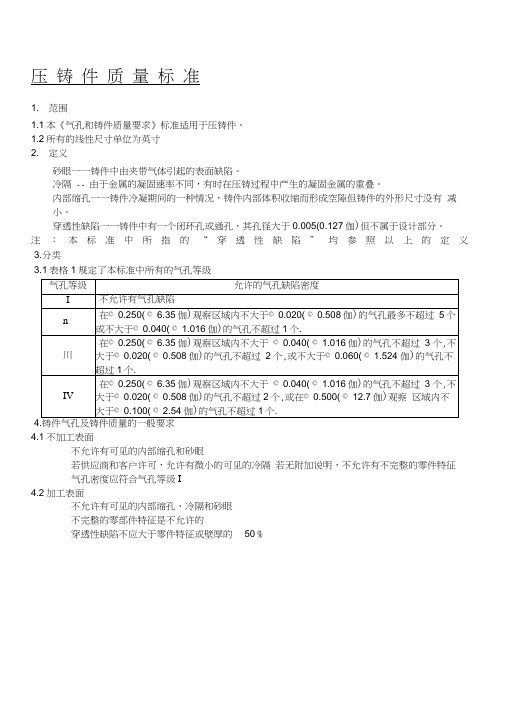
3.1表格1规定了本标准中所有的气孔等级
4.1不加工表面
不允许有可见的内部缩孔和砂眼
若供应商和客户许可,允许有微小的可见的冷隔若无附加说明,不允许有不完整的零件特征
气孔密度应符合气孔等级I
4.2加工表面
不允许有可见的内部缩孔、冷隔和砂眼
不完整的零部件特征是不允许的
穿透性缺陷不应大于零件特征或壁厚的50 %。
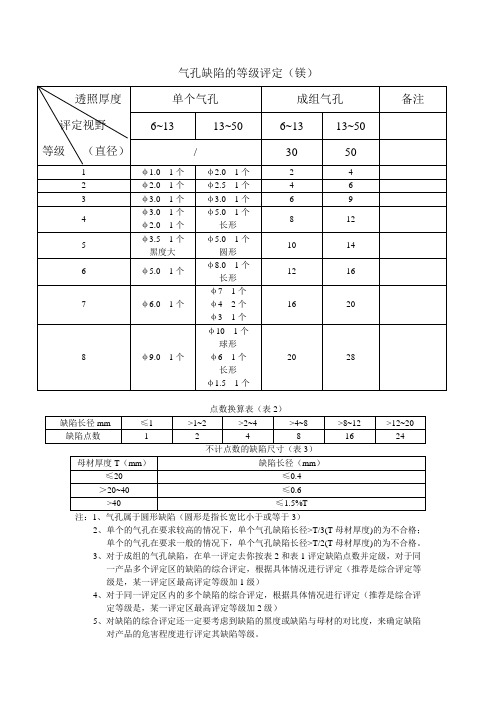
注:1、气孔属于圆形缺陷(圆形是指长宽比小于或等于3)2、单个的气孔在要求较高的情况下,单个气孔缺陷长径>T/3(T母材厚度)的为不合格;单个的气孔在要求一般的情况下,单个气孔缺陷长径>T/2(T母材厚度)的为不合格。
3、对于成组的气孔缺陷,在单一评定去你按表2和表1评定缺陷点数并定级,对于同一产品多个评定区的缺陷的综合评定,根据具体情况进行评定(推荐是综合评定等级是,某一评定区最高评定等级加1级)4、对于同一评定区内的多个缺陷的综合评定,根据具体情况进行评定(推荐是综合评定等级是,某一评定区最高评定等级加2级)5、对缺陷的综合评定还一定要考虑到缺陷的黑度或缺陷与母材的对比度,来确定缺陷对产品的危害程度进行评定其缺陷等级。
注:1、条孔或条渣属于条形缺陷(圆形是指长宽比大于3)2、单个的条孔或条渣在要求较高的情况下,单个条孔或条渣缺陷长径>T/3(T母材厚度)的为不合格;单个的条孔或条渣在要求一般的情况下,单个条孔或条渣缺陷长径>T/2(T母材厚度)的为不合格。
3、对于成组的条孔或条渣缺陷,对与同一产品多个评定区的缺陷的综合评定,根据具体情况进行评定(推荐是综合评定等级是,某一评定区最高评定等级加1级)。
4、对于同一评定区内的多个缺陷的综合评定,根据具体情况进行评定(推荐是综合评定等级是,某一评定区最高评定等级加2级)。
5、对缺陷的综合评定还一定要考虑到缺陷的黑度或缺陷与母材的对比度,来确定缺陷对产品的危害程度进行评定其缺陷等级。
度)的为不合格;单个的低密度夹渣在要求一般的情况下,单个低密度夹渣缺陷长径>T/2(T母材厚度)的为不合格。
2、对于成组的低密度夹渣缺陷,对与同一产品多个评定区的缺陷的综合评定,根据具体情况进行评定(推荐是综合评定等级是,某一评定区最高评定等级加1级)。
3、对于成组的低密度夹渣缺陷,在单一评定去你按表2和表1评定缺陷点数并定级,对于同一产品多个评定区的缺陷的综合评定,根据具体情况进行评定(推荐是综合评定等级是,某一评定区最高评定等级加1级)4、对于同一评定区内的多个缺陷的综合评定,根据具体情况进行评定(推荐是综合评定等级是,某一评定区最高评定等级加2级)。


ASTME505中文版
压铸件质量标准
1. 范围
1.1 本《气孔和铸件质量要求》标准适用于压铸件。
1.2 所有的线性尺寸单位为英寸
2. 定义
砂眼——铸件中由夹带气体引起的表面缺陷。
冷隔——由于金属的凝固速率不同,有时在压铸过程中产生的凝固金属的重叠。
内部缩孔——铸件冷凝期间的一种情况,铸件内部体积收缩而形成空隙但铸件的外形尺寸没有减小。
穿透性缺陷——铸件中有一个闭环孔或通孔,其孔径大于0.005(0.127㎜)但不属于设计部分。
注:本标准中所指的“穿透性缺陷”均参照以上的定义。
3. 分类
3.1 表格1规定了本标准中所有的气孔等级
4. 铸件气孔及铸件质量的一般要求
4.1 不加工表面
不允许有可见的内部缩孔和砂眼
若供应商和客户许可,允许有微小的可见的冷隔? 若无附加说明,不允许有不完整的零件特征
气孔密度应符合气孔等级Ⅰ
4.2 加工表面
不允许有可见的内部缩孔、冷隔和砂眼
不完整的零部件特征是不允许的
穿透性缺陷不应大于零件特征或壁厚的50℅。
气孔标准
1. 压铸参考:(参考ASTM E505)
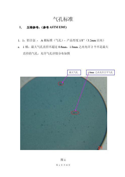
1.1:铝合金 - A 极标准(气孔)- 产品厚度1/8’’(3.2mm 以内) a. 1极:最大气孔直径不超过0.6mm ,1.0mm 之内允许2个不是最大
直径的气孔,允许气孔详情分布如图
图
1
直径的气孔,2.0之内允许3个不是最大气孔,允许气孔详情分布如图2:
图2
直径的气孔,气孔可以较密集,但气孔须较小,允许气孔分布详情如图3
d.4极,最大气孔外径为2.5×5,不允许这样的大气孔连续出现。
气孔
密集,最大气孔周围允许小气孔。
如图4
1.2:铝合金 - A 极标准(气孔)- 产品厚度5/8’’(15.9mm 以内) a. 1极:最大气孔直径不超过1.0mm ,3.5mm 之内允许2个不是最大直径的气孔,气孔不能连续分布,详情分布如图5
图5
径的气孔,气孔不能连续分布,详情分布如图6
图6
的气孔,气孔不能连续分布,详情分布如图7
图7
径的气孔,气孔不能连续分布,详情分布如图8
图8。

astm-e505标准三级管控ASTM E505标准是由美国材料和试验协会(ASTM International)制定的一项测试方法标准,主要用于测量和描述非金属薄片制品的表面平整度。
该标准包含了三个不同级别的管控,通过分别检测和分类表面平整度的不同级别,可以确定和控制产品的质量。
ASTM E505标准的三级管控是指根据标准将被测试样品的表面平整度分为三个级别,从而对产品质量进行评估和管控。
三个级别分别是A 级、B级和C级,每个级别都有相应的指标和要求。
在ASTM E505标准中,A级是指最高标准的表面质量,要求非常严格,用于要求非常高的应用,如光学和电子设备。
B级是指中等标准的表面质量,要求适中,用于大多数一般应用。
C级是指相对较低的表面质量,适用于对表面质量要求不高的一般应用。
根据ASTM E505标准的要求,进行表面平整度测试需要使用光学测量设备,如激光扫描仪或显微镜。
测试过程包括扫描或观察被测样品表面,并测量表面的凸起或凹陷程度。
根据测量结果,可以将样品分为不同的级别。
通过进行ASTM E505标准的三级管控,可以确保产品的表面质量符合特定的要求,并能够满足用户的需求。
对于高精度应用,选择A级的产品可以保证表面质量的最佳性能。
对于一般应用,选择B级的产品可以满足大多数需求。
对于表面质量要求不高的应用,选择C级的产品能够节省成本并满足基本要求。
ASTM E505标准的三级管控对于制造商和用户来说都非常重要。
对制造商来说,可以根据不同的应用需求进行产品的分级和分类,以便提供符合用户需求的产品。
对用户来说,可以根据产品的级别选择最适合自己需求的产品,确保获得满意的产品质量。
总之,ASTM E505标准的三级管控是一种用于评估和管控非金属薄片制品表面平整度的方法。
通过将产品分为A级、B级和C级,可以根据不同应用需求选择最适合的产品,以确保产品表面质量的符合要求。
这种标准对于制造商和用户来说都非常重要,能够提高产品质量并满足用户需求。
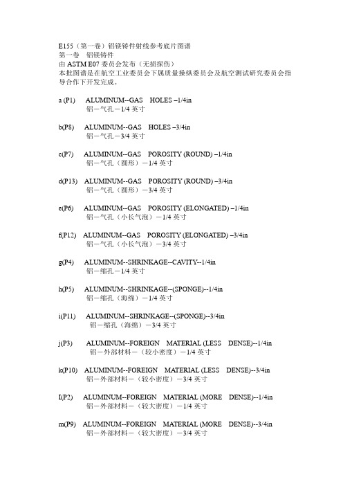
E155(第一卷)铝镁铸件射线参考底片图谱第一卷铝镁铸件由ASTM E07委员会发布(无损探伤)本批图谱是在航空工业委员会下属质量操纵委员会及航空测试研究委员会指导合作下开发完成。
a (P1) ALUMINUM--GAS HOLES –1/4in铝-气孔-1/4英寸b(P8) ALUMINUM--GAS HOLES –3/4in铝-气孔-3/4英寸c(P7) ALUMINUM--GAS POROSITY (ROUND) –1/4in铝-气孔(圆形)-1/4英寸d(P13) ALUMINUM--GAS POROSITY (ROUND) –3/4in铝-气孔(圆形)-3/4英寸e(P6) ALUMINUM--GAS POROSITY (ELONGATED) –1/4in铝-气孔(小长气泡)-1/4英寸f(P12) ALUMINUM--GAS POROSITY (ELONGATED) –3/4in铝-气孔(小长气泡)-3/4英寸g(P4) ALUMINUM--SHRINKAGE--CA VITY--1/4in铝-缩孔-1/4英寸h(P5) ALUMINUM--SHRINKAGE--(SPONGE)--1/4in铝-缩孔(海绵)-1/4英寸i(P11) ALUMINUM--SHRINKAGE--(SPONGE)--3/4in铝-缩孔(海绵)-3/4英寸j(P3) ALUMINUM--FOREIGN MATERIAL (LESS DENSE)--1/4in 铝-外部材料-(较小密度)-1/4英寸k(P10) ALUMINUM--FOREIGN MATERIAL (LESS DENSE)--3/4in 铝-外部材料-(较小密度)-3/4英寸I(P2) ALUMINUM--FOREIGN MATERIAL (MORE DENSE)--1/4in 铝-外部材料-(较大密度)-1/4英寸m(P9) ALUMINUM--FOREIGN MATERIAL (MORE DENSE)--3/4in 铝-外部材料-(较大密度)-3/4英寸n(P14) MAGNESIUM—GAS HOLES—1/4in镁-气孔-1/4英寸o(P19) MAGNESIUM—GAS HOLES—3/4in镁-气孔-3/4英寸p(P17) MAGNESIUM—MICROSHRINKAGE (FEATHERY)—1/4in 镁-微缩孔(羽毛状)-1/4英寸q(P22) MAGNESIUM—MICROSHRINKAGE (FEATHERY)—3/4in 镁-微缩孔(羽毛状)-3/4英寸r(P18) MAGNESIUM—MICROSHRINKAGE (SPONGE)—1/4in镁-缩孔(海绵状)-1/4英寸s(P23) MAGNESIUM—MICROSHRINKAGE (SPONGE)—3/4in镁-缩孔(海绵状)-3/4英寸t(P16) MAGNESIUM—FOREIGN MATERIAL (LESS DENSE)—1/4in 镁-外部材料(较小密度)-1/4英寸u(P21) MAGNESIUM—FOREIGN MATERIAL (LESS DENSE)—3/4in 镁-外部材料(较小密度)-3/4英寸v(P15) MAGNESIUM—FOREIGN MATERIAL (MORE DENSE)—1/4in 镁-外部材料(较大密度)-1/4英寸w(P20) MAGNESIUM—FOREIGN MATERIAL (MORE DENSE)—3/4in 镁-外部材料(较大密度)-3/4英寸E155(第二卷)铝镁铸件射线参考底片图谱第二卷镁铸件由ASTM E07委员会发布(无损探伤)本批图谱是在航空工业委员会下属质量操纵委员会及航空测试研究委员会指导合作下开发完成。

压铸件质量标准
1.范围
1.1 本《气孔和铸件质量要求》标准适用于压铸件。
1.2 所有的线性尺寸单位为英寸
2.定义
砂眼——铸件中由夹带气体引起的表面缺陷。
冷隔——由于金属的凝固速率不同,有时在压铸过程中产生的凝固金属的重叠。
内部缩孔——铸件冷凝期间的一种情况,铸件内部体积收缩而形成空隙但铸件的外形尺寸没有减小。
穿透性缺陷——铸件中有一个闭环孔或通孔,其孔径大于0.005(0.127㎜)但不属于设计部分。
注:本标准中所指的“穿透性缺陷”均参照以上的定义。
3.分类
4.铸件气孔及铸件质量的一般要求
4.1不加工表面
➢不允许有可见的内部缩孔和砂眼
➢若供应商和客户许可,允许有微小的可见的冷隔
➢若无附加说明,不允许有不完整的零件特征
➢气孔密度应符合气孔等级Ⅰ
4.2加工表面
➢不允许有可见的内部缩孔、冷隔和砂眼
➢不完整的零部件特征是不允许的
➢穿透性缺陷不应大于零件特征或壁厚的50℅。
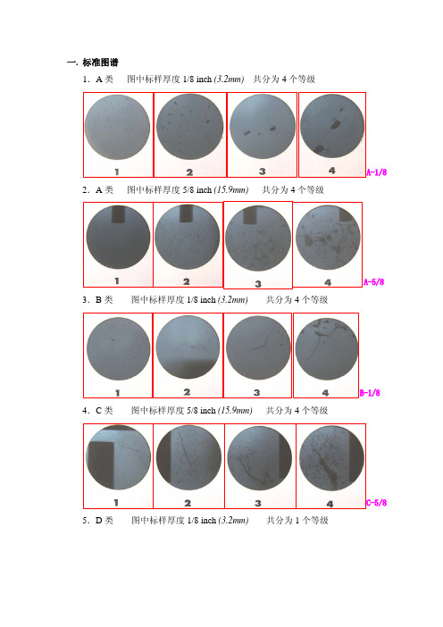
一. 标准图谱
1.A类图中标样厚度1/8 inch (3.2mm)共分为4个等级
2.A类图中标样厚度5/8 inch (15.9mm)共分为4个等级
3.B类图中标样厚度1/8 inch (3.2mm)共分为4个等级
4.C类图中标样厚度5/8 inch (15.9mm)共分为4个等级
5.D类图中标样厚度1/8 inch (3.2mm)共分为1个等级
压铸企业可联系我,我们需要构造起周边的压铸环境,相互学习,相互提升,甚至我们应该集体考虑产品价格问题,不要任凭国外的企业打压产品价格,其实他们购买的中国产品+运费还远远低于他们国内的购买价格。
如果他们大肆压价,又要求我们PPM<=50,我们将彻底成为国外的机器,干得又好又便宜。
低利润长时间运行,会导致没有足够的资金进行技术革新,提高我们的生产技术,永远处于劣势……
对于外国企业我们有付出,就要有更高的回报,从而我们需要壮大自己,改变自己,真正能过以后我们为我们的国家贡献点什么…….我们是把祖国的资源卖给他们,需要我们深思!
先不多说,搞铝合金和镁合金压铸的,有空联系我
fultureliu@。

astm-e505标准三级管控ASTM-E505标准是针对金属和陶瓷材料的表面粗糙度的测量方法,属于表面分析和测量技术领域。
该标准将表面粗糙度划分为三个级别:一级、二级和三级。
这三个级别分别对应不同的应用要求和测量精度。
在进行表面粗糙度检测时,根据需求可选择不同的级别进行测试和评估。
一级管控是最高级别,对于要求非常高的应用场景,如光学镜面、信号处理器等,一级管控要求材料表面非常光滑,没有明显的缺陷。
一级管控的测量结果一般以RMS(均方根)值或Ra(平均粗糙度)值进行表示,其测量结果要求非常精确,对测量设备的要求也相当高。
二级管控是中级别,适用于一些一般要求的应用场景。
材料表面在二级管控下,可以有一些细微的缺陷和粗糙度。
测量结果一般以RMS 值或Ra值进行表示,对于表面缺陷的度量也有相应的要求。
二级管控的精度相对较低,对测量设备的要求也相对较低。
三级管控是最低级别,适用于一些粗糙度要求不高的应用场景。
材料表面在三级管控下,可以有较大的缺陷和粗糙度。
测量结果一般以RMS值或Ra值进行表示,对于表面缺陷的度量也有相应的要求。
三级管控的精度相对较低,对测量设备的要求也相对较低。
ASTM-E505标准通过对不同级别的管控,为金属和陶瓷材料的表面粗糙度提供了统一的测量准则,方便了工程设计和制造过程的控制。
厂商可以根据应用需求选择适当的级别进行测试和管控,从而保证产品的质量和性能。
在进行表面粗糙度测试时,需要使用专用的测量仪器,如表面粗糙度仪、激光扫描仪等。
测试前,需要对仪器进行校准,确保其测量结果的准确性和可靠性。
测试过程中,将测量仪器轻轻地放置在材料表面,仪器将通过测量探针或激光扫描来获取表面的粗糙度信息,最后通过计算得到RMS值或Ra值。
ASTM-E505标准的应用范围广泛,涉及到许多行业,如航空航天、汽车制造、电子工业等。
这些行业对于金属和陶瓷材料表面的粗糙度要求严格,需要通过精确的测量和管控来确保产品质量。

ASTME505中⽂版
压铸件质量标准
1.范围
1.1 本《⽓孔和铸件质量要求》标准适⽤于压铸件。
1.2 所有的线性尺⼨单位为英⼨
2.定义
砂眼——铸件中由夹带⽓体引起的表⾯缺陷。
冷隔——由于⾦属的凝固速率不同,有时在压铸过程中产⽣的凝固⾦属的重叠。
内部缩孔——铸件冷凝期间的⼀种情况,铸件内部体积收缩⽽形成空隙但铸件的外形尺⼨没有减⼩。
穿透性缺陷——铸件中有⼀个闭环孔或通孔,其孔径⼤于0.005(0.127㎜)但不属于设计部分。
注:本标准中所指的“穿透性缺陷”均参照以上的定义。
3.分类
4.铸件⽓孔及铸件质量的⼀般要求
不加⼯表⾯
不允许有可见的内部缩孔和砂眼
若供应商和客户许可,允许有微⼩的可见的冷隔
若⽆附加说明,不允许有不完整的零件特征
⽓孔密度应符合⽓孔等级Ⅰ
加⼯表⾯
不允许有可见的内部缩孔、冷隔和砂眼
不完整的零部件特征是不允许的
穿透性缺陷不应⼤于零件特征或壁厚的50℅。

astm e505 标准好的,以下是一篇完整的《astm e505 标准》的文档,不含敏感信息:一、标准概述ASTM E505标准是建筑材料燃烧性能评估的重要标准,旨在保障火灾发生时人们的生命安全和财产安全。
该标准提供了建筑材料在火灾中的燃烧特性和安全性的评估方法,根据建筑材料的燃烧性能将其分为不同的等级。
二、建筑材料分类根据ASTM E505标准,建筑材料被分为A级、B级、C级等不同等级,反映了材料在火灾中的燃烧特性和蔓延速度。
这些等级是根据建筑材料在模拟火灾条件下的燃烧性能测试结果而确定的。
三、测试方法ASTM E505标准规定了测试建筑材料燃烧性能的方法和程序,包括样品准备、测试设备、测试过程和结果评估等。
测试过程通常包括点燃建筑材料、观察其燃烧情况、测量燃烧蔓延速度、评估烟雾产生和毒性等指标。
测试结果将用于确定建筑材料的燃烧性能等级,并为建筑设计和使用提供参考。
四、安全要求根据ASTM E505标准,为了确保建筑物的安全,建筑设计应考虑逃生和灭火措施。
建筑物的构造应能够阻止火势蔓延,并为人员提供足够的时间和空间进行逃生。
此外,建筑物内的消防设施也应得到充分的维护和检查。
五、实施与监督ASTM E505标准规定了各方的责任和义务,包括测试机构、生产厂家、销售商和使用者等。
测试机构应按照标准要求进行测试,并出具报告。
生产厂家应确保其产品符合标准要求,并承担相应的质量责任。
销售商和使用者也应了解标准要求,并在购买和使用过程中注意安全。
六、参考文献本标准引用了以下文献:1. ASTM E162 建筑材料分类和标记标准2. ASTM E84 建筑制品及材料燃烧性能试验方法标准3. 其他相关标准和规范以上参考文献提供了本标准的背景和依据,确保标准的科学性和准确性。
七、附录附录A:建筑材料燃烧性能等级表附录B:测试设备和材料清单附录C:测试过程和结果记录表附录A提供了常见建筑材料的燃烧性能等级,方便使用者查阅。


Designation:E505–01Standard Reference Radiographs forInspection of Aluminum and Magnesium Die Castings1This standard is issued under thefixed designation E505;the number immediately following the designation indicates the year of original adoption or,in the case of revision,the year of last revision.A number in parentheses indicates the year of last reapproval.A superscript epsilon(e)indicates an editorial change since the last revision or reapproval.1.Scope1.1These reference radiographs illustrate the categories and severity levels of discontinuities that may occur in aluminum-alloy and magnesium-alloy die castings.They are intended to provide:1.1.1A guide enabling recognition of discontinuities and their differentiation both as to type and severity level through radiographic examination.1.1.2Example radiographic illustrations of discontinuities and a nomenclature for reference in acceptance standards, specifications,and drawings.1.1.3The values stated in inch-pounds are to be regarded as standard.N OTE1—The set of reference radiographs consists offive81⁄2by11-in. cardboard frames containing radiographs covering discontinuities in aluminum and magnesium alloy die castings.Thefirst four frames each contain two sets of four graded levels of increasing severity,while the last frame contains two ungraded radiographs.The5frames are contained in a101⁄2by111⁄2-in.ring binder.N OTE2—Reference radiographs applicable to aluminum and magne-sium castings up to2in.(50mm)in thickness are contained in ASTM Reference Radiographs E155,for Inspection of Aluminum and Magne-sium Castings,V olumes I and II.1.2Two kinds of illustration categories are covered as follows:1.2.1Graded—Three discontinuity categories for alumi-num die castings and three discontinuity categories for mag-nesium die castings,each illustrated in four levels of progres-sively increasing severity.Category A discontinuities are illustrated for aluminum and magnesium die castings having thicknesses of1⁄8in.(3.2mm)and5⁄8in.(15.9mm);Category B discontinuities are illustrated for1⁄8-in.thick aluminum and magnesium die castings;and Category C discontinuities are illustrated for5⁄8-in.thick aluminum and magnesium die castings.1.2.2Ungraded—One illustration of one discontinuity for 0.20-in.(5.1-mm)thickness aluminum die casting;and one illustration of one discontinuity for1⁄8-in.(3.2-mm)thickness magnesium die casting.1.3This document may be used for other materials,thick-nesses,or with other energy levels for which it has been found to be applicable and agreement has been reached between the purchaser and manufacturer.1.4This standard does not purport to address all of the safety concerns,if any,associated with its use.It is the responsibility of the user of this standard to establish appro-priate safety and health practices and determine the applica-bility of regulatory limitations prior to use.2.Referenced Documents2.1ASTM Standards:E94Guide for Radiographic Examination2E155Reference Radiographs for Inspection of Aluminum and Magnesium Castings2E1316Terminology for Nondestructive Examinations2 2.2ASTM Adjuncts:Reference Radiographs for Inspection of Aluminum and Magnesium Die Castings33.Terminology3.1Definitions—For definitions of terms used in this docu-ment,see Terminology E1316.4.Appearance of Radiographic Indications4.1The following descriptions are for use in discontinuity identification and classification.These descriptions apply to these reference radiographs only.4.1.1Category A(Porosity)—Round or elongated,smooth-edged dark spots occurring individually distributed or in clusters.4.1.2Category B(Cold Fill)—A distinct darkened line or band of variable length and definite smooth outline,usually continuous or interconnected.4.1.3Category C(Shrinkage)—Filamentary or jagged dark-ened areas,usually continuous or interconnected.4.1.4Category D(Foreign Material)—Isolated irregular variation infilm density,either lighter or darker than surround-ing areas.They may indicate the inclusion of oxide or dross or metallic compounds of different density.Illustration shows a more dense material.1These reference radiographs are under the jurisdiction of ASTM Committee E07on Nondestructive Testing and is the direct responsibility of Subcommittee E07.02on Reference Radiological Images.Current edition approved June10,2001.Published August2001.Originally published as E505–st previous edition E505–96.2Annual Book of ASTM Standards,V ol03.03.3Available from ASTM Headquarters.Order RRE0505. 1Copyright©ASTM International,100Barr Harbor Drive,PO Box C700,West Conshohocken,PA19428-2959,United States.5.Significance and Use5.1These radiographs are so designed that acceptance standards,which may be developed for particular require-ments,can be specified in terms of these radiographs.The radiographs are of castings that were produced under condi-tions designed to produce the discontinuities.These reference radiographs are intended to be used for casting thickness ranges in accordance with Table1.5.2The radiographic illustrations listed in Table1illustrate three types of discontinuities in four severity levels.Two ungraded illustrations have been included to establish the radiographic appearance of foreign material.5.3These reference radiographs were produced in accor-dance with Guide E94.All of the references are original radiographs.5.4Film Deterioration—Radiographicfilms are subject to wear and tear from handling and use.The extent to which the image deteriorates over time is a function of storage condi-tions,care in handling and amount of use.Reference radio-graphfilms are no exception and may exhibit a loss in image quality over time.The radiographs should therefore be peri-odically examined for signs of wear and tear,including scratches,abrasions,stains,and so forth.Any reference radio-graphs which show signs of excessive wear and tear which could influence the interpretation and use of the radiographs should be replaced.6.Basis for Application6.1These reference radiographs may be applied as accep-tance standards tailored to the end use of the product.Appli-cation of these reference radiographs as acceptance standards should be based on the intended use of the product and the following considerations(see Note3):6.1.1Unless otherwise specified,discontinuities of equal or lesser severity than that in the specified reference radiograph are acceptable in any specified unit area of the casting.The size of the unit area should be specified in the acceptance criteria. Discontinuities more severe than those in the specified refer-ence radiograph shall be considered rejectable.6.1.2Any combination or portion of these reference radio-graphs may be used as is relevant to the particular application. Different grades or acceptance limits may be specified for each discontinuity type.Further,different grades may be specified for various regions or zones of the component.6.1.3Special consideration may be required where more than one discontinuity type is present in the same area.Any modification of the acceptance criteria required on the basis of multiple discontinuity types must be specified.6.1.4Where the reference radiograph contains multiple discontinuities,as in that case of gas holes,acceptance may be based upon the aggregate area of the discontinuities,the maximum discontinuity size in the reference radiograph,the spacing between discontinuities,or a combination of these or other criteria,or both.6.1.5As a minimum the acceptance criteria should contain information addressing;zoning of the part(if applicable), acceptance severity level for each discontinuity type,and the specific area to which the reference radiographs are to be applied.N OTE3—Caution should be exercised in specifying the acceptance criteria to be met in the casting.Casting design coupled with foundry practice should be considered.It is advisable to consult with the manufacturer or foundry before establishing the acceptance criteria to ensure the desired quality level can be achieved.7.Keywords7.1aluminum;die castings;discontinuities;magnesium; reference radiographs;X-rayTABLE1Reference Radiographs for Aluminum and Magnesium Die CastingsDiscontinuityPlate Thickness,in.(mm)Applicable CastingThickness,in.(mm) Aluminum Die CastingsCategory A(Porosity)1⁄8(3.2)up to3⁄8(9.5),incl Category A(Porosity)5⁄8(15.9)over3⁄8to1(9.5to25.4),inclCategory B(Coldfill)1⁄8(3.2)up to3⁄8(9.5),incl Category C(Shrinkage)5⁄8(15.9)over3⁄8to1(9.5to25.4),inclCategory D(Foreignmaterial)0.200(5.08)up to1(25.4),inclMagnesium Die CastingsCategory A(Porosity)1⁄8(3.2)up to3⁄8(9.5),incl Category A(Porosity)5⁄8(15.9)over3⁄8to1(9.5to25.4),inclCategory B(Coldfill)1⁄8(3.2)up to3⁄8(9.5),incl Category C(Shrinkage)5⁄8(15.9)over3⁄8to1(9.5to25.4),inclCategory D(Foreign material)1⁄8(3.2)up to1(25.4),inclASTM International takes no position respecting the validity of any patent rights asserted in connection with any item mentioned in this ers of this standard are expressly advised that determination of the validity of any such patent rights,and the risk of infringement of such rights,are entirely their own responsibility.This standard is subject to revision at any time by the responsible technical committee and must be reviewed everyfive years and if not revised,either reapproved or withdrawn.Your comments are invited either for revision of this standard or for additional standards and should be addressed to ASTM International Headquarters.Your comments will receive careful consideration at a meeting of the responsible technical committee,which you may attend.If you feel that your comments have not received a fair hearing you should make your views known to the ASTM Committee on Standards,at the address shown below.This standard is copyrighted by ASTM International,100Barr Harbor Drive,PO Box C700,West Conshohocken,PA19428-2959, United States.Individual reprints(single or multiple copies)of this standard may be obtained by contacting ASTM at the above address or at610-832-9585(phone),610-832-9555(fax),or service@(e-mail);or through the ASTM website ().。
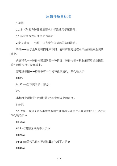
压铸件质量标准1.范围1.1本《气孔和铸件质量要求》标准适用于压铸件。
1.2所有的线性尺寸单位为英寸2.定义砂眼——铸件中由夹带气体引起的表面缺陷。
冷隔——由于金属的凝固速率不同,有时在压铸过程中产生的凝固金属的重叠。
内部缩孔——铸件冷凝期间的一种情况,铸件内部体积收缩而形成空隙但铸件的外形尺寸没有减小。
穿透性缺陷——铸件中有一个闭环孔或通孔,其孔径大于0.005(0.127㎜)但不属于设计部分。
注:本标准中所指的“穿透性缺陷”均参照以上的定义。
3.分类3.1表格1规定了本标准中所有的气孔等级允许的气孔缺陷密度Ⅰ不允许有气孔缺陷在φ0.250(φ6.35㎜)观察区域内不大于φ0.020(φ0.508㎜)的气孔最多不超过Ⅱ5个或不大于φ0.040(φ1.016㎜)的气孔不超过1个.在φ0.250(φ6.35㎜)观察区域内不大于φ0.040(φ1.016㎜)的气孔不超过3Ⅲ个,不大于φ0.020(φ0.508㎜)的气孔不超过2个,或不大于φ0.060(φ1.524㎜)的气孔不超过1个.在φ0.250(φ6.35㎜)观察区域内不大于φ0.040(φ1.016㎜)的气孔不超过3Ⅳ个,不大于φ0.020(φ0.508㎜)的气孔不超过2个,或在φ0.500(φ12.7㎜)观察区域内不大于φ0.100(φ2.54㎜)的气孔不超过1个.4.铸件气孔及铸件质量的一般要求不加工表面不允许有可见的内部缩孔和砂眼若供应商和客户许可,允许有微小的可见的冷隔若无附加说明,不允许有不完整的零件特征气孔密度应符合气孔等级Ⅰ加工表面不允许有可见的内部缩孔、冷隔和砂眼不完整的零部件特征是不允许的穿透性缺陷不应大于零件特征或壁厚的50℅。
一. 标准图谱
1.A类图中标样厚度1/8 inch (3.2mm)共分为4个等级
2.A类图中标样厚度5/8 inch (15.9mm)共分为4个等级
3.B类图中标样厚度1/8 inch (3.2mm)共分为4个等级
4.C类图中标样厚度5/8 inch (15.9mm)共分为4个等级
5.D类图中标样厚度1/8 inch (3.2mm)共分为1个等级
压铸企业可联系我,我们需要构造起周边的压铸环境,相互学习,相互提升,甚至我们应该集体考虑产品价格问题,不要任凭国外的企业打压产品价格,其实他们购买的中国产品+运费还远远低于他们国内的购买价格。
如果他们大肆压价,又要求我们PPM<=50,我们将彻底成为国外的机器,干得又好又便宜。
低利润长时间运行,会导致没有足够的资金进行技术革新,提高我们的生产技术,永远处于劣势……
对于外国企业我们有付出,就要有更高的回报,从而我们需要壮大自己,改变自己,真正能过以后我们为我们的国家贡献点什么…….我们是把祖国的资源卖给他们,需要我们深思!
先不多说,搞铝合金和镁合金压铸的,有空联系我
fultureliu@。