DP550操作手册
- 格式:pdf
- 大小:910.83 KB
- 文档页数:26

Waves API 550 User ManualTABLE OF CONTENTSCHAPTER 1 – INTRODUCTION (3)1.1W ELCOME (3)1.2P RODUCT O VERVIEW (4)1.3C OMPONENTS (5)CHAPTER 2 – QUICKSTART GUIDE (6)CHAPTER 3 – CONTROLS AND INTERFACE (7)3.1EQ S ECTION (8)3.2O UTPUT S ECTION (12)3.3W AVESYSTEM T OOLBAR (13)APPENDIX A – 550A CONTROLS (14)APPENDIX B – 550B CONTROLS (14)Waves API 550 User ManualChapter 1 – Introduction1.1 WelcomeThank you for choosing Waves! In order to get the most out of your new Waves plugin, please take a moment to read this user guide.To install software and manage your licenses, you need to have a free Waves account. Sign up at . With a Waves account you can keep track of your products, renew your Waves Update Plan, participate in bonus programs, and keep up to date with important information.We suggest that you become familiar with the Waves Support pages: /support. There are technical articles about installation, troubleshooting, specifications, and more. Plus, you’ll find company contact information and Waves Support news.Waves API 550 User Manual1.2 Product OverviewThe Waves API 550 consists of the API 550A, a 3-Band parametric equalizer with 5 fixed cutoff points per band and the API 550B, a 4-Band parametric equalizer with 7 fixed cutoff points per band. Modeled on the late 1960’s legend, the API 550A EQ delivers a sound that has been a hallmark of high end studios for decades. It provides reciprocal equalization at 15 points in 5 steps of boost divided into three overlapping ranges. The high and low frequency ranges are individually selectable as either peaking or shelving, and a band-pass filter can be inserted independently of all other settings. Featuring four overlapped EQ bands, the API 550B features 7 switchable filter frequencies spanning up to 5 octaves per band. “Proportional Q” automatically widens the filter bandwidth at lower settings and narrows it at higher settings. It even lets you undo previous processing, affect or even reverse tonal modifications. With its vast range of tonal possibilities, the API 550B is an exceptionally versatile EQ.Waves API 550 User Manual1.3 ComponentsWaveShell technology enables us to split Waves processors into smaller plug-ins, which we call components. Having a choice of components for a particular processor gives you the flexibility to choose the configuration best suited to your material.The API 550 has four component processors:API 550A Stereo – A 3-Band stereo equalizerAPI 550A Mono – A 3-Band mono equalizerAPI 550B Stereo – A 4-Band stereo equalizerAPI 550B Mono – A 4-Band mono equalizerWaves API 550 User ManualChapter 2 – Quickstart GuideApproach the Waves API 550 as you would any conventional EQ. Since the API 550 features “Proportional Q,” which intuitively widens the filter bandwidth at lower settings and narrows it at higher settings, feel free to push the API 550 harder than you normally would other equalizers. The API 550 will deliver smooth, natural, and musical sound even at the most extreme settings.Waves API 550 User ManualChapter 3 – Controls and InterfaceWaves API 550 User Manual3.1 EQ SectionAPI 550A ControlsLow Band GainRange-12dB to +12dB (2-3dB steps)Default0dBLow Band FrequencyFilter typesShelf, BellDefaultShelfCutoff points50Hz, 100Hz, 200Hz, 300Hz, 400HzDefault50HzMid Band GainRange-12dB to +12dB (2-3dB steps)Default0dBWaves API 550 User ManualMid Band FrequencyRange.4kHz, .8kHz, 1.5kHz, 3kHz, 5kHzDefault1.5kHzFilter typesBellHigh Band GainRange-12dB to +12dB (2-3dB steps)Default0dBHigh Band FrequencyRange5kHz, 7kHz, 10kHz, 12.5kHz, 15kHzDefault7kHzBandpass FilterApplies a 50Hz-15kHz bandpass filter to the entire signalLow Shelf/Bell SelectorRangeShelf or BellDefaultShelfHigh Shelf/Bell SelectorRangeShelf or BellDefaultShelfWaves API 550 User ManualAPI 550B ControlsLow Band GainRange-12dB to +12dB (2-3dB steps)Default0dBLow Band FrequencyRange30Hz, 40Hz, 50Hz, 100Hz, 200Hz, 300Hz, 400HzDefault50HzFilter typesShelf, BellCutoff points30Hz, 40Hz, 50Hz, 100Hz, 200Hz, 300Hz, 400HzLow Mid Band GainRange-12dB to +12dB (2-3dB steps)Default0dBLow Mid Band FrequencyRange75Hz, 150Hz, 180Hz, 240Hz, 500Hz, 700Hz, 1kHzDefault500HzFilter typesBellCutoff points75Hz, 150Hz, 180Hz, 240Hz, 500Hz, 700Hz, 1kHzHigh Mid Band GainRange-12dB to +12dB (2-3dB steps)Default0dBWaves API 550 User ManualHigh Mid Band FrequencyRange0.8kHz, 1.5kHz, 3kHz, 5kHz, 8kHz, 10kHz, 12.5kHzDefault5kHzFilter typesBellCutoff points0.8kHz, 1.5kHz, 3kHz, 5kHz, 8kHz, 10kHz, 12.5kHzHigh Band GainRange-12dB to 12dB (2-3dB steps)DefaultOffHigh Band FrequencyRange2.5kHz, 5kHz, 7kHz, 10kHz, 12.5kHz, 15kHz, 20kHzDefault10kHzFilter typesShelf, BellCutoff points2.5kHz, 5kHz, 7kHz, 10kHz, 12.5kHz, 15kHz, 20kHzLow Shelf/Bell SelectorRangeShelf or BellDefaultShelfHigh Shelf/Bell SelectorRangeShelf or BellDefaultShelfInTurns the EQ On/Off but leaves the Analog modeling.RangeOn/OffDefaultOnWaves API 550 User Manual3.2 Output SectionThe Output section, which is identical on both the API 550A and API 550B, consists of controls for Polarity (Phase Inversion) Analog Modeling, Output Level, and Trim.Pol (Polarity)Shifts the phase by 180 degrees.Range0deg-180degDefault0degAnalogTurns the Analog modeling on and off.RangeOn/OffDefaultO ffWaves API 550 User ManualOutput Controls the output level. Range -18dB to +18dB (in 0.1dB steps)Default 0dB Trim Displays the maximum peak level of the output signal and its distance from nominal gain (-0.1dBfs). Range -inf to 0dB Default -infMetersThe API 550 meters display output level in dBFS. The LED located between the two meters lights up when output signal is clipping.Waves API 550 User Manual3.3 WaveSystem ToolbarUse the bar at the top of the plugin to save and load presets, compare settings, undo and redo steps, and resize the plugin. To learn more, click the icon at the upper-right corner of the window and open the WaveSystem Guide.Appendix A – 550A Controls Control Range Default Low Band Gain -12dB to 12dB (2-3dB’s steps)0dB Low Band Frequency 50Hz,100Hz,200Hz,300Hz,400Hz 50Hz Mid Band Gain -12dB to 12dB(2-3dB’s steps)0dB Mid Band Frequency .4kHz,.8kHz,1.5kHz,3kHz,5kHz. 1.5kHz High Band Gain -12dB to 12dB(2-3dB’s steps)0dB High Band Frequency 5kHz,7kHz,10kHz,12.5kHz,15kHz.7kHz Filter Bandpass 50Hz-15kHz Off Low shelf/bell selector Shelf or Bell Shelf High shelf/bell selector Shelf or Bell Shelf Output -18dB to 18dB 0dB Trim -inf to 0dB -inf AnalogOn/Off O ff Phase 0deg- 180deg 0deg Appendix B – 550B ControlsWaves API 550 User ManualControl Range Default Low Band Gain -12dB to 12dB(2-3dB’s steps)0dB Low Band Frequency 30Hz,40Hz,50Hz,100Hz,200Hz,300Hz,400Hz 50Hz Low Mid Band Gain -12dB to 12dB(2-3dB’s steps)0dB Low Mid Band Frequency 75Hz,150Hz,180Hz,240Hz,500Hz,700Hz,1kHz. 500Hz High Mid Band Gain -12dB to 12dB(2-3dB’s steps)0dB High Mid Band Frequency 0.8kHz,1.5kHz,3kHz,5kHz,8kHz,10kHz,12.5kHz. 5kHz High Band Gain -12dB to 12dB(2-3dB’s steps)Off High Band Frequency 2.5kHz,5kHz,7kHz,10kHz,12.5kHz,15kHz,20kHz. 10kHz Low shelf/bell selector Shelf or Bell Shelf High shelf/bell selector Shelf or Bell Shelf Output -18dB to 18dB 0dB Trim -inf to 0dB -inf AnalogOn/Off O ff Phase 0deg- 180deg0deg。

Aruba 550 系列校园接入点启动指南安装本设备必须由经过培训的 Aruba 认证移动专业人员 (ACMP) 或有类似资格的 Aruba 认证技术人员安装和维修。
安装本设备之前,请参阅 Aruba 550 系列接入点安装指南,为此请扫描本节给出的二维码,或者访问 ,然后选择Documentation (文档)> Hardware Installation Guides (硬件安装指南)> Access Points (接入点)> 555 Series Campus Access Points (550系列校园接入点)。
软件有关初始设置和软件配置的说明,请参阅最新版本的 AP Software Quick Start Guide (接入点软件快速开始指南),为此请扫描本节给出的二维码,或者访问 ,打开 Documentation (文档)选项卡,然后选择 Software User & Reference Guides (软件用户及参考指南) > Aruba Unified 。
软件最终用户许可协议如需本产品的最终用户许可协议 (EULA) 信息,请访问 /assets/legal/EULA.pdf 。
0512028-CN-02Aruba 550 系列校园接入点(AP-555)是具有多重射频的高性能无线设备,可以部署到基于控制器 (ArubaOS) 或无控制器 (InstantOS) 的网络环境。
这些接入点通过 4x4 MIMO (多重输入多重输出)无线电并发提供高性能 2.4 GHz 和 5 GHz 802.11ax Wi-Fi (Wi-Fi 6) 功能,同时还支持传统802.11a/b/g 无线服务。
背面的有线以太网端口用于将本设备连接到有线网络基础设施(两个端口均支持最高 5 Gbps 的有线网速),并为本设备提供 POE 电源(802.3at4 级或 802.3bt5 级)。

Group 系列产品培训© Polycom, Inc. All rights reserved.© Polycom 公司版权所有。
保留所有权利。
2目录Group系列硬件安装与初始化Group系列产品介绍Group系列本地管理配置Group系列诊断与维护2134© Polycom 公司版权所有。
保留所有权利。
3HDCI 摄像头输入EagleEye Acoustic 音频输入内容输入HDMI + VGA 音频输入3.5mmCLink2 音频输入主音频输出 #13.5mm 视频输出 #1HDMI 视频输出 #2HDMI USB 串口网口1Gbps电源输入RealPresence 500 背板图© Polycom 公司版权所有。
保留所有权利。
4RealPresence Group 550 背板图接地电源HDMI 视频输入HDCI 摄像头输入VGA 输入音频输入音频输入音频输出视频输出串口USB 1Gbps LAN© Polycom 公司版权所有。
保留所有权利。
5•感应静音−当手指放在按钮上方或轻轻触摸即可静音−避免硬触摸按键所产生的噪音RealPresence Group 系列麦克风阵列© Polycom 公司版权所有。
保留所有权利。
6目录Group系列硬件安装与初始化Group系列产品介绍Group系列本地及WEB管理配置Group系列诊断与维护2134遥控器按键说明© Polycom公司版权所有。
保留所有权利。
7遥控器设置:遥控器充电1.将电池从遥控器末端拉出2.将 USB 插头插入 USB 2.0 端口,如系统上的端口3.等待电池上的状态灯变绿,再从端口上取下电池4.将充好的电池插进遥控器注意:RealPresence Group 550 在系统正面和背面有两个 USB 2.0 端口。
但是,您只能用背部面板上的接口给系统充电© Polycom公司版权所有。
DP-5502用户手册DP-4017晋江机场电子科技有限公司5通道隔离数字量输入5通道继电器输出模块DP_5502Profibus-dp使用手册产品用户手册 Quanzhou Jinjiang Airport Electronic Intelligent Technology Co.,Ltd1DP-4017晋江机场电子科技有限公司5通道隔离数字量输入5通道继电器输出模块1、主要用途用于现场总线(FCS),可编程控制器(PLC)、DCS、PCS、计算机等控制、数据采集系统的开关量输入扩展,采用Profibus专用芯片,支持所有Profibus-dp现场总线系统。
? 主要特点? Profibus-dp通讯方式,支持多种组态软件,PLC系统。
? 2路隔离数字量输出、带2路输出状态LED指示;5路差分模拟量输入。
? 9.6Kbps~6Mbps自适应波特率选择。
? 数字量输入、输出回路与通讯回路电隔离。
? 电源极性保护。
? 主要参数(表1)工作电压通讯接口通讯速率兼容性传送距离输入接口输出接口隔离方式适用范围工作温度安装方式工作湿度 +9V~+30VDC带电源极性保护标准Profibus接口(模块地址<126有效) 9.6Kbps~6Mbps自适应波特率选择与Profibus 系统完全兼容 Profibus专用线<1.2KM中继器、光纤器可扩展距离模拟量输入:5路差分。
数字量输出:2路。
输入/输出与通讯回路隔离电压2500V。
所有Profibus主站设备(PLC、PC、DCS)可连接。
-20℃~+85℃ 标准DIN导轨安装 35~85%(不结露)产品用户手册 Quanzhou Jinjiang Airport Electronic Intelligent Technology Co.,Ltd1DP-4017晋江机场电子科技有限公司5通道隔离数字量输入5通道继电器输出模块主要技术指标设置技术规范内容:? 通讯速率:9.6Kbps、19.2Kbps、93.75Kbps、187.5Kbps、500Kbps、1.5Mbps、3Mbps、6Mbps、12Mbps。

版权本出版物(包括所有照片、插图和软件)受国际版权法保护,保留所有权利。
未经作者书面许可,不得复制本手册及其中包含的任何资料。
© 版权所有 2016年免责声明本文档中的信息如有更改,恕不另行通知。
制造商对本手册中的内容不作任何说明或担保,并明确否认对任何特定用途进行暗示的适销性或合理性担保。
制造商保留修订本出版物的权利,并有权在未通知任何人有关修订和变更的情况下,对此处内容做不定期更改。
商标识别Kensington 为 ACCO 商标公司的在美国的注册商标,在世界各国具有注册证书和未决申请。
HDMI、HDMI标识、以及High-Definition Multimedia Interface是HDMI Licensing LLC在美国和其它国家(地区)的商标或注册商标。
MHL、MHL标识、以及Mobile High-Definition Link是MHL Licensing LLC的商标或注册商标。
本手册中使用的所有产品名称皆为其各自持有者的财产,并已得到认可。
版本:1DLP 投影机 — 用户手册重要安全信息重要说明:强烈建议您在使用投影机之前仔细阅读本章。
这些安全和使用说明可确保您常年都能安全地使用投影机。
请保留此手册,以供将来参考。
使用的符号设备和手册中使用的警告符号用于警告您注意危险情况。
本手册中使用的下列文本框用于提醒您注意重要信息。
注意:提供有关当前主题的其它信息。
重要说明:提供不应忽视的其它信息。
小心:提醒您注意可能会损坏设备的情况。
警告:提醒您注意可能会损坏设备、造成危险或引起人身伤害的情况。
整本手册中,部件名和OSD 菜单中的项目都用粗体表示,如下例所示:“按遥控器上的菜单按钮打开主菜单。
”常规安全信息不要打开设备外壳。
除投影灯以外,设备中没有用户可以维修的部件。
如需维修,请与合格的维修人员联系。
请遵照本手册和设备外壳上的所有警告和告诫执行操作。
投影灯的亮度极高。
为避免伤害眼睛,请不要在投影灯亮时直视镜头。
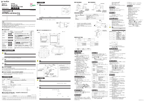
■DC 继电器接线 ■AC 继电器接线●端子盖该手册对调节器的安装,接线等运行前的准备工作进行说明。
目 录1.仪器的安全使用说明2.型号和规格代码3.如何安装4.正确接线方法5.硬件规格6.端子接线图介绍感谢您购买UP550程序调节器本调节器在出厂的还有还有7张A2大小的用户手册和1张CD-ROM 。
这7张印刷品形式的用户手册,讲述了进行基本操作的步骤(单回路控制:出厂时已设定)。
建议参考这些用户手册,理解调节器的[1]安装,[2]初始设定,[3]操作步骤。
CD-ROM 版的用户手册应用篇,对于各功能的结合和根据需要进行的设定作出了进一步说明,也记述了单回路控制以外的操作说明和用户手册应用篇。
另外,通过另购的参数设定工具(型号:LL100)能够容易地设定和改变参数。
■如何使用手册1.仪器的安全使用说明在调节器上指明的下述符号确保使用安全。
调节器上的该符号表示操作者必须按照用户手册上的说明进行操作,以免受伤,危及人生安全或者损坏仪器。
在手册上讲述了操作人员应该如何训练特殊的注意力以避免触电或者有受伤或者危及生命的事件发生。
下述符号是在用户手册和用户手册应用篇(CD-ROM 版)中使用。
如果正常操作硬件或者软件,则会导致硬件或软件的损坏或者系统失败。
对于那些有助于理解调节器操作和特性的内容,请引起注意。
■关于本产品的免责使用本产品之前,请仔细阅读注意事项。
对于违反注意事项所引起的机器的故障,我公司不承担任何责任以及保修。
此外,由于使用不当对客户以及第三者所造成的直接或间接的损伤、或者由于使用不当导致产品的损坏,本公司不承担任何责任。
■有关本产品的维护、安全以及改造的注意事项(1)为了维护本产品以及本产品控制系统的安全,请严格按照该说明书中的安全事项进行操作。
如果违反安全事项进行操作。
本公司不保证产品的安全性。
(2)严禁对本产品进行改造。
2.型号和规格代码在使用调节器以前,请确认型号和规格代码是否正确。


QUICK START for DOS SAMPLE SOURCE and HARDWARE REFERENCE CARDRocketPort550RangeRocketPort550Universal RangeBroadPort550RangeThis Guide.Comtrol GmbH Document Number COM229DOSRelease Rev D17th December2007MS DOS Sample source release V1.101.Before you begin (3)2.Extracting the driver files to the PC’s hard disk (3)3.Installing Your RocketPort/BroadPort550hardware (4)4.Enumerating the RocketPort/BroadPort550for use under a Windows9x DOS session (5)5.Verifying operation (6)6.RocketPort/BroadPort550Removal (6)7.RocketPort550,RocketPort550Universal&BroadPort550Connector Pin-outs (7)8Technical Support (15)9.Specifications (16)10.Trademarks (18)1.Before you beginV1.10and above of the DOS sample software supports the originalRocketPort/BroadPort550range,the RocketPort/BroadPort550Universal range and the new BroadPort550Universal RS422SMPTE cards.When this document refers to RocketPort/BroadPort550it is relevant to the RocketPort/BroadPort550,the RocketPort/BroadPort550Universal controller and the BroadPort550cards.If the text is relevant to only one controller type then the reference will be to the‘RocketPort/BroadPort550Universal’,‘original RocketPort/BroadPort550’or BroadPort550.The MS DOS sample source code for the RocketPort/BroadPort550is supplied as a self extract file.The sample source code is intended for use with standard MS DOS.It can also be used in a DOS session under Windows9x.It will work with a singleRocketPort/BroadPort550controller,however developers are free to modify the code for operation with multiple RocketPort/BroadPort550cards.This software’s primary purpose is to assist DOS developers in the porting of their existing Hostess450/550register level driver software to the RocketPort/BroadPort 550.The sample source,as supplied,builds a simple application called‘TERM’EXE’.NOTE:The DOS sample source code accesses the RocketPort/BroadPort550 controller at the register I/O level.Executable code produced using these techniques cannot be used under Windows NT,XP or2000.Prior to installing the RocketPort/BroadPort550controller,the driver files must be extracted to a folder on your PC’s hard disk.2.Extracting the driver files to the PC’s hard diskTerminology<cr>means press the enter key.The term‘directory’will be used which is synonymous with a Windows‘folder’The following assumes that you are running MS DOS or a DOS session under Windows9x.If running under Windows,then you may,of course,use Windows Explorer to create a working folder and copy/paste files.1.Create a working directory on your PC’s hard disk eg.,md c:\r550DOS<cr>2.Copy the zipped file R550DOS.EXE,from the CD to the directory created instep1.copy d:\DOSSMPL\dos550.exe c:\r550DOS<cr>Step2assumes that you are installing from a distribution CD with a driver letter d:Replace this with the driver letter for your CD ROM drive,if it is different.Step2also assumes that the destination working directory is c:\r550DOS.You should enterthe path to the working directory that you entered in step1,if it is different.If you have downloaded the file from Comtrol’s web site then copy it from your downloadfolder to the Dos sample working directory.3.Unzip the files by running dos550.execd\r550DOS<cr>dos550<cr>3.Installing Your RocketPort/BroadPort550hardwareTake care when you handle the RocketPort/BroadPort550PCI cards,like any electronic device,they are sensitive to static e normal static precautions such as wearing an earth ground strap.Hardware InstallationPower down the host PC and disconnect its mains input.Follow the host PC manufacturer instructions describing how to access the PC in order to install additional cards.Ensure the RocketPort/BroadPort550back plate retaining screw is fitted.Follow the host PC instructions for re assembly of the host PC it’s cabling and re-fitting of safety covers.Re-connect the host PC mains input and power up the PC.If you are using the RocketPort/BroadPort550from a Windows9x DOS session then the controller hardware will need to be enumerated by Windows,proceed to section4, enumerating the RocketPort/BroadPort550.If you are using MS DOS then proceed to section5,verifying operation.4.Enumerating the RocketPort/BroadPort550for use under a Windows9x DOS session.The RocketPort/BroadPort550controllers require bus enumeration so that they can be accessed from a Windows9x DOS session.The procedure is similar to installing a Windows9x driver,and the term‘driver’is used however no software is actually installed(or needs to be at this stage).The controllers are simply made known to Windows 9x..1.In the previous section you installed the RocketPort/BroadPort550and powered up the PC2.Windows will detect the new hardware at power up and display the:"Add New Hardware Wizard"dialog Window.Click Next3.The next dialog window asks:Search for the best driver for your device.(Windows Default)orDisplay a list of all the drivers in a specific location,so you can select the driveryou want.ENSURE THAT SEARCH IS SELECTEDClick Next4.The next dialog window asks where to search for the Driver.Select Specify a locationEnter C:\R550DOS into the dialog WindowIf you extracted the driver files to an alternative folder then replace the above path with thealternative path for the RocketPort/BroadPort550DOS files.5.Windows will search the folder for the DriverWhen found,the dialog displays the path to the generic‘inf’file r550dos.infClick Next6.On completion,Windows will display the‘Finished Installing dialog window’Click Finish.5.Verifying operationThe MS DOS sample code,consists of a number of‘C’source files,headers etc.Theprimary purpose is to provide examples for developers in order to assist them in porting their register level drivers from the Hostess450/550ISA range to theRocketPort/BroadPort550series.A Make file is provided for Borland C/C++3.1along with various environment setting batch files.The files,unmodified can be used to build a simple application called‘TERM.EXE’.This application can be used to verify the controller installation.1.Change to the R550DOS working directory.cd\r550dosIf you extracted the driver files to an alternative folder then replace the above path with thealternative path for the RocketPort/BroadPort550DOS sample files.2.Place a loopback plug into the port to test.3.Run the application.term<cr>follow the‘on screen’instructions,to select the port to test and whether localecho is required.Press a key,the character should be echoed to the screen either once(no localecho)or twice(local echo).6.RocketPort/BroadPort550RemovalSimply delete the files in the working directory C:\r550dosIf you extracted the driver files to an alternative folder then replace the above path with the alternative path for the driver files.Shut down and power off the PC prior to accessing the PC in order to remove the RocketPort/BroadPort550controller(s).Follow the host PC manufacturer instructions describing how to access the PC in order to remove adapter cards.Follow the host PC instructions for re assembly of the host PC its cabling and re-fitting of safety covers.7.RocketPort550,RocketPort550Universal&BroadPort550Connector Pin-outsRocketPort5504QuadRocketPort550Universal4MiniRocketPort5504RJ45,RocketPort550Universal4RJ45RocketPort5508OCTA,RocketPort550Universal8OCTARocketPort5508RJ11,RocketPort550Universal8RJ11BroadPort5508Universal(RS422SMPTE)BroadPort55016Universal(RS422SMPTE)RocketPort5508Port(with dedicated interface box)*RocketPort55016Port(with dedicated interface box)**Includes RocketPort550Universal4,8&16PortRocketPort5504Quad Cable-37way D type fan out to4DB25MaleDB37pin DB25pin RS232Signal/Port DB37pin DB25pin RS232Signal/Port 352TxD Port0262TxD Port2343RxD Port0253RxD Port2164RTS Port074RTS Port2175CTS Port085CTS Port2156DSR Port066DSR Port2377Signal Gnd Port0287Signal Gnd Port2 338DCD Port0248DCD Port23620DTR Port02720DTR Port21822RI Port0922RI Port2122TxD Port132TxD Port3113RxD Port123RxD Port3304RTS Port1214RTS Port3315CTS Port1225CTS Port3296DSR Port1206DSR Port3147Signal Gnd Port157Signal Gnd Port3 108DCD Port118DCD Port31320DTR Port1420DTR Port33222RI Port12322RI Port3Pin19of the37way connector is not usedPins1,9,10,11,12,13,14,15,16,17,18,19,21,23,24and25of each25way connector are not used.The cable shields and connector metal bodies should be connected.19RocketPort550Universal4MINI Cable-44way HD type fan out to4DB9Male DB44pin DB9pin RS232Signal/Port DB44pin DB9pin RS232Signal/Port 23TxD Port0253TxD Port2172RxD Port0392RxD Port2327RTS Port097RTS Port2188CTS Port0408CTS Port216DSR Port0246DSR Port2195Signal Gnd Port0415Signal Gnd Port2 311DCD Port081DCD Port2334DTR Port0104DTR Port239RI Port0269RI Port2363TxD Port1133TxD Port352RxD Port1282RxD Port3217RTS Port1437RTS Port368CTS Port1298CTS Port3356DSR Port1126DSR Port375Signal Gnd Port1305Signal Gnd Port3 201DCD Port1421DCD Port3224DTR Port1444DTR Port3379RI Port1149RI Port3RocketPort 5508OCTA Cable -78way D type fan out to 8DB25Male DB78Pin DB25Pin RS232Signal/Port DB78Pin DB25Pin RS232Signal/Port302TxD Port 0402TxD Port 4553RxD Port 0283RxD Port 4514RTS Port 0214RTS Port 4165CTS Port 0255CTS Port 4546DSR Port 056DSR Port 4717Signal Gnd Port 0757Signal Gnd Port 4358DCD Port 0438DCD Port 44920DTR Port 02220DTR Port 43622RI Port 04422RI Port 4502TxD Port 122TxD Port 5173RxD Port 183RxD Port 5314RTS Port 1414RTS Port 5535CTS Port 145CTS Port 5346DSR Port 1426DSR Port 5727Signal Gnd Port 1767Signal Gnd Port 5338DCD Port 1238DCD Port 53220DTR Port 1320DTR Port 51522RI Port 12422RI Port 5112TxD Port 2632TxD Port 6373RxD Port 2463RxD Port 6124RTS Port 2624RTS Port 6595CTS Port 295CTS Port 6586DSR Port 2296DSR Port 6737Signal Gnd Port 2777Signal Gnd Port 6398DCD Port 2488DCD Port 61320DTR Port 26120DTR Port 62022RI Port 24722RI Port 6102TxD Port 3642TxD Port 7563RxD Port 3273RxD Port 7144RTS Port 3604RTS Port 7575CTS Port 3455CTS Port 7386DSR Port 3266DSR Port 7747Signal Gnd Port 3787Signal Gnd Port 7188DCD Port 368DCD Port 75220DTR Port 3120DTR Port 71922RI Port 3722RI Port 7Pin 67of the 78way connector is not used.Pins 65,66,68,69and 70are Signal Ground.Pins 1,9,10,11,12,13,14,15,16,17,18,19,21,23,24and 25of each 25way connector are not used.The cable shields and connector metal bodies should be connected.121406020395978RocketPort 5508RJ11Cable Pin Out RJ11pinRS232Signals 1DTR 2Signal Ground 3TxD 4RxD 5DCD 6CTS RocketPort 5504RJ45Cable Pin Out RJ45pinRS232Signals 1RTS 2DTR 3Signal Ground 4TxD 5RxD 6DCD 7DSR 8CTS RocketPort 5508Port -with 8DB25Female RS232dedicated interface box andRocketPort 55016Port -with 16DB25Female RS232dedicated interface boxDB25Female Interface Box Connector DB25Male Connector RJ11Plug front and side viewRJ45Plug front and sideview11413251325114Rocket Port Interface Box DB25SignalsUniversal Interface DB25Pin RS232Signal RS422Signal(RocketPortRS232/422version only)2TxD*See note See UI manual3RxD*See note See UI manual4RTS*See note See UI manual5CTS*See note See UI manual6DSR*See note See UI manual7Signal Gnd*See note See UI manual8DCD*See note See UI manual20DTR*See note See UI manual15Not used RxD+RxD(B)See UI manual17Not used RxD-RxD(A)See UI manual19Not used TxD+TxD(B)See UI manual25Not used TxD-TxD(A)See UI manual*Note:All RS232signals are present in RS422mode.The RocketPort interface box can only be used with the RocketPort550-8and RocketPort550-16.These controllers have a single DB25F mounted on the backplate which connects via the RocketPort cable to the interface box.Alternatively the RocketPort550-8and550-16controllers may connect to the Comtrol Universal Interface(UI).Refer to the UI manual for connector pin-outs.The Quad,Octa,RJ11and RJ45RocketPort versions do not support RS422mode. Pins1,9,10,11,12,13,14,21,22,23and24of each25way connector are not used. BroadPort550Each port of the BroadPort550can be configurated to be BUS controller or Tributary (SMPTE STANDARD207M-1997).The user can select for each port the configuration using2DIP switches.The DIP switch S1has8switches and control the ports1-8.The DIP switch S2has8switches and controls the ports9-15.The next tables shows S1S2BroadPort550DIP SWITCH S1DIP SWITCH S1Functionswitch1closed(open)Port8is BUS controller(Tributary)switch2closed(open)Port7is BUS controller(Tributary)switch3closed(open)Port6is BUS controller(Tributary)switch4closed(open)Port5is BUS controller(Tributary)switch5closed(open)Port4is BUS controller(Tributary)switch6closed(open)Port3is BUS controller(Tributary)switch7closed(open)Port2is BUS controller(Tributary)switch8closed(open)Port1is BUS controller(Tributary)BroadPort550DIP SWITCH S2DIP SWITCH S2Functionswitch1closed(open)Port16is BUS controller(Tributary) switch2closed(open)Port15is BUS controller(Tributary) switch3closed(open)Port14is BUS controller(Tributary) switch4closed(open)Port13is BUS controller(Tributary) switch5closed(open)Port12is BUS controller(Tributary) switch6closed(open)Port11is BUS controller(Tributary) switch7closed(open)Port10is BUS controller(Tributary) switch8closed(open)Port9is BUS controller(Tributary) BroadPort550(16ports)Interface SCSI68SignalsSCSI68 Pin RS422Signals(Tributary)RS422Signals(BUS controller)1RxD_B Port1TxD_B Port1 2RxD_A_Port1TxD_A_Port1 3TxD_B Port1RxD_B Port1 4TxD_A Port1RxD_A Port1 5RxD_B Port2TxD_B Port2 6RxD_A_Port2TxD_A_Port2 7TxD_B Port2RxD_B Port2 8TxD_A Port2RxD_A Port2 9RxD_B Port3TxD_B Port3 10RxD_A_Port3TxD_A_Port3 11TxD_B Port3RxD_B Port3 12TxD_A Port3RxD_A Port3 13RxD_B Port4TxD_B Port4 14RxD_A_Port4TxD_A_Port4 15TxD_B Port4RxD_B Port4 16TxD_A Port4RxD_A Port4 17RxD_B Port5TxD_B Port5 18RxD_A_Port5TxD_A_Port5 19TxD_B Port5RxD_B Port5 20TxD_A Port5RxD_A Port5 21RxD_B Port6TxD_B Port6 22RxD_A_Port6TxD_A_Port6 23TxD_B Port6RxD_B Port6 24TxD_A Port6RxD_A Port6 25RxD_B Port7TxD_B Port7 26RxD_A_Port7TxD_A_Port7 27TxD_B Port7RxD_B Port7 28TxD_A Port7RxD_A Port7 29RxD_B Port8TxD_B Port8 30RxD_A_Port8TxD_A_Port8 31TxD_B Port8RxD_B Port832TxD_A Port 8RxD_A Port 833RxD_B Port 9TxD_B Port 934RxD_A_Port 9TxD_A_Port 935TxD_B Port 9RxD_B Port 936TxD_A Port 9RxD_A Port 937RxD_B Port 10TxD_B Port 1038RxD_A Port 10TxD_A Port 1039TxD_B Port 10RxD_B Port 1040TxD_A Port 10RxD_A Port 1041RxD_B Port 11TxD_B Port 1142RxD_A Port 11TxD_A Port 1143TxD_B Port 11RxD_B Port 1144TxD_A Port 11RxD_A Port 1145RxD_B Port 12TxD_B Port 1246RxD_A Port 12TxD_A Port 1247TxD_B Port 12RxD_B Port 1248TxD_A Port 12RxD_A Port 1249RxD_B Port 13TxD_B Port 1350RxD_A Port 13TxD_A Port 1351TxD_B Port 13RxD_B Port 1352TxD_A Port 13RxD_A Port 1353RxD_B Port 14TxD_B Port 1454RxD_A_Port 14TxD_A_Port 1455TxD_B Port 14RxD_B Port 1456TxD_A Port 14RxD_A Port 1457RxD_B Port 15TxD_B Port 1558RxD_A_Port 15TxD_A_Port 1559TxD_B Port 15RxD_B Port 1560TxD_A Port 15RxD_A Port 1561RxD_B Port 15TxD_B Port 1562RxD_A_Port 15TxD_A_Port 1563TxD_B Port 15RxD_B Port 1564TxD_A Port 15RxD_A Port 1565GNDGND6667GNDGND68SCSI 68connector front viewPin 1Pin 2Pin PinBroadPort550IF DB9signalsDB9Pin RS422signal(Tributary)RS422signal (BUS controller)1Frame Ground Frame Ground6GND(TxD signal common)GND(RxD signal common) 2TxD_A RxD_A7TxD_B RxD_B3RxD_B TxD_B8RxD_A TxD_A4GND(RxD signal common)GND(TxD signal common) 9Frame ground Frame ground5N/A N/A8Technical SupportComtrol has a staff of support technicians available.Telephone support is available daily, Monday through Friday(except holidays)on the US(Central Time)or UK number listed below.Before you call please have the following information available:Item Your System Information RocketPort550RocketPort550UniversalBroadPort550UniversalModel numberRocketPort550RocketPort550UniversalBroadPort550UniversalSerial numberRocketPort550RocketPort550UniversalBroadPort550UniversalDevice driver versionInterface typeOperating system type and releasePC make,Model and speedDetails of other cards configured in the PCComtrol GmbHUnit2,Staplehurst Business ParkWeston on the GreenBicesterOxfordshireOX253QUGreat BritainPhone:+44(0)1869352740Fax:+44(0)1869351858Email:******************.ukWeb site:Comtrol Corporation6655Wedgwood RoadSuite120MinneapolisMN55311-3646USAPhone:+17634944100Fax:+17634948992Email:*******************Web site:FTP site:telnet:9.SpecificationsRocketPort550&RocketPort550Universal SpecificationBaud rate:RP550PCI4(RJ45and QUAD)50to460.8K baudRP550PCI8(RJ11and OCTA)50to115.2K baudRP550PCI8and16Port(uses interface box)50to230.4K baudRP550UPCI4(RJ45and QUAD)50to115.2K baudRP550UPCI8(RJ11and OCTA)50to115.2K baudRP550UPCI8and16Port(uses I/F box)50to230.4K baudNote:Throughput(CPS)is dependant upon platform,operating system&application s/w Bus interface32Bit PCI(5V)UPCI(5V&3.3V)Control by device driverData bits5,6,7or8Parity Odd,Even,Mark,Space or None Stop bits1,1.5,or2Note:Certain combinations of data bits,parity or stop bits may not be allowed by some operating systems.BroadPort550Universal SpecificationBaud rate:BP550UPCI8(SMPTE)50to230.4K baudBP550UPCI16(SMPTE)50to230.4K baudNote:Throughput(CPS)is dependant upon platform,operating system&application s/w Bus interface UPCI(5V&3.3V)Control by device driverData bits5,6,7or8Parity Odd,Even,Mark,Space or None Stop bits1,1.5,or2Note:Certain combinations of data bits,parity or stop bits may not be allowed by some operating systems.Environmental Condition SpecificationAir temperature:System on0to40ºCSystem off-20to85ºCHumidity(non-condensing)System on8to80%System off20to80%Altitude0to10,000feetMTBF Greater than30yearsProduct5V Current+12V Current-12V Current RocketPort5504Quad210mA20mA20mA RocketPort5504RJ45190mA20mA20mA RocketPort5508OCTA140mA120mA120mA RocketPort5508RJ11250mA80mA80mA215mA0mA0mA RocketPort5508PortSee note*300mA0mA0mA RocketPort55016PortSee note*Product5V Current+12V Current-12V Current RocketPort550Universal4260mA200mA200mARJ45280mA200mA200mA RocketPort550Universal4Mini400mA400mA400mA RocketPort550Universal8OCTARocketPort550Universal8315mA260mA260mARJ11400mA0mA0mA RocketPort550Universal8Port See note*RocketPort550Universal600mA0mA0mA16Port See note**Note the current figures are for the card only and do not include the attached interface box. Refer to the manual for the RocketPort or Universal interface boxes for current consumption figures and addto the above.Product5V Current+12V Current-12V Current BroadPort550Universal8250mA N/A N/A BroadPort550Universal16300mA N/A N/A10.TrademarksCopyrightCopyright2007Comtrol GmbH All rights reserved.Product names mentioned in this document may be trademarks and/or registered trademarks of their respective companies.Microsoft,MS-DOS,MS,Windows,Windows NT,Windows95,Windows98,MSN, MSDN and Visual C++are registered trademarks of Microsoft Corporation.“Acrobat®Reader Copyright©1987-2001Adobe Systems Incorporated.All rights reserved.Adobe and Acrobat are trademarks of Adobe Systems Incorporated which may be registered in certain jurisdictions”Comtrol reserves the right to make product and user guide changes without notice Comtrol makes no representations or warranties with regard to the contents of this Quick Start Card or to the suitability of any Comtrol product for any particular purpose. Specifications are subject to change without notice.Some software or features may not be available at the time of publication.Contact your reseller for current product information.。

文档编号 版本 密级 PRONET-S002 V1.01内部公开 南京埃斯顿自动控制技术有限公司研发部资源类别:共25页PROFIBUS-DP 用户手册拟制: 日期: 审核: 日期: 批准: 日期:修订记录日期 修订版本 描述 作者 2008/08/28 1.00 初稿完成 徐慧2009/09/14 1.01 Profibus-DPV0, DPV1 , DPV2合并在DP100模块的一个DSP程序。
易健第一章:前言本说明书内容主要介绍PROFIBUS接线,配置,功能和软件协议。
z第二章:PROFIBUS简介z第三章:产品概述z第四章:安装信息z第五章:PROFIBUS-DP通讯z第六章:GSD文件说明及参数设定z第七章:LED灯指示说明及故障排除方法z第八章:参数模式/对象字典z第九章:参数描述第二章:PROFIBUS 简介2.1 PROFIBUS 概况PROFIBUS是一个国际化、开放性且独立于供货商的(vendor-independent)通讯协议标准,广泛应用于生产、制造、加工和建筑自动化以及其它自动化控制领域。
PROFIBUS 根据不同需求及应用,有三种主要类型:PROFIBUS-DP、PROFIBUS-PA及PROFIBUS-FMS:z PROFIBUS-DP(Decentralized Periphery):PROFIBUS-DP是一种速率快且成本低的通讯系统,专为高速数据传输而设计的。
PROFIBUS-DP被广泛使用,尤其在远程I/O系统、马达控制中心以及变频器的应用上。
采用PROFIBUS-DP连接自动化系统与分散外围装置间通讯时,可达到最佳化的效果。
z PROFIBUS-PA(Process Automation):PROFIBUS-PA(通常附有 MBP-IS 传输技术)是一种用于过程自动化的PROFIBUS通讯系统,PROFIBUS-PA以PROFIBUS-DP为基础,在数据传输上为PROFIBUS-DP通讯协议的延伸,专门支持本质安全防爆应用,可藉由本质安全防爆MBP-IS接口,应用在有爆炸危险的区域。

用户手册电烤箱KODDP71XC伊莱克斯 - 想你所想!感谢您选购伊莱克斯设备。
您选择的产品将数十载的专业经验与创新特色融为一体。
它的设计注重客户体验,兼具精巧和时尚的特点。
无论何时使用,都能确保您获得满意的效果。
欢迎使用伊莱克斯产品。
访问我们的网站:获取使用建议、手册、故障检修工具、检修信息:客户关怀与服务务必使用原装备件。
当您联系授权服务中心时,请确保您可以提供以下数据:型号、产品编号、序列号。
该信息可以在标牌上找到。
警告/注意 - 安全信息一般信息和提示环境信息如有更改恕不另行通知。
内容1. 安全信息 (2)2. 安全说明 (4)3. 安装 (6)4. 产品说明 (8)5. 控制板 (8)6. 首次使用前 (9)7. 日常使用 (9)8. 时钟功能 (11)9. 配件使用方法 (13)10. 附加功能 (15)11. 提示和技巧 (16)12. 保养与清洗 (18)13. 排除故障 (23)14. 能效 (24)15. 维修服务指南 (24)16. 环保问题 (26)1. 安全信息请确保按照随附说明操作本机,否则可能发生安全事故。
在安装和使用本机之前,请认真阅读随附的操作说明。
对于不当安装或使用本机而造成的任何伤害或损害,制造商不承担任何责任。
请妥善保管操作说明,并置于易于取用的地方,供将来参考之用。
2中文1.1 未成年人和弱势群体安全•年龄在 8 岁以下的未成年人不得使用本电器。
本电器可供 8岁及以上未成年人和存在身体缺陷、感官或精神障碍或缺乏相关经验及知识的人士使用,前提是由具备安全使用本机经验和知识并了解相关危险的监护人为其提供监督或指导。
•未成年人和存在身体缺陷、感官障碍或精神障碍的人士应远离本电器,除非身边有监护人持续监督。
•应对青少年加强看管,确保他们不将本电器当做玩具。
•确保未成年人远离洗涤剂。
•本电器正在运行或冷却时,请勿让未成年人和宠物靠近。
可触及的部件温度很高。
•所有包装物都必须远离未成年人,且予以妥善处置。


GROUP550设备说明书目录一、设备环境安装要求 (3)1、硬件规格 (4)2、网络需求 (4)二、设备安装步骤 (4)1、GROUP 550介绍-设备组成: (5)2、GROUP 550介绍-背板连线示意: (5)3、实物展示 (5)4、物理连接 (6)三、加电测试 (15)1、设备开机 (15)2、电源指示灯状态 (15)3、主屏幕显示状态 (15)四、设备系统配置 (16)1、系统开机配置 (16)2、遥控器操作方法 (21)3、呼叫对方 (22)4、高级进阶设置 (23)五、系统功能测试 (28)1、终端点对点呼叫是否能够联通 (29)2、终端多点呼叫是否能够联通 (29)3、终端输出内容画面是否为1080P (29)4、终端画面和音频是否唇音同步 (29)5、终端双流输入是否正常 (29)六、设备常见故障处理 (29)1、遥控器的充电 (29)2、设置预设位和调用 (30)3、麦克风状态指示灯 (31)4、双流的发送 (31)5、诊断: (32)6、会议常见问题 (33)7、系统维护 (35)一、设备环境安装要求1、硬件规格2、网络需求视频会议系统传输使用中国建设银行专用IP网,由于MCU是整个视频会议系统的汇聚中心,为了保证视频会议画面清晰、声音逼真,并确保中国建设银行内网与视频会议系统的安全、稳定运行,建议如下:1)为视频设备单独划分内网,使用单独Vlan。
2)MCU、录播服务器、会管服务器和设备管理服务器等设备需要连接在内网核心交换机上。
3)各个会议室视频终端到MCU之间尽量减少网络节点,避免受内网用户业务影响。
4)MCU、录播服务器、会管服务器和设备管理服务器及各个会议室视频终端均可与出资企业视频终端通信。
其间不经过防火墙、流量控制等设备。
如必需经过,需打开相关策略保证视频业务可通信。
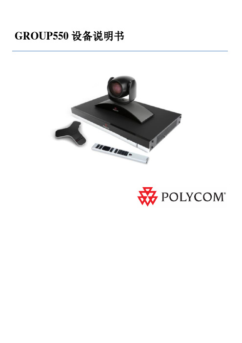
二、设备安装步骤1、GROUP 550介绍-设备组成:称风实物图2、GROUP 550介绍-背板连线示意:3、实物展示4、物理连接4.1 摄像机连接4.2 双流输入4.3 音频输入4.4 音频输出音频输出接口,双声道4.5 视频输出4.6 网络接口4.7 电源接口三、加电测试1、设备开机2、电源指示灯状态开机后电源灯为蓝色状态待机状态电源灯为橙色色状态蓝色橙色闪烁交替闪烁则是主机处于升级状态3、主屏幕显示状态四、设备系统配置1、系统开机配置1.1 用遥控器选择“简体中文”1.2 选择“高级”1.3 选择“接受”1.4 选择”China”1.5 第五页系统名使用默认名称(或自行更改),然后点击”下一个”1.6 配置的设备地址,先选择手动输入IP地址,使用遥控器一次输入IP地址、网关、掩码。