英语原文:
Integrated Machine and Control Design
Abstract—In this paper, we describe a systematic design procedure for reconfigurable machine tools and their associated control systems. The starting point for the design is a set of operations that must be performed on a given part or part family. These operations are decomposed into a set of functions that the machine must perform and the functions are mapped to machine modules, each of which has an associated machine control module. Once the machine is constructed from a set of modules, the machine control modules are connected. An operation sequence control mod ule, user interface control module, and mode-switching logic complete the control design. The integration of the machine and control design and the reconfigurability of the resulting machine tool are described in detail.
I. Introduction
In today’s competitive markets, manufacturing systems must quickly respond to changing customer demands and diminishing product life cycles. Traditional transfer lines are designed for high volume production, operate in a fixed automation paradigm, and therefore cannot readily accommodate changes in the product design. On the other hand, conventional CNC-based “flexible” manufacturing system offer generalized flexibility but are generally slow and expensive since they are not optimized for any particular product or a family of products.
An effort at the University of Michigan aims to develop the theory and enabling technology for reconfigurable machining systems. Instead of building a machining system from scratch each time a new part is needed, an existing system can be reconfigured to produce the new part. In this paper, we describe how an integrated machine and control design strategy can result in machine tools which can be quickly and easily configured and reconfigured.
In order to provide exactly the functionality and capacity needed to process a family of parts, RMTs are designed around a given family of parts. Given a set of operations to be performed, RMTs can be configured by assembling appropriate machine modules. Each active module in the library has a control module associated with it. As the mechanical modules are assembled, the control modules will be connected and the machine will be ready to operate. Extensive and time-consuming specialized control system design will not be required. Section II describes how the machine is designed from a set of basic machine modules,
This research was supported in part by the NSF-ERC connected in a well-defined fashion, and Section III describes how the control is similarly assembled from a library of control modules. This modular construction of the machine and control allows for
many levels of reconfigurability as described in Section IV. The paper concludes with a description of future work in Section V.
II. Machine Design
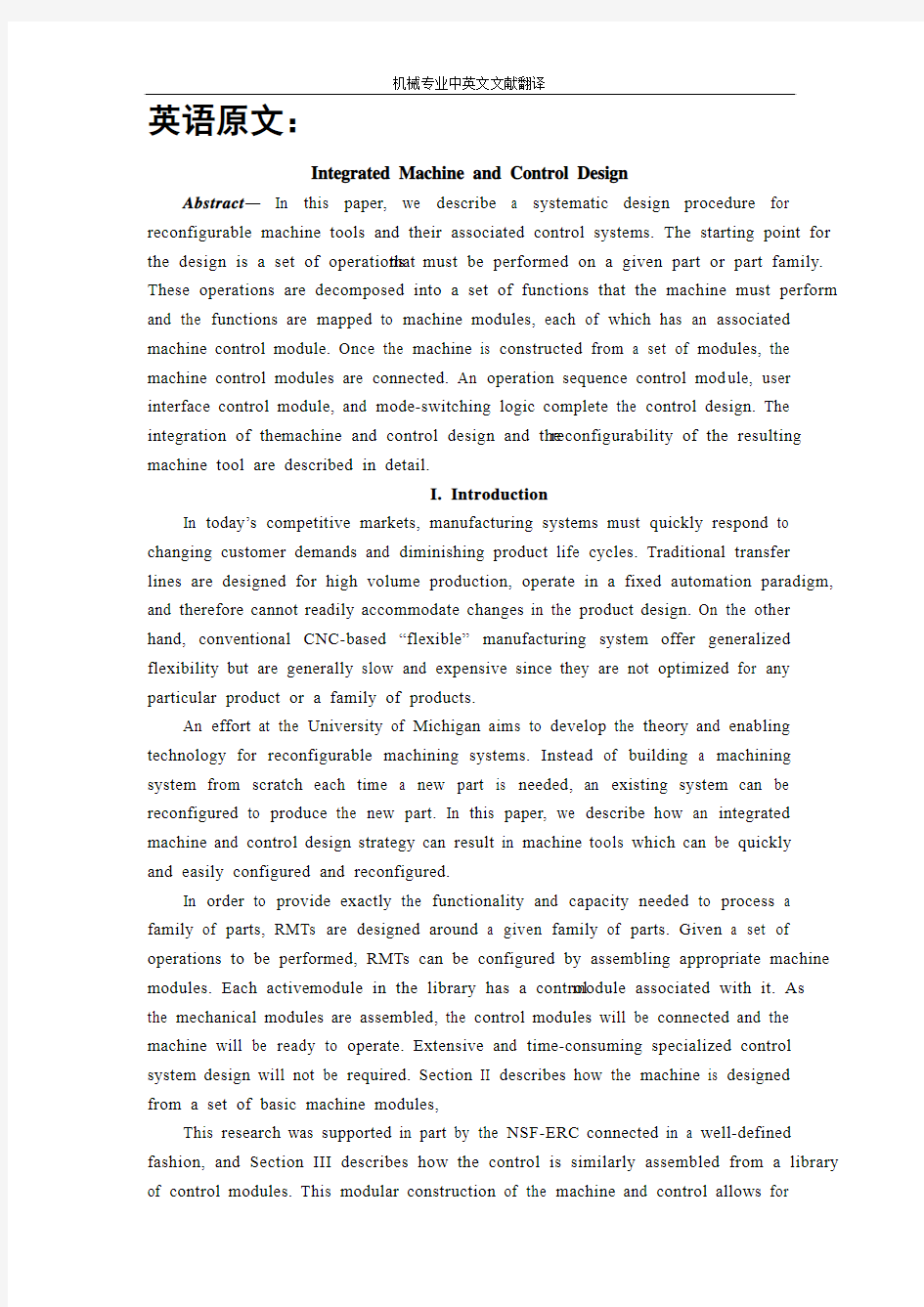
Ongoing work on manufacturing system configuration at the University of Michigan addresses the problem of starting from a part (or part family) description and extracting the machining operations necessary to produce the part(s). The operations are grouped according to tolerance, order of execution, and desired cycle time of the system, with the intention that each operation “cluster” can be produced on a single machine tool. The operation cluster considered here is to drill a set of holes for the cam tower caps on V6 and V8 cylinder heads shown in Figure 1. The input to the reconfigurable machine tool design procedure is the cutter location data generated by a process planner for this operation cluster. data includes positioning and drilling information.
The RMT design procedure consists of three main stages: task clarification, module selection, and evaluation. After a brief literature review, these three stages will be outlined in this section.
A. Related research
Since reconfigurability is a relatively new concept in ma chining systems, there is little, if any, published literature on the design of reconfigurable machine tools. However, modular machine tools have been on the market for several years, and some of the published articles on modular robots, modular machines and assembly do have some rel-evance to the design of reconfigurable machine tools. For example, Shinno and Ito proposed a methodology for generating the structural configuration of machine tools. They decomposed the machine tool structures into simple geometric forms: e.g. boxes, cylinders, etc. Yan and Chen [21], [1] extended this work to the ma chining center structural design. [12] adapted Ito’s method for modular machine t ool synthesis and de-veloped a method for enumerating machine tool modules. Paradis and Khosla [15] determined the modular assembly configuration which is optimally suited to perform a specific task. On the systems front, Rogers and Bottaci [16] discussed the significance of reconfigurable manufacturing systems, and Owen et al. [13] developed a modular reconfigurable manufacturing system synthesis program for educational pur poses.
In our work, traditional methods of motion representation and topology (i.e. screw theory, graph theory, etc.) are employed to capture the characteristics of RMTs. These mathematical schemes are used for topological synthesis, function-decomposition, and mapping procedures; details can be found in [9].
Figure 1
B.Task clarification
The design of an RMT begins with task clarification, which entails analyzing the cutter location data to determine the set of functions which are necessary to accomplish the desired kinematic motions. There are three steps. First, graphs are generated which abstractly representation
Fig. 3. High-level operation sequence, showing causal dependencies and concurrencies.
This abstract representation of the sequence of operations is derived from the CL data, and will be used to design the sequencing control the motions. These graphs are then decomposed into functions, and finally the functions are mapped onto machine modules which exist in the library.
A graph representation of the machine tool structure allows for systematic enumeration of alternate configurations and also provides a method of identification of nonisomorphic graphs. The graph representation is also used for bookkeeping to assign machine modules to the graph elements. A graph consists of a set of vertices connected together by edges. In using a graph as an abstract represen tation of a machine tool structure, we define two different types of vertices: type 0 and type 1. A vertex represents a physical object with two ports; each port represents the location on the object where it can be attached to a neighboring object. A type 0 vertex has input and output ports that are in-line with respect to each other, whereas a type 1 vertex has input and output ports that are perpendicular to each other. Machining tasks are also classified as type 0 or type 1, depending on whether the tool is parallel or per pendicular to the workpiece.
C. Module selection
Commercially available modules are selected from the module library for each of
the functions (structural as well as kinematic) that were mapped to the graph in the task clarification stage. The data stored for each module in the library includes the homogenous transformation matrix representing its kinematic or structural function, the twist vector supplemented by range of motion information, a compliance matrix representing the module stiffness, module connectivity information, and power requirements (for active modules such as spindles and slides).
The first step in module selection is to compare the homogeneous transformation matrices of the modules with the task requirement matrix such that when appropriate modules are selected to meet the task requirements, the product of all module matrices should be equal to the desired task matrix: T = T1· T2 · · · Tn. Again, there may be many possible choices of modules for a given structural configuration. Figure 6 shows how different slides, spindles, and structural elements can be assembled according to the graph of Figure 4.
A slide module, with its CAD model and transformation matrix, is shown in Figure
7. It is capable of one direction of linear motion, indicated by the ~1 variable in its transformation matrix. Its database entry, shown in Table I, stores not only its transformation matrix but also the manufacturer name, model number, initial position, power level, and motion data. The twist vector is augmented by information on the minimum, initial, and maximum displacement of the module.
TABLE I
Database information and documentation for the machine
module shown in Figure 7.
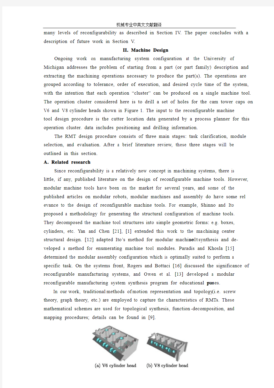
(a) V6 machine (b) V8 machine
Fig. 2. Reconfigurable machine tool designs for the two different parts.
D. Evaluation
Once a set of kinematically-feasible modules have been selected, the resulting machine design must be evaluated. The criteria for evaluation of the reconfigurable machine tools synthesized by the above systematic procedure include the work envelope, the number of degrees of freedom, the number of modules used, and the dynamic stiffness.
The number of kinematic degrees of freedom of the machine tool must be kept to a minimum required to meet the requirements, both to reduce the actuation power and minimize the chain of errors. Machine tool designs which are generated using this methodology for the example parts of Figure 1 are shown in Figure 8.
The resulting designs must be evaluated with respect to the expec ted accuracy. The stiffness of the entire machine tool, one of the most important factors in performance, is estimated based on the module compliance matrices and the connection method.
III. Control Design
As the machine is built from modular elements, so is the control. In this work, we focus on the logic control for sequencing and coordination of the machine modules; a discrete-event system formalism is used [6]. There is one control module associated with each active machine module; we refer to these as machine control modules. In the machine design, there are passive elements which connect the active elements together. In the control design, there must also be“glue” modules which connect the machine control modules. The overall architecture of the control system for an RMT is shown in Figure 9.The structure is similar for either of the two machines shown in Figure 8; for the V8 machine, there is no Y -axis control module. As shown, the machine control modules are at the lowest level; these interact directly with the mechanical system. Three modules handle the mode switching logic. In this section, we briefly describe each of these types of control modules as well as their interaction and coordina tion.
外文原文: The new advanced manufacturing technology development Abstract : This paper has presented the problems facing today's manufacturing technology, advanced manufacturing discussed in the forefront of science, and a vision for the future development of advanced manufacturing technology. Keyword:Advanced manufacturing technologies; Frontier science; Applications prospects Modern manufacturing is an important pillar of the national economy and overall national strength and its GDP accounted for a general national GDP 20%~55%. In the composition of a country's business productivity, manufacturing technology around 60% of the general role. Experts believe that the various countries in the world economic competition, mainly manufacturing technology competition. Their competitiveness in the production of the final product market share. With the rapid economic and technological development and customer needs and the changing market environment, this competition is becoming increasingly fierce, and that Governments attach great importance to the advanced manufacturing technology research. 1 .Current manufacturing science to solve problems Manufacturing science to solve the current problems focused on the following aspects : (1) Manufacturing systems is a complex systems, and manufacturing systems to meet both agility, rapid response and rapid reorganization of the capacity to learn from the information science, life science and social science interdisciplinary research, and explore new manufacturing system architecture, manufacturing models and manufacturing systems effective operational mechanism. Manufacturing systems optimized organizational structure and good performance is manufacturing system modelling, simulation and optimization of the main objectives. Manufacturing system architecture not only to create new enterprises both agility and responsiveness to the
外文翻译 英文原文 Belt Conveying Systems Development of driving system Among the methods of material conveying employed,belt conveyors play a very important part in the reliable carrying of material over long distances at competitive cost.Conveyor systems have become larger and more complex and drive systems have also been going through a process of evolution and will continue to do so.Nowadays,bigger belts require more power and have brought the need for larger individual drives as well as multiple drives such as 3 drives of 750 kW for one belt(this is the case for the conveyor drives in Chengzhuang Mine).The ability to control drive acceleration torque is critical to belt conveyors’performance.An efficient drive system should be able to provide smooth,soft starts while maintaining belt tensions within the specified safe limits.For load sharing on multiple drives.torque and speed control are also important considerations in the drive system’s design. Due to the advances in conveyor drive control technology,at present many more reliable.Cost-effective and performance-driven conveyor drive systems covering a wide range of power are available for customers’ choices[1]. 1 Analysis on conveyor drive technologies 1.1 Direct drives Full-voltage starters.With a full-voltage starter design,the conveyor head shaft is direct-coupled to the motor through the gear drive.Direct full-voltage starters are adequate for relatively low-power, simple-profile conveyors.With direct fu11-voltage starters.no control is provided for various conveyor loads and.depending on the ratio between fu11-and no-1oad power requirements,empty starting times can be three or four times faster than full load.The maintenance-free starting system is simple,low-cost and very reliable.However, they cannot control starting torque and maximum stall torque;therefore.they are
五、外文资料翻译 Stress and Strain 1.Introduction to Mechanics of Materials Mechanics of materials is a branch of applied mechanics that deals with the behavior of solid bodies subjected to various types of loading. It is a field of study that i s known by a variety of names, including “strength of materials” and “mechanics of deformable bodies”. The solid bodies considered in this book include axially-loaded bars, shafts, beams, and columns, as well as structures that are assemblies of these components. Usually the objective of our analysis will be the determination of the stresses, strains, and deformations produced by the loads; if these quantities can be found for all values of load up to the failure load, then we will have obtained a complete picture of the mechanics behavior of the body. Theoretical analyses and experimental results have equally important roles in the study of mechanics of materials . On many occasion we will make logical derivations to obtain formulas and equations for predicting mechanics behavior, but at the same time we must recognize that these formulas cannot be used in a realistic way unless certain properties of the been made in the laboratory. Also , many problems of importance in engineering cannot be handled efficiently by theoretical means, and experimental measurements become a practical necessity. The historical development of mechanics of materials is a fascinating blend of both theory and experiment, with experiments pointing the way to useful results in some instances and with theory doing so in others①. Such famous men as Leonardo da Vinci(1452-1519) and Galileo Galilei (1564-1642) made experiments to adequate to determine the strength of wires , bars , and beams , although they did not develop any adequate theo ries (by today’s standards ) to explain their test results . By contrast , the famous mathematician Leonhard Euler(1707-1783) developed the mathematical theory any of columns and calculated the critical load of a column in 1744 , long before any experimental evidence existed to show the significance of his results ②. Thus , Euler’s theoretical results remained unused for many years, although today they form the basis of column theory. The importance of combining theoretical derivations with experimentally determined properties of materials will be evident theoretical derivations with experimentally determined properties of materials will be evident as we proceed with
High-speed milling High-speed machining is an advanced manufacturing technology, different from the traditional processing methods. The spindle speed, cutting feed rate, cutting a small amount of units within the time of removal of material has increased three to six times. With high efficiency, high precision and high quality surface as the basic characteristics of the automobile industry, aerospace, mold manufacturing and instrumentation industry, such as access to a wide range of applications, has made significant economic benefits, is the contemporary importance of advanced manufacturing technology. For a long time, people die on the processing has been using a grinding or milling EDM (EDM) processing, grinding, polishing methods. Although the high hardness of the EDM machine parts, but the lower the productivity of its application is limited. With the development of high-speed processing technology, used to replace high-speed cutting, grinding and polishing process to die processing has become possible. To shorten the processing cycle, processing and reliable quality assurance, lower processing costs. 1 One of the advantages of high-speed machining High-speed machining as a die-efficient manufacturing, high-quality, low power consumption in an advanced manufacturing technology. In conventional machining in a series of problems has plagued by high-speed machining of the application have been resolved. 1.1 Increase productivity High-speed cutting of the spindle speed, feed rate compared withtraditional machining, in the nature of the leap, the metal removal rate increased 30 percent to 40 percent, cutting force reduced by 30 percent, the cutting tool life increased by 70% . Hardened parts can be processed, a fixture in many parts to be completed rough, semi-finishing and fine, and all other processes, the complex can reach parts of the surface quality requirements, thus increasing the processing productivity and competitiveness of products in the market. 1.2 Improve processing accuracy and surface quality High-speed machines generally have high rigidity and precision, and other characteristics, processing, cutting the depth of small, fast and feed, cutting force low, the workpiece to reduce heat distortion, and high precision machining, surface roughness small. Milling will be no high-speed processing and milling marks the surface so that the parts greatly enhance the quality of the surface. Processing Aluminum when up Ra0.40.6um, pieces of steel processing at up to Ra0.2 ~ 0.4um.
Lesson 1 力学的基本概念 1、词汇: statics [st?tiks] 静力学;dynamics动力学;constraint约束;magnetic [m?ɡ'netik]有磁性的;external [eks't?:nl] 外面的, 外部的;meshing啮合;follower从动件;magnitude ['m?ɡnitju:d] 大小;intensity强度,应力;non-coincident [k?u'insid?nt]不重合;parallel ['p?r?lel]平行;intuitive 直观的;substance物质;proportional [pr?'p?:??n?l]比例的;resist抵抗,对抗;celestial [si'lestj?l]天空的;product乘积;particle质点;elastic [i'l?stik]弹性;deformed变形的;strain拉力;uniform全都相同的;velocity[vi'l?siti]速度;scalar['skeil?]标量;vector['vekt?]矢量;displacement代替;momentum [m?u'ment?m]动量; 2、词组 make up of由……组成;if not要不,不然;even through即使,纵然; Lesson 2 力和力的作用效果 1、词汇: machine 机器;mechanism机构;movable活动的;given 规定的,给定的,已知的;perform执行;application 施用;produce引起,导致;stress压力;applied施加的;individual单独的;muscular ['m?skjul?]]力臂;gravity[ɡr?vti]重力;stretch伸展,拉紧,延伸;tensile[tensail]拉力;tension张力,拉力;squeeze挤;compressive 有压力的,压缩的;torsional扭转的;torque转矩;twist扭,转动;molecule [m likju:l]分子的;slide滑动; 滑行;slip滑,溜;one another 互相;shear剪切;independently独立地,自立地;beam梁;compress压;revolve (使)旋转;exert [iɡ'z?:t]用力,尽力,运用,发挥,施加;principle原则, 原理,准则,规范;spin使…旋转;screw螺丝钉;thread螺纹; 2、词组 a number of 许多;deal with 涉及,处理;result from由什么引起;prevent from阻止,防止;tends to 朝某个方向;in combination结合;fly apart飞散; 3、译文: 任何机器或机构的研究表明每一种机构都是由许多可动的零件组成。这些零件从规定的运动转变到期望的运动。另一方面,这些机器完成工作。当由施力引起的运动时,机器就开始工作了。所以,力和机器的研究涉及在一个物体上的力和力的作用效果。 力是推力或者拉力。力的作用效果要么是改变物体的形状或者运动,要么阻止其他的力发生改变。每一种
(文档含英文原文和中文翻译) 中英文翻译 平面设计 任何时期平面设计可以参照一些艺术和专业学科侧重于视觉传达和介绍。采用多种方式相结合,创造和符号,图像和语句创建一个代表性的想法和信息。平面设计师可以使用印刷,视觉艺术和排版技术产生的最终结果。平面设计常常提到的进程,其中沟通是创造和产品设计。 共同使用的平面设计包括杂志,广告,产品包装和网页设计。例如,可能包括产品包装的标志或其他艺术作品,举办文字和纯粹的设计元素,如形状和颜色统一件。组成的一个最重要的特点,尤其是平面设计在使用前现有材料或不同的元素。 平面设计涵盖了人类历史上诸多领域,在此漫长的历史和在相对最近爆炸视觉传达中的第20和21世纪,人们有时是模糊的区别和重叠的广告艺术,平面设计和美术。毕竟,他们有着许多相同的内容,理论,原则,做法和语言,有时同样的客人或客户。广告艺术的最终目标是出售的商品和服务。在平面
设计,“其实质是使以信息,形成以思想,言论和感觉的经验”。 在唐朝( 618-906 )之间的第4和第7世纪的木块被切断打印纺织品和后重现佛典。阿藏印在868是已知最早的印刷书籍。 在19世纪后期欧洲,尤其是在英国,平面设计开始以独立的运动从美术中分离出来。蒙德里安称为父亲的图形设计。他是一个很好的艺术家,但是他在现代广告中利用现代电网系统在广告、印刷和网络布局网格。 于1849年,在大不列颠亨利科尔成为的主要力量之一在设计教育界,该国政府通告设计在杂志设计和制造的重要性。他组织了大型的展览作为庆祝现代工业技术和维多利亚式的设计。 从1892年至1896年威廉?莫里斯凯尔姆斯科特出版社出版的书籍的一些最重要的平面设计产品和工艺美术运动,并提出了一个非常赚钱的商机就是出版伟大文本论的图书并以高价出售给富人。莫里斯证明了市场的存在使平面设计在他们自己拥有的权利,并帮助开拓者从生产和美术分离设计。这历史相对论是,然而,重要的,因为它为第一次重大的反应对于十九世纪的陈旧的平面设计。莫里斯的工作,以及与其他私营新闻运动,直接影响新艺术风格和间接负责20世纪初非专业性平面设计的事态发展。 谁创造了最初的“平面设计”似乎存在争议。这被归因于英国的设计师和大学教授Richard Guyatt,但另一消息来源于20世纪初美国图书设计师William Addison Dwiggins。 伦敦地铁的标志设计是爱德华约翰斯顿于1916年设计的一个经典的现代而且使用了系统字体设计。 在20世纪20年代,苏联的建构主义应用于“智能生产”在不同领域的生产。个性化的运动艺术在俄罗斯大革命是没有价值的,从而走向以创造物体的功利为目的。他们设计的建筑、剧院集、海报、面料、服装、家具、徽标、菜单等。 Jan Tschichold 在他的1928年书中编纂了新的现代印刷原则,他后来否认他在这本书的法西斯主义哲学主张,但它仍然是非常有影响力。 Tschichold ,包豪斯印刷专家如赫伯特拜耳和拉斯洛莫霍伊一纳吉,和El Lissitzky 是平面设计之父都被我们今天所知。 他们首创的生产技术和文体设备,主要用于整个二十世纪。随后的几年看到平面设计在现代风格获得广泛的接受和应用。第二次世界大战结束后,美国经济的建立更需要平面设计,主要是广告和包装等。移居国外的德国包豪斯设计学院于1937年到芝加哥带来了“大规模生产”极简到美国;引发野火的“现代”建筑和设计。值得注意的名称世纪中叶现代设计包括阿德里安Frutiger ,设计师和Frutiger字体大学;保兰德,从20世纪30年代后期,直到他去世于1996年,采取的原则和适用包豪斯他们受欢迎的广告和标志设计,帮助创造一个独特的办法,美国的欧洲简约而成为一个主要的先驱。平面设计称为企业形象;约瑟夫米勒,罗克曼,设计的海报严重尚未获取1950年代和1960年代时代典型。 从道路标志到技术图表,从备忘录到参考手册,增强了平面设计的知识转让。可读性增强了文字的视觉效果。 设计还可以通过理念或有效的视觉传播帮助销售产品。将它应用到产品和公司识别系统的要素像标志、颜色和文字。连同这些被定义为品牌。品牌已日益成为重要的提供的服务范围,许多平面设计师,企业形象和条件往往是同时交替使用。
Manufacturing Engineering and Technology—Machining Serope kalpakjian;Steven R.Schmid 机械工业出版社2004年3月第1版 20.9 MACHINABILITY The machinability of a material usually defined in terms of four factors: 1、Surface finish and integrity of the machined part; 2、Tool life obtained; 3、Force and power requirements; 4、Chip control. Thus, good machinability good surface finish and integrity, long tool life, and low force And power requirements. As for chip control, long and thin (stringy) cured chips, if not broken up, can severely interfere with the cutting operation by becoming entangled in the cutting zone. Because of the complex nature of cutting operations, it is difficult to establish relationships that quantitatively define the machinability of a material. In manufacturing plants, tool life and surface roughness are generally considered to be the most important factors in machinability. Although not used much any more, approximate machinability ratings are available in the example below. 20.9.1 Machinability Of Steels Because steels are among the most important engineering materials (as noted in Chapter 5), their machinability has been studied extensively. The machinability of steels has been mainly improved by adding lead and sulfur to obtain so-called free-machining steels. Resulfurized and Rephosphorized steels. Sulfur in steels forms manganese sulfide inclusions (second-phase particles), which act as stress raisers in the primary shear zone. As a result, the chips produced break up easily and are small; this improves machinability. The size, shape, distribution, and concentration of these inclusions significantly influence machinability. Elements such as tellurium and selenium, which are both chemically similar to sulfur, act as inclusion modifiers in
毕业设计说明书 英文文献及中文翻译 学院:专 2011年6月 电子与计算机科学技术软件工程
https://www.doczj.com/doc/845978262.html, Overview https://www.doczj.com/doc/845978262.html, is a unified Web development model that includes the services necessary for you to build enterprise-class Web applications with a minimum of https://www.doczj.com/doc/845978262.html, is part of https://www.doczj.com/doc/845978262.html, Framework,and when coding https://www.doczj.com/doc/845978262.html, applications you have access to classes in https://www.doczj.com/doc/845978262.html, Framework.You can code your applications in any language compatible with the common language runtime(CLR), including Microsoft Visual Basic and C#.These languages enable you to develop https://www.doczj.com/doc/845978262.html, applications that benefit from the common language runtime,type safety, inheritance,and so on. If you want to try https://www.doczj.com/doc/845978262.html,,you can install Visual Web Developer Express using the Microsoft Web Platform Installer,which is a free tool that makes it simple to download,install,and service components of the Microsoft Web Platform.These components include Visual Web Developer Express,Internet Information Services (IIS),SQL Server Express,and https://www.doczj.com/doc/845978262.html, Framework.All of these are tools that you use to create https://www.doczj.com/doc/845978262.html, Web applications.You can also use the Microsoft Web Platform Installer to install open-source https://www.doczj.com/doc/845978262.html, and PHP Web applications. Visual Web Developer Visual Web Developer is a full-featured development environment for creating https://www.doczj.com/doc/845978262.html, Web applications.Visual Web Developer provides an ideal environment in which to build Web sites and then publish them to a hosting https://www.doczj.com/doc/845978262.html,ing the development tools in Visual Web Developer,you can develop https://www.doczj.com/doc/845978262.html, Web pages on your own computer.Visual Web Developer includes a local Web server that provides all the features you need to test and debug https://www.doczj.com/doc/845978262.html, Web pages,without requiring Internet Information Services(IIS)to be installed. Visual Web Developer provides an ideal environment in which to build Web sites and then publish them to a hosting https://www.doczj.com/doc/845978262.html,ing the development tools in Visual Web Developer,you can develop https://www.doczj.com/doc/845978262.html, Web pages on your own computer.
Automobile Brake System汽车制动系统 The braking system is the most important system in cars. If the brakes fail, the result can be disastrous. Brakes are actually energy conversion devices, which convert the kinetic energy (momentum) of the vehicle into thermal energy (heat).When stepping on the brakes, the driver commands a stopping force ten times as powerful as the force that puts the car in motion. The braking system can exert thousands of pounds of pressure on each of the four brakes. Two complete independent braking systems are used on the car. They are the service brake and the parking brake. The service brake acts to slow, stop, or hold the vehicle during normal driving. They are foot-operated by the driver depressing and releasing the brake pedal. The primary purpose of the brake is to hold the vehicle stationary while it is unattended. The parking brake is mechanically operated by when a separate parking brake foot pedal or hand lever is set. The brake system is composed of the following basic components: the “master cylinder” which is located under the hood, and is directly connected to the brake pedal, converts driver foot’s mechanical pressure into hydraulic pressure. Steel “brake lines” and flexible “brake hoses” connect the master cylinder to the “slave cylinders” located at each wheel. Brake fluid, specially designed to work in extreme conditions, fills the system. “Shoes” and “pads” are pushed by the slave cylinders to contact the “drums” and “rotors” thus causing drag, which (hopefully) slows the c ar. The typical brake system consists of disk brakes in front and either disk or drum brakes in the rear connected by a system of tubes and hoses that link the brake at each wheel to the master cylinder (Figure). Basically, all car brakes are friction brakes. When the driver applies the brake, the control device forces brake shoes, or pads, against the rotating brake drum or disks at wheel. Friction between the shoes or pads and the drums or disks then slows or stops the wheel so that the car is braked.
MechanicalDesign Abstract:A machineis a combinationof mechanisms and other components whichtransforms,transmits. Examplesare engines,turbines, vehicles,hoists,printing presses,washingmachines,and movie cameras. Many of theprinciples and methods ofdesignthat apply tomachi nesalso apply to manufacturedarticlesthat arenot true machines. Theterm "mechanical design"is usedin a b roader sense than"machine design" toincludetheirdesign.the motionand structural aspects and the provi sions for retention and enclosureareconsiderations in mechanicaldesign. Applications occur in the field of mechanical engineering, and in other engineering fields as well,all ofwhich require mechanicaldevices,such as sw itches,cams,valves, vessels, andmixers. Keywords:Mechanical Design ;Rules forDesign;DesignProcess The Design Process Designing startswith aneedreal.Existing apparatus mayneed improvements in durability, efficiency,weight,