Fault Ride-Through Capability of Full-Power Converter Wind Turbine
- 格式:pdf
- 大小:891.10 KB
- 文档页数:17

MIC3003GFLFOM Management IC with Internal CalibrationMLF and MicroLead Frame are registered trademarks of Amkor Technology, Inc.General DescriptionThe MIC3003GFL is a fiber optic module controller which enables the implementation of sophisticated, hot-pluggable fiber optic transceivers with intelligent laser control and an internally calibrated Digital Diagnostic Monitoring Interface per SFF-8472. It essentially integrates all non-data path functions of an SFP/SFP+ transceiver into a tiny (3mm x 3mm ) MLF ® package. It also works well as a microcontroller peripheral in transponders or 10Gbps transceivers. The MIC3003GFL uses the same die as the MIC3003 with all its functions, but in a smaller package and different pin out. A highly configurable automatic power control (APC) circuit controls laser bias. Bias and modulation are temperature compensated using dual DACs, an on-chip temperature sensor, and NVRAM look-up tables. A programmable internal feedback resistor provides a wide dynamic range for the APC. Controlled laser turn-on.An analog-to-digital converter converts the measured temperature, voltage, bias current, transmit power, and received power from analog to digital. An EEPOT provides front-end adjustment of RX power. Each parameter is compared against user-programmed warning and alarm thresholds. Analog comparators and DACs provide fast monitoring of received power and critical laser operating parameters. Data can be reported as either internally calibrated or externally calibrated.An interrupt output, power-on hour meter, and data-ready bits add user friendliness beyond SFF-8472. The interrupt output and data-ready bits reduce overhead in the host system. The power-on hour meter logs operating hours using an internal real-time clock and stores the result in NVRAM.In addition to the features listed above, the MIC3003 features an extended temperature range, options to mask alarms and warnings interrupt and TXFAULT, a reset signal source, and the ability to support up to four chips with the same address on the serial interface. It also supports eight-byte SMBus block writes.Communication with the MIC3003 is via an industry standard 2-wire SMBus serial interface. Nonvolatile memory is provided for serial ID, configuration, and separate OEM and user scratchpad spaces.Datasheets and support documentation can be found on Micrel’s web site at: .Features• Packaged in a ultra small (3mm x 3mm) 24-pin MLF ® package • Extended temperature range• Alarms and warnings interrupt and TXFAULT masks • Capability to support up to four devices on one SMBus • APC or constant-current laser bias• Turbo mode for APC loop start-up and shorter laser turn on time • Supports multiple laser types and bias circuit topologies • Integrated digital temperature sensor• Temperature compensation of modulation, bias, bias fault and alarm thresholds via NVRAM look-up tables • NVRAM to support GBIC/SFP serial ID function • User writable EEPROM scratchpad• Reset signal compatible with some new systems requirements • Diagnostic monitoring interface per SFF-8472 – Monitors and reports critical parameters:temperature, bias current, TX and RX optical power, and supply voltage– S/W control and monitoring of TXFAULT, RXLOS, RATESELECT, and TXDISABLE – Internal or external calibration– EEPOT for adjusting RX power measurement • Power-on hour meter • Interrupt capability• Extensive test and calibration features • 2-wire SMBus-compatible serial interface • SFP/SFP+ MSA and SFF-8472 compliant • 3.0V to 3.6V power supply range • 5V-tolerant I/OApplications• SFP/SFP+ optical transceivers• SONET/SDH transceivers and transponders • Fibre Channel transceivers • 10Gbps transceivers• Free space optical communications • Proprietary optical linksTypical ApplicationOrdering InformationPart NumberPackage Marking Junction Temp.RangePackage Type Lead FinishMIC3003GFL GFL 3003 with Pb-Free bar-line indicator–45°C to +105°C24-pin (3mm x 3mm) MLF ® Pb-Free,NiPdAuMIC3003GFLTR (1) GFL 3003 with Pb-Free bar-line indicator–45°C to +105°C24-pin (3mm x 3mm) MLF ® Pb-Free,NiPdAuNote:1. Tape and Reel.ContentsGeneral Description (1)Features (1)Pin Configuration (8)Pin Configuration (8)Pin Description (MIC3003GFL only) (8)Absolute Maximum Ratings (10)Operating Ratings (10)Electrical Characteristics (10)Electrical Characteristics (12)Electrical Characteristics (13)Serial Interface Timing Diagram (14)Serial Interface Address Maps (15)Block Diagram (18)Analog-to-Digital Converter/Signal Monitoring (18)Alarms and Warnings Interrupt Source Masking (19)Alarms and Warnings as TXFAULT Source (21)Latching of Alarms and Warnings (21)SMBus Multipart Support (21)QGOP Pin Function (21)Calibration Modes (22)A/ External Calibration (22)Voltage (22)Temperature (22)Bias Current (22)TX Power (22)RX Power (23)B/ Internal Calibration (23)Computing Internal Calibration Results (23)C/ Reading the ADC Result Registers (25)RXPOT (25)Laser Diode Bias Control (25)Laser Modulation Control (26)Power On and Laser Start-Up (27)Fault Comparators (28)SHDN and TXFIN (29)Temperature Measurement (30)Diode Faults (30)Temperature Compensation (30)Alarms and Warning Flags (32)Control and Status I/O (32)System Timing (34)Warm Resets (36)Power-On Hour Meter (36)Test and Calibration Features (37)Serial Port Operation (38)Block Writes (38)Acknowledge Polling (39)Write Protection and Data Security (39)OEM Password (39)OEM Mode and User Mode (39)Detailed Register Descriptions (40)Alarm Threshold Registers (40)Temperature High Alarm Threshold (40)Temperature Low Alarm Threshold (40)Voltage High Alarm Threshold (40)D[7] read/write (40)Bias Current High Alarm Threshold (41)Bias Current Low Alarm Threshold (41)TX Optical Power High Alarm Threshold (41)TX Optical Power Low Alarm Threshold (42)RX Optical Power High Alarm Threshold (42)RX Optical Power Low Alarm Threshold (42)Warning Threshold Registers (43)Temperature High Warning Threshold (43)Temperature Low Warning Threshold (43)Voltage High Warning Threshold (43)Voltage Low Warning Threshold (44)Bias Current High Warning Threshold (44)Bias Current Low Warning Threshold (44)TX Optical Power High Warning (44)TX Optical Power Low Warning (45)RX Optical Power High Warning Threshold (45)RX Optical Power Low Warning Threshold (45)Checksum (CHKSUM) Checksum of bytes 0 - 94 at serial address A2h (45)ADC Result Registers (46)Temperature Result (46)Voltage (46)Laser Diode Bias Current (46)Transmitted Optical Power (47)Received Optical Power (47)Control and Status (CNTRL) (47)Application Select Control Mode (ASCM) (48)Alarm Flags (50)Alarm Status Register 0 (ALARM0) (50)Alarm Status Register 1 (ALARM1) (50)Warning Flags (51)Warning Status Register 0 (WARN0) (51)Warning Status Register 1 (WARN1) (51)Extended Control and Status (ECNTRL) (52)OEM Password Entry (OEMPW) (52)Power-On Hours (POHh and POHl) (53)Data Ready Flags (DATARDY) (53)User Control Register (USRCTL) (54)RESETOUT (54)OEM Configuration Register 0 (OEMCFG0) (55)OEM Configuration Register 1 (OEMCFG1) (56)OEM Configuration Register 2 (OEMCFG2) (57)APC Setpoint 0, 1, and 2 (APCSET0, APCSET1, APCSET2) Automatic Power Control Setpoint (58)Modulation Setpoint 0, 1, and 2 (MODSET0, MODSET1, and MODSET2) Nominal V MOD Setpoint (58)I BIAS Fault Threshold (IBFLT) Bias Current Fault Threshold (59)Transmit Power Fault Threshold (TXFLT) (59)Loss-Of-Signal Threshold (LOSFLT) (59)Fault Suppression Timer (FLTTMR) Fault Suppression Interval in Increments of 0.5 ms (60)Fault Mask (FLTMSK) (60)OEM Password Setting (OEMPWSET) (61)OEM Calibration 0 (OEMCAL0) (61)OEM Calibration 1 (OEMCAL1) (63)LUT Index (LUTINDX) (64)OEM Configuration 3 (OEMCFG3) (64)BIAS DAC Setting (APCDAC) Current VBIAS Setting (65)Modulation DAC Setting (MODDAC) Current VMOD Setting (66)OEM Readback Register (OEMRD) (66)OEM Configuration 4 (OEMCFG4) (67)OEM Configuration 5 (OEMCFG5) (68)OEM Configuration 6 (OEMCFG6) (69)Power-On Hour Meter Data (POHDATA) (70)OEM Scratchpad Registers (SCRATCHn) (71)RX Power Coefficient Look-up Table (RXLUTn) (71)Calibration Constants (CALCOEFn) (72)Manufacturer ID Register (MFG_ID) Identifies Micrel as the manufacturer of the device. Always returns 2Ah (72)Device ID Register (DEV_ID) (73)Package Information (74)Figure 1. MIC3003 Block Diagram (18)Figure 2. Analog-to-Digital Converter Block Diagram (18)Figure 3. Internal Calibration RX Power Linear Approximation (25)Figure 4. RXPOT Block Diagram (25)Figure 5. APC and Modulation Control Block Diagram (26)Figure 6. Programmable Feedback Resistor (26)Figure 7. Transmitter Configurations Supported by MIC3003 (26)Figure 8. V MOD Configured as Voltage Output with Gain (27)Figure 9. MIC3003 Power-On Timing (OE = 1) (28)Figure 10. Fault Comparator Logic (28)Figure 11. Saturation Detector (29)Figure 12. RXLOS Comparator Logic (29)Figure 14. Transmitter On-Off Timing (34)Figure 15. Initialization Timing with TXDISABLE Asserted (34)Figure 16. Initialization Timing with TXDISABLE Not Asserted (34)Figure 17. Loss-of-Signal (LOS) Timing (35)Figure 19. Successfully Clearing a Fault Condition (36)Figure 20. Unsuccessful Attempt to Clear a Fault (36)Figure 21. Write Byte Protocol (38)Figure 22. Read Byte Protocol (38)Figure 23. Read_Word Protocol (38)Figure 24. Eight-Byte Block Write Protocol (39)Table 1. Serial Interface Address Map, Device Address = A0h (15)Table 2. Serial Interface Address Map, Device Address = A2 (15)Table 3. Serial Interface Address Map (Temperature Compensation Tables), Device Address = A4h (16)Table 4. Serial Interface Address Map (OEM Configuration Registers), Device Address = A6h (17)Table 5. A/D Input Signal Ranges and Resolutions (19)Table 6. V AUX Input Signal Ranges and Resolutions (19)Table 7. Alarms Interrupt Sources Masking Bits (20)Table 8. Warnings Interrupt Sources Masking Bits (20)Table 9. RESETOUT Clear Delay (21)Table 10. LSB Values of Offset Coefficients (23)Table 11. Internal Calibration Coefficient Memory Map – Part I (24)Table 12. Internal Calibration Coefficient Memory Map – Part II (24)Table 13. Shutdown State of SHDN vs. Configuration Bits (27)Table 14. Shutdown State of V BIAS vs. Configuration Bits (27)Table 15. Shutdown State of V MOD vs. Configuration Bits (27)Table 16. Temperature Compensation Look-up Tables (30)Table 17. APC Temperature Compensation Look-Up Table (31)Table 18. I MOD Temperature Compensation Look-Up Table (31)Table 19. I BIAS Comparator Temperature Compensation Look-Up Table (31)Table 20. BIAS Current High Alarm Temperature Compensation Table (31)Table 21. MIC3003 Alarm and Warning Events (33)Table 22. Test and Diagnostic Features (37)Pin Configuration24-Pin MLF® (ML)Pin Description (MIC3003GFL only)Pin Number Pin Name Pin Function1 VDDD Power supply input for digital functions.Open-drain output. Can be selected (via OEMCFG3 bit 7) to be an open-drain GPO or an active-2 QGPOlow, open-drain, pulsed reset signal output controlled by the status of bits [0-2] of byte A2h: FFh.3 GNDD Ground return for digital functions.Digital input. Receiver Rate Select input. OR’ed with soft rate select bit SRS0 to determine the4 RS0state of the RRSOUT pin. The state of this pin is always reflected in the RS0S bit.If bit 4 (IE) in the USRCTL register is set to 0 (its default value), this pin is configured as an analog5 VIN/INTinput. If IE bit is set to 1, this pin is configured as an open-drain output.Analog input: Multiplexed A/D input for monitoring supply voltage, with a 0V to 5.5V input range.Open-drain output: outputs the internally generated active-low interrupt signal /INT.6 CLK Digital input. Serial clock input.7 DATA Digital I/O, open-drain, bi-directional serial data input/output.Digital input; Active high. The transmitter is disabled when this input is high or the STXDIS bit is8 TXDISABLEset to 1. The state of this input is always reflected in the TXDIS bit.Digital Output; Open-Drain, with programmable polarity. If OEMCFG5 bit 4 is set to 0, a high level9 TXFAULTindicates a hardware fault impeding transmitter operation. If OEMCFG5 bit 4 is set to 1, a low levelindicates a hardware fault impeding transmitter operation. The state of this pin is always reflectedin the TXFLT bit.Digital Input; Transmitter Rate Select Input; OR’ed with soft rate select bit SRS1 to determine the10 RS1state of the TRSOUT pin. The state of this pin is always reflected in the RS1S bit.Analog Input. Multiplexed A/D converter input for monitoring received optical power. The input11 VRXrange is 0 to V REF. A 5-bit programmable EEPOT on this pin provides coarse calibration andranging of the RX power measurement.Pin Number Pin Name Pin Function12 SHDN/TXFINDigital output/Input; programmable polarity. When used as shutdown output (SHDN), OEMCFG3bit 2 set to 0, SHDN is asserted at the detection of a fault condition if OEMCFG4 bit 7 is set to 0. IfOEMCFG4 bit 7 is set to 1, a fault condition will not assert SHDN. When programmed as TXFIN, itis an input for external fault signals to be OR’ed with the internal fault sources to drive TXFAULT.13 VILD+Analog Input. Multiplexed A/D input for monitoring laser bias current via a sense resistor (signalinput); accommodates inputs referenced to V DD or GND (see pin 14 description).14 VILD–Analog Input. Reference terminal for the multiplexed pseudo-differential A/D converter inputs formonitoring laser bias current via a sense resistor (VILD+ is the sensing input). Tie to V DD or GNDto reference the voltage sensed on VILD+ to V DD or GND, respectively.15 VDDA Power supply input for analog functions.16 GNDA Ground return for analog functions.17 VMPDAnalog Input. Multiplexed A/D converter input for monitoring transmitted optical power via amonitor photodiode. In most applications, VMPD will be connected directly to FB. The input rangeis 0 - V REF or 0 - V REF/4 depending upon the setting of the APC configuration bits18 FBAnalog Input. Feedback voltage for the APC loop op-amp. Polarity and scale are programmablevia the APC configuration bits I OEMCFG1. Connect to V BIAS if APC is not used.19 VMODAnalog Output. Buffered DAC output to set the modulation current on the laser driver IC. Operateswith either a 0– V REF or a (V DD–V REF) – V DD output swing so as to generate either a ground-referenced or a V DD referenced programmed voltage. A simple external circuit can be used togenerate a programmable current for those drivers that require a current rather than a voltageinput.20 VMOD–Analog input. This pin is the inverting terminal of the VMOD buffer op-amp. Connect to VMOD(gain = 1) or a feedback resistor network to set a different gain value.21 VBIASAnalog output. Buffered DAC output capable of sourcing or sinking up to 10mA under control ofthe APC function to drive an external transistor or the APCSET pin of a laser diode driver for laserdiode DC bias. The output and feedback polarity are programmable to accommodate either anNPN or a PNP transistor to drive a common-anode or common-cathode laser diode.22 COMPAnalog output. Compensation terminal for the APC loop. Connect a capacitor between this pin andGNDA or V DDA with the appropriate value to tune the APC loop time constant to a desirable value.23 RRSOUT/GPO Digital Output. Open-Drain or push-pull.If OEMCFG3 bit 4 is set to 0, RRSOUT is selected. It represents the receiver rate select as per SFF. This output is controlled by the SRS0 bit OR’ed with RS0 input and is open drain only.If OEMCFG3 bit 4 is set to 1, GPO is selected. General-purpose, non-volatile output, it is controlled by the GPO configuration bits in OEMCFG3.24 RXLOS/TRSOUT Digital output. This programmable polarity, open-drain outputs has two purposes:If OEMCFG6 bit 2 = 0, indicates the loss of the received signal as indicated by a level of received optical power below the programmed RXLOS comparator threshold; may be wire-OR’ed with external signals. Normal operation is indicated by a low level when OEMCFG6 bit 3 is set to 0 and a high level when OEMCFG6 bit 3 is set to 1. RXLOS is de-asserted when VRX > LOSFLTn. The LOS bit reflects the state of RXLOS whether driven by the MIC3003 or an external circuit.If OEMCFG6 bit 2 = 1, TRSOUT is selected. This signal represents the transmitter rate select as per the SFF specification. This output is controlled by the SRS1 bit OR’ed with the RS1 input.Absolute Maximum Ratings(1)Power Supply Voltage, V DD.......................................+3.8V Voltage on CLK, DATA, TXFAULT, VIN, RXLOS, TXDISABLE, RS0, RS1.........................–0.3V to +6.0V Voltage On Any Other Pin.....................–0.3V to V DD+0.3V Power Dissipation, T A = 85°C....................................1.5W Junction Temperature (T J).......................................150°C Storage Temperature (T S).......................–65°C to +150°C Soldering (20 sec.)...................................................260ºC ESD Ratings(3)Human Body Model..................................................2kV Machine Model.......................................................300V Operating Ratings(2)Power Supply Voltage, V DDA/V DDD...........+3.0V to +3.6V Ambient Temperature Range (T A) .......–40°C to +105°C Package Thermal ResistanceMLF® (θJA).................................................60°C/WElectrical CharacteristicsFor typical values, T A = 25°C, V DDA = V DDD = +3.3V, unless otherwise noted. Bold values are guaranteed for +3.0V ≤ (V DDA = V DDD)≤ 3.6V, T(min)≤ T A≤ T(min), (8)Symbol Parameter Condition Min Typ Max Units Power SupplyCLK = DATA = V DDD= V DDA; TXDISABLE low; all DACs at full-scale; all A/D inputs at full-scale; all other pins open. 2.3 3.5 mAI DD SupplyCurrentCLK = DATA = V DDD= V DDA; TXDISABLEhigh; FLTDAC at full-scale; all A/D inputsat full-scale; all other pins open.2.33.5 mAV POR Power-on Reset Voltage All registers reset to default values;A/D conversions initiated. 2.92.98 VVUVLOUnder-Voltage Lockout Threshold Note 5 2.5 2.73 VVHYSTPower-on Reset Hysteresis Voltage 170 mVtPORPower-on Reset Time V DD > V POR, Note 4 50 µs V REF ReferenceVoltage 1.2101.2251.240 V ΔV REF/ΔV DDAVoltage Reference Line Regulation 1.7 mV/V Temperature-to-Digital Converter CharacteristicsLocal Temperature MeasurementError–40°C ≤ T A≤ +105°C, Note 6 ±1 ±3 °Ct CONV Conversion Time Note 4 60 mst SAMPLE SamplePeriod 100 ms Voltage-to-Digital Converter Characteristics (V RX, V AUX, V BIAS, V MPD, V ILD±)Voltage Measurement Error –40°C ≤ T A≤ +105°C, Note 6 ±1 ±2.0 %fst CONV Conversion Time Note 4 10 mst SAMPLE Sample Period Note 4 100 ms Notes:1. Exceeding the absolute maximum rating may damage the device.2. The device is not guaranteed to function outside its operating rating.3. Devices are ESD sensitive. Handling precautions recommended. Human body model, 1.5k in series with 100pF.4. Guaranteed by design and/or testing of related parameters. Not 100% tested in production.5. The MIC3003 will attempt to enter its shutdown state when V DD falls below V UVLO. This operation requires time to complete. If the supply voltage fallstoo rapidly, the operation may not be completed.6. Does not include quantization error.分销商库存信息:MICRELMIC3003GFL MIC3003GFL TR。
低电压穿越(Low voltage ride through,LVRt)低电压过渡能力:Low V oltage Ride Through ,LVRT ;Fault Ride Through ,FRT曾称“低电压穿越”。
定义:小型发电系统在确定的时间内承受一定限值的电网低电压而不退出运行的能力。
一、风力发电机低电压穿越技术1、问题的提出对于变频恒速双馈风力发电机,在电网电压跌落的情况下,由于与其配套的电力电子变流设备属于AC/DC/AC型,容易在其转子侧产生峰值涌流,损坏变流设备,导致风力发电机组与电网解列。
在以前风力发电机容量较小的时候,为了保护转子侧的励磁装置,就采取与电网解列的方式,但目前风力发电的容量都很大,与电网解列后会影响整个电网的稳定性,甚至会产生连锁故障。
于是,根据这种情况,国外的专家就提出了风力发电低电压穿越的问题。
2、LVRT概念的解释当电网发生故障时,风电场需维持一段时间与电网连接而不解列,甚至要求风电场在这一过程中能够提供无功以支持电网电压的恢复即低电压穿越。
目前对于风力发电低电压运行标准,主要以德国e.on netz公司提出的为参考。
双馈风力发电机由于其自身机构特点,实现LVRT存在以下几方面的难点:1)确保故障期间转子侧冲击电流与直流母线过电压都在系统可承受范围之内;2)所采取的对策应具备各种故障类型下的有效性;3)控制策略须满足对不同机组、不同参数的适应性;4)工程应用中须在实现目标的前提下尽量少地增加成本。
3、电网电压跌落后DFIG运行的暂态过程分析(感觉这部分内容需要理论推导)在电网电压跌落情况下,风电机组中的双馈感应发电机会导致转子侧过流,同时转子侧电流的迅速增加会导致转子励磁变流器直流侧电压升高,发电机励磁变流器的电流以及有功和无功都会产生振荡。
这是因为双馈感应发电机在电网电压瞬间跌落的情况下,定子磁链不能跟随定子端电压突变,从而会产生直流分量,由于积分量的减小,定子磁链几乎不发生变化,而转子继续旋转,会产生较大的滑差,这样便会引起转子绕组的过压、过流。

第47卷第4期2020年7月华北电力大学学报JournalofNorthChinaElectricPowerUniversityVol 47ꎬNo 4Jul.ꎬ2020doi:10 3969/j ISSN 1007-2691 2020 04 02混合型MMC全桥子模块的配置比例优化设计蒋纯冰ꎬ王㊀鑫ꎬ赵成勇(华北电力大学新能源电力系统国家重点实验室ꎬ北京102206)摘要:由半桥子模块(half ̄bridgesubmoduleꎬHBSM)和全桥子模块(full ̄bridgesubmoduleꎬFBSM)组成的混合型模块化多电平换流器因具备无闭锁直流故障穿越能力ꎬ成为了柔性直流输电领域的研究热点ꎮ首先ꎬ对混合型MMC的拓扑结构进行分析ꎬ并介绍无闭锁故障穿越的机理ꎮ为降低FBSM的配置比例ꎬ减少换流站投资成本ꎬ在桥臂电压调制波中注入三倍频电压的条件下ꎬ对直流侧短路故障工况㊁降压运行工况进行了FBSM配置比例优化设计ꎮ计算表明ꎬ桥臂调制波中未注入三倍频电压时ꎬFBSM配置比例需达到50%ꎬ注入三倍频电压后ꎬFBSM配置比例达到43 3%即可实现系统的稳定运行ꎮ最后ꎬ在PSCAD/EMTDC中搭建401电平双端混合型MMC仿真模型ꎬ仿真结果验证了理论分析的正确性和三倍频电压注入优化策略的有效性ꎮ关键词:混合型模块化多电平换流器ꎻ半桥子模块ꎻ全桥子模块ꎻ三倍频电压ꎻ无闭锁故障穿越中图分类号:TM743㊀㊀文献标识码:A㊀㊀文章编号:1007-2691(2020)04-0010-09ConfigurationProportionOptimizationDesignofHybridMMCFull ̄bridgeSubmoduleJIANGChunbingꎬWANGXinꎬZHAOChengyong(StateKeyLaboratoryofAlternateElectricalPowerSystemwithRenewableEnergySourcesꎬNorthChinaElectricPowerUniversityꎬBeijing102206ꎬChina)Abstract:Hybridmodularmultilevelconvertercomposedofhalf ̄bridgesubmodules(HBSM)andfull ̄bridgesubmod ̄ules(FBSM)isahotspotintheresearchofflexibleDCtransmissionduetoitsabilityofnon ̄blockingfaultride ̄throughFirstlyꎬweanalyzedthetopologyofhybridMMCandintroducedthetheoryofnon ̄blockingfaultride ̄through.TolowertheconfigurationratioofFBSMandtoreducethecostofinvestmentinconverterstationꎬwecomparedtheconfigurationproportionofFBSMbeforeandaftertriplefrequencyvoltagewasinjectedintobridgearmvoltagemodula ̄tionwave.TomaintainthesteadyoperationofsystemꎬtheconfigurationproportionofFBSMneedstobe50%beforein ̄jectionand43 3%afterinjection.Finallyꎬwebuilta401 ̄leveltwo ̄terminalhybridMMCmodelinPSCAD/EMTDC.Simulationresultsverifythecorrectnessoftheoreticalanalysisandtheeffectivenessoftriplefrequencyvoltageinjectionoptimizationstrategy.Keywords:hybridmodularmultilevelconverterꎻhalf ̄bridgesubmodule(HBSM)ꎻfull ̄bridgesubmodule(FBSM)ꎻtriplefrequencyvoltageꎻnon ̄blockingfaultride ̄through收稿日期:2019-11-20.基金项目:国家自然科学基金资助项目(51777072).0㊀引㊀言㊀㊀随着分布式能源的发展ꎬ传统的交流系统在接纳大规模可再生能源时面临着新的挑战ꎬ而高压大容量柔性直流输电技术可以缓解我国大规模可再生能源并网与消纳的迫切需求[1-3]ꎮ模块化多电平换流器(modularmultilevelconverterꎬMMC)因具有无换相失败㊁扩展性好㊁可向无源网络或弱交流系统供电等优点ꎬ成为目前高压大容㊀第4期㊀蒋纯冰ꎬ等:混合型MMC全桥子模块的配置比例优化设计㊀量柔性直流输电技术的优选换流器[4-6]ꎮ由半桥子模块构成的传统的半桥型MMC具有低损耗ꎬ低成本等优点ꎬ但是不具备直流故障自清除能力ꎮ全桥子模块自身具有输出负电平的能力ꎬ可以使换流器直流侧输出极间零电压ꎬ具有直流故障穿越能力[7-10]ꎬ但是由于FBSM中电力电子器件有所增加ꎬ导致其投资成本较高ꎮ由半桥子模块和全桥子模块构成的混合型模块化多电平换流器(hybridmodularmultilevelconverterꎬHybridMMC)兼具全桥型MMC的直流故障穿越能力与半桥型MMC良好的经济性ꎬ具有广阔的发展前景ꎮ文献[11-15]从不同角度分析了混合型MMC的拓扑结构㊁数学模型㊁工作原理和控制策略ꎮ文献[16-17]介绍了混合型MMC阻断直流故障电流的原理ꎬ通过分析直流侧发生短路故障时的故障电流通路ꎬ推导出FBSM配置比例ꎬ但都是在换流站闭锁控制方式下进行的分析ꎮ文献[18]提出一般架空柔性直流输电系统中混合型MMC的FB ̄SM配置比例为50%ꎬ但是FBSM配置比例仍需进一步优化ꎮ文献[19]采用解析计算方法ꎬ从换流器桥臂电流以及阀损耗的角度ꎬ分析了注入三倍频电压在工程中的应用价值ꎬ但是没有分析在换流器桥臂电压调制波中注入三倍频电压对子模块数目的影响ꎮ文献[20]针对全桥型MMC提出注入零序电压可以提高调制比ꎬ降低子模块电容电压的波动幅值ꎬ但是没有考虑到注入零序电压对全桥子模块配置比例的影响ꎮ文献[21]针对半桥型MMC提出在桥臂电压调制波中注入三倍频电压可减少半桥子模块的电容电压波动幅值ꎬ从而实现换流器轻型化ꎬ降低换流器成本ꎬ但是该文献是针对半桥型MMC进行分析的ꎬ没有考虑在桥臂电压调制波中注入三倍频电压对半全混合型MMC中全桥子模块FBSM配置比例的影响ꎮ针对以上问题ꎬ本文在注入三倍频电压的背景下ꎬ提出了一种混合型MMC全桥子模块FBSM配置比例优化设计方法ꎮ分别对直流侧短路故障工况㊁恶劣环境或严重污秽条件下导致的降压运行工况ꎬ进行了FBSM的配置比例优化设计ꎮ最后利用PSCAD/EMTDC对本文所提出的优化后的FBSM配置比例进行了仿真分析ꎬ验证了理论分析的正确性和三倍频电压注入优化策略的有效性ꎮ1㊀混合型MMC结构及控制策略1 1㊀混合型MMC拓扑结构混合型MMC的拓扑结构如图1所示ꎬ换流器由全桥子模块(FBSM)和半桥子模块(HBSM)构成ꎬ图1(a)为半桥子模块拓扑结构ꎬ图1(b)为全桥子模块拓扑结构ꎬLarm为桥臂电抗ꎮ换流器每个桥臂子模块总数为Nꎬ其中半桥子模块的个数为NHꎬ全桥子模块的个数为NFꎬUC为子模块电容电压ꎬHBSM的输出电压可为UC㊁0ꎬFBSM的输出电压可为UC㊁-UC㊁0ꎮ图1㊀混合型MMC拓扑结构图Fig.1㊀TopologyofhybridMMC混合型MMC桥臂电压参考值Upa与时间的关系如图2所示ꎬ当调制比m小于1时ꎬ在0~t3内ꎬ桥臂电压参考值Upa为正ꎻ当调制比m大于1时ꎬ在0~t1内ꎬ桥臂电压参考值Upa为正ꎬ在t1~t2内ꎬ桥臂电压参考值Upa为负ꎬ在t2~t3内ꎬ桥臂电压参考值Upa为正ꎮ图2㊀混合型MMC桥臂电压参考值Fig.2㊀BridgearmreferencevoltageofhybridMMC11㊀㊀华北电力大学学报㊀2020年1 2㊀混合型MMC的无闭锁故障穿越控制策略当直流侧发生短路故障时ꎬ混合型MMC单相的上㊁下两桥臂分别输出等量正负电平ꎬ桥臂电压不存在直流偏置ꎮ换流器通过单相上㊁下桥臂的配合ꎬ使直流侧输出电压为0ꎮ为实现无闭锁直流故障穿越ꎬ现设计如下排序方式:当换流器桥臂电压大于0时ꎬHBSM与FBSM都参与排序ꎻ当换流器桥臂电压小于0时ꎬ由于HBSM不具备输出负电平的能力ꎬ所以只有FBSM参与排序ꎮ目前ꎬ对于电压源换流器的控制策略研究已经比较成熟ꎬ一般都采用经典的双闭环直接电流控制[2]ꎮ混合型MMC直流侧发生短路故障时ꎬ短路电流会在几毫秒内迅速上升ꎬ当换流器启动无闭锁控制环节后ꎬ由于系统内存在电感ꎬ所以直流电流并不会立即下降至0ꎬ为解决无闭锁直流故障穿越中电流下降速度过慢问题ꎬ将电流参考值Idref设置为0ꎬ并控制直流电流使之能够跟随电流参考值Idrefꎬ进而提高直流短路电流的下降速度ꎬ有效缩短在无闭锁直流故障穿越过程中电流下降至0所需要的时间ꎬ具体控制策略框图如图3所示ꎮ图3㊀混合型MMC控制策略框图Fig.3㊀DiagramofHybridMMCcontrolstrategy2㊀注入三倍频电压的FBSM配置比例优化设计㊀㊀在保证系统能够稳定运行的情况下ꎬ为降低混合型MMC中全桥子模块的配置数目ꎬ降低换流站投资成本ꎬ本文通过在换流器桥臂电压调制波中注入三倍频电压ꎬ进而对混合型MMC的FBSM配置比例进行一定程度的优化ꎮ三倍频电压的注入会直接影响到桥臂电压的波形ꎬ注入三倍频电压和未注入三倍频电压的换流器桥臂电压波形如图4所示ꎮ由图4可知ꎬ在注入三倍频电压条件下ꎬ桥臂图4㊀换流器桥臂电压波形Fig.4㊀WaveformofMMCbridgearmvoltage电压的负峰值降低ꎬ所需投入的全桥子模块个数降低ꎮUdc为换流器直流母线电压幅值ꎬUac为换流器阀侧交流电压幅值ꎬφ1为基波交流电压相角ꎮU3为三倍频电压幅值ꎬφ3为三倍频电压相角ꎮ在换流器桥臂电压调制波中注入三倍频电压后ꎬ换流器上桥臂电压upj和下桥臂电压unj如式(1)所示ꎮupj=Udc2-Uacsin(ωt+φ1)-U3sin(ωt+φ3)unj=Udc2+Uacsin(ωt+φ1)+U3sin(ωt+φ3)ìîíïïïï(1)㊀㊀由于换流器上㊁下桥臂结构对称ꎬ且换流器三相桥臂结构相同ꎬ各元件参数相同ꎮ本文以a相上桥臂电压为例进行分析(b㊁c相同理)ꎬ假设在换流器桥臂电压调制波中注入三倍频电压后ꎬ换流器桥臂电压负峰值下降ΔUꎬΔU表达式如式(2)所示ꎮΔU=Uac+min-Uacsinωt+φ1()-U3sin3ωt+φ3()[](2)㊀㊀为使投入的全桥子模块数目达到最少ꎬ即降低的桥臂电压负峰值ΔU达到最大ꎬ经过计算可知ꎬ当U3=1/6Uacꎬφ3=3φ1ꎬωt+φ1=π/3时ꎬ此时ΔU达到最大ꎬΔU最大值如式(3)所示ꎮΔU=1-32æèçöø÷Uac(3)㊀㊀由式(3)可知ꎬ在换流器桥臂电压调制波中注入三倍频电压可以使换流器桥臂电压负峰值下降13 4%ꎬ即在桥臂电压调制波中注入三倍频电压可以减少13 4%的全桥子模块投入ꎮ2 1㊀直流侧短路故障工况典型的直流故障主要有单极接地故障和双极短路故障ꎬ其中单极接地故障是直流系统最常见的故障类型ꎬ双极短路故障是直流系统最严重的21㊀第4期㊀蒋纯冰ꎬ等:混合型MMC全桥子模块的配置比例优化设计㊀故障类型ꎮ由于FBSM具有输出负电平的能力ꎬHBSM不具备输出负电平的能力ꎬ因此在发生直流侧短路故障时ꎬ混合型MMC中只有FBSM参与排序ꎮ混合型MMC拓扑结构如1 1节中图1所示ꎬ以换流器a相为例进行分析ꎬω为系统工频角频率ꎬ换流器直流母线额定电压为UdcNꎬ调制比为mꎬθ为换流器交流侧电流基波分量相位ꎮ换流器a相上桥臂输出电压upj如式(4)所示ꎮupj=Udc2-mUdcN2cosωt+θ()(4)㊀㊀当换流器直流母线电压Udc为额定值UdcN时ꎬ换流器桥臂电压达到正峰值ꎬ桥臂电压正峰值Upj+如式(5)所示ꎮUpj+=1+m()UdcN2(5)㊀㊀当换流器直流母线电压Udc达到最低值时ꎬ换流器桥臂电压达到负峰值ꎬ最低直流母线电压标幺值用Upumin表示ꎬ桥臂电压负峰值Upj-如式(6)所示ꎮUpj-=Upumin-mUdcN2(6)㊀㊀由式(3)可知ꎬ在换流器桥臂电压调制波中注入三倍频电压可以使换流器桥臂电压负峰值下降13 4%ꎮ在换流器桥臂电压调制波中注入三倍频电压后桥臂输出电压负峰值Upj-如式(7)所示ꎮUpj-=3Upumin-mUdcN4(7)㊀㊀由于半桥子模块无法输出负电平ꎬ换流器桥臂负电平均需由全桥子模块产生ꎬ子模块电容电压额定值用UcN表示ꎬ故全桥子模块数量NF如式(8)所示ꎮNF=Upumin-mUdcN2UcN(8)㊀㊀当直流侧发生短路故障时ꎬ换流器最低直流母线电压标幺值Upumin为0ꎬ为实现无闭锁直流故障穿越ꎬ不在换流器桥臂电压调制波中注入三倍频电压时和在换流器桥臂电压调制波中注入三倍频电压时FBSM的配置数量的临界值分别如式(9)㊁(10)所示ꎮNF=m2 UdcNUcN(9)NF=3m4 UdcNUcN(10)㊀㊀换流器单相桥臂总子模块个数如式(11)所示ꎮN=1+m2 UdcNUcN(11)㊀㊀为实现无闭锁直流故障穿越ꎬ不在换流器桥臂电压调制波中注入三倍频电压时和在换流器桥臂电压调制波中注入三倍频电压时FBSM的配置比例分别如式(12)㊁(13)所示ꎮη=m1+m(12)η=3m21+m()(13)㊀㊀由式(12)可知ꎬ在桥臂电压调制波中不注入三倍频电压时ꎬ为满足无闭锁直流故障穿越的需求ꎬFBSM配置比例需要达到50%ꎮ由式(13)可知ꎬ在桥臂电压调制波中注入三倍频电压后ꎬFB ̄SM的配置比例只要达到43 3%即可ꎬ在满足无闭锁直流故障穿越的条件下提高了经济性ꎮ2 2㊀降压运行工况在恶劣环境或严重污秽情况下ꎬ如果直流架空线路仍然在额定直流电压下运行ꎬ则会导致输电线路故障率较高ꎮ为提高输电线路的可靠性和利用率ꎬ工程上通常采用降压运行方式ꎬ通常将电压降低至额定电压的70%~80%ꎮ考虑到直流电压降低时ꎬ有功功率和阀侧交流电流都将随之降低ꎬ当换流器直流母线电压下降到一定程度时ꎬ换流器阀侧交流电流幅值会低于直流电流幅值ꎬ导致桥臂电流无过零点ꎮ当桥臂电流无过零点时ꎬ会导致HBSM投入时ꎬHBSM持续充㊁放电ꎮ因此当桥臂电流无过零点时ꎬ功率模块应全部为FBSMꎮ下面分别分析桥臂电流存在过零点和不存在过零点时的FBSM配置比例ꎮ当忽略换流器桥臂环流时ꎬ直流电流幅值用Idc表示ꎬ交流电流幅值用Iac表示ꎬ换流器桥臂电流ip与直流电流及交流电流的关系如式(14)所示ꎮip=Iac2cosωt+θ()+Idc3(14)㊀㊀换流器直流侧有功功率Pdc为直流电压Udc与直流电流Idc乘积ꎬ如式(15)所示ꎮPdc=UdcIdc(15)㊀㊀换流器交流侧三相有功功率Pac如式(16)所示ꎬφ为交流电流Iac与交流电压Uac的夹角ꎮPac=3UacIac2cosφ(16)31㊀㊀华北电力大学学报㊀2020年㊀㊀忽略换流器桥臂电阻ꎬ换流器交流侧有功功率Pac与直流侧有功功率Pdc相等ꎮ将式(15)㊁(16)联立可得式(17)ꎮIdc=3UacIac2Udccosφ(17)㊀㊀将式(17)代入式(14)可得换流器桥臂电流ip如式(18)所示ꎮip=Iac2cosωt+θ()+UacIac2Udccosφ(18)㊀㊀当换流器交流电压幅值大于直流母线电压幅值时ꎬ换流器桥臂电流不会过零ꎬ即换流器最低直流母线电压标幺值Upumin与调制比m间关系满足式(19)时ꎮUpumin<m2(19)㊀㊀当换流器桥臂电流会过零时ꎬ换流器桥臂电压负峰值如式(6)所示ꎮ当换流器桥臂电流不会过零时ꎬ桥臂电压正峰值Upj+如式(20)所示ꎮUpj+=UdcN2+mUdcN2=3mUdcN4(20)㊀㊀在桥臂电压调制波中注入三倍频电压条件下ꎬ当换流器桥臂电流会过零时ꎬ换流器桥臂输出电压负峰值由式(7)所示ꎮ当换流器桥臂电流不会过零时ꎬ换流器桥臂输出电压正峰值Upj+如式(21)所示ꎮUpj+=33mUdcN8(21)㊀㊀当桥臂电流不会过零时ꎬHBSM会出现持续充㊁放电的情况ꎬ为满足系统安全运行需求ꎬ此时投入的功率模块应全部为FBSMꎬ其数目如式(22)所示ꎮNF=3m4 UdcNUcN(22)㊀㊀综上ꎬ为满足系统安全运行需求ꎬ不在桥臂电压调制波中注入三倍频电压时和在桥臂电压调制波中注入三倍频电压时ꎬFBSM的配置数目的临界值分别如式(23)㊁(24)所示ꎮNF=Upumin-m2 UdcNUcN㊀Upuminȡm23m4 UdcNUcN㊀Upumin<m2ìîíïïïïï(23)NF=3Upumin-m4 UdcNUcN㊀Upuminȡm233m8 UdcNUcN㊀Upumin<m2ìîíïïïïïï(24)㊀㊀不在桥臂电压调制波中注入三倍频电压时和在桥臂电压调制波中注入三倍频电压时ꎬFBSM最小配置比例分别如式(25)㊁(26)所示ꎮη=Upumin-m1+m㊀Upuminȡm23m2(1+m)㊀Upumin<m2ìîíïïïï(25)η=3Upumin-m2(1+m)㊀Upuminȡm233m4(1+m)㊀Upumin<m2ìîíïïïïï(26)㊀㊀在降压运行工况下ꎬ为满足柔性直流输电系统稳定运行要求ꎬ若换流器最低直流母线电压标幺值Upumin在(0 5~1)p.u.区间ꎬ换流器桥臂电流存在过零点ꎬ不在桥臂电压调制波中注入三次谐波时ꎬFBSM的配置比例要达到25%ꎮ在桥臂电压调制波中注入三次谐波后ꎬFBSM的配置比例达到21%即可ꎮ在降压运行工况ꎬUpumin在(0~0 5)p.u.区间时ꎬ桥臂电流不存在过零点ꎬ不在桥臂电压调制波中注入三次谐波时ꎬFBSM的配置比例要达到75%ꎮ在桥臂电压调制波中注入三次谐波后ꎬFBSM的配置比例达到64 9%即可ꎮ综上ꎬ由于工程上的降压运行通常是将直流电压降低至额定电压的70%~80%ꎬ此时桥臂电流存在过零点ꎬFBSM配置比例为13%ꎬ但是考虑到系统需具备无闭锁直流故障穿越的能力ꎬ在桥臂电压调制波中注入三倍频电压后FBSM配置比例为43 3%即可ꎮ高低阀串联式特高压柔性直流输电系统的FBSM配置比例为43 3%时ꎬ需要解决的主要问题是阀组在线投退期间如何保证投退阀组的模块电压均衡性ꎬ相比于正常约43 3%的FB ̄SM配置比例ꎬ仅针对发生概率较低的阀组投退工况就将FBSM占比提升至65%ꎬ会极大增加设备成本ꎬ并非最经济可行的方案ꎮ通过采取一定的措施ꎬ使得阀组投退极间的直流电压能快穿越(0~0 5)p.u.区间ꎬ则在桥臂电压调制波中注入三倍频电压后ꎬFBSM的配置比例为43 3%即可满足特高压柔性直流输电稳定运行需求ꎮ41㊀第4期㊀蒋纯冰ꎬ等:混合型MMC全桥子模块的配置比例优化设计㊀3㊀仿真验证㊀㊀为了验证本文提出的优化方案的正确性和有效性ꎬ在PSCAD/EMTDC中ꎬ搭建的双端半全混合型MMC仿真模型如图5所示ꎬ配置在直流线路上的平波电抗器Ldc为0 15Hꎬ其它系统参数如表1所示ꎮ换流器单相桥臂总子模块个数为400ꎬ在桥臂电压调制波中注入三倍频电压后ꎬFBSM的配置比例为43 3%即可满足系统安全稳定运行需求ꎬ即FBSM和HBSM数目分别为174和226ꎮ选择的IGBT型号是ABB公司的5SNA3000K452300ꎬ其额定电压和额定电流为4 5kV/3kAꎬ在1ms内能承受6kA的短路电流[22]ꎮ图5㊀双端混合型MMC ̄HVDC仿真模型Fig.5㊀Two ̄terminalhybridMMC ̄HVDCsimulationmodel表1㊀混合型MMC的仿真参数表Tab.1㊀SimulationparametersofhybridMMC系统参数数值交流电网电压/kV520直流母线电压/kV320桥臂电抗/H0 07变压器变比525/175变压器容量/MVA1500子模块电容容值/mF10子模块电容电压参考值/kV1 63 1㊀直流侧单极接地㊁双极短路故障混合型MMC直流侧发生单极接地故障时的仿真波形如图6所示ꎬt=4s时ꎬ直流侧发生单极接地故障ꎬ故障持续时间1sꎮ由于线路电感的存在ꎬ距离故障点较近的换流器所占故障电流的比例较大ꎬ随着故障电流上升速率的增加ꎬ故障在t=4 001s时刻被检测并定位ꎬ换流器切换为故障穿越模式ꎮ如图6(a)㊁(b)所示ꎬ在故障发生瞬间ꎬ换流器直流母线电压迅速降低至0kVꎬ因为直流线路有平波电抗器存在ꎬ故直流电流不能突变ꎬ直流电流经过0 2s的震荡后降低至0kAꎮ由图6(c)可知ꎬ在故障期间换流器阀侧交流电流不会发生越限ꎬ且在切除故障后ꎬ换流器阀侧交流电流逐步恢复至正常运行状态ꎮ由图6(d)可知ꎬ换流器桥臂电流最大值为3 0kAꎬ未超过IGBT器件说明书限定的最大电流6kAꎬ且持续时间低于1ms的要求[22]ꎬ因此不会造成开关管损坏ꎮ由图6(e)可知ꎬ故障发生期间ꎬ换流器其总比子模块电容电压最大值约为1 9kVꎬ子模块电容电压未越限ꎬ子模块不会受损ꎮt=5s时切除故障ꎬ系统重新恢复至正常运行状态ꎮ图6㊀直流单极接地故障仿真波形Fig.6㊀Simulatedwaveformsduringsingle ̄pole ̄to ̄groundfault混合型MMC直流侧发生双极短路故障时的仿真波形如图7所示ꎬ故障发生时间㊁故障持续时间㊁故障检测延时均与直流侧单极接地故障相同ꎮ由图7(a)㊁(b)可知ꎬ故障发生瞬间ꎬ直流电压迅速降低至零ꎬ直流侧双极短路故障比直流单极接地故障的直流电流波动程度严重ꎮ图7(c)表明在故障期间换流器阀侧交流电流未越限ꎬ且在切除故障后ꎬ交流电流逐步恢复至正常运行状态ꎮ51㊀㊀华北电力大学学报㊀2020年图7(d)表明桥臂电流最大值为3 5kAꎬ未超过IGBT器件说明书限定的最大电流6kAꎬ且持续时间低于1ms的要求[22]ꎬ因此不会造成开关管损坏ꎮ图7(e)表明故障发生期间ꎬ换流器桥臂子模块电容电压最大值为2 3kVꎬ子模块电容电压未越限ꎬ子模块不会受损ꎮ图7㊀直流双极短路故障仿真波形Fig.7㊀Simulatedwaveformsduringpole ̄to ̄poleshort ̄circuitfault3 2㊀降压运行图8为混合型MMC在降压运行工况下的仿真波形图ꎬt=4s时将换流器直流电压降低至额定值的70%ꎬt=5s时直流电压恢复至额定值ꎮ由图8(a)㊁(b)可知ꎬ在降压瞬间ꎬ换流器直流电压迅速降低至224kVꎬ直流电压的突变造成直流电流的突变ꎬ因此建议在工程上采用斜坡抬升和斜坡下降的方式来实现降压运行ꎮ由图8(c)可知ꎬ系统降压运行时ꎬ换流器阀侧交流电流约降低至额定值的70%ꎮ图8(d)㊁(e)表明在降压运行的全过程中ꎬ换流器桥臂子模块无过流现象ꎬ子模块电容电压未越限ꎬ不会造成器件损坏ꎮ图8㊀降压运行工况仿真波形Fig.8㊀Simulatedwaveformsunderreducedvoltageoperation4㊀结㊀论㊀㊀为降低全桥子模块FBSM的配置比例ꎬ降低换流站投资成本ꎬ本文在桥臂电压调制波中注入三倍频电压的条件下ꎬ对直流侧短路故障工况㊁降压运行工况进行了FBSM配置比例优化设计ꎬ得到如下结论:(1)直流侧发生短路故障时ꎬ为实现无闭锁直流故障穿越ꎬ未注入三倍频电压时ꎬFBSM配置比例需达到50%ꎮ注入三倍频电压后ꎬFBSM配置比例只需达到43 3%即可ꎮ61㊀第4期㊀蒋纯冰ꎬ等:混合型MMC全桥子模块的配置比例优化设计㊀(2)工程上降压运行时ꎬ通常将直流电压降低至额定值的70%~80%ꎬFBSM配置比例为13%即可ꎮ考虑到系统需具备无闭锁式穿越直流故障的能力ꎬ注入三倍频电压后FBSM配置比例为43 3%即可满足系统稳定运行要求ꎮ最后ꎬ在PSCAD/EMTDC中搭建模型进行仿真验证ꎬ仿真结果表明ꎬ注入三倍频电压的优化策略可以有效降低FBSM的配置比例ꎬ降低换流站建设成本ꎮ但是特高压柔性直流输电系统需要采取一定的措施ꎬ使得阀组投退期间的直流电压能够快速穿越(0~0 5)p.u.区间ꎬ则注入三倍频电压后FBSM配置比例为43 3%即可满足特高压柔性直流输电系统稳定运行需求ꎮ参考文献:[1]汤广福ꎬ罗湘ꎬ魏晓光.多端直流输电与直流电网技术[J].中国电机工程学报ꎬ2013ꎬ33(10):8-17.TANGGuangfuꎬLUOXiangꎬWEIXiaoguang.Multi ̄terminalHVDCandDC ̄gridtechnology[J].Proceed ̄ingsoftheCSEEꎬ2013ꎬ33(10):8-17. [2]徐政.柔性直流输电系统[M].北京:机械工业出版社ꎬ2013.[3]董桓锋ꎬ唐庚ꎬ侯俊贤ꎬ等.海上风电接入多端柔性直流输电系统中换流站退出运行时直流功率再分配策略[J].电网技术ꎬ2017ꎬ41(5):1398-1405.DONGHuanfengꎬTANGGengꎬHOUJunxianꎬetal.OptimizedpowerredistributionofVSC ̄MTDCtransmis ̄sionswithoffshorewindfarmsintegratedafteronshoreconverteroutage[J].PowerSystemTechnologyꎬ2017ꎬ41(5):1398-1405.[4]WANGPꎬZHANGXPꎬCOVENRYPFꎬetal.Con ̄trolandprotectionstrategyforMMCMTDCsystemun ̄derconverter ̄sideACfaultduringconverterblockingfailure[J].JournalofModernPowerSystems&CleanEnergyꎬ2014ꎬ2(3):272-281.[5]孔明ꎬ汤广福ꎬ贺之渊.子模块混合型MMC ̄HVDC直流故障穿越控制策略[J].中国电机工程学报ꎬ2014ꎬ34(30):5343-535.KONGMingꎬTANGGuangfuꎬHEZhiyuan.ADCfaultride ̄throughstrategyforcell ̄hybridmodularmulti ̄levelconverterbasedHVDCtransmissionsystems[J].ProceedingsoftheCSEEꎬ2014ꎬ34(30):5343-5351.[6]LIRꎬFLETCHERJEꎬXULꎬetal.Ahybridmodu ̄larmultilevelconverterwithnovelthree ̄levelcellsforDCfaultblockingcapability[J].IEEETransactionsonPowerDeliveryꎬ2015ꎬ30(4):2017-2026. [7]李少华ꎬ王秀丽ꎬ李泰ꎬ等.混合式MMC及其直流故障穿越策略优化[J].中国电机工程学报ꎬ2016ꎬ36(7):1849-1858.LIShaohuaꎬWANGXiuliꎬLITaiꎬetal.Optimalde ̄signforhybridMMCanditsDCfaultride ̄throughstrat ̄egy[J].ProceedingsoftheCSEEꎬ2016ꎬ36(7):1849-1858.[8]向往ꎬ林卫星ꎬ文劲宇ꎬ等.一种能够阻断直流故障电流的新型子模块拓扑及混合型模块化多电平换流器[J].中国电机工程学报ꎬ2014ꎬ34(29):5171-5179.XIANGWangꎬLINWeixingꎬWENJinyuꎬetal.Anewtopologyofsub ̄moduleswithDCfaultcurrentbloc ̄kingcapabilityandanewtypeofhybridMMCconverter[J].ProceedingsoftheCSEEꎬ2014ꎬ34(29):5171-5179.[9]和敬涵ꎬ黄威博ꎬ李海英ꎬ等.FBMMC直流故障穿越机理及故障清除策略[J].电力自动化设备ꎬ2017ꎬ37(10):1-7.HEJinghanꎬHUANGWeiboꎬLIHaiyingꎬetal.FBMMCDCfaultride ̄throughmechanismandfaultclearingstrategy[J].ElectricPowerAutomationE ̄quipmentꎬ2017ꎬ37(10):1-7.[10]MERLINMMCꎬGREENTCꎬMITCHESONPDꎬetal.Thealternatearmconverter:anewhybridmultilevelconverterwithdc ̄faultblockingcapability[J].IEEETransactionsonPowerDeliveryꎬ2014ꎬ29(1):310-317.[11]张建坡ꎬ赵成勇ꎬ孙海峰ꎬ等.模块化多电平换流器改进拓扑结构及其应用[J].电工技术学报ꎬ2014ꎬ29(8):173-179.ZHANGJianpoꎬZHAOChengyongꎬSUNHaifengꎬetal.Improvedtopologyofmodularmultilevelconverterandapplication[J].TransactionsofChinaElectrotech ̄nicalSocietyꎬ2014ꎬ29(8):173-179.[12]LUMZꎬHUJBꎬZENGRꎬetal.Imbalancemecha ̄nismandbalancedcontrolofcapacitorvoltageforahy ̄bridmodularmultilevelconverter[J].IEEETransac ̄tionsonPowerElectronicsꎬ2018ꎬ33(7):5686-5696.[13]HUANGMꎬZOUJLꎬMAXK.Hybridmodularmul ̄tilevelconverterwithredistributedpowertoreducesub ̄modulecapacitorvoltagefluctuation[J].IEEETrans ̄actionsonPowerElectronicsꎬ2018ꎬ33(8):6595-6607.71㊀㊀华北电力大学学报㊀2020年[14]NAMIAꎬLIANGJꎬDIJKHUIZENFꎬetal.ModularmultilevelconvertersforHVDCapplications:reviewonconvertercellsandfunctionalities[J].IEEETransac ̄tionsonPowerElectronicsꎬ2015ꎬ30(1):18-36. [15]LINWꎬJOVCICDꎬNGUEFEUSꎬetal.Full bridgeMMCconveneroptimaldesigntoHVDCopera ̄tionalrequirements[J].IEEETransactionsonPowerDeliveryꎬ2016ꎬ31(3):1342-1350.[16]邓帅ꎬ周念成ꎬ王月月ꎬ等.基于混合型MMC全桥子模块比例的直流侧故障隔离电压研究[J].高电压技术ꎬ2018ꎬ44(10):3250-3257.DENGShuairongꎬZHOUNianchengꎬWANGYueyueꎬetal.Researchondcsidefaultisolationvoltagebasedonthefullbridgesub ̄moduleratioofhybridMMC[J].HighVoltageTechnologyꎬ2008ꎬ44(10):3250-3257.[17]冯谟可ꎬ郭裕群ꎬ许建中ꎬ等.混合型MMC启动策略及全桥子模块数目配置研究[J].华北电力大学学报(自然科学版)ꎬ2017ꎬ44(6):28-35.FENGMokeꎬGUOYuqunꎬXUJianzhongꎬetal.StudyonthestartingstrategyofhybridMMCandthenumberofsubmodulesofthewholebridge[J].JournalofnorthChinaelectricpoweruniversity(naturalscienceedition)ꎬ2017ꎬ44(6):28-35.[18]杨美娟ꎬ王先为ꎬ姚为正ꎬ等.特高压混合式MMC低全桥配比下单阀组投退过程中的均压控制[J].全球能源互联网ꎬ2018ꎬ1(5):603-610.YANGMeijuanꎬWANGXianweiꎬYAOWeizhengꎬetal.Pressureequalizingcontrolofsinglevalvegroupofultra ̄highpressurehybridMMCwithlowbridgeratio[J].GlobalenergyInternetꎬ2008ꎬ1(5):603-610. [19]秦桑.三次谐波注入应用于MMC ̄HVDC的研究[J].浙江电力ꎬ2015ꎬ34(7):5-9.QINsang.Studyontheapplicationofthird ̄orderhar ̄monicinjectiontommc ̄hvdc[J].ZhejiangDianliꎬ2015ꎬ34(7):5-9.[20]ZHAOCꎬWANGZꎬLIZꎬetal.Characteristicsanal ̄ysisofcapacitorvoltageripplesanddimensioningoffull ̄bridgemMCwithzerosequencevoltageinjection[J].IEEEJournalofEmergingandSelectedTopicsinPowerElectronicsꎬ2019ꎬ7(3):2106-2115.[21]许建中ꎬ李钰ꎬ陆锋ꎬ等.降低MMC子模块电容电压纹波幅值的方法综述[J].中国电机工程学报ꎬ2019ꎬ39(2):571-584+654.XUJianzhongꎬLIYuꎬLUFengꎬetal.ReviewofmethodsforreducingvoltagerippleamplitudeofMMCsubmodule[J].ProceedingsoftheCSEEꎬ2019ꎬ39(2):571-584+654.[22]ABBꎬSwitzerland.IGBT5SNA3000K452300Datashe ̄et[EB/OL].2015[2020-04-20].https://new.abb.com/products/5SNA3000K452300/stakpak ̄igbt ̄module.㊀㊀作者简介:蒋纯冰(1996-)ꎬ女ꎬ硕士研究生ꎬ研究方向为高压柔性直流输电ꎻ王鑫(1997-)ꎬ男ꎬ硕士研究生ꎬ研究方向为高压柔性直流输电ꎻ赵成勇(1964-)ꎬ男ꎬ教授ꎬ博士生导师ꎬ研究方向为直流输电ꎮ81。

什么是低电压穿越什么是低电压穿越(LVRT)?LVRT:Low Voltage Ride Through当电网故障或扰动引起风电场并网点的电压跌落时,在电压跌落的范围内,风电机组能够不间断并网运行。
《国家电网公司风电场接入电网技术规定(修订版)》中对风电场低电压穿越的要求如下:a) 风电场内的风电机组具有在并网点电压跌至20%额定电压时能够保持并网运行625ms 的低电压穿越能力;b) 风电场并网点电压在发生跌落后3s内能够恢复到额定电压的90%时,风电场内的风电机组保持并网运行。
低电压穿越能力2009-09-26 16:28低电压穿越能力是当电力系统中风电装机容量比例较大时,电力系统故障导致电压跌落后,风电场切除会严重影响系统运行的稳定性,这就要求风电机组具有低电压穿越(Low Voltage Ride Through,LVRT)能力,保证系统发生故障后风电机组不间断并网运行。
风电机组应该具有低电压穿越能力:a)风电场必须具有在电压跌至20%额定电压时能够维持并网运行620ms的低电压穿越能力;b)风电场电压在发生跌落后3s内能够恢复到额定电压的90%时,风电场必须保持并网运行;c)风电场升压变高压侧电压不低于额定电压的90%时,风电场必须不间断并网运行。
低电压穿越能力是什么?学术前沿 2009-08-26 17:12 阅读155 评论0字号:大中小低电压穿越能力是当电力系统中风电装机容量比例较大时,电力系统故障导致电压跌落后,风电场切除会严重影响系统运行的稳定性,这就要求风电机组具有低电压穿越(Low Voltage Ride Through,LVRT)能力,保证系统发生故障后风电机组不间断并网运行。
风电机组应该具有低电压穿越能力:a)风电场必须具有在电压跌至20%额定电压时能够维持并网运行620ms的低电压穿越能力;b)风电场电压在发生跌落后3s内能够恢复到额定电压的90%时,风电场必须保持并网运行;c)风电场升压变高压侧电压不低于额定电压的90%时,风电场必须不间断并网运行。

风电场接入电网技术规定研究中国电力科学研究院2008.08主要内容一、背景与意义二、编制过程三、基本依据和原则四、国外风电并网技术规定介绍五、《风电场接入电网技术规定》介绍一、背景与意义⏹我国的《可再生能源法》及其配套政策已经实施,风电场进入一个大规模建设阶段。
⏹国家发改委风电特许权项目的实施,一批装机容量在100MW以上的大型风电场将陆续建成。
与此同时,若干个百万千瓦级的大型风电基地也在进行前期工作。
⏹我国的电网结构相对薄弱,许多建设或规划中的风电场都位于电网薄弱地区或者末端。
⏹诸多国内企业进入风电机组制造领域,国外风电机组制造商在国内建厂。
一、背景与意义⏹风电场与电网安全运行的影响:线路传输功率电网无功/电压调节机组组合和最小出力电网频率控制联络线功率控制电能质量一、背景与意义⏹电网中风电接纳能力的影响因素:电力系统规模power system size发电装机结构(固有的灵活性)generation capacity mix(inherent flexibility)负荷变化load variation风电场的地域分布、可预测性与可控制性the geographical spreading, predictability andcontrollability of wind farm一、背景与意义⏹制定《风电场接入电网技术规定》的目的:保证风电场和电力系统的安全稳定运行明确风电场的责任和义务支持和引导的风电机组国产化战略⏹未涉及到的其他问题政策、经济、管理问题风电场的容量可信度及其对电网规划的影响电力市场条件下风电场的运行管理及辅助服务二、编制过程⏹国家电网公司发展规二函[2005]49号“关于委托开展《风电场接入电网技术规定》编制工作的函”。
⏹2005年9月28日,国家电网公司发展策划部召开《风电场接入电网技术规定》中间检查会,明确了中国电力科学研究院为该标准的主要起草单位。
⏹2005年10月-12月,根据电力行业的现有国家和行业标准,并参照国外有关风电场接入电力系统的技术标准、规范和导则,编写小组初步确定了本标准的编写原则、编写大纲,于12月底完成了第一稿。

CDSM-MMC直流侧故障隔离原理及重启动策略郭琦;徐东旭;林雪华;李岩;刘崇茹【摘要】采用模块化多电平换流器的柔性直流输电系统,目前除了常见的半桥和全桥结构型的子模块,基于钳位双子模块的模块化多电平换流器由于其不仅能够隔离直流侧故障,且在经济性、性能上具有较强的优势,得到了广泛的关注和研究.通过介绍钳位双子模块(Clamp Double Sub-Module,CDSM)的工作原理,详细讨论分析了CDSM对于直流侧发生双极性短路、单极短路、断线等故障的隔离原理,以及柔性直流输电系统发生故障后控制器的工作状态,提出一种新型的柔性直流输电系统故障后的重启动策略,并在PSCAD/EMTDC下建立单端21电平基于CDSM结构的柔性直流输电仿真模型,通过对比所提出的重启动过程与原有重启动过程,验证了所提出重启动策略的有效性.【期刊名称】《电网与清洁能源》【年(卷),期】2016(032)008【总页数】6页(P7-12)【关键词】模块化多电平换流器;钳位双子模块;直流侧故障;重启动【作者】郭琦;徐东旭;林雪华;李岩;刘崇茹【作者单位】南方电网科学研究院有限责任公司,广东广州 510080;华北电力大学,北京 102206;南方电网科学研究院有限责任公司,广东广州 510080;南方电网科学研究院有限责任公司,广东广州 510080;华北电力大学,北京 102206【正文语种】中文【中图分类】TM46柔性直流输电因其采用了可单独控制导通/关断的IGBT而非传统直流输电中的晶闸管,使得柔性直流输电可以工作在无源换流状态,独立控制有功和无功,无需额外的无功补偿,没有换相失败的问题[1-3]。
模块化多电平换流器(modular multilevel converter,MMC)作为一种新型的柔性直流输电技术,由于其模块化拓扑结构易扩展、集成化程度高、输出谐波少而成为新的研究热点[4-5]。
应用于MMC的子模块主要有3种:半桥子模块(half bridge sub-module,HBSM)、全桥子模块(full bridge sub-module,FBSM)、钳位双子模块(clamp double sub-module,CDSM)。

双馈异步风力发电机并网运行中的几个热点问题作者:贺益康, 胡家兵, HE Yikang, HU Jiabing作者单位:贺益康,HE Yikang(浙江大学电气工程学院,浙江省杭州市,310027), 胡家兵,HU Jiabing(华中科技大学电气与电子工程学院,湖北省武汉市,430074)刊名:中国电机工程学报英文刊名:Proceedings of the Chinese Society for Electrical Engineering年,卷(期):2012,32(27)1.Hu J;He Y;Wang H Adaptive rotor current control for wind-turbine driven DFIG using resonant controllers in a rotor rotating reference frame 2008(02)2.Kiani M;Lee W Effects of voltage unbalance and system harmonics on the performance of doubly fed induction wind generators 2010(02)icua A;Piasecki S;Bobrowska M Coordinated control for grid connected power electronic converters under the presence of voltage dips and harmonics 20094.Ramos C J;Martins A P;Carvalho A S Rotor current controller with voltage harmonics compensation for a DFIG operating under unbalanced and distorted stator voltage 20075.胡家兵;贺益康;郭晓明不平衡电压下双馈异步风力发电系统的建模与控制 2007(11)6.Wessels C;Gebhardt F;Fuchs F W Dynamic voltage restorer to allow LVRT for a DFIG wind turbine 20107.Zhan C;Barker C D Fault ride-through capability investigation of a doubly-fed induction generator with an additional series-connected voltage source converter 20068.Kelber C;Schumacher W Active damping of flux oscillations in doubly fed AC machines using dynamic variations of the system' s structure 20019.Petersson A Analysis,modeling and control of doubly-fed induction generators for wind turbines 200510.Liao Y;Li H;Yao J Operation and control of a grid-connected DFIG-based wind turbine with series grid-side converter during network unbalance 2011(01)11.Singh B;Emmoji V;Singh S N Performance evaluation of new series connected grid-side converter of doubly-fed induction generator 200812.Flannery P;Venkataramanan G A fault tolerant doubly fed induction generator wind turbine using a parallel grid side rectifier and series grid side converter 2008(03)13.周鹏双馈异步风力发电系统低电压穿越技术研究 201114.向大为;杨顺昌;冉立电网对称故障时双馈感应发电机不脱网运行的励磁控制策略 2006(03)15.Flannery P;Venkataramanan G Evaluation of voltage sag ride-through of a doubly fed induction generator wind turbine with series grid side converter 200716.贺益康;周鹏变速恒频双馈异步风力发电系统低电压穿越技术综述 2009(09)17.Abad G;Rodriguez M A;Iwanski G Direct power control of doubly-fed-induction-generator-based wind turbines under unbalanced grid voltage 2010(02)18.Santos-Martin D;Rodriguez-Amenedo J L;Arnalte S Providing ride-through capability to a doubly fed induction generator under unbalanced voltage dips 2009(07)19.Xiang D;Ran L;Tavner P J Control of a doubly fed induction generator in a wind turbine during grid fault ride-through 2006(03)20.Xu L;Wang Y Dynamic modeling and control of DFIG-based wind turbines under unbalanced network conditions 2007(01)21.Hu Jiabing;He Yikang;Xu Lie Improved control of DFIG systems during network unbalance using PI-R current regulators 2009(02)zero steady-state error for current harmonics of concern under unbalanced and distorted operating conditions 2002(02)23.Zmood D N;Holmes D G Stationary frame current regulation of PWM inverters with zero steady-state error 2003(03)24.Xu Hailiang;Hu Jiabing;He Yikang Operation of wind-turbine-driven DFIG systems under distorted grid voltage conditions:analysisand experimental validations 2012(05)25.Hu Jiabing;Nian Heng;Xu Hailiang Dynamic modeling and improved control of DFIG Under Distorted Grid Voltage Conditions 2011(01)26.Lopez J;Gubia E;Sanchis P Wind turbines based on doubly fed induction generator under asymmetrical voltage dips 2008(01)27.Hu Jiabing;He Yikang Reinforced control and operation of DFIG-based wind generation system under unbalanced grid voltage conditions 2009(04)28.Hu Jiabing;He Yikang;Nian Heng Enhanced control of dfig used back-to-back PWM voltage-source converter under unbalanced grid voltage conditions 2007(08)29.Santos-Martin D;Rodriguez-Amenedo J L;Arnalte S Direct power control applied to doubly fed induction generator under unbalanced grid voltage conditions 2008(05)30.Yan X;Venkataramanan G;Flannery P S Voltage-sag tolerance of DFIG wind turbine with a series grid side passive-impedance network 2010(04)31.Rajda J;Galbraith A W;Schauder C D Device,system,and method for providing a low-voltage fault ride-through for a wind generator farm 200632.胡家兵;孙丹;贺益康电网电压骤降故障下双馈风力发电机建模与控制 2006(08)33.向大为;杨顺昌;冉立电网对称故障时双馈感应发电机不脱网运行的系统仿真研究 2006(10)34.AMEC National Electricity Rules,Version 39 201035.Ted K A Brekken;Mohan N Control of a doubly fed induction generator under unbalanced grid voltage conditions2007(01)36.Xu L Coordinated control of DFIG's rotor and grid side converters during network unbalance 2008(03)37.Teodorescu R;Blaabjerg F;Liserre M Proportional-resonant controllers and filters for gridconnected voltage-source converters 2006(05)38.Hu J;He Y Modeling and enhanced control of DFIG under unbalanced grid voltage conditions 2009(02)39.贺益康;胡家兵;徐烈并网双馈异步风力发电机运行控制 201240.Seman S;Niiranen J;Arkkio A Ride-through analysis of doubly fed induction wind-power generator under unsymmetrical network disturbance 2006(04)41.Zhou P;He Y;Sun D Improved direct power control of a DFIG-based wind turbine during network unbalance 2009(11)42.Hong-Geuk P;Abo-Khalil A G;Dong-Choon L Torque ripple elimination for doubly-fed induction motors under unbalanced source voltage 200743.Kearney J;Conlon M F Performance of a variable speed double-fed induction generator wind turbine during network voltage unbalance conditions 200644.Wangsathitwong S;Sirisumrannukul S;Chatratana S Symmetrical components-based control technique of doubly fed induction generators under unbalanced voltages for reduction of torque and reactive power pulsations 2007本文链接:/Periodical_zgdjgcxb201227001.aspx。


第52卷第9期电力系统保护与控制Vol.52 No.9 2024年5月1日Power System Protection and Control May 1, 2024 DOI: 10.19783/ki.pspc.230932虚拟同步机并网运行下电网谐波抑制和故障穿越策略周 柯,金庆忍,莫枝阅,卢柏桦(广西电网有限责任公司电力科学研究院,广西 南宁 530023)摘要:针对电网发生对称故障瞬间传统阻抗重塑型谐波电流抑制方法严重加剧虚拟同步发电机(virtual synchronous generator, VSG)故障电流的问题,介绍了传统阻抗重塑型谐波电流抑制方法的原理。
基于电网不对称故障下VSG 谐波阻抗模型,揭示了传统阻抗重塑型谐波抑制方法加剧VSG故障电流的机理。
在此基础上,提出一种VSG谐波电流与故障电流协同抑制方法。
通过引入虚拟电感重塑电网故障点至VSG的等效阻抗,实现了VSG并网运行下电网谐波和故障电流的协同抑制,有利于改善电网电能质量并提高VSG的故障穿越能力。
最后,通过仿真验证所提控制策略的正确性和有效性。
关键词:虚拟同步发电机;谐波电流;故障电流;虚拟阻抗;故障穿越;电能质量Grid harmonic suppression and fault ride-through strategies for a virtual synchronousgenerator in grid-connected operationZHOU Ke, JIN Qingren, MO Zhiyue, LU Baihua(Electric Power Research Institute, Guangxi Power Grid Corporation, Nanning 530023, China)Abstract: The problem of traditional impedance-based harmonic current suppression methods exacerbating virtual synchronous generator (VSG) fault current is highlighted when the power grid experiences a symmetrical fault transient.The principle of the traditional impedance reshaping-based harmonic current suppression method is introduced. Based on the VSG harmonic impedance model, the mechanism by which this traditional method exacerbates VSG fault current during asymmetric faults in the power grid is revealed.Based on this, a method is proposed for the coordinated suppression of VSG harmonic current and fault current.The method introduces a virtual inductance to reshape the equivalent impedance from the grid fault point to the VSG to achieve coordinated suppression in VSG grid-connected operation. This approach improves power quality and enhances the fault ride-through capability of VSG.Finally, the correctness and effectiveness of the proposed control strategy are verified through simulations.This work is supported by the Science and Technology Project of China Southern Power Grid (No. GXKJXM20200420).Key words: virtual synchronous generator; harmonic current; fault current; virtual impedance; fault ride-through; power quality0 引言近年来,由于清洁能源的兴起,基于光伏和风力的分布式发电系统通过电力电子设备大量接入电网[1]。

1.为了研究电网电压跌落对永磁同步电机风电系统的影响,进行了实验室实验并构建永磁直驱风电系统的仿真模型,分别对永磁同步发电机和变流器进行控制,分析当电网电压跌落30% (2 s)、跌落50% (0. 5s)以及跌落85% (0. 2 s)三种情况时电机和变流器的运行情况。
实验结果和MA TLAB R2007a/SimuLink仿真结果表明,永磁同步发电机转速跟踪很好;发电机侧输出电流近似正弦;在电网电压跌落的同时还能对电网提供一定的无功支持,直驱式永磁同步电机风电系统具有较强的低电压穿越能力。
In order to study the influence of grid voltages dip on permanent magnet synchronous motor of wind power system, laboratory experiments and simulation system of direct-driven permanent wind power system were carried out, which were to control the permanent-magnet synchronous generator, commentator motor and analysis three operation conditions when grid voltages dip by 30% (2 seconds), 50% (0. 5 seconds) and 85% (0. 2 seconds). The result of experiment and simulinked by MA TLAB R2007a/SimuLink indicated that permanent-magnet synchronous generator speed tracked well current output from the generator-side approximated sinusoidal When the grid voltages dip, it could provide some of reactive power supporting. The direct-driven permanent-magnet synchronous generator of wind power system had a strong low-voltage penetration capability.2.风机变流器是风电机组实现低电压穿越的关键部件,其控制性能的提升有利于提高风电机组的低电压穿越能力。
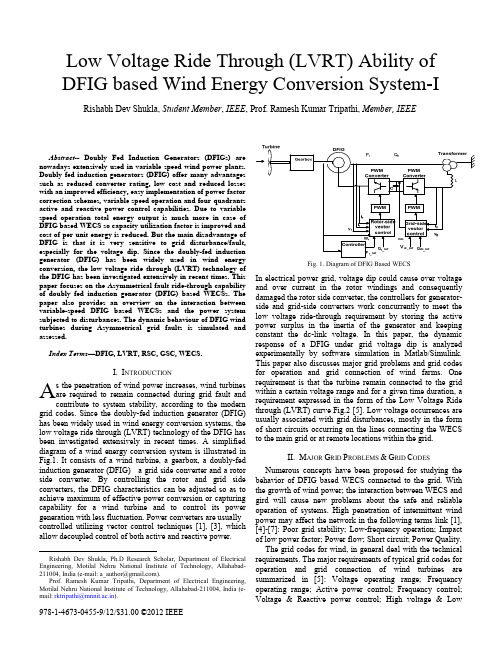
Abstract-- Doubly Fed Induction Generators (DFIGs) are nowadays extensively used in variable speed wind power plants.Doubly fed induction generators (DFIG) offer many advantages such as reduced converter rating, low cost and reduced losses with an improved efficiency, easy implementation of power factor correction schemes, variable speed operation and four quadrants active and reactive power control capabilities. Due to variable speed operation total energy output is much more in case of DFIG based WECS so capacity utilization factor is improved and cost of per unit energy is reduced. But the main disadvantage of DFIG is that it is very sensitive to grid disturbance/fault, especially for the voltage dip. Since the doubly-fed induction generator (DFIG) has been widely used in wind energy conversion, the low voltage ride through (LVRT) technology of the DFIG has been investigated extensively in recent times. This paper focuses on the Asymmetrical fault ride-through capability of doubly fed induction generator (DFIG) based WECSs. The paper also provides an overview on the interaction between variable-speed DFIG based WECSs and the power system subjected to disturbances. The dynamic behaviour of DFIG wind turbines during Asymmetrical grid faults is simulated and assessed.Index Terms—DFIG, LVRT, RSC, GSC, WECS.I. I NTRODUCTIONs the penetration of wind power increases, wind turbines are required to remain connected during grid fault and contribute to system stability, according to the modern grid codes. Since the doubly-fed induction generator (DFIG) has been widely used in wind energy conversion systems, the low voltage ride through (LVRT) technology of the DFIG has been investigated extensively in recent times. A simplified diagram of a wind energy conversion system is illustrated in Fig.1. It consists of a wind turbine, a gearbox, a doubly-fed induction generator (DFIG) a grid side converter and a rotor side converter. By controlling the rotor and grid side converters, the DFIG characteristics can be adjusted so as to achieve maximum of effective power conversion or capturing capability for a wind turbine and to control its power generation with less fluctuation. Power converters are usually controlled utilizing vector control techniques [1], [3], which allow decoupled control of both active and reactive power.Rishabh Dev Shukla, Ph.D Research Scholar, Department of Electrical Engineering, Motilal Nehru National Institute of Technology, Allahabad-211004, India (e-mail: a_author@).Prof. Ramesh Kumar Tripathi, Department of Electrical Engineering, Motilal Nehru National Institute of Technology, Allahabad-211004, India (e-mail: rktripathi@mnnit.ac.in).Fig. 1. Diagram of DFIG Based WECSIn electrical power grid, voltage dip could cause over voltage and over current in the rotor windings and consequently damaged the rotor side converter, the controllers for generator-side and grid-side converters work concurrently to meet the low voltage ride-through requirement by storing the active power surplus in the inertia of the generator and keeping constant the dc-link voltage. In this paper, the dynamic response of a DFIG under grid voltage dip is analyzed experimentally by software simulation in Matlab/Simulink. This paper also discusses major grid problems and grid codes for operation and grid connection of wind farms. One requirement is that the turbine remain connected to the grid within a certain voltage range and for a given time duration, a requirement expressed in the form of the Low Voltage Ride through (LVRT) curve Fig.2 [5]. Low voltage occurrences are usually associated with grid disturbances, mostly in the form of short circuits occurring on the lines connecting the WECS to the main grid or at remote locations within the grid.II. M AJOR G RID P ROBLEMS &G RID C ODES Numerous concepts have been proposed for studying the behavior of DFIG based WECS connected to the grid. With the growth of wind power; the interaction between WECS and gird will cause new problems about the safe and reliable operation of systems. High penetration of intermittent wind power may affect the network in the following terms link [1], [4]-[7]: Poor grid stability; Low-frequency operation; Impact of low power factor; Power flow; Short circuit; Power Quality.The grid codes for wind, in general deal with the technical requirements. The major requirements of typical grid codes for operation and grid connection of wind turbines are summarized in [5]: Voltage operating range; Frequency operating range; Active power control; Frequency control; Voltage & Reactive power control; High voltage & LowLow Voltage Ride Through (LVRT) Ability of DFIG based Wind Energy Conversion System-I Rishabh Dev Shukla, Student Member, IEEE, Prof. Ramesh Kumar Tripathi, Member, IEEEA978-1-4673-0455-9/12/$31.00 ©2012 IEEEvoltage ride through (HVRT & LVRT); Power quality; Wind farm modelling and verification; Communications & external control.Low voltage ride through (LVRT):In the event of voltage sag, the wind turbines are required to remain connected for a specific amount of time before being allowed to disconnect. In addition, some utilities require that the wind turbines help support grid voltage during faults. Period of fault or low voltage ride through depends on the magnitude of voltage drop at the Point of Common Coupling (PCC) during the fault and time taken by the grid system to recover to the normal state. Table I shows the fault clearing times for different nominal system voltages.The typicalTABLE.I[5]Nominalsystemvoltage(kV)Faultclearingtime,T(ms)Vpf(kV)Vf(kV)400 100 360 60.0220 160 200 33.0132 160 120 19.8110 160 96.25 16.566 300 60 9.9III.DFIG M ODELING &C ONTROLIn DFIG based variable-speed WECSs, the power electronicconverter only has to handle a fraction (20–30%) of the totalpower [3], [12]-[13]. This means that the losses in the powerelectronic converter can be reduced compared to a systemwhere the converter has to handle the total power. In addition,the cost of the converter becomes lower. The stator circuit ofthe DFIG is connected to the grid while the rotor circuit isconnected to a converter via slip rings, see Fig.3.Fig. 3. Operating principle of DFIG based Wind TurbineMathematical model of DFIGThe equivalent circuit of a DFIG in an arbitrary referenceframe rotating at synchronous angular speed ω shown inFig.4.[9]-[11]Fig. 4. Equivalent circuit diagram of DFIGThe stator and rotor voltages V S and V in the synchronousreference frame can be expressed as,V S R S I S λSjωSλS (1)V R I λj ωS ω λ (2)Where, flux linkagesλS L I S L I S I (3)λ L I L I I (4)Control of Rotor Side Converter (RSC)The active and reactive powers which are delivered from theDFIG to the grid are controlled by means of controlling therotor currents of the DFIG [15]-[20]. The two controllers inthe rotor side controller determine inverter d- and q- axisvoltages by comparing the d and q current set points to theactual d and q rotor current Fig.5.Fig.5. DFIG Rotor side controllerIn Stator Voltage Orientation (SVO), neglecting the statorresistive voltage drop, the active and reactive powers of thestator and rotor are expressed as eq. (5, 6, 7 & 8),P 1.5LL S LV I (5)Q 1.5VL S LVωL I (6)P 1.5 V I V I (7)Q 1.5 V I V I (8)From the above equations, it is clear that power fed to the gridcan be controlled by controlling the rotor current’scomponents. The rotor current components can be controlledby the vector control technique.Control of grid side converter (GSC)The purpose of the grid-side converter is to keep the DC linkvoltage constant irrespective of the direction of the rotorpower flow. In order to maintain the DC link voltage constant,a bidirectional converter is required to implement in the rotor side circuit. Below the synchronous speed this converter work as a rectifier and above synchronous speed this converter works as an inverter to supply all generated power to the grid at a constant DC link voltage.Fig. 6. DFIG Grid side controllerThe grid side converter typically regulates DC voltage and reactive power. It is also a two stage controller operating in a grid AC voltage reference frame. The two controllers in the grid side controller determine inverter d-and q-axis voltages by comparing the d and q-current set points to the actual d and q- currents to the grid [18].IV.S IMULATION &R ESULTSFor the purpose of studying the dynamic performance of DFIG wind turbine under normal and faulty condition with the SVO vector control scheme extensive simulation using MATLAB/SIMULINK have been performed. Theturbine has the following specifications:T ABLE IIS PECIFICATION D ATATurbine data: DFIG data:Turbine Power = 9MWRated power = 5MWMaximum outputpower = 10 MW Cut-in wind speed = 4m/sRated wind speed = 12m/sCut out wind speed =18 m/sType = 3 bladed, Upwind/Horizontal axis Rotor diameter = 82 mRotational speed at rated power = 15.6-18.4rpmSwept area = 22.89 m2Tower height =27 mWind energy utilization ratio (C p) =0.48Rated power = 9MWVoltage (line toline) = 575 VNo. of Poles = 6Frequency (f) = 60HzStator resistance(R s)= 0.00706 puRotor resistance(R r) =0.005 puStator leakageinductance (L s) = 0.171puRotor leakageinductance (L r) =0.156puMagnetizinginductance (L m) = 2.9puSimulation Configuration of the DFIG Based Wind Turbineunder Three-Phase Grid Fault:Fig. 7. Simulation configuration of DFIG under Three Phase FaultUsing the MATLAB/SIMULINK the above model is used tosimulate under the three phase short circuit current in voltagedip situation. When three phase fault occurs at 25KV Bus, thevoltage sag at 575V will depend on the percentage impedancedrop of DFIG. Using the MATLAB/SIMULINK the abovemodel is used to simulate under the three phase short circuitcurrent in voltage dip situation. When three phase fault occursat 25KV Bus, the voltage sag at 575V will depend on thepercentage impedance drop of DFIGSimulation ResultsCase 1. DFIG during Grid fault (Voltage dips to 20%)Voltage at Bus 575 V ~ TimeFig.8. Voltage at Bus 575V under 20% voltage dipCurrent at Bus 575 V ~ TimeFig. 9. Current at Bus 575 V under 20 % voltage dipRotor Speed ~ TimeFig. 10. Rotor Speed under 20 % Voltage dipTotal Active Power ~ TimeFig. 11. Total Active Power under 20% voltage dipReactive Power ~ TimeFig. 12. Reactive Power under 20 % Voltage dip4.4.3. k. Rotor Active Power ~ TimeFig. 13. Rotor Active Power under 20% voltage dipDC link Voltage ~ TimeFig. 14. DC link Voltage under 20 % Voltage dipIn this situation the active and reactive power fluctuates slightly. Unity power factor is not maintained but it does not result in a cause of great damage. Hence the decrease in value of power factor is of no great consequence. Since the DC link voltage also varies slightly, there is no risk of the link capacitor getting damaged. Case2. Wind Turbine DFIG during Grid fault (Voltage dips to 40%)Voltage at Bus 575 V ~ TimeFig. 15. Voltage at Bus 575V under 40% voltage dipCurrent at Bus 575 V ~ TimeFig. 16. Current at Bus 575 V under 40 % voltage dipThe duration of voltage sag in this simulation is 120ms. Rotor Speed ~ TimeFig. 17. Rotor Speed under 40 % Voltage dipTotal Active Power ~ TimeFig. 18. Total Active Power under 40% voltage dipReactive Power ~ TimeFig.19. Reactive Power under 40 % Voltage dipRotor Active Power ~ Time Fig. 20. Rotor Active Power under 40% voltage dipDC link Voltage ~ TimeFig. 21. DC link Voltage under 40 % Voltage dip For the duration of fault, active and reactive powers start fluctuating as rotor speeds up and down. Similarly, the DC link voltage fluctuates throughout sag. In this case the majority power flows through the rotor. This phenomenon might lead to the damage of the converters. Hence rotor protection is of paramount importance in case of majority fault condition. Since the DC link voltage varies in this case, there is considerable chance of damage to the capacitor.Case 3. Wind Turbine DFIG during Grid fault (Voltage dips to 90%)Voltage at Bus 575 V ~ TimeFig. 22. Voltage at Bus 575 V under 90 % Voltage dipRotor Speed ~ TimeFig. 23. Rotor Speed under 90% Voltage dipTotal Active Power ~ TimeFig. 24. Total Active Power under 90% voltage dip Reactive Power ~ TimeFig.25. Reactive Power under 90% Voltage dip Rotor Active Power ~ TimeFig. 26. Rotor Active Power under 90% voltage dipDC link Voltage ~ TimeFig. 27. DC link Voltage under 90% Voltage dipIn case of a 90% dip in voltage, a spiky swell in the fluctuation range is observed. The voltage starts to pull through very sluggishly. For the duration of fault, active and reactive powers continue to swing as rotor speed varies. Correspondingly, the DC link voltage fluctuates all the way through. In this case the majority power flows through the rotor. This phenomenon might lead to the damage of theconverters.V.C ONCLUSIONThis paper presents a fault ride through ability of variable speed DFIG based wind turbine when the power system is subjected to asymmetrical grid faults. The dynamic behavior of DFIG under power system disturbance is simulated by using MATLAB/SIMULINK platform using space vector control concept. Exact transient simulations are required to investigate the influence of the wind power on the power system stability. In the Stator Voltage Orientation vector control method, the magnetic saturation, electro-magnetic transients and other nonlinear factors are neglected. With the SVO based control of RSC & GSC, connected to DFIG one can control the flow of active and reactive power from DFIM to grid and maintain the DC link voltage constant under normal operating conditions at constant wind speed (12 m/s). This controller and system performances have been studied under different voltage sags. Up to 20% sag fluctuation in active power, reactive power and DC link voltage are in the tolerable range and system recovers after the fault is cleared. With 40% sag fluctuations are more as compared to previous and may become harmful for converters and capacitors but beyond this limit say at 90% sag, components like converter, capacitor etc may be permanently damaged. During fault the active and reactive powers start fluctuate in the wide range of its steady state value. After 130 ms, the fault causing the voltage sag on the 575V bus bar is cleared, as the duration of the fault is 120ms, then the wind turbine is operated under the normal condition and produces the nominal power. Using the SVO, the reactive power flow to the grid is maintained zero. This ensures the unity power factor operation of DFIG. It has been observed that under steady-state condition out of total power (4.9MW) flowing to the grid, 1.4MW is flowing through the rotor circuit (DC link) of DFIG which is about twenty eighty percent. This indicates that under normal condition the converter power rating will be around thirty percent to that of DFIG power rating.R EFERENCES[1] Bansal, R.C., Bhatti, T.S., and Kothari, D.P. (2001) ‘Some aspects of grid connected wind electric energy conversion system,Interdisciplinary Journal of Institution on Engineers (India), May, Vol. 82, pp. 25-28.[2] Nicholas W. Miller, William W. Price, and Juan J. Sanchez-Gasca, “Dynamic Modeling of GE 1.5 and 3.6 Wind Turbine-Generators,” GE Power Systems, October 27, 2003.[3] S. Müler, M. Deike, and R. W. De Doncker, “Doubly fed induction generator systems for wind turbines: A viable alternative to adjust speed over a wide range at minimal cost,” IEEE Ind. Applicat.Magazine, pp. 26–33, May/June 2002 (/ias).[4] Saad-Saund, Z., Lisboa, M.L., Ekanayka, J.B., Jenkins, N. and Strbac, G. (1998) ‘Application of Statcoms to Wind farms’, IEE proceedings Generation, Transmission and Distribution, Sept. Vol. 145, No. 5, pp. 511-516.[5] Indian Wind Grid Code-Version 1.0, July 2009.[6] World Wind Energy Report 2009 : world wind energy Association.[7] T. Ackermann and L. S¨oder, “An overview of wind energy-status 2002,” Renew. Sustain.Energy Rev., vol. 6, no. 1–2, pp. 67–128, Feb./Apr. 2002. [8] M S Vicatos, J A. Tegopoulos, Transient State Analysis of a Doublyfed Induction Generator under Three Phase Short Circuit [J], IEEE Transactions on Energy Conversion, 1991,6(1):62-68.[9] Johan Morren. Short-Circuit Current of Wind Turbines WithDoublyFed Induction Generator [J]. IEEE Transactions on Energy Conversion, 2007,22(1):174-180.[10] Hu Jia-bing,Sun Dan,He Yi-kang. A Model and Control Method of the DFIG during Grid Voltage Dip [J]. Automation of Electrical Power System, 2006, 30(8):21-26. [11] Hu Jia-bing, Yi-kang. Control and Operation of DFIG Fault Ridethrough Ability [J]. Automation of Electrical Power System, 2008, 32 (2):49-52. [12] L. Morel, H. Godfroid, A. Mirzaian, and J. Kauffmann, “Double-fed induction machine:converter optimisation and field oriented control without position sensor,” IEE Proc. Electr. Power Appl., vol. 145, no. 4, pp. 360–368, July 1998.[13] L. Xu and C. Wei, “Torque and reactive power control of a doubly fed induction machine by position sensorless scheme,” IEEE Trans. Ind. Applicat., vol. 31, no. 3, pp. 636–642, May/June 1995.[14] Ned Mohan, Ted K. A. Brekken “Control of a Doubly Fed Induction Wind Generator Under Unbalanced Grid Voltage Conditions” IEEE Transaction Energy conversion, vol.no22. 1, march 2007 page 129-135.[15] Johan Morren, Sjoerd W. H. de Haan, “Ridethrough of Wind Turbines with Doubly-Fed Induction Generator During a Voltage Dip” IEEE transaction on energy conversion june, 2005 pages 435-441 vol. 20.[16] Muller, S. et al., “Doubly Fed Induction Generator System for Wind Turbines”, IEEE Industry Application Magazine, May/June 2002.[17] Jesus Lopez, Pablo Sanchis. “Dynamic Behavior of the Doubly Fed Induction Generator during Three-Phase Voltage Dips” [J]. IEEE Transactions on Energy Conversion, 2007, 22(3):709-717.[18] R. Pena, J.C. Clare, G.M. Asher, Doubly Fed Induction Generator using Back-to-back PWM Converters and Its Application to Variable speed Wind-energy Generation[J]. IEE Proc-Electr. Power Appl, vol.143, no.3, May 1996.[19] Nicholas W. Miller, William W. Price, and Juan J. Sanchez-Gasca, “Dynamic Modeling of GE 1.5 and 3.6 Wind Turbine-Generators,” GE Power Systems, October 27, 2003.[20] S. Müler, M. Deike, and R. W. De Doncker, “Doubly fed induction generator systems for wind turbines: A viable alternative to adjust speed over a wide range at minimal cost,” IEEE Ind. Applicat.Magazine, pp. 26–33, May/June 2002 (/ias).。
1.1文献[1]文中以发电厂给煤机变频器为例,分析低电压穿越产生的原因和危害,并结合生产现场经验,从安全性、经济性分析防范措施,提出优化DCS控制逻辑和变频器控制电源是防止变频器低电压穿越事故的最佳解决方案。
方案 1,即参照《大型汽轮发电机组一类辅机变频器高、低电压穿越技术规范》要求,提高变频器自身躲过低电压穿越能力。
经投入运行的一类辅机变频器。
方案2,即一方面变频器控制电源采用UPS供电,保证控制电源不中断;另一方面优化DCS控制策略,并结合不同系统的设备允许电动机停运时间增加延时来躲过低电压穿越情况,当电源供电恢复时,及时实现变频器自启动。
[1]周道军.变频器防低电压穿越分析[J].江苏电机工程.2015.34(2):37-40.1.2文献[2]本文主要研究了在给煤机变频器交流电源输入部分加装抗低电压扰动设备的技术方案。
提出两种解决方案:方案一,在变频器中间直流环节加装 UPS(蓄电池)。
方案二,在辅机变频器前部加装抗低电压扰动设备。
并分析了电网故障情况下辅机安全运行问题,通过仿真验证了该技术方案在系统电压跌落至 20% 且持续 10 s 的情况下不灭火、不跳闸和其出力波动≤10% 的技术指标且必须保证各种运行方式下机组都具有足够的低电压穿越能力。
[2]张东明,姚秀萍,王维庆,常喜强,王海云.含低电压穿越电源的火电厂辅机变频器的研究[J].华东电力.2013.41.(6):1345-1347.1.3文献[3]本文主要阐述了高低压变频器结构,总结了各种低电压穿越改造方案,提出并联蓄电池,并联升压电路,并联升压电路加少量蓄电池,并联升压电路加厂内保安电源,串联UPS,串联升压电路等,并分析了各种方案的优缺点。
其中并联蓄电池和串联UPS取得了很好的效果。
国家电网对变频器低电压穿越的定义是:变频器及供电对象设备外部故障或扰动引起的暂态、动态或长时间电源进线电压降低到规定的低电压穿越区内时,能够可靠供电,保障供电对象的安全运行。

专利名称:Power-system with utility fault ride-through capability发明人:Erdman, William L.,Cousineau, KevinL.,Mikhail, Amir S.申请号:EP09164192.8申请日:20050107公开号:EP2114007A1公开日:20091104专利内容由知识产权出版社提供摘要:A power system with low voltage ride-through capability. An inverter is connected to the output of a generator. The generator output is conditioned by the inverter resulting in an output voltage and current at a frequency and phase angle appropriate for transmission to a utility grid. A frequency and phase angle sensor is connected to the utility grid operative during a fault on the grid. A control system is connected to the sensor and to the inverter. The control system output is a current command signal enabling the inverter to put out a current waveform, which is of the same phase and frequency as detected by the sensor. The control system synthesizes current waveform templates for all phases based on a sensed voltage on one phase and transmits currents to all phases of the electrical system based on the synthesized current waveforms.申请人:Clipper Windpower Technology, Inc.地址:6305 Carpinteria Avenue, Suite 300 Carpinteria, CA 93013 US国籍:US代理机构:Zenz更多信息请下载全文后查看。

国外有关风电并网技术规定1 丹麦丹麦是目前世界上风电装机比例最高的国家。
截止到2004年底,丹麦电力装机总量为13600MW,电源结构如图3-1所示,其中风电装机为3113MW,占22.8%。
图3-1 丹麦电力装机构成丹麦是世界上风电技术最发达的国家,Vestas公司在风电机组制造行业居全世界第一,丹麦Riso国家实验室和EMD公司分别开发了用于风能资源分析和风电场规划设计的商业化程序WAsP和WindPro,这两个程序在世界范围内得到广泛的应用。
在制定风电场接入电力系统技术规定和导则方面,丹麦也是世界上最早的国家。
在1998年,丹麦电力研究院DEFU(Research Institute of Danish Electric Utilities)提出了风电机组接入中低压电网的技术规定(Connection of Wind Turbines to Low and Medium Voltage Networks. DEFU 111,1998),用它取代先前的技术规定DEFU 77 和DEFU 100。
该技术规定适用于接入110kV以下电网的风电机组,主要涉及到风电场并网后对电能质量和供电可靠性的影响,给出了风电机组技术参数的推荐值和电压/频率保护的设置范围,但不包括风电场可能带来的稳定性问题。
针对风电场接入输电系统的情况,Eltra输电公司于2000年颁布了新的技术要求(Specifications for Connecting Wind Farms to the Transmission Networks, Second Edition),适用于风电场接入110kV以上电压等级的电网。
在该技术规定中,输电系统运行商(TSO)提出了风电运营商必须满足的技术要求,以确保电力系统在短时间和长时间内的安全性、可靠性和电能质量。
主要条款简述如下:(1) 功率控制●要求风电场能够将输出功率控制在一定的限值之内,在任何时间超过出力限值的幅度不超过风电场最大功率的5%。
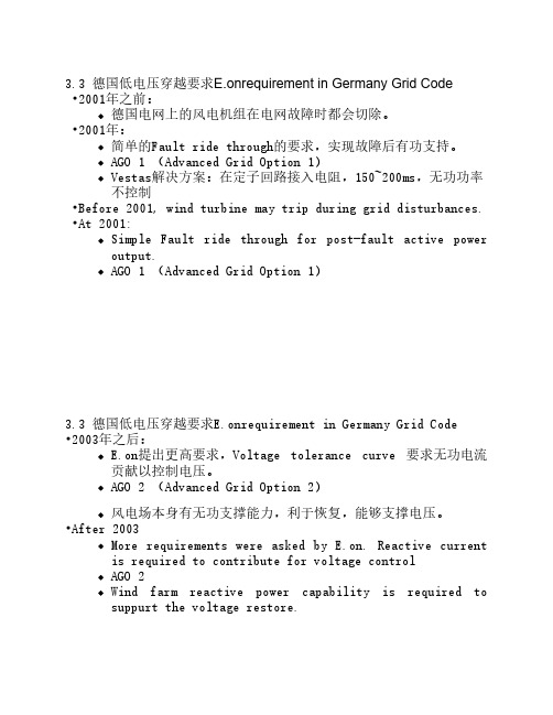
3.3 德国低电压穿越要求E.onrequirement in Germany Grid Code •2001年之前:德国电网上的风电机组在电网故障时都会切除。
•2001年:简单的Fault ride through的要求,实现故障后有功支持。
AGO 1 (Advanced Grid Option 1)Vestas解决方案:在定子回路接入电阻,150~200ms,无功功率不控制•Before 2001, wind turbine may trip during grid disturbances.•At 2001:Simple Fault ride through for post-fault active poweroutput.AGO 1 (Advanced Grid Option 1)3.3 德国低电压穿越要求E.onrequirement in Germany Grid Code •2003年之后:E.on提出更高要求,Voltage tolerance curve 要求无功电流贡献以控制电压。
AGO 2 (Advanced Grid Option 2)风电场本身有无功支撑能力,利于恢复,能够支撑电压。
•After 2003More requirements were asked by E.on. Reactive currentis required to contribute for voltage controlAGO 2Wind farm reactive power capability is required tosuppurt the voltage restore.3.3 德国低电压穿越要求E.onrequirement in Germany Grid Code德国LVRT能力规定(高短路电流)LVRT requirement for High short-circuit current 3.3 德国低电压穿越要求E.onrequirement in Germany Grid Code德国LVRT能力规定(低短路电流)LVRT requirement for low short-circuit current3.3 德国低电压穿越要求E.onrequirement in Germany Grid Code •有功输出在故障切除后立即恢复并且每秒钟至少增加额定功率的20%。