Chapter9-Bootloader
- 格式:ppt
- 大小:286.00 KB
- 文档页数:22
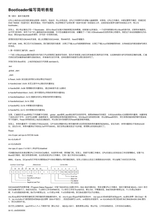
Bootloader编写简明教程第⼀部分:基本功能流程CPU上电后会从IO空间的某地址取第⼀条指令。
但此时:PLL没有启动,CPU⼯作频率为外部输⼊晶振频率,⾮常低;CPU⼯作模式、中断设置等不确定;存储空间的各个BANK(包括内存)都没有驱动,内存不能使⽤。
在这种情况下必须在第⼀条指令处做⼀些初始化⼯作,这段初始化程序与操作系统独⽴分开,称之为bootloader。
实际上,很少有必要⾃⼰写⼀个Bootloader,因为U-Boot已经强⼤到能够满⾜各种需要。
但是强⼤必然复杂,⼀个初学者想要分析U-Boot的源代码,还是有些难度的。
出于学习的⽬的,我写了这个史上最简单的启动加载器,它只包含最基本的功能,却囊括了⼀个嵌⼊式Bootloader应该有的核⼼和精华。
我把这个启动加载器命名为S-Boot,是Simple Bootloader的缩写,亦可进⼀步简称为SB。
使⽤的实验环境为OK2440开发板,板上处理器为S3C2440A,有64M内存,Nand存储器为K9F1208,64M。
⽹⼝芯⽚为CS8900A。
我们要实现的功能是:从串⼝下载Linux内核映像到RAM;从⽹⼝下载Linux内核映像到RAM;从RAM启动内核挂载NFS根⽂件系统。
1. 第⼀阶段的汇编代码:start.S⼀个嵌⼊式Bootloader最初始部分的代码⼏乎必须是⽤汇编语⾔写成的,因为开发板刚上电后没有准备好C程序运⾏环境,⽐如堆栈指针SP没有指到正确的位置。
汇编代码应该完成最原始的硬件设备初始化,并准备好C运⾏环境,这样后⾯的功能就可以⽤C语⾔来写了。
对我们的S-Boot来说,上电后的起始运⾏代码是 start/start.S。
.text.global _start_start:b Reset ; 0x00: 发⽣复位异常时从地址零处开始运⾏b HandleUndef ; 0x04: 未定义指令中⽌模式的向量地址b HandleSWI ; 0x08: 管理模式的向量地址,通过SWI指令进⼊此模式b HandlePrefetchAbort ; 0x0C: 指令预取终⽌导致的异常的向量地址b HandleDataAbort ; 0x10: 数据访问终⽌导致的异常的向量地址b HandleNotUsed ; 0x14: 保留b HandleIRQ ; 0x18: 中断模式的向量地址b HandleFIQ ; 0x1C: 快中断模式的向量地址这⾥,汇编指⽰符.text表明以下内容属于代码段,.global _start指明_start是全局可访问的符号。
嵌入式BootLoader技术内幕(一)嵌入式BootLoader技术内幕(一)本文详细地介绍了基于嵌入式系统中的 OS 启动加载程序―― Boot Loader 的概念、软件设计的主要任务以及结构框架等内容。
一、引言在专用的嵌入式板子运行GNU/Linux 系统已经变得越来越流行。
一个嵌入式Linux 系统从软件的角度看通常可以分为四个层次:1. 引导加载程序。
包括固化在固件(firmware)中的boot 代码(可选),和Boot Loader 两大部分。
2. Linux 内核。
特定于嵌入式板子的定制内核以及内核的启动参数。
3. 文件系统。
包括根文件系统和建立于Flash 内存设备之上文件系统。
通常用ram disk 来作为root fs。
4. 用户应用程序。
特定于用户的应用程序。
有时在用户应用程序和内核层之间可能还会包括一个嵌入式图形用户界面。
常用的嵌入式GUI 有:MicroWindows 和MiniGUI 懂。
引导加载程序是系统加电后运行的第一段软件代码。
回忆一下PC 的体系结构我们可以知道,PC 机中的引导加载程序由BIOS(其本质就是一段固件程序)和位于硬盘MBR 中的OS Boot Loader(比如,LILO 和GRUB 等)一起组成。
BIOS 在完成硬件检测和资源分配后,将硬盘MBR 中的Boot Loa der 读到系统的RAM 中,然后将控制权交给OS Boot Loader。
Boot Loader 的主要运行任务就是将内核映象从硬盘上读到RAM 中,然后跳转到内核的入口点去运行,也即开始启动操作系统。
而在嵌入式系统中,通常并没有像BIOS 那样的固件程序(注,有的嵌入式CPU 也会内嵌一段短小的启动程序),因此整个系统的加载启动任务就完全由Boot Loader 来完成。
比如在一个基于ARM7TD MI core 的嵌入式系统中,系统在上电或复位时通常都从地址0x00000000 处开始执行,而在这个地址处安排的通常就是系统的Boot Loader 程序。
英文回答:The official bootloader example for the Chronos RTOS presents an authoritative implementation of a bootloader for the Chronos RTOS operating system. This exemplar illustrates the process of loading and executing firmware images from a storage device, such as serial flash memory or an SD card. The example includes support for cryptographic signature verification to ensure the authenticity and integrity of firmware images prior to execution. This is a crucial security measure for embedded systems necessitating secure and reliable firmware updates. The bootloader example serves as an exemplary starting point for developing a custom bootloader for a specific embedded system, setting forth best practices in bootloader development, epassing error handling, image validation, and secure storage access.Chronos RTOS的冠方新装机提供了Chronos RTOS操作系统的新装机的权威性实施。
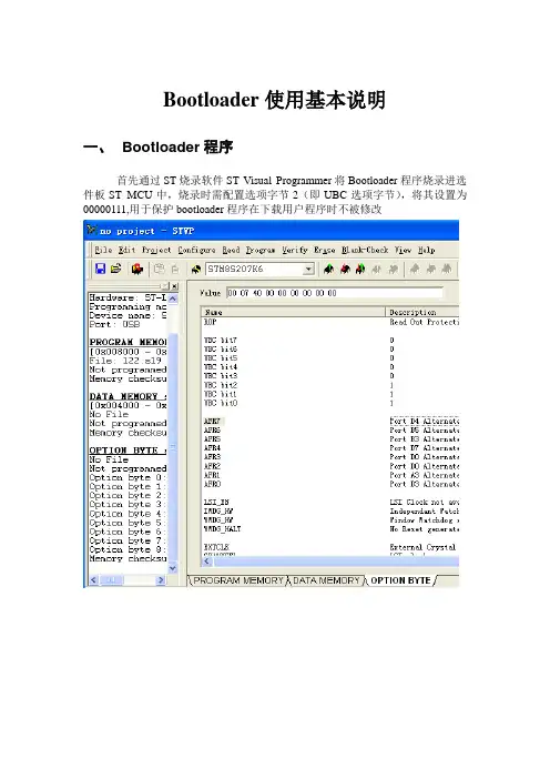
Bootloader使用基本说明一、Bootloader程序首先通过ST烧录软件ST Visual Programmer将Bootloader程序烧录进选件板ST MCU中,烧录时需配置选项字节2(即UBC选项字节),将其设置为00000111,用于保护bootloader程序在下载用户程序时不被修改二、用户程序需修改的地方1.通过ST Visual Develop仿真文件导入用户应用程序工程文件,在Project Setings中的Linker选项中Category选项框中选Input选项,然后在下面设置用户程序的中断映射地址和主程序起始地址,由于在bootloader中设置的烧录地址为0x9600,因此用户程序中断地址设为0x9600,主程序起始地址设为0x9680,重新编译生成新的.s19调试文件2.将用户程序调试所生成的的.s19文件通过ST烧录软件ST Visual Programmer导入后重新命名并另存为新的.s19文件,然后再导入bootloader烧录PC软件,如果直接导入bootloader烧录PC软件会出现0x9680段的代码和ST烧录软件所显示的0x9680段代码不符,图示如下:该图为用户程序.s19文件导入ST烧录软件所显示的用户程序代码,其中0x9680段为01 02 03 ……..该图为用户程序.s19文件直接导入bootloader烧录PC软件所显示的代码。
其中0x9680段变为36 00 00 00 00…..该图为用户程序.s19另存为后再导入bootloader烧录PC软件所显示的代码,其中0x9680段为01 02 03…与ST烧录软件显示的相同三、Bootloader烧录软件所需设置的地方1.在软件中Settings选项如下配置2.在Buffer selection中设置每一包数据的大小为128,起始地址为0x9600,结束地址为0xFFFF,输入后哦按回车键即可选中所导入的.s19文件中0x9600到0xFFFF段代码3.在配置好选项后点击Connect进行连接,连接成功则红灯变为绿灯,且设备信息栏会显示版本号和命令字符4.然后可点击WriteData,会弹出对话框要求设置程序在目标Flash中存放的起始地址,一样需设为0x9600,即可向MCU Flash区烧录程序,左下方进度条会提示程序烧录的进度5.每一次MCU上电后,只能进行一次Connect,如需再连接需给MCU重新上电6.如果在MCU Flash0x9600段本身存有用户程序时,则需在MCU上电后规定时间内立即点击Connect进行通信,否则bootloader程序将自动跳转到用户程序执行而使得连接不上,时间大概为1-2秒之内。
一、BootLoader是怎么下载应用程序的?应用程序的写入可通过S19文件。
S19文件为飞思卡尔推荐使用的标准文件传送格式,是一段直接烧写进芯片的ASCII码格式:记录类型、记录长度、存储地址、代码数据和校验码5个部分组成每一行总是以S开头,后一位跟着的数据表示改行记录的类型。
S0:说明性信息,非程序数据S1:程序数据,且地址为16位S2: 程序数据,且地址为24位S9:整个S19文件的结束行浅谈BootLoader中的Flash与RAM划分:二、为什么要划分出一块RAM区?对P-Flash擦除与写入操作的时候,不允许同时对其进行读取,故此,对Flash的擦除、写入以及CAN终端信号的处理代码,应复制到RAM中运行。
怎么做?(在飞思卡尔XET256中,这一功能可通过关键字RELOCATE_TO实现。
)因此在划分Flash的同时也应对RAM进行划分,以实现这一功能。
(定义RAM的关键字为READ_WRITE)这样做后得到什么样的结果?划分出一个与P-Flash大小相等的一块RAM区三、关于BootLoader中的地址分配问题飞思卡尔16位单片机复位后总是从优先级最高的中断向量地址0xFFFE处取第一条执行指令。
因此,BootLoader 可执行代码的首地址应安排在此处,以保证上电后BootLoader最先执行。
这可以通过在prm文件中定义VECTOT 0 实现,即将VECTOR 0 定义为Bootloader程序的入口地址。
而应用程序也同样希望对VECTOR 0 定义,以实现在单片机上电后直接执行应用程序的目的。
由于存在这一中断资源冲突,因此,BootLoader在刷写时需要对应用程序的中断向量表进行重新分配。
四、通信协议BootLoader的通信协议的目的是什么?实现BootLoader于上位机之间的命令和状态传输怎么做?在标准的CAN协议基础上,定义一套简单的通信协议。
该协议中所使用的命令和状态均以报文ID表示,即每一个ID代表一个特定的命令或状态。
Bootloader Awareness Manual corebootRelease 09.2023TRACE32 Online HelpTRACE32 DirectoryTRACE32 IndexTRACE32 Documents ......................................................................................................................Bootloader Awareness Manuals ..................................................................................................Bootloader Awareness Manual coreboot (1)History (3)Overview (4)Brief Overview of Documents for New Users4Supported Versions (5)Configuration (6)x86 32-Bit6 x64 64-Bit6Features (7)Display of coreboot Resources7 Coreboot Specific Menu8Coreboot Commands (9) Display coreboot build information9 EXTension.BuildCONF Display coreboot build configuration9 EXTension.LOG Display coreboot log10 EXTension.CBFS Display coreboot file system11 EXTension.TimeStamps Display timestamps12 EXTension.MemoryMAP Display memory mapping13 EXTension.CBTABLE Display contents of coreboot tables14Version 09-Oct-2023 History28-Aug-18The title of the manual was changed from “Bootloader Debugger for <x>” to “Bootloader Awareness Manual <x>”.OverviewThe Bootloader Awareness for coreboot contains special extensions to the TRACE32 Debugger. This chapter describes the additional features, such as additional commands and debugging approaches. Brief Overview of Documents for New UsersArchitecture-independent information:•“Training Basic Debugging” (training_debugger.pdf): Get familiar with the basic features of a TRACE32 debugger.•“T32Start” (app_t32start.pdf): T32Start assists you in starting TRACE32 PowerView instances for different configurations of the debugger. T32Start is only available for Windows.•“General Commands” (general_ref_<x>.pdf): Alphabetic list of debug commands.Architecture-specific information:•“Processor Architecture Manuals”: These manuals describe commands that are specific for the processor architecture supported by your Debug Cable. T o access the manual for your processorarchitecture, proceed as follows:-Choose Help menu > Processor Architecture Manual.•“OS Awareness Manuals” (rtos_<os>.pdf): TRACE32 PowerView can be extended for operating system-aware debugging. The appropriate OS Awareness manual informs you how to enable theOS-aware debugging.•“UEFI Awareness Manuals” (uefi_<x>.pdf): TRACE32 PowerView can be extended for UEFI-aware debugging. The appropriate UEFI manual informs you how to enable the UEFI-awaredebugging.Supported VersionsCurrently coreboot is supported for the following versions:•coreboot on x86 and x64 architecturesConfigurationThe Bootloader Awareness for coreboot is configured by loading an extension definition file called“coreboot.t32” from the demo directory with the EXTension.CONFIG command. Additionally, load the “coreboot.men” menu file (see “Coreboot specific Menu”).x86 32-BitA full configuration for x86 32-bit can look like this (the path prefix ~~ expands to the system directory ofTRACE32):; Load the debug symbolsData.LOAD.Elf <path_to_bootblock.elf>/bootblock.elf /NoCODEData.LOAD.Elf <path_to_romstage.elf>/romstage.elf /NoCODE /NoClearData.LOAD.Elf <path_to_ramstage.elf>/ramstage.elf /NoCODE /NoClear; Load the Bootloader Awareness for coreboot:EXTension.CONFIG ~~/demo/x86/bootloader/coreboot/coreboot.t32; Load the additional menu:MENU.ReProgram ~~/demo/x86/bootloader/coreboot/coreboot.menx64 64-BitA full configuration for x64 64-bit can look like this (the path prefix ~~ expands to the system directory ofTRACE32):; Load the debug symbolsData.LOAD.Elf <path_to_bootblock.elf>/bootblock.elf /NoCODEData.LOAD.Elf <path_to_romstage.elf>/romstage.elf /NoCODE /NoClearData.LOAD.Elf <path_to_ramstage.elf>/ramstage.elf /NoCODE /NoClear; Load the Bootloader Awareness for coreboot:EXTension.CONFIG ~~/demo/x64/bootloader/coreboot/coreboot.t32; Load the additional menu:MENU.ReProgram ~~/demo/x64/bootloader/coreboot/coreboot.menFeaturesThe Bootloader Awareness supports the following features.Display of coreboot ResourcesThe extension defines new commands to display various resources. Information on the following coreboot components can be displayed: Build informationEXTension.LOG Log bufferEXTension.CBFS CBFS “coreboot file system”EXTension.BuildCONF Coreboot build configurationEXTension.TimeStamp TimestampsEXTension.MemoryMAP Memory mappingEXTension.CBTABLE <address>Coreboot tables contentFor a detailed description of each command, refer to chapter “Coreboot Commands”.Since the x86/x64/Atom architecture does not allow to read memory while the program execution is running, the information can only be displayed if the program execution is stopped.Coreboot Specific MenuThe menu file “coreboot.men” contains a menu with coreboot specific menu items. Load this menu with the MENU.ReProgram command.Y ou will find a new menu called Coreboot.•The Display menu items launch the coreboot resource display windows.•Selecting Coreboot Tables will open the following dialog.The coreboot tables are created at the end of “ramstage”. The object of this dialog is to runcoreboot until the coreboot tables are created and its address is set.•Selecting Detect Payload will open the following dialog.The payload name is extracted from the configuration file within the CBFS. If the payload name isnot listed in the configuration file, the dialog will show an empty string.Coreboot CommandsDisplay coreboot build informationDisplays the coreboot build information (coreboot version, coreboot build date, mainboard identification).EXTension.BuildCONFDisplay coreboot build configurationDisplays the build configuration.The configuration is extracted from the CBFS. Per default, coreboot adds the configuration file (.config) within the CBFS.Format:Format:EXTension.BuildCONFEXTension.LOG Display coreboot log Format:EXTension.LOGThe log is saved on memory in a buffer. The EXTension.LOG window shows the buffer size, the buffer cursor and log level.“magic” is a unique ID, used by the Bootloader Awareness to identify the buffer address. The “magic” field ismouse sensitive. Right-clicking on it will show a local menu.The “log level” field is mouse sensitive. Right-clicking on it will show the following dialog.EXTension.CBFSDisplay coreboot file systemDisplays the CBFS with details (File name, type, size, and specific characteristics).“magic” is a unique ID, used by the Bootloader Awareness to identify the address of each “file” in memory .The “magic” fields are mouse sensitive. Right-clicking on them will show a local menu.Format:EXTension.CBFSEXTension.TimeStampsDisplay timestampsDisplays all events saved by coreboot and the duration of each event.The “magic” fields are mouse sensitive. Right-clicking on them will show a local menu.Clicking the Config button will display the timestamp configuration.Format:EXTension.TimeStampsEXTension.MemoryMAPDisplay memory mapping Displays the memory mapping: start and end address and identification of each memory region.The “magic” fields are mouse sensitive. Right-clicking on them will show a local menu.A RAM dump of a specific region can be saved by selectinggenerate RAM dump from the local menu of the “magic” field. The binary name and memory range addresses will be set automatically .Format:EXTension.MemoryMAPEXTension.CBTABLEDisplay contents of coreboot tables Displays the contents of coreboot tables. Format:EXTension.CBTABLE<address><address>Coreboot table address。
bootloader启动过程详细说明今天早上看了⼀上午的bootloader简单源码,终于捋顺了bootloader的执⾏过程,之前只是知道bootloader代码会先被irom中的代码拷贝到iram中⼀部分,然后执⾏这部分代码,会把整个bootloader代码拷贝到sdram中,最终在sdram执⾏剩下的代码,⽽这段代码会把kernel拷贝到sdram的某个地址,最终引导起来整个内核。
但是我今天早上看代码的时候看到⼀个问题,我所有的代码都是⾃⼰动⼿实现的,只要⼀步⼀步按照顺序来,不就可以实现么?为什么还要拷贝来拷贝去的。
感觉直接按照跳转的⽅式,跳转值进⾏指令的跳转就⾏,但是想过之后,我意识到⾃⼰真是⽆知了。
⽐如说在irom中执⾏的时候,会有⼀次跳转到iram中某⼀个地址,当然pc是肯定可以直接跳转到指定的任何⼀个地址,但是在这个地址中没有存放指令码,这时候,肯定是⼀个有去⽆回的过程,不仅这样,这个pc跳到这⾥后,就会很迷茫,前不着村,后不着店的,不知道⾃⼰的所去所从,就会死到这⾥。
只有先把代码拷贝到将要跳转的地址中,pc指针才会顺着跳转后的指令继续执⾏,也就是说每⼀个指令都要负责⼈,确保执⾏完这个指令后,⼀定要有另⼀个指令去接纳pc。
这样pc才会⼀直活在我的代码中。
下边我就再把我更进⼀步了解到的bootloader执⾏过程再重新叙述⼀下:我使⽤的是s5pv210芯⽚、K9K8G08U0A型号的nand flash第⼀步:cpu启动起来后,先来到0x00000000这个地址处(也就是irom的地址),此时会看到有⼀段代码(这是irom中固定的代码)在这⾥,这段代码会找到bootloader的第⼀段代码(以下就称为BL1)存放的地址,由于BL1存放在nand flash中,不⽀持⽚上执⾏,所以irom会把这段代码拷贝到iram中,但是在拷贝之前,irom会先把iram的起始4个地址分别写上⼀定的内容(不过通常只写0x00地址为BL1所占空间的⼤⼩(⼀般是8k),⽽其他三个地址全写为0),把BL1这段代码拷贝到iram后,irom的使命就快要完成了,irom的最后⼀个任务就是把pc指针指向放BL1的那块地址的起始位置,然后就按照这个地址的指令开始执⾏。