DS75176B
- 格式:pdf
- 大小:286.24 KB
- 文档页数:8

TPS系统I/O卡件介绍发布时间:2009-10-14 作者:樊庆欣Honeywell TPS系统UCN网的PMM成为目前众多企业采用的首选过程管理器,负责PMM与现场信息采集作用的I/O处理器是此系统至关重要的组成部分,它的好坏直接影响控制室对现场信息的了解,以及根据信息对现场设备所进行的调节和控制,因此直接关系到企业生产的安全性和可靠性。
I/O卡件的功能:I/O卡件与现场终端端子相连,对所有现场输入/输出信号进行处理模拟输入:将来自现场变送器、检测元件的信号转换成工程单位信号,完成监视或供其它I/O 单元进行运算控制。
模拟输出:对输出参数提供独立的D/A转换,用于控制现场的调节阀或其它执行机构。
数字输入:将来自现场的数字输入信号经转换,以指示现场过程设备的状态或供其它PM数据点使用。
数字输出:向现场提供数字式输出的驱动切断阀门、机泵等现场设备。
I/O卡件的种类:根据卡件所处理信号的不同,可以分为:AO、DO、DI、HLAI、LLAI、LLMUX、STI、SDI 等多种。
I/O卡件主要硬件组成:A、处理器:采用80C31和80C32处理器。
B、程序存储器:采用27C512—64K存储单元、27C256—32K存储单元C、数据存储器:采用HM62256-10T 32K存储量D、时钟发生器:外接12KHZ晶振,由CPU内部振荡器产生工作时钟。
E、脉冲宽度调节器及电压调节器:SG2524/SG1524产生基准电压和振荡频率,实现DC -DC转换,以提供I/O板卡稳定工作所需的电压。
F、数据输入/输出器件:串行接口:DS75176/3695等;由触发/驱动器件组成的并行输入扩展SCC2697(LLMUX)、HC374(DI)、HC244(HLAI); 并行输出扩展HC374(AO-8)、HC273(DO)等其它标准接口器件.G、外围控制器件:完成逻辑关系运算、控制功能。
I/O卡件的总线:A、数据总线:8位并行数据总线对应CPU的P0.0-P0.7和一对串行收发线RXD/TXD.B、地址总线:ROM地址线为15位,低8位对应CPU的P0.0-P0.7口、高7位对应P2.0-P2.6,剩余一条P2.7作为控制选通端和PSEN、RD一起对ROM的OE端选通。


RVN4126 3.59100-386-9100-386/T DEVICERVN41772-CD2-3.5MCS/MTSRVN41821-CD2-3.5XTS3000/SABER PORTABLE YES RKN4046KHVN9085 3.51-20 R NO HLN9359 PROG. STAND RVN4057 3.532 X 8 CODEPLUG NO3080385B23 & 5880385B30 MDVN4965 3.59100-WS/T CONFIG KITRVN4053 3.5ASTRO DIGITAL INTERFACE NO3080385B23RVN41842-CD RKN4046A (Portable) 2-3.5ASTRO PORTABLE /MOBILE YES3080369B73 or0180300B10 (Mobile) RVN41831-CD3080369B732-3.5ASTRO SPECTRA MOBILE YES(Low / Mid Power)0180300B10 (High Power) RVN4185CD ASTRO SPECTRA PLUS MOBILE NO MANY OPTIONS; SEESERVICE BRIEF#SB-MO-0101RVN4186CD ASTRO SPECTRA PLUS MANY OPTIONS;MOBILE/PORTABLE COMB SEE SERVICE BRIEF#SB-MO-0101RVN4154 3.5ASTROTAC 3000 COMPAR.3080385B23RVN5003 3.5ASTROTAC COMPARATORS NO3080399E31 Adpt.5880385B34RVN4083 3.5BSC II NO FKN5836ARVN4171 3.5C200RVN4029 3.5CENTRACOM SERIES II NO VARIOUS-SEE MANUAL6881121E49RVN4112 3.5COMMAND PLUS NORVN4149 3.5COMTEGRA YES3082056X02HVN6053CD CT250, 450, 450LS YES AAPMKN4004RVN4079 3.5DESKTRAC CONVENTIONAL YES3080070N01RVN4093 3.5DESKTRAC TRUNKED YES3080070N01RVN4091 3.5DGT 9000 DESKSET YES0180358A22RVN4114 3.5GLOBAL POSITIONING SYS.NO RKN4021AHVN8177 3.5GM/GR300/GR500/GR400M10/M120/130YES3080070N01RVN4159 3.5GP60 SERIES YES PMLN4074AHVN9128 3.5GP300 & GP350RVN4152 3.5GP350 AVSRVN4150 3.5GTX YES HKN9857 (Portable)3080070N01(Mobile) HVN9025CD HT CDM/MTX/EX SERIES YES AARKN4083/AARKN4081RiblessAARKN4075RIBLESS NON-USA RKN4074RVN4098H 3.5HT1000/JT1000-VISAR YES3080371E46(VISAR CONV)RVN4151 3.5HT1000 AVSRVN4098 3.5HT1000/ VISAR CONV’L.YES RKN4035B (HT1000) HVN9084 3.5i750YES HLN-9102ARVN4156 3.5LCS/LTS 2000YES HKN9857(Portable)3080070N01(Mobile) RVN4087 3.5LORAN C LOC. RECV’R.NO RKN4021ARVN4135 3.5M100/M200,M110,M400,R100 includesHVN9173,9177,9646,9774YES3080070N01RVN4023 3.5MARATRAC YES3080070N01RVN4019 3.5MAXTRAC CONVENTIONAL YES3080070N01RVN4139 3.5MAXTRAC LS YES3080070N01RVN4043 3.5MAXTRAC TRK DUPLEX YES3080070N01RVN4178CD MC SERIES, MC2000/2500DDN6124AW/DB25 CONNECTORDDN6367AW/DB9 CONNECTOR RVN41751-CD Rib to MIC connector 1-3.5MCS2000 RKN4062BRVN41131-3.5MCS2000RVN4011 3.5MCX1000YES3000056M01RVN4063 3.5MCX1000 MARINE YES3000056M01RVN4117 3.5MDC/RDLAP DEVICESRVN4105 3.5MOBILE PROG. TOOLRVN4119 3.5MOBITEX DEVICESRVN4128 3.5MPT1327-1200 SERIES YES SEE MANUALRVN4025 3.5MSF5000/PURC/ANALOG YES0180355A30RVN4077 3.5MSF5000/10000FLD YES0180355A30RVN4017K 3.5MT 1000YES RTK4205CRVN4148 3.5MTR 2000YES3082056X02RVN4140 3.5MTRI 2000NORVN41761-CD MTS2000, MT2000*, MTX8000, MTX90001-3.5*programmed by DOS which is included in the RVN4176RVN4131 3.5MTVA CODE PLUG FIXRVN4142 3.5MTVA DOCTOR YES3080070N01RVN4131 3.5MTVA3.EXERVN4013 3.5MTX800 & MTX800S YES RTK4205CRVN4097 1-CD MTX8000/MTX9000,MTS2000,MT2000*,* programmed by DOS which is included in the RVN4176HVN9067CD MTX850/MTX8250MTX950,MTX925RVN4138 3.5MTX-LS YES RKN4035DRVN4035 3.5MX 1000YES RTK4203CRVN4073 3.5MX 800YES RKN4006BHVN9395 P100, P200 LB, P50+, P210, P500, PR3000RVN4134 3.5P100 (HVN9175)P200 LB (HVN9794)P50+ (HVN9395)P210 (HVN9763)P500 (HVN9941)PR3000 (HVN9586)YES RTK4205HVN9852 3.5P110YES HKN9755A/REX1143 HVN9262 3.5P200 UHF/VHF YES RTK4205RVN4129 3.5PDT220YVN4051 3.5PORTABLE REPEATER Portable rptr.P1820/P1821AXRVN4061C 3.5PP 1000/500NO3080385B23 & 5880385B30 RVN5002 3.5QUANTAR/QUANTRO NO3O80369E31RVN4135 3.5R100 (HVN9177)M100/M200/M110/M400YES0180358A52RVN4146 3.5RPM500/660RVN4002 3.5SABER YES RTK4203CRVN4131 3.5SETTLET.EXEHVN9007 3.5SM50 & SM120YESRVN4039 3.5SMART STATUS YES FKN5825AHVN9054 3.5SOFTWARE R03.2 P1225YES3080070N01HVN9001 3.5SOFTWARE R05.00.00 1225LS YES HLN9359AHVN9012 3.5SP50RVN4001N 3.5SPECTRA YES3080369B73 (STANDARD)0180300B10 (HIGH POWER) RVN4099 3.5SPECTRA RAILROAD YES3080369B73RVN4110 3.5STATION ACCESS MODULE NO3080369E31RVN4089A 3.5STX TRANSIT YES0180357A54RVN4051 3.5SYSTEMS SABER YES RTK4203BRVN4075 3.5T5600/T5620 SERIES NO3080385B23HVN9060CD TC3000, TS3000, TR3000RVN4123 3.5VISAR PRIVACY PLUS YES3080371E46FVN4333 3.5VRM 100 TOOLBOX FKN4486A CABLE &ADAPTORRVN4133 3.5VRM 500/600/650/850NORVN4181CD XTS 2500/5000 PORTABLES RKN4105A/RKN4106A RVN41002- 3.5XTS3000 ASTRO PORTABLE/MOBILERVN4170 3.5XTS3500YES RKN4035DRIB SET UPRLN4008E RADIO INTERFACE BOX (RIB)0180357A57RIB AC POWER PACK 120V0180358A56RIB AC POWER PACK 220V3080369B71IBM TO RIB CABLE (25 PIN) (USE WITH XT & PS2)3080369B72IBM TO RIB CABLE (9 PIN)RLN443825 PIN (F) TO 9 PIN (M) ADAPTOR (USE W/3080369B72 FOR AT APPLICATION) 5880385B308 PIN MODULAR TO 25 PIN ”D” ADAPTOR (FOR T5600 ONLY)0180359A29DUPLEX ADAPTOR (MOSTAR/TRAXAR TRNK’D ONLY)Item Disk Radio RIB Cable Number Size Product Required Number Item Disk Radio RIB Cable Number Size Product Required NumberUtilizing your personal computer, Radio Service Software (RSS)/Customer Programming Software (CPS)/CustomerConfiguration Software (CCS) enables you to add or reprogram features/parameters as your requirements change. RSS/CPS/CCS is compatible with IBM XT, AT, PS/2 models 30, 50, 60 and 80.Requires 640K RAM. DOS 3.1 or later. Consult the RSS users guide for the computer configuration and DOS requirements. (ForHT1000, MT/MTS2000, MTX838/8000/9000, Visar and some newer products —IBM model 386, 4 MEG RAM and DOS 5.0 or higher are recommended.) A Radio Interface Box (RIB) may be required as well as the appropriate cables. The RIB and cables must be ordered separately.Licensing:A license is required before a software (RVN) order is placed. The software license is site specific (customer number and ultimate destination tag). All sites/locations must purchase their own software.Be sure to place subsequent orders using the original customer number and ship-to-tag or other licensed sites; ordering software without a licensed customer number and ultimate tag may result in unnecessary delays. To obtain a no charge license agreement kit, order RPX4719. To place an order in the U.S. call 1-800-422-4210. Outside the U.S., FAX 847-576-3023.Subscription Program:The purchase of Radio ServiceSoftware/Customer Programming/Customer ConfigurationSoftware (RVN & HVN kits) entitles the buyer/subscriber to three years of free upgrades. At the end of these three years, the sub-scriber must purchase the same Radio Service Software kit to receive an additional three years of free upgrades. If the sub-scriber does not elect to purchase the same Radio Service Software kit, no upgrades will be sent. Annually a subscription status report is mailed to inform subscribers of the RSS/CPS/CCS items on our database and their expiration dates.Notes:1)A subscription service is offered on “RVN”-Radio Service Software/Customer Programming/Customer Configuration Software kits only.2)“RVN” software must only be procured through Radio Products and Services Division (RPSD). Software not procured through the RPSD will not be recorded on the subscription database; upgrades will not be mailed.3)Upgrades are mailed to the original buyer (customer number & ultimate tag).4)SP software is available through the radio product groups.The Motorola General Radio Service Software Agreement is now available on Motorola Online. If you need assistance please feel free to submit a “Contact Us” or call 800-422-4210.SMART RIB SET UPRLN1015D SMART RIB0180302E27 AC POWER PACK 120V 2580373E86 AC POWER PACK 220V3080390B49SMARTRIB CABLE (9 PIN (F) TO 9 PIN (M) (USE WITH AT)3080390B48SMARTRIB CABLE (25 PIN (F) TO 9 PIN (M) (USE WITH XT)RLN4488ASMART RIB BATTERY PACKWIRELESS DATA GROUP PRODUTS SOFTWARERVN4126 3.59100-386/9100T DEVICES MDVN4965 3.59100-WS/T CONFIG’TN RVN41173.5MDC/RDLAP DEVICESPAGING PRODUCTS MANUALS6881011B54 3.5ADVISOR6881029B90 3.5ADVISOR ELITE 6881023B20 3.5ADVISOR GOLD 6881020B35 3.5ADVISOR PRO FLX 6881032B30 3.5BR8506881032B30 3.5LS3506881032B30 3.5LS5506881032B30 3.5LS7506881033B10 3.5LS9506881035B20 3.5MINITOR III8262947A15 3.5PAGEWRITER 20008262947A15 3.5PAGEWRITER 2000X 6881028B10 3.5TALKABOUT T3406881029B35 3.5TIMEPORT P7308262947A15 3.5TIMEPORT P930NLN3548BUNIVERSAL INTERFACE KITItem Disk Radio NumberSize Product。
LG IG5 3.7KW---2.2KW 380V故障:一般LG的故障由主板引起的有无显示、电位器调不了速、通讯故障等。
在驱动板是好的情况下,主板引起故障的维修方法分析及排除如下:1.无显示故障排除方法无显示一般除底版和开关电源引起故障,主板也经常出现无显示的,办法是先找排插,万用表测量与好的主板对比参数,大多数与3个R271(电阻)的线路扩展找,有很多电阻烧坏的,比如查找R1R3R4R7R812R16R18R19R20R21R22R49等。
主板U2(IC3404)也会引起无显示的,还有震荡器和U10(31AKDS75176BM、MEACDS75176BM)及旁边的电阻损坏也是无显示或者报OC、OU、OH,由于主板一个电阻都有可能一起故障。
2.电位器调不了参数排除方法:先检查光藕PC2.PC3.PC4,如果测量它们的参数相同(不能超过正负5的误差,否则就要换新的),这样在换U9(788J),换上788J后,上电会显示0.00,这个时候,当自己设置好50.00H后,测量输出是否平衡,平衡了在带电机。
如果发现U、V、W、有一项没有输出电压,应该检查光藕PC14、PC15、PC17这三个,它们型号是(5F112A)量下他们参数是与好的主板是不是一样,如果不同就换新的光藕。
大多数换上后输出电压都会正常,有时候还要换U5(33EE7TK、37DL38KLS06、51AJ8HK、57A81RKLS06)换好后这样就会和新的机器运转一样,没有任何瑕疵和不正常的运行声音。
3. 大多主板引起通讯故障报警IOLE,检查电路板是不是有氧化或者被腐蚀的焊脚,电路短路的情况,由于U1(2901)经常会内部线路故障也会报IOLE,其一是更换新的IC,也可以拆坏板应对故障,U1(2901)旁边的电阻与CPU连接线路和CPU周围的电阻是否损坏,以上是LG经常出现的复杂故障。
LG主板大多都通用,我强调在维修时,更换光藕和IC时,看好型号,2.2KW与3.7KW 的IC及光藕有很大区别,在同型号的情况下可替换,反之就是明明换了好的器件也解决不了根本问题。
—16—收稿日期:2009-02-04机 车 电 传 动ELECTRIC DRIVE FOR LOCOMOTIVES№4, 2009July 10, 2009 2009年第4期 2009年7月10日研究开发基于VXWORKS的RS485-MVB网关的设计与实现肖家博1,2,杨卫峰2,黎福海1(1. 湖南大学电气与信息工程学院,湖南 长沙 410083;2. 株洲南车时代电气股份有限公司技术中心,湖南株洲412001)作者简介:肖家博(1980-),男,工程师,硕士研究生,主要从事列车控制系统基础平台研究与开发、嵌入式系统研究与应用。
摘要:针对目前列车网络控制系统的需要,设计了列车网络控制系统中MVB与RS485通信互连的网关。
重点介绍了基于VXWORKS操作系统、COLDFIRE处理器平台实现RS485- MVB网关的软、硬件设计方案与技术。
该网关系统充分利用了COLDFIRE处理器的片上资源及其优势,能很好地满足RS485-MVB网关系统的要求,具有较高的可靠性和较强的实用性。
关键词:VXWORKS操作系统;COLDFIRE处理器;RS485-MVB网关;MVB;RS485中图分类号:TN915.05;U266 文献标识码:A 文章编号:1000-128X(2009)04-0016-03Design and Implementation of RS485-MVB Gateway Based on VXWORKSXIAO Jiao-bo1,2, YANG Wei-feng2, LI Fu-hai1(1. College of Electrical and Information Engineering, Hunan University, Changsha, Hunan 410083, China;2. Technology Center, Zhuzhou CSR Times Electric Co., Ltd., Zhuzhou, Hunan 412001, China)Abstract:According to the current needs of train network control system, this paper designs gateway communicated between MVB and RS485. The paper puts emphasis on the scheme and technology of software and hardware of RS485-MVB gateway, which is based on VXWORKS operating system and COLDFIRE processor platform. The gateway system makes full use of the resources and advantages of the COLDFIRE processor-chip to meet the needs of the RS485-MVB gateway system and has the advantages of high reliability and applicability.Key words:VXWORKS operating system; COLDFIRE processor; RS485-MVB gateway; MVB; RS4850引言当前国际上主要的机车供应商为用户提供的列车控制系统都采用了符合IEC61375标准的TCN网络,如西门子公司的SIBAS32、BOMBARDIER公司的MITRAC等。
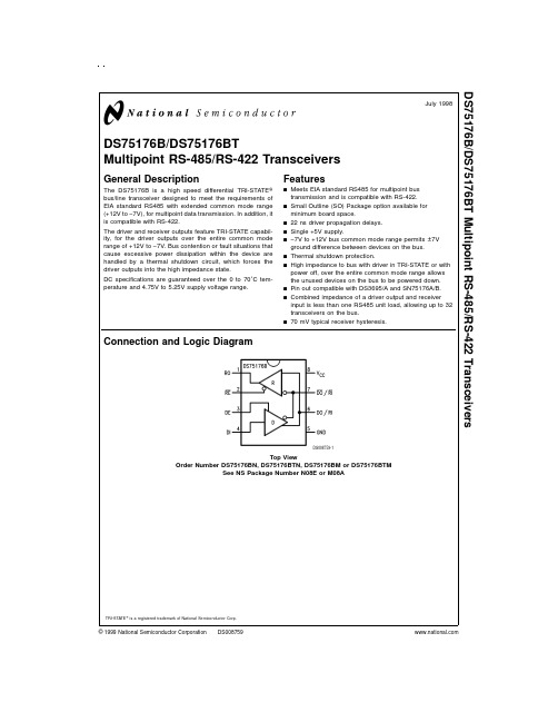
DS75176B/DS75176BTMultipoint RS-485/RS-422TransceiversGeneral DescriptionThe DS75176B is a high speed differentialTRI-STATE ®bus/line transceiver designed to meet the requirements of EIA standard RS485with extended common mode range (+12V to −7V),for multipoint data transmission.In addition,it is compatible with RS-422.The driver and receiver outputs feature TRI-STATE capabil-ity,for the driver outputs over the entire common mode range of +12V to −7V.Bus contention or fault situations that cause excessive power dissipation within the device are handled by a thermal shutdown circuit,which forces the driver outputs into the high impedance state.DC specifications are guaranteed over the 0to 70˚C tem-perature and 4.75V to 5.25V supply voltage range.Featuresn Meets EIA standard RS485for multipoint bus transmission and is compatible with RS-422.n Small Outline (SO)Package option available for minimum board space.n 22ns driver propagation delays.n Single +5V supply.n −7V to +12V bus common mode range permits ±7V ground difference between devices on the bus.n Thermal shutdown protection.n High impedance to bus with driver in TRI-STATE or with power off,over the entire common mode range allows the unused devices on the bus to be powered down.n Pin out compatible with DS3695/A and SN75176A/B.n Combined impedance of a driver output and receiver input is less than one RS485unit load,allowing up to 32transceivers on the bus.n 70mV typical receiver hysteresis.Connection and Logic DiagramTRI-STATE ®is a registered trademark of National Semiconductor Corp.DS008759-1Top ViewOrder Number DS75176BN,DS75176BTN,DS75176BM or DS75176BTMSee NS Package Number N08E or M08AJuly 1998DS75176B/DS75176BT Multipoint RS-485/RS-422Transceivers©1999National Semiconductor Corporation Absolute Maximum Ratings(Note1)If Military/Aerospace specified devices are required, please contact the National Semiconductor Sales Office/ Distributors for availability and specifications.Supply Voltage,V CC7V Control Input Voltages7V Driver Input Voltage7V Driver Output Voltages+15V/−10V Receiver Input Voltages(DS75176B)+15V/−10V Receiver Output Voltage 5.5V Continuous Power Dissipation@25˚Cfor M Package675mW(Note5) for N Package900mW(Note4) Storage Temperature Range−65˚C to+150˚C Lead Temperature(Soldering,4seconds)260˚C Recommended Operating ConditionsMin Max Units Supply Voltage,V CC 4.75 5.25V Voltage at Any Bus Terminal−7+12V (Separate or Common Mode)Operating Free Air Temperature T ADS75176B0+70˚C DS75176BT−40+85˚C Differential Input Voltage,VID(Note6)−12+12VElectrical Characteristics(Notes2,3)0˚C≤T A≤70˚C,4.75V<V CC<5.25V unless otherwise specifiedSymbol Parameter Conditions Min Typ Max Units V OD1Differential Driver Output I O=05V Voltage(Unloaded)V OD2Differential Driver Output(Figure1)R=50Ω;(RS-422)(Note7)2V Voltage(with Load)R=27Ω;(RS-485) 1.5V ∆V OD Change in Magnitude of DriverDifferential Output Voltage For0.2VComplementary Output StatesV OC Driver Common Mode Output(Figure1)R=27Ω 3.0V Voltage∆|V OC|Change in Magnitude of DriverCommon Mode Output Voltage0.2VFor Complementary OutputStatesV IH Input High Voltage2V V IL Input Low Voltage DI,DE,0.8V CL Input Clamp Voltage RE,E I IN=−18mA−1.5I IL Input Low Current V IL=0.4V−200µA I IH Input High Current V IH=2.4V20µA I IN Input DO/RI,DO/RI V CC=0V or5.25V V IN=12V+1.0mACurrent DE=0V V IN=−7V−0.8mA V TH Differential Input Threshold−7V≤V CM≤+12V−0.2+0.2V Voltage for Receiver∆V TH Receiver Input Hysteresis V CM=0V70mV V OH Receiver Output High Voltage I OH=−400µA 2.7V V OL Output Low Voltage RO I OL=16mA(Note7)0.5V I OZR OFF-State(High Impedance)V CC=Max±20µAOutput Current at Receiver0.4V≤V O≤2.4VR IN Receiver Input Resistance−7V≤V CM≤+12V12kΩI CC Supply Current No Load Driver Outputs Enabled55mA(Note7)Driver Outputs Disabled35mA I OSD Driver Short-Circuit V O=−7V(Note7)−250mAOutput Current V O=+12V(Note7)+250mA 2Electrical Characteristics(Notes2,3)(Continued)0˚C≤T A≤70˚C,4.75V<V CC<5.25V unless otherwise specifiedSymbol Parameter Conditions Min Typ Max Units I OSR Receiver Short-Circuit V O=0V−15−85mAOutput CurrentNote1:“Absolute Maximum Ratings”are those beyond which the safety of the device cannot be guaranteed.They are not meant to imply that the device shouldbe operated at these limits.The tables of“Electrical Characteristics”provide conditions for actual device operation.Note2:All currents into device pins are positive;all currents out of device pins are negative.All voltages are referenced to device ground unless otherwise specified. Note3:All typicals are given for V CC=5V and T A=25˚C.Note4:Derate linearly at5.56mW/˚C to650mW at70˚C.Note5:Derate linearly6.11mW/˚C to400mW at70˚C.Note6:Differential-Input/Output bus voltage is measured at the noninverting terminal A with respect to the inverting terminal B.Note7:All worst case parameters for which note7is applied,must be increased by10%for DS75176BT.The other parameters remain valid for−40˚C<T A<+85˚C.Switching CharacteristicsV CC=5.0V,T A=25˚CSymbol Parameter Conditions Min Typ Max Unitst PLH Driver Input to Output R LDIFF=60Ω1222nst PHL Driver Input to Output C L1=C L2=100pF1722nst r Driver Rise Time R LDIFF=60Ω18nst f Driver Fall Time C L1=C L2=100pF18ns(Figure3and Figure5)t ZH Driver Enable to Output High C L=100pF(Figure4and Figure6)S129100nsOpen3160nst ZL Driver Enable to Output Low C L=100pF(Figure4and Figure6)S2Open1330nst LZ Driver Disable Time from Low C L=15pF(Figure4and Figure6)S2Open19200nst HZ Driver Disable Time from High C L=15pF(Figure4and Figure6)S1Opent PLH Receiver Input to Output C L=15pF(Figure2and Figure7)3037nst PHL Receiver Input to Output S1and S2Closed3237nst ZL Receiver Enable to Output Low C L=15pF(Figure2and Figure8)S21520nsOpen1120nst ZH Receiver Enable to Output High C L=15pF(Figure2and Figure8)S1Open2832nst LZ Receiver Disable from Low C L=15pF(Figure2and Figure8)S2Opent HZ Receiver Disable from High C L=15pF(Figure2and Figure8)S11335nsOpen3AC Test CircuitsSwitching Time WaveformsDS008759-2FIGURE 1.DS008759-3Note:S1and S2of load circuit are closed except as otherwise mentioned.FIGURE 2.DS008759-4FIGURE 3.DS008759-6FIGURE 5.Driver Propagation Delays and Transition Times 4Switching Time Waveforms(Continued)Function Tables DS75176B TransmittingInputsLine Outputs RE DE DI Condition DO DO X 11No Fault 01X 10No Fault10X 0X X Z Z X1XFaultZZDS008759-7FIGURE 6.Driver Enable and Disable TimesDS008759-8Note:Differential input voltage may may be realized by grounding RI and pulsing RI between +2.5V and −2.5VFIGURE 7.Receiver Propagation DelaysDS008759-9FIGURE 8.Receiver Enable and Disable Times5Function Tables(Continued)DS75176B ReceivingInputs OutputsRE DE RI-RI RO00≥+0.2V100≤−0.2V000Inputs Open**110X ZX—Don’t care conditionZ—High impedance stateFault—Improper line conditons causing excessive power dissipation in the driver,such as shorts or bus contentionsituations**This is a fail safe conditionTypical ApplicationDS008759-11 6Physical Dimensions inches(millimeters)unless otherwise notedLit.#103669Molded Dual-In-Line Package(N)Order Number DS75176BN or DS75176BTNNS Package Number N08E7LIFE SUPPORT POLICYNATIONAL’S PRODUCTS ARE NOT AUTHORIZED FOR USE AS CRITICAL COMPONENTS IN LIFE SUPPORT DE-VICES OR SYSTEMS WITHOUT THE EXPRESS WRITTEN APPROVAL OF THE PRESIDENT OF NATIONAL SEMI-CONDUCTOR CORPORATION.As used herein:1.Life support devices or systems are devices or sys-tems which,(a)are intended for surgical implant intothe body,or (b)support or sustain life,and whose fail-ure to perform when properly used in accordancewith instructions for use provided in the labeling,can be reasonably expected to result in a significant injury to the user.2.A critical component is any component of a life support device or system whose failure to perform can be rea-sonably expected to cause the failure of the life support device or system,or to affect its safety or effectiveness.National Semiconductor Corporation AmericasTel:1-800-272-9959Fax:1-800-737-7018Email:support@National Semiconductor EuropeFax:+49(0)180-5308586Email:europe.support@Deutsch Tel:+49(0)180-5308585English Tel:+49(0)180-5327832Français Tel:+49(0)180-5329358Italiano Tel:+49(0)180-5341680National Semiconductor Asia Pacific Customer Response Group Tel:65-2544466Fax:65-2504466Email:sea.support@National Semiconductor Japan Ltd.Tel:81-3-5639-7560Fax:81-3-5639-7507D S 75176B /D S 75176B T M u l t i p o i n t R S -485/R S -422T r a n s c e i v e r sNational does not assume any responsibility for use of any circuitry described,no circuit patent licenses are implied and National reserves the right at any time without notice to change said circuitry and specifications.。
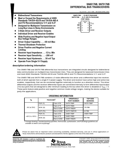
PACKAGING INFORMATIONOrderable Device Status(1)PackageType PackageDrawingPins PackageQtyEco Plan(2)Lead/Ball Finish MSL Peak Temp(3)SN65176BD ACTIVE SOIC D875Green(RoHS&no Sb/Br)CU NIPDAU Level-1-260C-UNLIMSN65176BDE4ACTIVE SOIC D875Green(RoHS&no Sb/Br)CU NIPDAU Level-1-260C-UNLIMSN65176BDG4ACTIVE SOIC D875Green(RoHS&no Sb/Br)CU NIPDAU Level-1-260C-UNLIMSN65176BDR ACTIVE SOIC D82500Green(RoHS&no Sb/Br)CU NIPDAU Level-1-260C-UNLIMSN65176BDRE4ACTIVE SOIC D82500Green(RoHS&no Sb/Br)CU NIPDAU Level-1-260C-UNLIMSN65176BDRG4ACTIVE SOIC D82500Green(RoHS&no Sb/Br)CU NIPDAU Level-1-260C-UNLIMSN65176BP ACTIVE PDIP P850Pb-Free(RoHS)CU NIPDAU N/A for Pkg TypeSN65176BPE4ACTIVE PDIP P850Pb-Free(RoHS)CU NIPDAU N/A for Pkg TypeSN75176BD ACTIVE SOIC D875Green(RoHS&no Sb/Br)CU NIPDAU Level-1-260C-UNLIMSN75176BDE4ACTIVE SOIC D875Green(RoHS&no Sb/Br)CU NIPDAU Level-1-260C-UNLIMSN75176BDG4ACTIVE SOIC D875Green(RoHS&no Sb/Br)CU NIPDAU Level-1-260C-UNLIMSN75176BDR ACTIVE SOIC D82500Green(RoHS&no Sb/Br)CU NIPDAU Level-1-260C-UNLIMSN75176BDRE4ACTIVE SOIC D82500Green(RoHS&no Sb/Br)CU NIPDAU Level-1-260C-UNLIMSN75176BDRG4ACTIVE SOIC D82500Green(RoHS&no Sb/Br)CU NIPDAU Level-1-260C-UNLIMSN75176BP ACTIVE PDIP P850Pb-Free(RoHS)CU NIPDAU N/A for Pkg TypeSN75176BPE4ACTIVE PDIP P850Pb-Free(RoHS)CU NIPDAU N/A for Pkg TypeSN75176BPSR ACTIVE SO PS82000Green(RoHS&no Sb/Br)CU NIPDAU Level-1-260C-UNLIMSN75176BPSRG4ACTIVE SO PS82000Green(RoHS&no Sb/Br)CU NIPDAU Level-1-260C-UNLIM(1)The marketing status values are defined as follows:ACTIVE:Product device recommended for new designs.LIFEBUY:TI has announced that the device will be discontinued,and a lifetime-buy period is in effect.NRND:Not recommended for new designs.Device is in production to support existing customers,but TI does not recommend using this part in a new design.PREVIEW:Device has been announced but is not in production.Samples may or may not be available.OBSOLETE:TI has discontinued the production of the device.(2)Eco Plan-The planned eco-friendly classification:Pb-Free(RoHS),Pb-Free(RoHS Exempt),or Green(RoHS&no Sb/Br)-please check /productcontent for the latest availability information and additional product content details.TBD:The Pb-Free/Green conversion plan has not been defined.Pb-Free(RoHS):TI's terms"Lead-Free"or"Pb-Free"mean semiconductor products that are compatible with the current RoHS requirements for all6substances,including the requirement that lead not exceed0.1%by weight in homogeneous materials.Where designed to be soldered at high temperatures,TI Pb-Free products are suitable for use in specified lead-free processes.Pb-Free(RoHS Exempt):This component has a RoHS exemption for either1)lead-based flip-chip solder bumps used between the die andpackage,or2)lead-based die adhesive used between the die and leadframe.The component is otherwise considered Pb-Free(RoHS compatible)as defined above.Green(RoHS&no Sb/Br):TI defines"Green"to mean Pb-Free(RoHS compatible),and free of Bromine(Br)and Antimony(Sb)based flame retardants(Br or Sb do not exceed0.1%by weight in homogeneous material)(3)MSL,Peak Temp.--The Moisture Sensitivity Level rating according to the JEDEC industry standard classifications,and peak solder temperature.Important Information and Disclaimer:The information provided on this page represents TI's knowledge and belief as of the date that it is provided.TI bases its knowledge and belief on information provided by third parties,and makes no representation or warranty as to the accuracy of such information.Efforts are underway to better integrate information from third parties.TI has taken and continues to take reasonable steps to provide representative and accurate information but may not have conducted destructive testing or chemical analysis on incoming materials and chemicals.TI and TI suppliers consider certain information to be proprietary,and thus CAS numbers and other limited information may not be available for release.In no event shall TI's liability arising out of such information exceed the total purchase price of the TI part(s)at issue in this document sold by TI to Customer on an annual basis.TAPE AND REEL INFORMATIONDevice Package Pins Site ReelDiameter(mm)ReelWidth(mm)A0(mm)B0(mm)K0(mm)P1(mm)W(mm)Pin1QuadrantSN65176BDR D8FMX33012 6.4 5.2 2.1812Q1 SN75176BDR D8FMX33012 6.4 5.2 2.1812Q1 SN75176BPSR PS8MLA330168.2 6.6 2.51216Q1TAPE AND REEL BOX INFORMATIONDevice Package Pins Site Length(mm)Width(mm)Height(mm)SN65176BDR D8FMX338.1340.520.64SN75176BDR D8FMX338.1340.520.64SN75176BPSR PS8MLA342.9336.628.58IMPORTANT NOTICETexas Instruments Incorporated and its subsidiaries (TI)reserve the right to make corrections,modifications,enhancements,improvements,and other changes to its products and services at any time and to discontinue any product or service without notice.Customers should obtain the latest relevant information before placing orders and should verify that such information is current and complete.All products are sold subject to TI’s terms and conditions of sale supplied at the time of order acknowledgment.TI warrants performance of its hardware products to the specifications applicable at the time of sale in accordance with TI’s standard warranty.Testing and other quality control techniques are used to the extent TI deems necessary to support this warranty.Except where mandated by government requirements,testing of all parameters of each product is not necessarily performed.TI assumes no liability for applications assistance or customer product design.Customers are responsible for their products and applications using TI components.To minimize the risks associated with customer products and applications,customers should provide adequate design and operating safeguards.TI does not warrant or represent that any license,either express or implied,is granted under any TI patent right,copyright,mask work right,or other TI intellectual property right relating to any combination,machine,or process in which TI products or services are rmation published by TI regarding third-party products or services does not constitute a license from TI to use such products or services or a warranty or endorsement e of such information may require a license from a third party under the patents or other intellectual property of the third party,or a license from TI under the patents or other intellectual property of TI.Reproduction of information in TI data books or data sheets is permissible only if reproduction is without alteration and isaccompanied by all associated warranties,conditions,limitations,and notices.Reproduction of this information with alteration is an unfair and deceptive business practice.TI is not responsible or liable for such altered documentation.Resale of TI products or services with statements different from or beyond the parameters stated by TI for that product or service voids all express and any implied warranties for the associated TI product or service and is an unfair and deceptive business practice.TI is not responsible or liable for any such statements.TI products are not authorized for use in safety-critical applications (such as life support)where a failure of the TI product would reasonably be expected to cause severe personal injury or death,unless officers of the parties have executed an agreementspecifically governing such use.Buyers represent that they have all necessary expertise in the safety and regulatory ramifications of their applications,and acknowledge and agree that they are solely responsible for all legal,regulatory and safety-related requirements concerning their products and any use of TI products in such safety-critical applications,notwithstanding any applications-related information or support that may be provided by TI.Further,Buyers must fully indemnify TI and itsrepresentatives against any damages arising out of the use of TI products in such safety-critical applications.TI products are neither designed nor intended for use in military/aerospace applications or environments unless the TI products are specifically designated by TI as military-grade or "enhanced plastic."Only products designated by TI as military-grade meet military specifications.Buyers acknowledge and agree that any such use of TI products which TI has not designated as military-grade is solely at the Buyer's risk,and that they are solely responsible for compliance with all legal and regulatory requirements in connection with such use.TI products are neither designed nor intended for use in automotive applications or environments unless the specific TI products are designated by TI as compliant with ISO/TS 16949requirements.Buyers acknowledge and agree that,if they use any non-designated products in automotive applications,TI will not be responsible for any failure to meet such requirements.Following are URLs where you can obtain information on other Texas Instruments products and application solutions:ProductsApplications AmplifiersAudioDataConvertersAutomotiveDSPBroadband InterfaceDigital Control LogicMilitary Power MgmtOptical Networking MicrocontrollersSecurity RFIDTelephony Low PowerVideo &ImagingWireless Wireless Mailing Address:Texas Instruments,Post Office Box 655303,Dallas,Texas 75265Copyright ©2007,Texas Instruments Incorporated 元器件交易网。
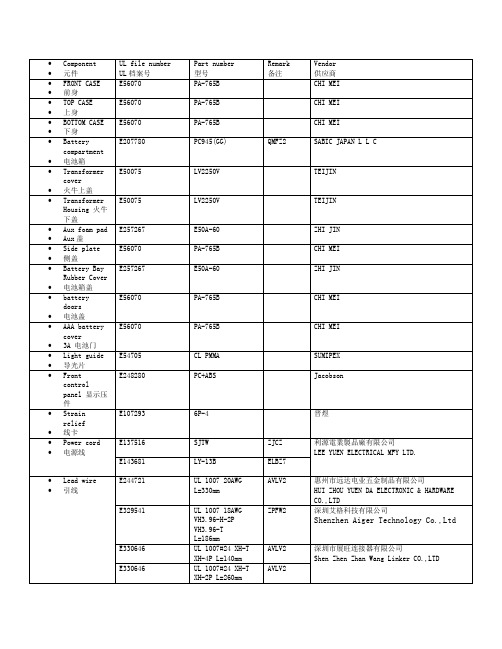
•Component •元件UL file numberUL档案号Part number型号Remark备注Vendor供应商•FRONT CASE•前身E56070 PA-765B CHI MEI•TOP CASE•上身E56070 PA-765B CHI MEI•BOTTOM CASE•下身E56070 PA-765B CHI MEI•Batterycompartment•电池箱E207780 PC945(GG) QMFZ2 SABIC JAPAN L L C•Transformercover•火牛上盖E50075 LV2250V TEIJIN•TransformerHousing 火牛下盖E50075 LV2250V TEIJIN•Aux foam pad•Aux盖E257267 E50A-60 ZHI JIN•Side plate•侧盖E56070 PA-765B CHI MEI•Battery BayRubber Cover•电池箱盖E257267 E50A-60 ZHI JIN•batterydoors•电池盖E56070 PA-765B CHI MEI•AAA batterycover•3A 电池门E56070 PA-765B CHI MEI•Light guide•导光片E54705 CL PMMA SUMIPEX•Frontcontrolpanel 显示压件E248280 PC+ABS Jacobson•Strainrelief•线卡E107293 6P-4 晋煜•Power cord •电源线E137516 SJTW ZJCZ 利源電業製品廠有限公司LEE YUEN ELECTRICAL MFY LTD. E143681 LY-13B ELBZ7•Lead wire •引线E244721 UL 1007 20AWGL=330mmAVLV2 惠州市远达电业五金制品有限公司HUI ZHOU YUEN DA ELECTRONIC & HARDWARECO.,LTDE329541 UL 1007 18AWGVH3.96-H-2PVH3.96-TL=186mmZPFW2 深圳艾格科技有限公司Shenzhen Aiger Technology Co.,LtdE330646 UL 1007#24 XH-TXH-4P L=140mmAVLV2 深圳市展旺连接器有限公司Shen Zhen Zhan Wang Linker CO.,LTDE330646 UL 1007#24 XH-TXH-2P L=260mmAVLV2E330646 UL 2547#28 PH-TPH-3P L=260mmAVLV2E330646 UL 2547#28 PH-TPH-3P L=220mmAVLV2E330646 UL 1185 22AWG XH-T XH-2P L=150mmAVLV2•Integralfuse •保险丝E340427 SFC0800A(800mA/250V FastActing Glass TubeFuse)JDYX 瑞卓电子(东莞)有限公司Dongguan Reomax Electronics Co., LTD•Fuse Holder •保险丝座E239034 H3(10A/250V)IZLT2 惠州市海牛電子有限公司HUIZHOU HINEW ELECTRIC APPLIANCE CO.,LTD.变压器材料清單/ MATERIAL LISTNO. MATERIAL DESCRIPTION Ul file MANUFACTURERS / SUPPLIERS1. 膠芯/Bobbin 最小0.71mm厚尼龍66 101(r9)一層minimum 0.71mm thick PA66101(r9) one layerUL:E41938 杜邦/E I Dupont De Nemours & Co Inc2 膠套/Shroud 最小0.50mm厚尼龍66 101(r9)一層minimum 0.50mm thick PA66101(r9) one layerUL:E41938 杜邦/E I Dupont De Nemours & Co Inc3 初級線圈PrimaryWinding 聚氨酯漆包線MW75C(130℃) 或Polyurethane Wire,MW75C(130℃)UL:E258125 河源天裕電子塑膠有限公司He Yuan Sky Wealth Electronic And PlasticCo Ltd.4 初級跨線絕緣Pri. windingcrossoverinsulation CT25聚脂膠紙/CT-25 Polyestertape厚度:0.05mm*2 層/Thickness:0.05mm*2 layersUL:E165111 靖江亞華壓敏黏膠有限公司Jingjiang Yahua Pressure Sensitive Glue COLTD5 溫度保險Thermal Fuse Type: A4-F130 Deg.C ( 250V/2A)UL:E140847 雅寶電子有限公司/Aupo Electronics Inc.6 初級引線Primary Leads UL-1672 AWG #22 VW-1 300V105Deg.CUL:E191230UL:E189674UL:E211048UL:E214859恒輝(香港)發展有限公司Ever Bright (Hongkong) development CompanyLimited.深圳东聚Shenzhen Dong Ju Wire & CableCo.,Ltd.琦富瑞Qifurui Electronics co阳泰氟电线电缆YANGTAI WIRE & CABLE CO LTD7 初級引線Primary Leads 聚氨酯漆包線MW75C(130℃) 或Polyurethane Wire,MW75C(130℃)or聚氨酯漆包線MW79C(155℃)Polyurethane Wire,MW79C(155℃)UL:E258125UL:E201757河源天裕電子塑膠有限公司He Yuan Sky Wealth Electronic And PlasticCo Ltd.太平洋電線電纜深圳公司Pacific ElectricWire&Cable(shenzhen)Co.,Ltd.8 次級引線SecondaryLeads UL-1015 AWG #20 VW-1 600V105Deg.CUL:E191230UL:E189674UL:E211048UL:E214859恒輝(香港)發展有限公司Ever Bright(Hongkong) development Company Limited.深圳东聚Shenzhen Dong Ju Wire & CableCo.,Ltd.琦富瑞Qifurui Electronics co阳泰氟电线电缆YANGTAI WIRE & CABLE CO LTD9 次級引線SecondaryLeads CT25聚脂膠紙/CT-25 Polyestertape厚度:0.05mm*3 層/UL:E165111 靖江亞華壓敏黏膠有限公司Jingjiang Yahua Pressure Sensitive Glue COLTD.Thickness:0.05mm*3 layers聚酯膠片型號:MYLAR EL21 0.25mm厚PET film Type:MYLAR EL21 0.25mmThickUL:E93687 杜邦帝人/ Dupont Teijin Films U S L P10 外層絕緣Outinsulation CT25聚脂膠紙/CT-25 Polyestertape厚度:0.05mm*3 層/Thickness:0.05mm*3 layers聚酯膠片型號:MYLAR EL21 0.25mm厚PET film Type:MYLAR EL21 0.25mmThickUL:E165111UL:E93687靖江亞華壓敏黏膠有限公司Jingjiang Yahua Pressure Sensitive Glue COLTD.杜邦帝人/ Dupont Teijin Films U S L P11 鐵芯片LaminationCore EI-57 硅鋼片(H18 黑) 片厚0.50,疊厚35.3+/-0.5mmEI-57 silicon steel sheet(H18black), thickness:0.50mm,depth thickness:35.3+/-0.5mmN/A 東莞東駿電器有限公司Dongguan Dongjun Electrical Appliances Co.,Ltd.12 安裝架/Bracket 冷軋板鍍鋅Cold rolled Steel with Zinc-coatedN/A 東莞駿豐五金製品廠Dongguan JunFeng MetalManufactory13 屏蔽殼/Endbell 冷軋板鍍鋅Cold rolled Steel with Zinc-coatedN/A 東莞駿豐五金製品廠Dongguan JunFeng MetalManufactory14 次級連接器Secondaryconnector Housing: JS-1121-02 & Terminal:JS-1121-THousing: A3963H-2P & Terminal:A3963-TPUL: E113875UL: E326732喬訊電子有限公司Chyao shiunn electronicIndustrial Ltd.長江連接器有限公司ChangJiang Connectors CoLtd15 浸漬/Impregnation Insulating Varnish/絕緣油Type: 8562/C, class FUL:E200154 恒昌化學塗料公司HANG CHEUNG PETROCHEMICALLTD。

产品手册PRODUCT MANUAL(北京︶有限公司并一直致力于为工业智能控制、医疗设备、轨道交通、智能交通以及智能家居等领域提供更优质的产品与服务。
公司具有深厚的文化底蕴,由多位有欧美留学、工作经历的归国人员创办,坚实的理论功底和丰富的芯片设计经验奠定了启珑微电子的高起点和高水准,并迅速成长为业内具有自主知识产权的中国IC设计品牌之一。
产品手册01序号产品型号封装形式产品概述兼容型号1CLM811HST-AXC TQFP-48SL811HST-AXC 2CLCP82C55AZ DIP-40CP82C55AZ 3CLIP82C55AZ DIP-40IP82C55AZ 4CLCS82C55AZ PLCC-44CS82C55AZ 5CLIS82C55AZ PLCC-44IS82C55AZ 6CLCQ82C55AZ MQFP-44CQ82C55AZ 7CLIQ82C55AZ MQFP-44IQ82C55AZ 8CLID82C55AZ DIP-40ID82C55A 9CLMD82C55A/B DIP-40MD82C55A/B 10CLMD82C55QA DIP-40MD82C55QA 11CLM65HVD230D SOIC-8SN65HVD230D 12CLM65HVD230QD SOIC-8SN65HVD230QD 13CLM65HVD231D SOIC-8SN65HVD231D 14CLM65HVD231QD SOIC-8SN65HVD231QD 15CLM65HVD232D SOIC-8SN65HVD232D 16CLM65HVD232QD SOIC-8SN65HVD232QD 17CLM65HVD233D SOIC-8具有待机模式和环回功能的 3.3V SN65HVD233D 18CLM65HVD233HD SOIC-8具有待机模式和环回功能的 3.3V SN65HVD233HD 19CLM65HVD233QDRQ1SOIC-8具有待机模式和环回功能的 3.3V SN65HVD233QDRQ120CLM65HVD233MDREP SOIC-8具有待机模式和环回功能的 3.3V SN65HVD233MDREP产品手册02序号产品型号封装形式产品概述兼容型号21CLM65HVD234D SOIC-8SN65HVD234D 22CLM65HVD234QDRQ1SOIC-8SN65HVD234QDRQ123CLM65HVD235D SOIC-8SN65HVD235D 24CLM65HVD235QDRQ1SOIC-8SN65HVD235QDRQ125CLM75176BPS SOIC-8SN75176BPSR 26CLM75176BDR SOIC-8SN75176BDR 27CLM75176ADR SOIC-8SN75176ADR 28CLM75176AP DIP-8SN75176AP 29CLM76176BP DIP-8SN75176BP 30CLM75179BPS SOIC-8SN75179BPS 31CLM75179BDR SOIC-8SN75179BDR 32CLM75179AP DIP-8SN75179AP 33CLM75179BP DIP-8SN75179BP 34CLM65HVD08D SOIC-8SN65HVD08D 35CLM65HVD08P DIP-8SN65HVD08P 36CLM65HVD75D SOIC-8具有IEC ESD保护功能和20Mbps的SN65HVD75D 37CLM65HVD75DGK VSSOIC-8具有IEC ESD保护功能和20Mbps的SN65HVD75DGK 38CLM65HVD75DRBT VDFN-8具有IEC ESD保护功能和20Mbps的SN65HVD75DRBT 39CLM3085CPA+DIP-8(10Mbps)、限摆率RS-485/MAX3085CPA+40CLM3085EPA+DIP-8(10Mbps)、限摆率RS-485/MAX3085EPA+产品手册03序号产品型号封装形式产品概述兼容型号41CLM3085EEPA DIP-8(10Mbps)、限摆率RS-485/MAX3085EEPA 42CLM3085CSA+T SOIC-8(10Mbps)、限摆率RS-485/MAX3085CSA+43CLM3085ECSA+T MSOIC-8(10Mbps)、限摆率RS-485/MAX3085ECSA+T 44CLM3085ESA+T SOIC-8(10Mbps)、限摆率RS-485/MAX3085ESA+45CLM3085EESA+T SOIC-8(10Mbps)、限摆率RS-485/MAX3085EESA+46CLM3088CSA+T SOIC-8MAX3088CSA+T 47CLM3088ECSA+T SOIC-8MAX3088ECSA+T 48CLM3088ESA+T SOIC-8MAX3088ESA+T 49CLM3088EESA+T SOIC-8MAX3088EESA+T 50CLM3088CPA+DIP-8MAX3088CPA+51CLM3088ECPA+DIP-8MAX3088ECPA+52CLM3088EPA+DIP-8MAX3088EPA+53CLM3088EEPA+DIP-8MAX3088EEPA+54CLM485CPA+DIP-8低功耗、限摆率、RS-485/RS-422MAX485CPA+55CLM485ECPA+DIP-8低功耗、限摆率、RS-485/RS-422MAX485ECPA+56CLM485EPA+DIP-8低功耗、限摆率、RS-485/RS-422MAX485EPA+57CLM485EEPA+DIP-8低功耗、限摆率、RS-485/RS-422MAX485EEPA+58CLM485CSA+SOIC-8低功耗、限摆率、RS-485/RS-422MAX485CSA+59CLM485ESA+SOIC-8低功耗、限摆率、RS-485/RS-422MAX485ESA+60CLM485EESA+SOIC-8低功耗、限摆率、RS-485/RS-422MAX485EESA+产品手册04序号产品型号封装形式产品概述兼容型号61CLM3490CSA+SOIC-8 3.3V供电、10Mbps、限摆率、真MAX3490CSA+62CLM3490ECSA+SOIC-8 3.3V供电、10Mbps、限摆率、真MAX3490ESA+63CLM3490ESA+SOIC-8 3.3V供电、10Mbps、限摆率、真MAX3490ESA+64CLM3490EESA+SOIC-8 3.3V供电、10Mbps、限摆率、真MAX3490EESA+65CLM3491CSD SOP-14 3.3V供电、10Mbps、限摆率、真MAX3491CSD+66CLM3491ECSD+SOP-14 3.3V供电、10Mbps、限摆率、真MAX3491ECSD+67CLM3491ESD+SOP-14 3.3V供电、10Mbps、限摆率、真MAX3491ESD+68CLM3491EESD+SOP-14 3.3V供电、10Mbps、限摆率、真MAX3491EESD+69CLM490CSA+SOIC-8低功耗、限摆率、RS-485/RS-422MAX490CSA+70CLM490ECSA+SOIC-8低功耗、限摆率、RS-485/RS-422MAX490ECSA+71CLM490ESA+SOIC-8低功耗、限摆率、RS-485/RS-422MAX490ESA+72CLM490EESA+SOIC-8低功耗、限摆率、RS-485/RS-422MAX490EESA+73CLM490CPA+DIP-8低功耗、限摆率、RS-485/RS-422MAX490CPA+74CLM490ECPA+DIP-8低功耗、限摆率、RS-485/RS-422MAX490ECPA+75CLM490EPA+DIP-8低功耗、限摆率、RS-485/RS-422MAX490EPA+76CLM490EEPA+DIP-8低功耗、限摆率、RS-485/RS-422MAX490EEPA+77CLM488CSA+SOIC-8低功耗、限摆率、RS-485/RS-422MAX488CSA+78CLM488ECSA+SOIC-8低功耗、限摆率、RS-485/RS-422MAX488ECSA+79CLM488ESA+SOIC-8低功耗、限摆率、RS-485/RS-422MAX488ESA+80CLM488EESA+SOIC-8低功耗、限摆率、RS-485/RS-422MAX488EESA+产品手册序号产品型号封装形式产品概述兼容型号81CLM488CPA+DIP-8MAX488CPA+82CLM488ECPA+DIP-8MAX488ECPA+83CLM488EPA+DIP-8MAX488EPA+84CLM488EEPA+DIP-8MAX488EEPA+85CLM232CSE SOIC-16MAX232CSE+T86CLM232ECSE SOIC-16MAX232ECSE+87CLM232ESE SOIC-16MAX232ESE+T88CLM232EESE SOIC-16MAX232EESE+T89CLM232CPE DIP-16MAX232CPE+90CLM232ECPE DIP-16MAX232ECPE+91CLM232EPE DIP-16MAX232EPE+92CLM232EEPE DIP-16MAX232EEPE+93CLM232CWE SOIC-16MAX232CWE+T94CLM232ECWE SOIC-16MAX232ECWE+T95CLM232EWE SOIC-16MAX232EWE+T96CLM232EEWE SOIC-16MAX232EEWE+T97CLM232ACWE SOIC-16MAX232ACWE+T98CLM232AEWE SOIC-16MAX232AEWE+99CLM3232CSE SOIC-16MAX3232CSE+T 100CLM3232ECSE SOIC-16MAX3232ECSE+T05产品手册06序号产品型号封装形式产品概述兼容型号101CLM3232ESE SOIC-16MAX3232ESE+T 102CLM3232EESE SOIC-16MAX3232EESE+T 103CLM1302S SOIC-8DS1302S+T&R 104CLM1302SN+SOIC-8DS1302SN+T&R 105CLM1302Z+T SOIC-8DS1302Z+T&R 106CLM1302ZN+SOIC-8DS1302ZN+T&R 107CLM1302+DIP-8DS1302+108CLM1302N+DIP-8DS1302N+109CLM307Z+SOIC-8DS1307Z+T&R 110CLM1307ZN+SOIC-8DS1307ZN+T&R 111CLM1307+DIP-8DS1307+112CLM1307N+DIP-8DS1307N+113CLM4717EUB+MSOP-10拟开关MAX4717EUB+114CLM231N/NOPB DIP-8LM231N/NOPB 115CLM231AN/NOPB DIP-8LM231AN/NOPB 116CLM331N/NOPB DIP-8LM331N/NOPB 117CLM331AN/NOPB DIP-8LM331AN/NOPB 118CLM298N Multiwatt-15L298N 119CLM298P POWERSO-20L298P 120CLM2543CDW SOIC-20TLC2543CDW产品手册07序号产品型号封装形式产品概述兼容型号121CLM2543IDW SOIC-20TLC2543IDW 122CLM2543CDB SSOP-20TLC2543CDB 123CLM2543IDB SSOP-20TLC2543IDB 124CLM2543CN DIP-20TLC2543CN 125CLM2543IN DIP-20TLC2543IN 126CLM1543CDW SOIC-20TLC1543CDW 127CLM1543IDW SOIC-20TLC1543IDW 128CLM1543CN DIP-20TLC1543CN 129CLM1543IN DIP-20TLC1543IN 130CLM5615CDGK VSSOIC-8趋稳时间为12.5us并具备上电复位功能的10位、单通道、低功耗DAC TLC5615CDGK 131CLM5615IDGK VSSOIC-8趋稳时间为12.5us并具备上电复位功能的10位、单通道、低功耗DAC TLC5615IGGK 132CLM5615CD SOIC-8趋稳时间为12.5us并具备上电复位功能的10位、单通道、低功耗DAC TLC5615CD 133CLM5615ID SOIC-8趋稳时间为12.5us并具备上电复位功能的10位、单通道、低功耗DAC TLC5615ID 134CLM5615CP DIP-8趋稳时间为12.5us并具备上电复位功能的10位、单通道、低功耗DAC TLC5615CP 135CLM5615IP DIP-8趋稳时间为12.5us并具备上电复位功能的10位、单通道、低功耗DAC TLC5615IP 136CLM3616-00SOP-14IW3616-00137CLM3616-01SOP-14IW3616-01138CLM3617-00SOP-14IW3617-00139CLM3617-01SOP-14IW3617-01140CLM3630-00SOP-14IW3630-00产品手册序号产品型号封装形式产品概述兼容型号141CLM1100-0001BGA-128ASIC从站控制ET1100-0001142CLM1100-0002BGA-128ASIC从站控制ET1100-0002143CLM1100-0003BGA-128ASIC从站控制ET1100-0003144CLM1200-0001QFN-48ASIC从站控制ET1200-0001145CLM1200-0002QFN-48ASIC从站控制ET1200-0002146CLM1200-0003QFN-48ASIC从站控制ET1200-0003147CLM8656ARZ SOIC-8AD8656ARZ148CLM8656ARMZ MSOIC-8AD8656ARMZ149CLM1040T/CM,118SOIC-8TJA1040T/CM,118 150CLM1042T/CM,118SOIC-8TJA1042T/CM,118 151CLM1050T/CM,118SOIC-8TJA1050T/CM,118 152CLM1051T/CM,118SOIC-8TJA1051T/CM,118 153CLM82C250T/YM SOIC-8PCA82C250T/YM 154CLM82C251T/YM SOIC-8PCA82C251T/YM 155CLMEE80C196KC20PLCC-68EE80C196KC20 156CLMEN80C196KC20PLCC-68EN80C196KC20 157CLMN80C196KC20PLCC-68N80C196KC20 158CLMTN80C196KC20PLCC-68TN80C196KC20 159CLMEE87C196KC20PLCC-68EE87C196KC20 160CLMEN87C196KC20PLCC-68EN87C196KC2008产品手册09序号产品型号封装形式产品概述兼容型号161CLMN87C196KC20PLCC-68N87C196KC20162CLMTN87C196KC20PLCC-68TN87C196KC20163CLM8051F020-GQ TQFP-100C8051F020-GQ 164CLM8051F021-GQ TQFP-64C8051F021-GQ 165CLM8051F330-GM VFQFN-20C8051F330-GM 166CLM8051F500-IQ TQFP-48C8051F500-IQ 167CLM8051F500-IM VFQFN-48C8051F500-IM 168CLM8051F502-IQ LQFP-32C8051F502-IQ 169CLM8051F502-IM QFN-32C8051F502-IM170CLM08D1500CIYB/NOPB HLQFP-128ADC08D1500CIYB/NOPB 171CLM083000CIYB/NOPB HLQFP-128ADCADC083000CIYB/NOPB 172CLM10AQ190AVTPY EBGA-38010位5GSPS ADC EV10AQ190AVTPY 173CLM9680BCPZ-1250LFCSP-64双通道14位1GSPS ADC AD9680BCPZ-1250174CLM9739BBCZ BGA-16014位、2.5 GSPS、RF数模AD9739BBCZ 175CLM9779ABSVZ TQFP-100双通道16位1GSPS DAC AD9779ABSVZ 176CLM12DS130AVZPY FPBGA-19612位3GSPS DAC EV12DS130AVZPY 177CLM12DS460AVZP FPBGA-19612位6.4GSPS DAC EV12DS460AVZP 178CLM9434BCPZ-370LFCSP-5612位370MSPS ADC AD9434BCPZ-370179CLM9434BCPZ-500LFCSP-5612位500MSPS ADC AD9434BCPZ-500180CLM4149IRGZTVQFN-4814位250MSPS ADCADS4149IRGZT产品手册10序号产品型号封装形式产品概述兼容型号181CLM9467BCPZ-200LFCSP-7216位200MSPS ADC AD9467BCPZ-200182CLM9467BCPZ-250LFCSP-7216位250MSPS ADC AD9467BCPZ-250183CLM9656BCPZ-125LFCSP-56四通道16位125MSPS ADC AD9656BCPZ-125184CLM9245BCPZ-40LFCSP-3214位40MSPS ADC AD9245BCPZ-40185CLM9245BCPZ-65LFCSP-3214位65MSPS ADC AD9245BCPZ-80186CLM9245BCPZ-80LFCSP-3214位80MSPS ADC AD9245BCPZ-80187CLM9783BCPZ LFCSP-72双通道16位500MSPS DAC AD9783BCPZ 188CLM7656BSTZ-REEL LQFP-64六通道16位250KSPS ADC AD7656BSTZ-REEL 189CLM7960BCPZLFCSP-3218位2MSPS ADC AD7960BCPZ190CLM128S102CIMTX/NOPB TSSOP-1612位1MSPS ADC ADC128S102CIMTX/NOPB 191CLM5638IDR SOIC-8DACTLV5638IDR 192CLM7606BSTZ LQFP-64AD7606BSTZ 193CLM9625BBPZ-2.5BGA-19612位2.6GSPS ADC AD9625BBPZ-2.5194CLM9164BBCZ BGA-16516位12GSPS DAC AD9164BBCZ 195CLM9154BCPZ LFCSP-88四通道16位2.4GSPS DAC AD9154BCPZ 196CLM2160IUK#PBF QFN-4816位25MSPS ADC LTC2160IUK#PBF 197CLM9652BBCZ-310BGA-144双通道16位310MSPS ADC AD9652BBCZ-310198CLM7779ACPZ-RL LFCSP-6424位16KSPS ADC AD7779ACPZ-RL 199CLM9208BBPZ-3000BGA-196双通道14位3GSPS ADCAD9208BBPZ-3000200CLM320VC33PGE120LQFP-144TMS320VC33PGE120产品手册序号产品型号封装形式产品概述兼容型号201CLM320VC33PGEA120LQFP-144TMS320VC33PGEA120 202CLM320VC33PGE150LQFP-144TMS320VC33PGE150203CLM320VC5402PGE100LQFP-144TMS320VC5402PGE100 204CLM320F28335PGFA LQFP-176TMS320F28335PGFA205CLM320LF2406APZA LQFP-100TMS320LF2406APZA206CLM320LF2406APZS LQFP-100TMS320LF2406APZS207CLM320LF2407APGES LQFP-144TMS320LF2407APGES208CLM320LF2407APGEA LQFP-144TMS320LF2407APGEA 209CLM320C6713BPYP200HLQFP-208TMS320C6713BPYP200 210CLM320C6713BZDP225BGA-272TMS320C6713BZDP225 211CLM320C6713BGDP225BGA-272TMS320C6713BGDP225 212CLM320C6713BZDP300BGA-272TMS320C6713BZDP300 213CLM320C6713BGDG300BGA-272TMS320C6713BGDP30011邮箱:*******************。
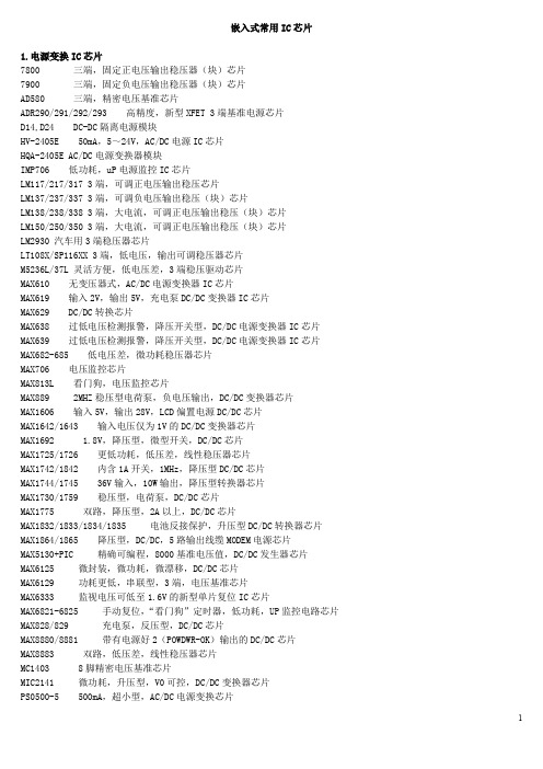
嵌入式常用IC芯片1.电源变换IC芯片7800 三端,固定正电压输出稳压器(块)芯片7900 三端,固定负电压输出稳压器(块)芯片AD580 三端,精密电压基准芯片ADR290/291/292/293 高精度,新型XFET 3端基准电源芯片D14,D24 DC-DC隔离电源模块HV-2405E 50mA,5~24V,AC/DC电源IC芯片HQA-2405E AC/DC电源变换器模块IMP706 低功耗,uP电源监控IC芯片LM117/217/317 3端,可调正电压输出稳压芯片LM137/237/337 3端,可调负电压输出稳压(块)芯片LM138/238/338 3端,大电流,可调正电压输出稳压(块)芯片LM150/250/350 3端,大电流,可调正电压输出稳压(块)芯片LM2930 汽车用3端稳压器芯片LT108X/SP116XX 3端,低电压,输出可调稳压器芯片M5236L/37L 灵活方便,低电压差,3端稳压驱动芯片MAX610 无变压器式,AC/DC电源变换器IC芯片MAX619 输入2V,输出5V,充电泵DC/DC变换器IC芯片MAX629 DC/DC转换芯片MAX638 过低电压检测报警,降压开关型,DC/DC电源变换器IC芯片MAX639 过低电压检测报警,降压开关型,DC/DC电源变换器IC芯片MAX682-685 低电压差,微功耗稳压器芯片MAX706 电压监控芯片MAX813L 看门狗,电压监控芯片MAX889 2MHZ稳压型电荷泵,负电压输出,DC/DC变换器芯片MAX1606 输入5V,输出28V,LCD偏置电源DC/DC芯片MAX1642/1643 输入电压仅为1V的DC/DC变换器芯片MAX1692 1.8V,降压型,微型开关,DC/DC芯片MAX1725/1726 更低功耗,低压差,线性稳压器芯片MAX1742/1842 内含1A开关,1MHz,降压型DC/DC芯片MAX1744/1745 36V输入,10W输出,降压型转换器芯片MAX1730/1759 稳压型,电荷泵,DC/DC芯片MAX1775 双路,降压型,2A以上,DC/DC芯片MAX1832/1833/1834/1835 电池反接保护,升压型DC/DC转换器芯片MAX1864/1865 降压型,DC/DC,5路输出线缆MODEM电源芯片MAX5130+PIC 精确可编程,8000基准电压值,DC/DC发生器芯片MAX6125 微封装,微功耗,微漂移,DC/DC芯片MAX6129 功耗更低,串联型,3端,电压基准芯片MAX6333 监视电压可低至1.6V的新型单片复位IC芯片MAX6821-6825 手动复位,“看门狗”定时器,低功耗,UP监控电路芯片MAX828/829 充电泵,反压型,DC/DC芯片MAX8880/8881 带有电源好2(POWDWR-OK)输出的DC/DC芯片MAX8883 双路,低压差,线性稳压器芯片MC1403 8脚精密电压基准芯片MIC2141 微功耗,升压型,V0可控,DC/DC变换器芯片PS0500-5 500mA,超小型,AC/DC电源变换芯片TOP1xx-2xx 无变压器,5W以上,AC/DC变换式精密开关电源IC芯片TL499AC 可调线型串联稳压器和升压型开关稳压器(合成稳压器)芯片TPS7350 5V固定输出,掉电延时复位,低压差稳压器芯片W431 3端,可调式电压基准芯片YA-S AC/DC电源变换器模块2.数字温度传感器AD526 增益可编程运算放大器芯片AD620 低功耗,高精密度仪器用运放芯片AD623 单电源Rail-Rail仪表运放芯片AD625 增益可编程运算放大器芯片AD626 单电源差分运算放大器芯片AD7416 带IIC接口,10位低功耗数字温度传感器芯片AD8571/8572/8574 0温漂,单电源,运算放大器芯片AD8591/8592/8594 带节能控制端的CMOS,单电源工作,满电源输入输出,运算放大器芯片DS1620 数字式温度传感器IC芯片DS1621 数字式温度传感器IC芯片及恒温控制器IC芯片DS1625 数字温度计和控温器芯片DS1629 2线接口,带有实时时钟的温度传感器芯片DS1820 数字式温度传感器IC芯片ITT2301AF 射频功率放大器芯片LM76 带数字温度传感器,IIC总线接口,12位信号输出,测温芯片LM92 数字式温度传感器芯片MAX54xx 体积更小,256级,数字电位器芯片MAX4265~4270 超低失真,单+5V,300MHz,运算放大器芯片MAX4430/4431/4432/4433 高速(280MHz),高精度,宽频带,单/双运算放大器芯片MAX6627/6628 兼容SPI接口的远端结温检测器芯片MAX6629/6630/6631/6632 微型SOT封装,+-1摄氏度精度的数字温度传感器芯片MAX6657/6658/6659 +-1摄氏度的本地和远端结温检测器芯片OP193/293/493 精密,微功耗,运算放大器芯片OP177 超精密运算放大器芯片OP777 精密,微功耗,单电源,运算放大器芯片MIC91x 高速(100~350MHz)运算放大器芯片X9241 IIC接口,数字电位器(EEPOT)IC芯片X9312 数字电位器IC芯片X9313 数控电位器芯片X9511 PushPOT按钮控制电位器芯片3.电机控制及驱动芯片87C196MC 电机控制专用微处理器芯片CIPH9803 可编程步进电机控制IC芯片FR-Z240-7.5K 变频调速器芯片HEF4752V PWM大规模集成电路芯片IR2110 高压浮动MOSFET,栅极步进电机驱动器IC芯片LM628 直流电机运动控制芯片LM1542 无刷直流电机控制器芯片LMD18200 H桥组件电机驱动芯片MA818 3相PWM,变频调速专用控制器芯片MAX1749 微型直流电机驱动控制芯片MC33033 带温度补偿的直流电机控制器芯片ML4428 无传感器PWM,无刷直流电机控制器芯片MOC30xx 双向晶闸管电机控制驱动器(双向光电耦合器)IC芯片MTE1122 智能型电机驱动运放芯片PA03 大功率(1000w)运放电机驱动芯片PA21/25/26 双功率电机驱动运放芯片PA61 大功率运放电机驱动芯片PA85 高压,高速,大功率,运放驱动芯片PBL3772/PBM3960 高性能步进电机驱动IC芯片组PH2083 多模式步进电机控制器IC芯片PMM8713 步进电机专用控制芯片SA06 脉宽调制运放,电机驱动芯片SA60 脉宽调制型功放芯片SA866 可编程,全数字化,3相PWM,变频调速控制器IC芯片ST6210 通用电机驱动电路(MCU)IC芯片TDA1085C 通用电机速度控制器芯片UCx637XC9536 PWM型直流电机驱动芯片XC9536 步进电机CPLD控制芯片4.数字通信IC芯片及接口5G16C550ACM1330E/1550DACMTX16/ACMRX18ADM101EAM7910Core 01DS14C232C/232TDS26F31DS26C32DS3695/3696/3697/3698DS8921DS8922DS9637DS9638DS14185DS75176DS96172/96174DS96173/96175HT9200AICL232KX50xxLM1893LMx3162M303S/303RM-8888MAX48x/49xMAX202MAX202E/211E/213E/232E/241EMAX214MAX220/232/232AMAX250/251MAX1480A/1480BMAX3080E-3089EMAX3082MAX3100MAX3140MAX3222/3232MAX3224~3227MAX3238E/3248E常用集成电路功能简介型号功能简述1710 视频信号处理集成电路2274 延迟集成电路2800 红外遥控信号接收集成电路4094 移位寄存串入、并出集成电路4260 动态随机存储集成电路4464 存储集成电路4558 双运算放大集成电路5101 天线开关集成电路15105 充电控制集成电路15551 管理卡升压集成电路31085 射频电源集成电路74122 可重触发单稳态集成电路85712 场扫描信号校正处理集成电路85713 行扫描信号校正集成电路0206A 天线开关集成电路03VFG9 发射压控振荡集成电路1021AC 发射压控振荡集成电路1097C 升压集成电路140N 电源取样比较放大集成电路14DN363 伺服控制集成电路1N706 混响延时集成电路20810-F6096 存储集成电路2252B 微处理集成电路24C01ACEA 存储集成电路24C026 存储集成电路24C04 存储集成电路24C64 码片集成电路24LC16B 存储集成电路24LC65 电可改写编程只读存储集成电路27C1000PC-12 存储集成电路27C2000QC-90 存储集成电路27C20T 存储集成电路27C512 电可改写编程只读存储集成电路28BV64 码片集成电路28F004 版本集成电路32D54 电源、音频信号处理集成电路32D75 电源、音频信号处理集成电路32D92 电源中频放大集成电路4066B 电子开关切换集成电路424260SDJ 存储集成电路4270351/91B9905 中频放大集成电路4370341/90M9919 中频处理集成电路4580D 双运算放大集成电路47C1638AN-U337 微处理集成电路47C1638AU-353 微处理集成电路47C432GP 微处理集成电路47C433AN-3888 微处理集成电路49/4CR1A 中频放大集成电路5G052 发光二极管四位显示驱动集成电路5G24 运算放大集成电路5W01 双运算放大集成电路649/CRIA70612 中频放大集成电路673/3CR2A 多模转换集成电路74HC04 逻辑与非门集成电路74HC04D 六反相集成电路74HC123 单稳态集成电路74HC125 端口功能扩展集成电路74HC14N 六反相集成电路74HC157A 多路转换集成电路74HC165 移相寄存集成电路74HC245 总线收发集成电路74HC32 或门四2输入集成电路74HC374八D 触发集成电路74HC573D 存储集成电路74HCT157 多路转换双输入集成电路74HCT4046A 压控振荡集成电路74HCT4538D 单稳态集成电路74HCT4538N 触发脉冲集成电路74HCT86D 异或门四2输入集成电路74HCU04 与非门集成电路74LS125 端口功能扩展集成电路74LS373 锁存集成电路74LS393 计数双四位二进制集成电路74LS74双D 触发集成电路78014DFP 系统控制处理集成电路811N 伴音阻容偏置集成电路83D33 压控振荡集成电路87C52 微处理集成电路87CK38N-3584 微处理集成电路87CK38N-3627 微处理集成电路89C52 系统控制处理集成电路89C55 系统控制处理集成电路93C66 电可改写编程只读存储集成电路93LC56 电可改写编程存储集成电路9821K03 系统控制集成电路A1642P 背景歌声消除集成电路A701 红外遥控信号接收集成电路A7950 场频识别集成电路A8772AN 色差信号延迟处理集成电路A9109 功率放大集成电路AAB 电源集成电路ACA650 色度信号解调集成电路ACFP2 色度、亮度信号分离集成电路ACP2371 多伴音、多语言改善集成电路ACVP2205 色度、亮度信号分离集成电路AD1853 立体声数/模转换集成电路AD1858 音频解调集成电路AD722 视频编码集成电路ADC2300E 音频数/模转换集成电路ADC2300J 音频数/模转换集成电路ADC2310E 音频数/模转换集成电路ADV7172 视频编码集成电路ADV7175A 视频编码集成电路AE31201 频率显示集成电路AJ7080 射频调制集成电路AK4321-VF-E1 音频数/模转换集成电路AN1319 双高速电压比较集成电路AN1358S 双运算放大集成电路AN1393 双运算放大集成电路AN1431T 稳压电源集成电路AN1452 音频前置放大集成电路AN1458S 双运算放大集成电路AN206 伴音中频及前置放大集成电路AN222 自动频率控制集成电路AN236 副载波信号处理集成电路AN239Q 图像、伴音中频放大集成电路AN247P 图像中频放大、AGC控制集成电路AN253P 调频/调幅中频放大集成电路AN262 音频前置放大集成电路AN2661NK 视频信号处理集成电路AN2663K 视频信号处理集成电路AN272 音频功率放大集成电路AN2751FAP 视频信号处理集成电路AN281 色度解码集成电路AN2870FC 多功能控制集成电路AN295 行、场扫描信号处理集成电路AN301 伺服控制集成电路AN305 视频自动增益控制集成电路AN306 色度自动相位控制集成电路AN318 直流伺服控制集成电路AN320 频率控制、调谐显示驱动集成电路AN3215K 视频信号处理集成电路AN3215S 视频信号处理集成电路AN3224K 磁头信号记录放大集成电路AN3248NK 亮度信号记录、重放处理集成电路AN331 视频信号处理集成电路AN3311K 磁头信号放大集成电路AN3313 磁头信号放大集成电路AN3321S 录像重放信号处理集成电路AN3331K 磁头信号处理集成电路AN3337NSB 磁头信号放大集成电路AN3380K 磁头信号处理集成电路AN3386NK 磁头信号处理集成电路AN3495K 色度、亮度信号降噪集成电路AN355 伴音中频放大、检波集成电路AN3581S 视频驱动集成电路AN366 调频/调幅中频放大集成电路AN3791 移位控制集成电路AN3792 磁鼓伺服控制接口集成电路AN3795 主轴伺服控制接口集成电路AN3814K 电机驱动集成电路AN4265 音频功率放大集成电路AN4558 运算放大集成电路AN5010 电子选台集成电路AN5011 电子选台集成电路AN5015K 电子选台集成电路AN5020 红外遥控信号接收集成电路AN5025S 红外遥控信号接收集成电路AN5026K 红外遥控信号接收集成电路AN5031 电调谐控制集成电路AN5034 调谐控制集成电路AN5036 调谐控制集成电路AN5043 调谐控制集成电路AN5071 频段转换集成电路AN5095K 电视信号处理集成电路AN5110 图像中频放大集成电路AN5130 图像中频、视频检波放大集成电路AN5138NK 图像、伴音中频放大集成电路AN5156K 电视信号处理集成电路AN5177NK 图像、伴音中频放大集成电路AN5179K 图像、伴音中频放大集成电路AN5183K 中频信号处理集成电路AN5195K 中频、色度、扫描信号处理集成电路AN5215 伴音信号处理集成电路AN5222 伴音中频放大集成电路AN5250 伴音中频放大、鉴频及功率放大集成电路AN5262 音频前置放大集成电路AN5265 音频功率放大集成电路AN5270 音频功率放大集成电路AN5273 双声道音频功率放大集成电路AN5274 双声道音频功率放大集成电路AN5275 中置、3D放大集成电路AN5285K 双声道前置放大集成电路AN5295NK 音频信号切换集成电路AN5312 视频、色度信号处理集成电路AN5313NK 视频、色度信号处理集成电路AN5342 图像水平轮廓校正集成电路AN5342FB 水平清晰度控制集成电路AN5344FBP 色度信号处理集成电路AN5348K 人工智能信号处理集成电路AN5385K 色差信号放大集成电路AN5410 行、场扫描信号处理集成电路AN5421 同步检测集成电路AN5422 行、场扫描信号处理集成电路AN5512 场扫描输出集成电路AN5515 场扫描输出集成电路AN5520 伴音中频放大及鉴频集成电路AN5521 场扫描输出集成电路AN5532 场扫描输出集成电路AN5534 场扫描输出集成电路AN5551 枕形校正集成电路AN5560 场频识别集成电路AN5600K 中频、亮度、色度及扫描信号处理集成电路AN5601K 视频、色度、同步信号处理集成电路AN5607K 视频、色度、行场扫描信号处理集成电路AN5615 视频信号处理集成电路AN5620X 色度信号处理集成电路AN5621 场扫描输出集成电路AN5625 色度信号处理集成电路AN5633K 色度信号处理集成电路AN5635 色度解码集成电路AN5635NS 色度解码集成电路AN5637 色度解码、亮度延迟集成电路AN5650 同步信号分离集成电路AN5682K 基色电子开关切换集成电路AN5693K 视频、色度、行场扫描信号处理集成电路AN5712 图像中频放大、AGC控制集成电路AN5722 图像中频放大、检波集成电路AN5732 伴音中频放大、鉴频集成电路AN5743 音频功率放大集成电路AN5750 行自动频率控制及振荡集成电路AN5757S 行扫描电源电压控制集成电路AN5762 场扫描振荡、输出集成电路AN5764 光栅水平位置控制集成电路AN5765 电源稳压控制集成电路AN5767 同步信号处理集成电路AN5768 光栅倾斜校正控制集成电路AN5769 行、场会聚控制集成电路AN5790N 行扫描信号处理集成电路AN5791 同步脉冲相位与脉宽调整集成电路AN5803 双声道立体声解调集成电路AN5836 双声道前置放大集成电路AN5858K 视频信号控制集成电路AN5862 视频信号控制集成电路AN5862S-E1 视频信号开关控制集成电路AN5870K 模拟信号切换集成电路AN5891K 音频信号处理集成电路AN614 行枕形校正集成电路AN6210 双声道前置放大集成电路AN6306S 亮度信号处理集成电路AN6308 模拟电子开关集成电路AN6327 视频重放信号处理集成电路AN6341N 伺服控制集成电路AN6342N 基准分频集成电路AN6344 伺服控制集成电路AN6345 分频集成电路AN6346N 磁鼓伺服控制集成电路AN6350 磁鼓伺服控制集成电路AN6357N 主轴接口集成电路AN6361N 色度信号处理集成电路AN6367NK 色度信号处理集成电路AN6371S 自动相位控制集成电路AN6387 电机伺服控制集成电路AN6550 卡拉OK音频放大集成电路AN6554 四运算放大集成电路AN6561 双运算放大集成电路AN6562SG 双运算放大集成电路AN6609N 电机驱动集成电路AN6612 电机稳速控制集成电路AN6650 电机速度控制集成电路AN6651 电机速度控制集成电路AN6652 电机稳速控制集成电路AN6875 发光二极管五位显示驱动集成电路AN6877 发光二极管七位显示驱动集成电路AN6884 发光二极管五位显示驱动集成电路AN6886 发光二极管五位显示驱动集成电路AN6888 发光二极管显示驱动集成电路AN6914 双电压比较集成电路AN7085N5 单片录、放音集成电路AN7105 双声道音频功率放大集成电路AN7106K 双声道音频功率放大集成电路AN7108 单片立体声放音集成电路AN710S 单片放音集成电路AN7110E 音频功率放大集成电路AN7114 音频功率放大集成电路AN7116 音频功率放大集成电路AN7118 双声道音频功率放大集成电路AN7118S 双声道音频功率放大集成电路AN7120 音频功率放大集成电路AN7124 双声道音频功率放大集成电路AN7145 双声道音频功率放大集成电路AN7148 双声道音频功率放大集成电路AN7158N 音频功率放大7.5W×2集成电路AN7161N 音频功率放大集成电路AN7164 双声道音频功率放大集成电路AN7171NK 音频功率放大集成电路AN7205 调频/调谐及高频放大集成电路AN7220 调频/调幅中频放大集成电路AN7222 调频/调幅中频放大集成电路AN7223 调频/调幅中频放大集成电路AN7226 调频/调幅中频放大集成电路AN7256 调频/调谐及中频放大集成电路AN7311 双声道前置放大集成电路AN7312 双声道前置放大集成电路AN7315 双声道前置放大集成电路AN7315S 双声道前置放大集成电路AN7320 音频前置放大集成电路AN7396K 双声道前置放大集成电路AN7397K 双声道前置放大集成电路AN7410 调频立体声多路解码集成电路AN7414 调频立体声解码集成电路AN7420N 调频立体声解码集成电路AN7470 调频立体声解码集成电路AN7805 三端电源稳压+5V/1A集成电路AN7806 三端电源稳压+6V/1A集成电路AN7807 三端电源稳压+7V/1A集成电路AN7808 三端电源稳压+8V/1A集成电路AN7809 电源稳压+9V/1A集成电路AN7810 三端电源稳压+10V/1A集成电路AN7812 三端电源稳压+12V/1A集成电路AN7815 三端电源稳压+15V/1A集成电路AN7818 三端电源稳压+18V/1A集成电路AN7820 三端电源稳压+20V/1A集成电路AN7824 三端电源稳压+24V/1A集成电路AN78L05 三端电源稳压+5V/0.1A集成电路AN78L06 三端电源稳压+6V/0.1A集成电路AN78L08 三端电源稳压+8V/0.1A集成电路AN78L09 三端电源稳压+9V/0.1A集成电路AN78L10 三端电源稳压+10V/0.1A集成电路AN78L12 三端电源稳压+12V/0.1A集成电路AN78L15 三端电源稳压+15V/0.1A集成电路AN78L18 三端电源稳压+18V/0.1A集成电路AN78L20 三端电源稳压+20V/0.1A集成电路AN78L24 三端电源稳压+24V/0.1A集成电路AN78M05 三端电源稳压+5V/0.5A集成电路AN78M06 三端电源稳压+6V/0.5A集成电路AN78M08 三端电源稳压+8V/0.5A集成电路AN78M09 三端电源稳压+9V/0.5A集成电路AN78M10 三端电源稳压+10V/0.5A集成电路AN78M12 三端电源稳压+12V/0.5A集成电路AN78M15 三端固定式稳压+15V/0.5A集成电路AN78M18 三端电源稳压+18V/0.5A集成电路AN78M20 三端电源稳压+20V/0.5A集成电路AN78M24 三端电源稳压+24V/0.5A集成电路AN7905 三端电源稳压-5V/1A集成电路AN7906 三端电源稳压-6V/1A集成电路AN7908T 三端电源稳压-8V/1A集成电路AN7909T 三端电源稳压-9V/1A集成电路AN7910T 三端电源稳压-10V/1A集成电路AN7912 三端电源稳压-12V/1A集成电路AN7915 三端电源稳压-15V/1A集成电路AN7918 三端电源稳压-18V/1A集成电路AN7920 三端电源稳压-20V/1A集成电路AN7924 三端电源稳压-24V/1A集成电路AN79L05 三端电源稳压-5V/0.1A集成电路AN79L06 三端电源稳压-6V/0.1A集成电路AN79L08 三端电源稳压-8V/0.1A集成电路AN79L09 三端电源稳压-9V/0.1A集成电路AN79L10 三端电源稳压-10V/0.1A集成电路AN79L12 三端电源稳压-12V/0.1A集成电路AN79L15 三端电源稳压-15V/0.1A集成电路AN79L18 三端电源稳压-18V/0.1A集成电路AN79L20 三端电源稳压-20V/0.1A集成电路AN79L24 三端电源稳压-24V/0.1A集成电路AN79M05 三端电源稳压-5V/0.5A集成电路AN79M06 三端电源稳压-6V/0.5A集成电路AN79M08 三端电源稳压-8V/0.5A集成电路AN79M09 三端电源稳压-9V/0.5A集成电路AN79M10 三端电源稳压-10V/0.5A集成电路AN79M12 三端电源稳压-12V/0.5A集成电路AN79M15 三端电源稳压-15V/0.5A集成电路AN79M18 三端电源稳压-18V/0.5A集成电路AN79M20 三端电源稳压-20V/0.5A集成电路AN79M24 三端电源稳压-24V/0.5A集成电路AN8028 自激式开关电源控制集成电路AN8270K 主轴电机控制集成电路AN8280 电机驱动集成电路AN8290S 主轴电机驱动集成电路AN8355S 条形码扫描接收集成电路AN8370S 光电伺服控制集成电路AN8373S 射频伺服处理集成电路AN8375S 伺服处理集成电路AN8389S-E1 电机驱动集成电路AN8480NSB 主轴电机驱动集成电路AN8481SB-E1 主轴电机驱动集成电路AN8482SB 主轴电机驱动集成电路AN8623FBQ 主轴伺服处理集成电路AN8788FB 电机驱动集成电路AN8802CE1V 伺服处理集成电路AN8813NSBS 主轴电机驱动集成电路AN8819NFB 伺服驱动、直流交换集成电路AN8824FBQ 前置放大集成电路AN8825NFHQ-V 聚焦、循迹误差处理集成电路AN8831SC 视频预视放集成电路AN8832SB-E1 射频放大、伺服处理集成电路AN8837SB-E1 伺服处理集成电路AN89C2051-24PC 微处理集成电路APU2400U 音频信号处理集成电路APU2470 音频信号处理集成电路AS4C14405-60JC 动态随机存储1M×4集成电路AS4C256K16ED-60JC 存储集成电路ASD0204-015 图文控制集成电路ASD0204GF 显示控制集成电路AT24C08 存储集成电路AT24C08A 存储集成电路AT24C256-10CI 码片集成电路AT27C010 电可改写编程只读存储集成电路AT27C020 存储集成电路ATMEL834 存储集成电路AVM-1 视频信号处理厚膜集成电路AVM-2 音频信号处理厚膜集成电路AVSIBCP08 倍压整流切换集成电路B0011A 存储集成电路B1218 电子快门控制集成电路BA033T 三端电源稳压+3.3V集成电路BA10324 四运算放大集成电路BA10393N 双运算放大集成电路BA1102F 杜比降噪处理集成电路BA1106F 杜比降噪处理集成电路BA12ST 电源稳压集成电路BA1310 调频立体声解码集成电路BA1332L 调频立体声解码集成电路BA1350 调频立体声解码集成电路BA1351 调频立体声解码集成电路BA1360 调频立体声解码集成电路BA15218N 双运算放大集成电路BA225 可触发双单稳态振荡集成电路BA302 音频前置放大集成电路BA311 音频前置放大集成电路BA313 音频前置放大集成电路BA3283 单片放音集成电路BA328F 双声道前置放大集成电路BA329 双声道前置放大集成电路BA3304F 录放音前置均衡放大集成电路BA3306 音频、前置放大集成电路BA3312N 话筒信号前置放大集成电路BA3313L 自动音量控制集成电路BA3314 话筒信号前置放大集成电路BA335 自动选曲集成电路BA336 自动选曲集成电路BA340 音频前置放大集成电路BA3402F 双声道前置放大集成电路BA3404F 自返转放音集成电路BA3416BL 双声道前置放大集成电路BA343 双声道前置放大集成电路BA3503F 双声道前置放大集成电路BA3506 单片放音集成电路BA3513FS 单片放音集成电路BA3516 单片放音集成电路BA3706 自动选曲集成电路BA3707 录音带曲间检测集成电路BA3812L 五频段音调补偿集成电路BA3818F 电压比较运放集成电路BA3822LS 双声道五频段显示均衡集成电路BA3828 电子选台预置集成电路BA3880 音频处理集成电路BA401 调频中频放大集成电路BA402 调频中频放大集成电路BA4110 调频中频放大集成电路BA4234L 调频中频放大集成电路BA4402 调频调谐收音集成电路BA4403 调频高频放大、混频、本振集成电路BA4560 双运算放大集成电路BA5096 数字混响集成电路BA5102A 音频功率放大集成电路BA514 音频功率放大集成电路BA516 音频功率放大集成电路BA5208AF 音频功率放大集成电路BA532 音频功率放大集成电路BA534 音频功率放大集成电路BA5406 双声道音频功率放大集成电路BA547 音频功率放大1.5W集成电路BA5912AFP-YE2 电机驱动、倾斜、加载集成电路BA5981FP-E2 聚焦、循迹驱动集成电路BA5983FB 四通道伺服驱动集成电路BA5983FM-E2 电机驱动集成电路BA6104 发光二极管五位显示驱动集成电路BA6107A 电机伺服控制集成电路BA6109 加载电机驱动集成电路BA6125 发光二极管五位显示驱动集成电路BA6137 发光二极管五位显示驱动集成电路BA6191 音频控制集成电路BA6196FP 伺服驱动集成电路BA6208 电机驱动集成电路BA6208D 电机驱动集成电路BA6209 电机驱动集成电路BA6209N 双向驱动电机集成电路BA6209U 电机双向驱动集成电路BA6218 加载电机驱动集成电路BA6219 电机驱动集成电路BA6219B 电机驱动集成电路BA6227 电机稳速控制集成电路BA6238 电机驱动集成电路BA6239 电机双向驱动集成电路BA6239A 电机双向驱动集成电路BA6246M 加载、转盘电机驱动集成电路BA6248 电机驱动集成电路BA6286 电机驱动集成电路BA6287 电机驱动集成电路BA6290 电机驱动集成电路BA6295AFP-E2 加载、倾斜驱动集成电路BA6296FP 电机速度控制集成电路BA6297AFP 伺服驱动集成电路BA6302A 电机伺服控制集成电路BA6305 控制放大集成电路BA6305F 控制放大集成电路BA6308 电子开关切换集成电路BA6321 电机伺服控制集成电路BA6392 伺服驱动集成电路BA6395 主轴电机驱动集成电路BA6396FP 伺服驱动集成电路BA6411 电机驱动集成电路BA6435S 主轴电机驱动集成电路BA6459P1 电机驱动集成电路BA6570FP-E2 聚焦、循迹驱动集成电路BA6664FM 三相主电机驱动集成电路BA6791FP 四通道伺服驱动集成电路BA6796FP 电机驱动集成电路BA6844AFP-E2 三相主电机驱动集成电路BA6849FP 主轴电机驱动集成电路BA689 发光二极管十二位显示驱动集成电路BA6893KE2 直流变换驱动集成电路BA6956AN 加载电机驱动集成电路BA6993 双运算放大集成电路BA7001 音频切换集成电路BA7004 测试信号发生集成电路BA7005AL 射频调制集成电路BA7007 信号检测集成电路BA7021 视频信号选择集成电路BA7024 视频信号测试集成电路BA7025L 信号检测集成电路BA7042 振荡集成电路BA7047 调频检波集成电路BA7048N 包络信号检测集成电路BA7106LS 检测信号控制集成电路BA7180FS 磁头信号放大集成电路BA7212S 磁头信号放大集成电路BA7253S 磁头信号放大集成电路BA7254S 四磁头信号放大集成电路BA7258AS 亮度信号处理集成电路BA7264S 视频信号处理集成电路BA7274S 磁头信号放大集成电路BA7357S 中频放大集成电路BA7604N 电子开关切换集成电路BA7606F 色差信号切换集成电路BA7655 色度信号处理集成电路BA7665FS-E2 视频输出放大集成电路BA7725FS 混响立体声放大集成电路BA7725S 信号压缩及扩展处理集成电路BA7743FS 磁头信号放大集成电路BA7751ALS 音频信号录放处理集成电路BA7752LS 音频信号处理集成电路BA7755 磁头开关集成电路BA7755AF-E2 磁头开关集成电路BA7765AS 音频信号处理集成电路BA7766SA 音频信号处理集成电路BA7767AS 音频信号处理集成电路BA7797F 音频信号处理集成电路BA8420 特技控制处理集成电路BAL6309 场同步信号发生集成电路BH3866AS 音频、色度信号前置放大集成电路BH4001 微处理集成电路BH7331P 音频功率放大集成电路BH7770KS 音频信号处理集成电路BL3207 亮度延时集成电路BL5132 中频放大集成电路BL54573 电子调频波段转换集成电路BL5612 视频放大、色差矩阵集成电路BM5060 微处理集成电路BM5061 字符发生集成电路BM5069 微处理集成电路BN5115 图像中频放大集成电路BOC31F 单片微处理集成电路BP5020 视频电源转换集成电路BT852 视频编码集成电路BT864 视频编码集成电路BT866PQFP 微处理集成电路BU12102 时序信号发生解码集成电路BU2092F 扩展集成电路BU2185F 同步信号处理集成电路BU2285FV 时钟信号发生集成电路BU2820 伺服控制集成电路BU2841FS 视频、蓝背景信号发生集成电路BU2872AK 操作系统控制、屏显驱动集成电路BU3762AF 红外遥控信号发射集成电路BU4053B 电子开关切换集成电路BU5814F 红外遥控信号发射集成电路BU5994F 红外遥控信号发射集成电路BU6198F 屏幕显示集成电路BU9252F 音频延时集成电路BU9252S 数/模转换集成电路BU9253FS 话筒音频混响集成电路BX1303 音频功率放大集成电路BX1409 红外遥控信号接收集成电路BX7506 主轴电机电源控制集成电路C1363CA 红外遥控电子选台集成电路C1490HA 红外遥控信号接收集成电路C187 分配、十进制计数集成电路C301 译码BCD-10段集成电路C68639Y 微处理集成电路C75P036 微处理集成电路CA0002 调幅模拟声解调集成电路CA2004 音频功率放大集成电路CA2006 音频功率放大集成电路CA270AW 视频检波放大集成电路CA3075 调频中频放大集成电路CA3089 调频中频放大集成电路CA3120E 视频信号处理集成电路CA3140 运算放大集成电路CA810 音频功率放大集成电路CA920 行扫描信号处理集成电路CAS126 天线开关集成电路。

RT8511B®DS8511B-05 February 20151©Copyright 2015 Richtek Technology Corporation. All rights reserved. is a registered trademark of Richtek Technology Corporation.Ordering InformationNote :Richtek products are :❝ RoHS compliant and compatible with the current require-ments of IPC/JEDEC J-STD-020.❝ Suitable for use in SnPb or Pb-free soldering processes.Marking InformationPin Configurations(TOP VIEW)WDFN-8L 2x243V Asynchronous Boost WLED DriverGeneral DescriptionThe RT8511B is an LED driver IC that can support up to 10 WLED in series. It is composed of a current mode boost converter integrated with a 43V/2.2A power switch running at a fixed 500kHz frequency and covering a wide VIN range from 2.7V to 24V.The white LED current is set with an external resistor, and the feedback voltage is regulated to 200mV (typ.). During operation, the LED current can be controlled by the PWM input signal in which the duty cycle determines the feedback reference voltage.For brightness dimming, the RT8511B is able to maintain steady control of the LED current. Therefore, no audible noises are generated on the output capacitor. The RT8511B also has programmable over voltage pin to prevent the output from exceeding absolute maximum ratings during open LED conditions. The RT8511B is available in WDFN-8L 2x2 package.Features●Wide Input Voltage Range : 2.7V to 24V●High Output Voltage : up to 43V●Direct PWM Dimming Control and Frequency from 100Hz to 8kHz●Internal Soft-Start and Compensation ●200mV Reference Voltage●PWM Dimming with Internal Filter●Programmable Over Voltage Protection ●Over Temperature Protection ●Current Limit Protection ●Thin 8-Lead WDFN Package●RoHS Compliant and Halogen FreeApplications●UMPC and Notebook Computer Backlight ●GPS, Portable DVD BacklightEN PWM VIN LX0F : Product CodeW : Date CodeG : Green (Halogen Free and Pb Free)RT8511BRT8511B2DS8511B-05 February 2015 ©Copyright 2015 Richtek Technology Corporation. All rights reserved. is a registered trademark of Richtek Technology Corporation.Typical Application CircuitFigure 1. Typical Application Circuit of Normal OperationFigure 2. Typical Application Circuit of Low Voltage OperationVSET SETRT8511B3DS8511B-05 February 2015©Copyright 2015 Richtek Technology Corporation. All rights reserved. is a registered trademark of Richtek Technology Corporation.Function Block DiagramRT8511B4DS8511B-05 February 2015©Copyright 2015 Richtek Technology Corporation. All rights reserved. is a registered trademark of Richtek Technology Corporation.Electrical CharacteristicsRecommended Operating Conditions (Note 4)●Supply Input Voltage, V IN ------------------------------------------------------------------------------------------------2.7V to 24V ●Junction T emperature Range --------------------------------------------------------------------------------------------−40°C to 125°C ●Ambient T emperature Range --------------------------------------------------------------------------------------------−40°C to 85°CAbsolute Maximum Ratings (Note 1)●VIN, EN, PWM, DIMC to GND------------------------------------------------------------------------------------------−0.3V to 26.5V ●FB, OVP to GND ----------------------------------------------------------------------------------------------------------−0.3V to 48V ●LX to GND ------------------------------------------------------------------------------------------------------------------−0.3V to 48V < 500ns ----------------------------------------------------------------------------------------------------------------------−1V to 48V ● Power Dissipation, P D @ T A = 25°CWDFN-8L 2x2--------------------------------------------------------------------------------------------------------------0.833W ●Package Thermal Resistance (Note 2)WDFN-8L 2x2, θJA ---------------------------------------------------------------------------------------------------------120°C/W WDFN-8L 2x2, θJC ---------------------------------------------------------------------------------------------------------8.2°C/W ●Lead Temperature (Soldering, 10 sec.)-------------------------------------------------------------------------------260°C ●Junction T emperature -----------------------------------------------------------------------------------------------------150°C●Storage T emperature Range --------------------------------------------------------------------------------------------–65°C to 150°C ●ESD Susceptibility (Note 3)HBM (Human Body Model)----------------------------------------------------------------------------------------------2kV MM (Machine Model)-----------------------------------------------------------------------------------------------------200VRT8511B5DS8511B-05 February 2015©Copyright 2015 Richtek Technology Corporation. All rights reserved. is a registered trademark of Richtek Technology Corporation.Note 1. Stresses beyond those listed “Absolute Maximum Ratings ” may cause permanent damage to the device. These arestress ratings only, and functional operation of the device at these or any other conditions beyond those indicated in the operational sections of the specifications is not implied. Exposure to absolute maximum rating conditions may affect device reliability.Note 2. θJA is measured at T A = 25°C on a high effective thermal conductivity four-layer test board per JEDEC 51-7. θJC ismeasured at the exposed pad of the package.Note 3. Devices are ESD sensitive. Handling precaution is recommended.Note 4. The device is not guaranteed to function outside its operating conditions.RT8511B6DS8511B-05 February 2015 ©Copyright 2015 Richtek Technology Corporation. All rights reserved. is a registered trademark of Richtek Technology Corporation.LED Current vs. PWM Duty Cycle1020304050600102030405060708090100PWM Duty Cycle (%)L E D C u r r e n t (m A)Typical Operating CharacteristicsFB Reference Voltage vs. Input Voltage198.0198.3198.6198.9199.2199.54812162024Input Voltage (V)F B R e f e r e n c e V o l t a g e (m V)Frequency vs. Input Voltage3504004505005506004812162024Input Voltage (V)F r e q u e n c y (k H z ) Efficiency vs. Input Voltage6065707580859095100479121417192224Input Voltage (V)E f f i c i e n c y (%)FB Reference Voltage vs. Temperature-205305580105Temperature (°C)Current Limit vs. Input Voltage1.01.41.82.22.63.02.55.25810.7513.516.251921.7524.5Input Voltage (V)C u r r e n t L i m i t (A )RT8511B7DS8511B-05 February 2015©Copyright 2015 Richtek Technology Corporation. All rights reserved. is a registered trademark of Richtek Technology Corporation.Application InformationThe RT8511B is a current mode boost converter which operates at a fixed frequency of 500kHz. It is capable of driving up to 10 white LEDs in series and integrates functions such as soft-start, compensation, and internal analog dimming control. The protection block also provides over-voltage, over-temperature, and current- limit protection features.LED Current SettingThe loop structure of the boost converter keeps the FB pin voltage equal to the reference voltage V FB . Therefore,by connecting the resistor, R SET between the FB pin and GND, the LED current will be determined by the current through R SET . The LED current can be calculated by the following equation :FBLED SET VI = R Brightness ControlFor the brightness dimming control of the RT8511B, the IC provides typically 200mV reference voltage when the PWM pin is constantly pulled high. However, the PWM pin allows a PWM signal to adjust the reference voltage by changing the PWM duty cycle to achieve LED brightness dimming control. The relationship between the duty cycle and the FB voltage can be calculated according to the following equation :V FB = 200mV x Dutywhere 200mV is the typical internal reference voltage and Duty is the duty cycle of the PWM signal.As shown in Figure 3, the duty cycle of the PWM signal is used to modify the internal 200mV reference voltage.With an on-chip output clamping amplifier and a serial resistor, the PWM dimming signal is easily low-pass filtered to an analog dimming signal with one external capacitor, C DIMC , for noise-free PWM dimming. Dimming frequency can be sufficiently adjusted from 100Hz to 8kHz.However, the LED current cannot be 100% proportional to the duty cycle. Referring to T able 1, the minimum dimming duty can be as low as 1% for the frequency range from 100Hz to 8kHz. It should be noted that the accuracy of 1% duty is not guaranteed.Figure 3. Block Diagram of Programmable FB Voltage Table 1. Minimum Duty for Dimming FrequencyBecause the voltage of DIMC and FB is small to 2mV andeasily affected by LX switching noise.ToControllerThe FB pin voltage will be decreased by lower PWM duty ratio . That will achieve LED current diming function for different brightness. But LED current is more accurate when higher PWM duty. The Table 2. shows typical variation value comparison between different PWM duty and condition is V IN = 3.7V, LED array = 6S2P , R SET =5Ω.Table 2. LED Current Variation vs PWM DutyIt also should be noted that when the input voltage is too close to the output voltage [(V OUT −V IN ) < 6V] , excessive audible noise may occur. Additionally, for accurate brightness dimming control, the input voltage should be kept lower than the LEDs' turn on voltage. When operating in the light load, excessive output ripple may occur.RT8511B8DS8511B-05 February 2015 ©Copyright 2015 Richtek Technology Corporation. All rights reserved. is a registered trademark of Richtek Technology Corporation.Mode2Mode3Figure 4. Power On SequenceMode1Mode3Figure 5. Power Off SequenceV INV OUTENV INV OUTENPWMV INV OUTENPWMV INV V INV OUTENPWMDelayMode1V INV ENSoft-StartThe RT8511B provides a built-in soft-start function to limit the inrush current, while allowing for an increased PWM frequency for dimming.Current Limiting ProtectionThe RT8511B can limit the peak current to achieve over current protection. The IC senses the inductor current through the LX pin in the charging period. When the value exceeds the current limiting threshold, the internal N-MOSFET will be turned off. In the off period, the inductor current will descend. The internal MOSFET is turned on by the oscillator during the beginning of the next cycle.Power SequenceIn order to assure that the normal soft-start function is in place for suppressing the inrush current, the input voltage and enable voltage should be ready before PWM pulls high. Figure 4 and Figure 5 show the power on and power off sequences.RT8511B9DS8511B-05 February 2015©Copyright 2015 Richtek Technology Corporation. All rights reserved. is a registered trademark of Richtek Technology Corporation.OUT, OVP OVP R2V = V 1+R1⎛⎫⨯ ⎪⎝⎭where R1 and R2 make up the voltage divider connected to the OVP pin.Over Temperature ProtectionThe RT8511B has an Over T emperature Protection (OTP)function to prevent overheating caused by excessive power dissipation from overheating the device. The OTP will shut down switching operation if the junction temperature exceeds 160°C. The boost converter will start switching again when the junction temperature is cooled down by approximately 30°C.Inductor SelectionThe inductance depends on the maximum input current.As a general rule, the inductor ripple current range is 20%to 40% of the maximum input current. If 40% is selected as an example, the inductor ripple current can be calculated according to the following equation :OUT OUTIN(MAX)(MIN)IN(MIN)RIPPLE IN(MAX)V I I =V I = 0.4I η⨯⨯⨯where η is the efficiency of the boost converter, I IN(MAX) is the maximum input current, I OUT is the total current from all LED strings, and I RIPPLE is the inductor ripple current.The input peak current can be calculated by maximum input current plus half of inductor ripple current shown as following equation :I PEAK = 1.2 x I IN(MAX)Note that the saturated current of the inductor must be greater than I PEAK . The inductance can eventually be determined according to the following equation :Over Voltage ProtectionThe RT8511B equips Over Voltage Protection (OVP)function. When the voltage at the OVP pin reaches a threshold of approximately 1.2V , the MOSFET drive output will turn off. The MOSFET drive output will turn on again once the voltage at the OVP pin drops below the threshold.Thus, the output voltage can be clamped at a certain voltage level, as shown in the following equation :()())2IN OUT IN 2OUT OUT OSCV (V V L =0.4V I f η⨯⨯-⨯⨯⨯where f OSC is the switching frequency. For better efficiency,it is suggested to choose an inductor with small series resistance.Diode SelectionThe Schottky diode is a good choice for an asynchronous boost converter due to its small forward voltage. However,when selecting a Schottky diode, important parameters such as power dissipation, reverse voltage rating, and pulsating peak current must all be taken into consideration. A suitable Schottky diode's reverse voltage rating must be greater than the maximum output voltage,and its average current rating must exceed the average output current.Capacitor SelectionTwo 1μF ceramic input capacitors and two 1μF ceramic output capacitors are recommended for driving 10 WLEDs in series. For better voltage filtering, ceramic capacitors with low ESR are recommended. Note that the X5R and X7R types are suitable because of their wide voltage and temperature ranges.Thermal ConsiderationsFor continuous operation, do not exceed absolute maximum junction temperature. The maximum power dissipation depends on the thermal resistance of the IC package, PCB layout, rate of surrounding airflow, and difference between junction and ambient temperature. The maximum power dissipation can be calculated by the following formula :P D(MAX) = (T J(MAX) − T A ) / θJAwhere T J(MAX) is the maximum junction temperature, T A is the ambient temperature, and θJA is the junction to ambient thermal resistance.For recommended operating condition specifications, the maximum junction temperature is 125°C. The junction to ambient thermal resistance, θJA , is layout dependent. For WDFN-8L 2x2 package, the thermal resistance, θJA , is 120°C/W on a standard JEDEC 51-7 four-layer thermal test board. The maximum power dissipation at T A = 25°C can be calculated by the following formulas :RT8511B10DS8511B-05 February 2015 ©Copyright 2015 Richtek Technology Corporation. All rights reserved. is a registered trademark of Richtek Technology Corporation.Figure 7. PCB Layout GuideLayout ConsiderationFor high frequency switching power supplies, the PCBlayout is important to obtain good regulation, high efficiency and stability. The following descriptions are the suggestions for better PCB layout.❝Input and output capacitors should be placed close to the IC and connected to the ground plane to reduce noise coupling.❝The GND and Exposed Pad should be connected to a strong ground plane for heat sinking and noise protection.❝The components L, D, C IN and C OUT must be placed as close as possible to reduce current loop. Keep the main current traces as possible as short and wide.❝The LX node of the DC/DC converter experiences is with high frequency voltage swings. It should be kept in a small area.❝The component R SET should be placed as close as possible to the IC and kept away from noisy devices.Figure 6. Derating Curve of Maximum Power DissipationP D(MAX) = (125°C − 25°C) / (120°C/W) = 0.833W for WDFN-8L 2X2 packageThe maximum power dissipation depends on operating ambient temperature for fixed T J(MAX) and thermal resistance, θJA . The derating curves in Figure 6 allow the designer to see the effect of rising ambient temperature on the maximum power dissipation.0.00.20.40.60.81.0255075100125Ambient Temperature (°C)M a x i m u m P o w e r D i s s i p a t i o n (W )IN as closed as possible to V I N pin for good filtering.directly from the output schottky diode to ground rather than across the WLEDs.The inductor should be placed as close as possible to theswitch pin to minimize the noise coupling into other circuits.LX node copper area should be minimized for reducing EMILocate R SET closeW-Type 8L DFN 2x2 PackageRichtek Technology Corporation14F, No. 8, Tai Yuen 1st Street, Chupei CityHsinchu, Taiwan, R.O.C.Tel: (8863)5526789Richtek products are sold by description only. Richtek reserves the right to change the circuitry and/or specifications without notice at any time. Customers should obtain the latest relevant information and data sheets before placing orders and should verify that such information is current and complete. Richtek cannot assume responsibility for use of any circuitry other than circuitry entirely embodied in a Richtek product. Information furnished by Richtek is believed to be accurate and reliable. However, no responsibility is assumed by Richtek or its subsidiaries for its use; nor for any infringements of patents or other rights of third parties which may result from its use. No license is granted by implication or otherwise under any patent or patent rights of Richtek or its subsidiaries.DS8511B-05 February 11。
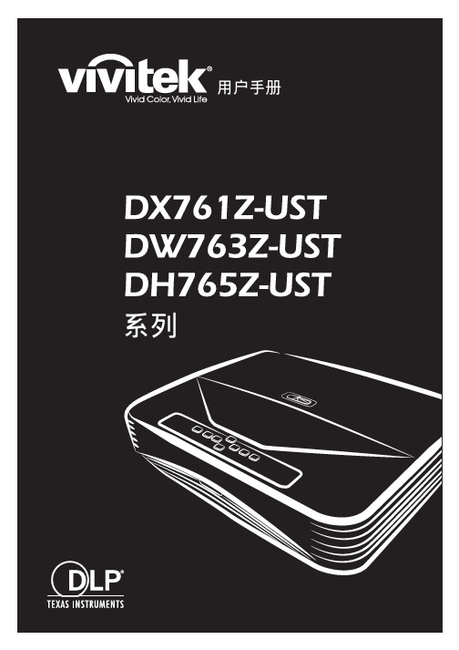
ϡ͗͘ΊրЕFCC 声明此设备经测试证实,符合 FCC 规则第 15 部分关于 B 级数字设备的限制要求。
这些限制的目的是为了在居住区安装时提供合理保护以防止有害干扰。
如果不按照指示进行安装和使用,可能会对无线通信产生有害干扰。
但本公司不保证在特定安装情况下不产生干扰。
如果此设备确实对无线电或电视接收造成有害干扰 (通过关闭后再打开存在疑问的设备来确定),建议用户尝试采取以下一项或多项措施来排除此干扰:• 调整接收天线的方向或位置• 增大设备和接收器之间的间距• 将设备和接收器分别连接到不同的电路插座上• 咨询经销商或经验丰富的专业无线电/电视技术人员以获取帮助。
此设备符合 FCC 规则第 15 部分的要求。
其运行符合下面两个条件:1.此设备不得导致有害干扰。
2.此设备必须承受任何干扰,包括可能导致意外操作的干扰。
安全说明在使用投影机前,请阅读所有这些指导说明,并妥善保管以备日后参考。
1.阅读指导说明在使用设备前,应阅读所有安全和使用指导说明。
2.注意和警告应遵循使用指导说明中的所有注意和警告。
3.清洁在清洁之前,从墙壁电源插座上拔掉投影机电源线插头。
使用湿布擦拭投影机外壳。
请勿使用液体或烟雾清洁剂。
4.附件切勿将投影机置于不稳的推车、架子或桌子上。
产品可能掉落,导致其严重损坏。
将(投影机、附件和选配件)的塑料包装材料放在儿童够不到的地方,否则包装袋可能导致窒息死亡。
对于婴幼儿更要特别注意。
5.通风此投影机配有进气和排气通风孔。
请勿堵塞这些开口或者在开口附近放置任何物品,否则内部可能积聚热量,并导致画面质量下降或投影机损坏。
6.电源确认本机的工作电压与您当地电源的电压相同。
7.维修请勿尝试自行维修此投影机。
委托专业技术人员进行维修。
8.更换部件当需要更换部件时,务必使用制造商指定的更换部件。
未经授权的更换可能导致火灾、触电或其他危险。
9.水汽凝结将投影机从寒冷的地点移到温暖的地点后,切勿立即使用。
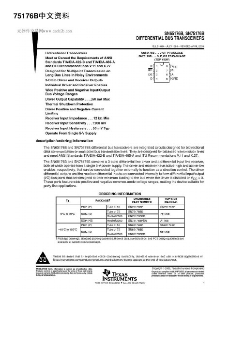
75176B中⽂资料PACKAGING INFORMATION Orderable Device Status(1)PackageType PackageDrawingPins PackageQtyEco Plan(2)Lead/Ball Finish MSL Peak Temp(3)SN65176BD ACTIVE SOIC D875Green(RoHS&no Sb/Br)CU NIPDAU Level-1-260C-UNLIMSN65176BDE4ACTIVE SOIC D875Green(RoHS&no Sb/Br)CU NIPDAU Level-1-260C-UNLIMSN65176BDG4ACTIVE SOIC D875Green(RoHS&no Sb/Br)CU NIPDAU Level-1-260C-UNLIMSN65176BDR ACTIVE SOIC D82500Green(RoHS& no Sb/Br)CU NIPDAU Level-1-260C-UNLIMSN65176BDRE4ACTIVE SOIC D82500Green(RoHS& no Sb/Br)CU NIPDAU Level-1-260C-UNLIMSN65176BDRG4ACTIVE SOIC D82500Green(RoHS& no Sb/Br)CU NIPDAU Level-1-260C-UNLIMSN65176BP ACTIVE PDIP P850Pb-Free (RoHS)CU NIPDAU N/A for Pkg TypeSN65176BPE4ACTIVE PDIP P850Pb-Free (RoHS)CU NIPDAU N/A for Pkg TypeSN75176BD ACTIVE SOIC D875Green(RoHS&no Sb/Br)CU NIPDAU Level-1-260C-UNLIMSN75176BDE4ACTIVE SOIC D875Green(RoHS&no Sb/Br)CU NIPDAU Level-1-260C-UNLIMSN75176BDG4ACTIVE SOIC D875Green(RoHS&no Sb/Br)CU NIPDAU Level-1-260C-UNLIMSN75176BDR ACTIVE SOIC D82500Green(RoHS& no Sb/Br)CU NIPDAU Level-1-260C-UNLIMSN75176BDRE4ACTIVE SOIC D82500Green(RoHS&no Sb/Br)CU NIPDAU Level-1-260C-UNLIMSN75176BDRG4ACTIVE SOIC D82500Green(RoHS&no Sb/Br)CU NIPDAU Level-1-260C-UNLIMSN75176BP ACTIVE PDIP P850Pb-Free(RoHS)CU NIPDAU N/A for Pkg TypeSN75176BPE4ACTIVE PDIP P850Pb-Free(RoHS)CU NIPDAU N/A for Pkg TypeSN75176BPSR ACTIVE SO PS82000Green(RoHS&no Sb/Br)CU NIPDAU Level-1-260C-UNLIMSN75176BPSRG4ACTIVE SO PS82000Green(RoHS&no Sb/Br)CU NIPDAU Level-1-260C-UNLIM(1)The marketing status values are defined as follows:ACTIVE:Product device recommended for new designs.LIFEBUY:TI has announced that the device will be discontinued,and a lifetime-buy period is in effect.NRND:Not recommended for new designs.Device is in production to support existing customers,but TI does not recommend using this part in a new design.PREVIEW:Device has been announced but is not in production.Samples may or may not be available.OBSOLETE:TI has discontinued the production of the device.(2)Eco Plan-The planned eco-friendly classification:Pb-Free(RoHS),Pb-Free(RoHS Exempt),or Green(RoHS&no Sb/Br)-please check /doc/7167b986cc22bcd126ff0c93.html /productcontent for the latest availability information and additional product content details.TBD:The Pb-Free/Green conversion plan has not been defined.Pb-Free(RoHS):TI's terms"Lead-Free"or"Pb-Free"mean semiconductor products that are compatible with the current RoHS requirements for all6substances,including the requirement that lead not exceed0.1%by weight in homogeneous materials.Where designed to be soldered at high temperatures,TI Pb-Free products are suitable for use in specified lead-free processes.Pb-Free(RoHS Exempt):This component has a RoHS exemption for either1)lead-based flip-chip solder bumps used between the die andpackage,or2)lead-based die adhesive used between the die and leadframe.The component is otherwise considered Pb-Free(RoHS compatible)as defined above.Green(RoHS&no Sb/Br):TI defines"Green"to mean Pb-Free(RoHS compatible),and free of Bromine(Br)and Antimony(Sb)based flame retardants(Br or Sb do not exceed0.1%by weight in homogeneous material)(3)MSL,Peak Temp.--The Moisture Sensitivity Level rating according to the JEDEC industry standard classifications,and peak soldertemperature.Important Information and Disclaimer:The information provided on this page represents TI's knowledge and belief as of the date that it is provided.TI bases its knowledge and belief on information provided by third parties,and makes no representation or warranty as to the accuracy of such information.Efforts are underway to better integrate information from third parties.TI has taken and continues to take reasonable steps to provide representative and accurate information but may not have conducted destructive testing or chemical analysis on incoming materials and chemicals.TI and TI suppliers consider certain information to be proprietary,and thus CAS numbers and other limited information may not be available for release.In no event shall TI's liability arising out of such information exceed the total purchase price of the TI part(s)at issue in this document sold by TI to Customer on an annual basis.TAPE AND REEL INFORMATIONDevice Package Pins Site ReelDiameter(mm)ReelWidth(mm)A0(mm)B0(mm)K0(mm)P1(mm)W(mm)Pin1QuadrantSN65176BDR D8FMX33012 6.4 5.2 2.1812Q1 SN75176BDR D8FMX33012 6.4 5.2 2.1812Q1 SN75176BPSR PS8MLA330168.2 6.6 2.51216Q1TAPE AND REEL BOX INFORMATIONDevice Package Pins Site Length(mm)Width(mm)Height(mm)SN65176BDR D8FMX338.1340.520.64SN75176BDR D8FMX338.1340.520.64SN75176BPSR PS8MLA342.9336.628.58。
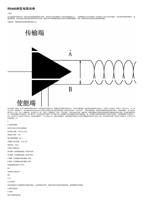
RS485典型电路经典1 概述RS-485建议性标准作为⼀种多点差分数据传输的电⽓规范,现已成为业界应⽤最为⼴泛的标准通信接⼝之⼀,这种通信接⼝允许在简单的⼀对双绞线上进⾏多点双向通信,它所具有的噪声抑制能⼒、数据传输速率、电缆长度及可靠性是其他标准⽆法⽐拟的,因此许多不同领域都采⽤RS-485作为数据传输链路,它是⼀种极为经济并具有相当⾼的噪声抑制、传输速率、传输距离和宽共模范围的通信平台。
RS-485是⼀种在⼯业上作为数据交换的⼿段⽽⼴泛使⽤的串⾏通信⽅式,数据信号采⽤差分传输⽅式,也称作平衡传输,因此具有较强的抗⼲扰能⼒。
它使⽤⼀对双绞线,将其中⼀线定义为A ,另⼀线定义为B 。
通常情况下, RS-485的信号在传送出去之前会先分解成正负对称的两条线路(即我们常说的A 、B 信号线),当到达接收端后,再将信号相减还原成原来的信号。
发送驱动器A 、B 之间的正电平在+2~+6V ,是⼀个逻辑状态;负电平在-2~-6V ,是另⼀个逻辑状态;另有⼀个信号地C ,在RS-485中还有⼀“使能”端。
“使能”端是⽤于控制发送驱动器与传输线的切断与连接。
当“使能”端起作⽤时,发送驱动器处于⾼阻状态,称作“第三态”,即它是有别于逻辑“1”与“0”的第三态。
接收器也与发送端相对的电平逻辑规定,收、发端通过平衡双绞线将AA 与BB 对应相连,当在接收端AB 之间(DT)=(D+) - (D-)有⼤于+200mV 的电平时,输出正逻辑电平,⼩于-200mV 时,输出负逻辑电平。
接收器接收平衡线上的电平范围通常在200mV ⾄6V 之间。
该应⽤现已经被⼴泛⽤于公司批控仪,R7系列产品的485通讯。
Z LF2 主要性能指标DS75176B 芯⽚技术性能指标:供电电压范围:4.75V to 5.25V ;接收输⼊阻抗:12K ;最⼤接收器数量:32个;共模输⼊电压范围:-7V to 12V ;滞回电压:70mV ;关键芯⽚管脚说明:RE 管脚:接收器输出使能(低电平有效)。

LG IG5 3.7KW---2.2KW 380V故障:一般LG的故障由主板引起的有无显示、电位器调不了速、通讯故障等。
在驱动板是好的情况下,主板引起故障的维修方法分析及排除如下:1.无显示故障排除方法无显示一般除底版和开关电源引起故障,主板也经常出现无显示的,办法是先找排插,万用表测量与好的主板对比参数,大多数与3个R271(电阻)的线路扩展找,有很多电阻烧坏的,比如查找R1R3R4R7R812R16R18R19R20R21R22R49等。
主板U2(IC3404)也会引起无显示的,还有震荡器和U10(31AKDS75176BM、MEACDS75176BM)及旁边的电阻损坏也是无显示或者报OC、OU、OH,由于主板一个电阻都有可能一起故障。
2.电位器调不了参数排除方法:先检查光藕PC2.PC3.PC4,如果测量它们的参数相同(不能超过正负5的误差,否则就要换新的),这样在换U9(788J),换上788J后,上电会显示0.00,这个时候,当自己设置好50.00H后,测量输出是否平衡,平衡了在带电机。
如果发现U、V、W、有一项没有输出电压,应该检查光藕PC14、PC15、PC17这三个,它们型号是(5F112A)量下他们参数是与好的主板是不是一样,如果不同就换新的光藕。
大多数换上后输出电压都会正常,有时候还要换U5(33EE7TK、37DL38KLS06、51AJ8HK、57A81RKLS06)换好后这样就会和新的机器运转一样,没有任何瑕疵和不正常的运行声音。
3. 大多主板引起通讯故障报警IOLE,检查电路板是不是有氧化或者被腐蚀的焊脚,电路短路的情况,由于U1(2901)经常会内部线路故障也会报IOLE,其一是更换新的IC,也可以拆坏板应对故障,U1(2901)旁边的电阻与CPU连接线路和CPU周围的电阻是否损坏,以上是LG经常出现的复杂故障。
LG主板大多都通用,我强调在维修时,更换光藕和IC时,看好型号,2.2KW与3.7KW 的IC及光藕有很大区别,在同型号的情况下可替换,反之就是明明换了好的器件也解决不了根本问题。