MS-1441A-0D-0619
- 格式:pdf
- 大小:80.92 KB
- 文档页数:3
HP-1-二甲基聚硅氧烷柱说明:这是最常用的非极性键合固定相,HP-1(二甲基聚硅氧烷),具有极好的热稳定性并且在高温下流失很小,具有低的检测限相似的固定相:DB-1,Rtx-1,SPB-1,CP Sil 5CB,MDN-1,DB-1h.t.,AT-1 007-1恒温/程序升温温度范围:-60至325/350℃,-60至300/320℃0.53内径,-60至260/280℃>2.0mm液膜应用:胺类、烃类、农药、多氯联苯、酚类、含硫化合物HP-1 25m, 0.20mm, 0.33um HP-1 30m, 0.32mm, 0.25umHP-1 15m, 0.25mm, 0.25um HP-1 30m, 0.32mm, 1.0umHP-1 30m, 0.25mm, 0.25um HP-1 60m, 0.32mm, 0.25umHP-1 60m, 0.25mm, 0.25um HP-1 15m, 0.53mm, 1.5umHP-1 30m, 0.53mm, 2.65umHP-35-二苯基-65%-二甲基硅氧烷共聚物说明:HP-35柱是用苯基取代甲基的聚硅氧烷固定相柱。
EPA(美国环保暑)方法8081和UPS(美国药典)G-42中已经指定用此固定相。
HP-35的中极性使其成为分析杀虫剂、除草剂、药物和胺的良好选择。
相似的固定相:DB-35,Rtx-35,SPB-35,AT-35,Sup-herb等温/程序升温温度范围:-40至300/320℃40至280/300℃应用:芳氯物(Aroclors)、胺类、杀虫剂、药品HP-35 15m, 0.25mm, 0.25um HP-35 30m, 0.32mm, 0.15umHP-35 30m, 0.25mm, 0.25um HP-35 30m, 0.32mm, 0.25umHP-35, 60 meter, 0.25mm, 0.25um HP-35 30m, 0.32mm, 0.5umHP-FFAP(键合和改性的交联聚乙二醇)说明:HP-FFAP柱主要特点是能够分析有机酸、游离脂肪酸或用于一些需要定量分析微量酸样品。
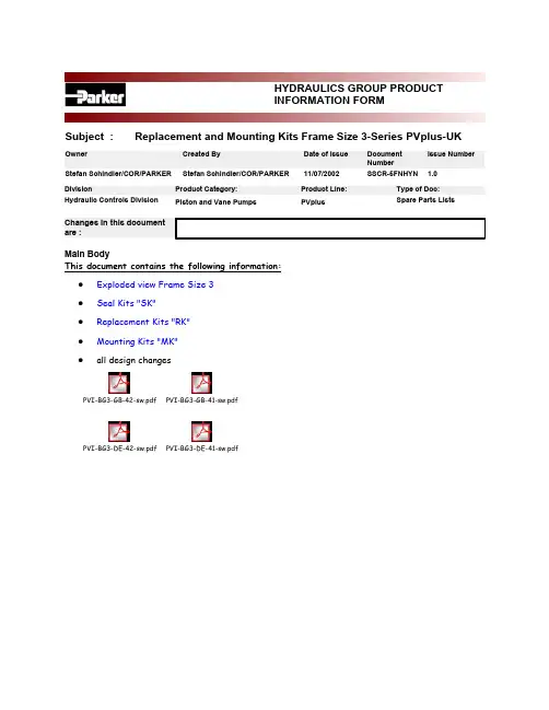
<BR>HYDRAULICS GROUP PRODUCTINFORMATION FORM<BR>Subject : Replacement and Mounting Kits Frame Size 3-Series PVplus-UKIssue Number Owner Created By Date of Issue DocumentNumberStefan Schindler/COR/PARKER Stefan Schindler/COR/PARKER11/07/2002SSCR-5FNHYN 1.0Main BodyThis document contains the following information:Exploded view Frame Size 3zSeal Kits "SK"zReplacement Kits "RK"zMounting Kits "MK"zall design changeszPVI-BG3-GB-42-sw.pdf PVI-BG3-GB-41-sw.pdfPVI-BG3-DE-42-sw.pdf PVI-BG3-DE-41-sw.pdfexploded view, PV series, frame size 3, PV063 - PV092correlation between position numbers and replacement kitspos. No.description page replacement kit 1, 2pump body, end cover--3swash plate, finished6swashplate kit4body seal4seal kit5cradle--6trunnion bearing, HX6trunnion bearing kit7spring washer, servo spring8servo spring kit8servo spring8servo spring kit9connector servo spring6swashplate kit10servo spring plug8servo spring kit11swash plate connector6swashplate kit13tapered / contour sleeve8tapered / contour sleeve 14shaft7shaft unit15piston and slipper, crimped6rotating group, set of pistons 16cylinder block6rotating group17retainer spring, cylinder block6rotating group18pilot cover--20distance washer6rotating group21slipper retainer6rotating group22retainer segment6rotating group23valve plate6valve plate26servo piston sleeve7servo piston sleeve27servo piston7servo piston kit28servo piston cover8displacement adjuster kit 29set screw8displacement limiter kit 30thru drive adaptor10mounting kit, thru drive 31thru drive cover--32air bleed valve8air bleed valve35, 36rotation indicator, name plate--37key7shaft unit38snap ring for shaft7shaft unit39snap ring for bore6rotating group41hexagon socket head cap screw, retainer6rotating group42hexagon socket head cap screw, body6connecting bolt kit43hexagon socket head cap screw, pilot6connecting bolt kit44rivet--45guide pin, servo spring8servo spring kit46locator pin cradle--47locator pin, valve plate6valve plate48locator pin, body6connecting bolt kit50washer, servo piston7servo piston kit51washer, cylinder block6rotating group52washer, shaft7shaft unit53, 54magnet cover for ports, thru drive--55protection plug, drain port--57roller bearing, rear7shaft unit58plug, compensator interface4seal kit59plug, feedback4seal kit60chain link6swashplate kit62roller bearing, front7shaft unit63 - 71o-ring4seal kit72shaft seal4seal kit73self sealing lock nut4, 8seal kit, displacement limiter 75 - 77, 78backup rings, retainer for shaft seal4seal kit79 - 81pipe plug4seal kit82hexagon socket countersunk head cap screw6trunnion bearing kit83hexagon socket head cap screw, cradle--84o-ring4seal kit85hexagon socket head cap screw, thru drive10mounting kit, thru drive 87locator pin, thru drive adaptor10mounting kit, thru drive 90o-ring4seal kit91coupling9mounting kit, couplingSK-seal kitPVBG3PV series, frame size 3, PV063 - PV092N seal option NBRV seal option FPME seal option EPRW seal option NBR with PTFE shaft seal (for water glycole)W seal option NBR with PTFE shaft seal (for water glycole)1threads: metric, port option: BSPP3threads: UNC, port option: UNF7threads: metric, port option: ISO 61498threads: UNC, port option: ISO 614942design series 42includes:41body seal, frame size 3581port plug VSTI-10x1-OR-A3C ISO 6149 NBR seal option NBR 58(1)port plug VSTI-10x1-OR-A3C ISO 6149 FPM seal option FPM 58(1)port plug VSTI-10x1-OR-A3C, ISO 6149 EPR seal option EPR 591port plug M 27 x 2 ISO 6149, NBR seal option NBR 59(1)port plug M 27 x 2 ISO 6149, FPM seal option FPM 59(1)port plug M 27 x 2 ISO 6149, EPR seal option EPR 632o-ring 2-010-N552-90; 6,07 x 1,78seal option NBR 63(2)o-ring 2-010-V747-75; 6,07 x 1,78seal option FPM 63(2)o-ring 2-010-E540-80; 6,07 x 1,78seal option EPR 651o-ring 2-129-N552-90; 39,34 x 2,62seal option NBR 65(1)o-ring 2-129-V747-75; 39,34 x 2,62seal option FPM 65(1)o-ring 2-129-E540-80; 39,34 x 2,62seal option EPR 661o-ring 2-032-N552-90; 47,35 x 1,78seal option NBR 66(1)o-ring 2-032-V747-75; 47,35 x 1,78seal option FPM 66(1)o-ring 2-032-E540-80; 47,35 x 1,78seal option EPR 671o-ring 2-042-N552-90; 82,72 x 1,78seal option NBR 67(1)o-ring 2-042-V747-75; 82,72 x 1,78seal option FPM 67(1)o-ring 2-042-E540-80; 82,72 x 1,78seal option EPR 681o-ring 2-224-N552-90; 44,04 x 3,53seal option NBR 68(1)o-ring 2-224-V747-75; 44,04 x 3,53seal option FPM 68(1)o-ring 2-224-E540-80; 44,04 x 3,53seal option EPR 691o-ring 2-032-N552-90; 47,35 x 1,78seal option NBR 69(1)o-ring 2-032-V747-75; 47,35 x 1,78seal option FPM 69(1)o-ring 2-032-E540-80; 47,35 x 1,78seal option EPR 69(1)o-ring 2-146-N552-90; 66,34 x 2,62seal option NBR 69(1)o-ring 2-146-V747-75; 66,34 x 2,62seal option FPM 69(1)o-ring 2-146-E540-80; 66,34 x 2,62seal option EPR 701o-ring 2-137-N552-90; 52,07 x 2,62seal option NBR 70(1)o-ring 2-137-V747-75; 52,07 x 2,62seal option FPM 70(1)o-ring 2-137-E540-80; 52,07 x 2,62seal option EPR 711o-ring 2-031-N552-90; 44,17 x 1,78seal option NBR 71(1)o-ring 2-031-V747-75; 44,17 x 1,78seal option FPM 71(1)o-ring 2-031-E540-80; 44,17 x 1,78seal option EPR 721shaft seal BABSL 0,5 45 x 62 x 7-NBR seal option NBR 72(1)shaft seal BABSL 0,5 45 x 62 x 7-FPM seal option FPM 72(1)shaft seal PTFE, frame size 3 with EPR o-ring seal option EPR, S 72(1)shaft seal PTFE, frame size 3seal option P, W 731self sealing lock nut M 12 x 1,5; SEAL LOCK751backup ring 8-129-N300-90; 40,16 x 2,18seal option NBR 75(1)backup ring 8-129-V709-90; 40,16 x 2,18seal option FPM 75(1)backup ring 8-129-E652-90; 40,16 x 2,18seal option EPR761backup ring 8-031-N300-90; 44,91 x 1,35seal option NBR 76(1)backup ring 8-031-V709-90; 44,91 x 1,35seal option FPM 76(1)backup ring 8-031-E652-90; 44,91 x 1,35seal option EPR 771backup ring 8-031-N300-90; 44,91 x 1,35seal option NBR 77(1)backup ring 8-031-V709-90; 44,91 x 1,35seal option FPM 77(1)backup ring 8-031-E652-90; 44,91 x 1,35seal option EPR 781J64 x 2 DIN 472, retainer for shaft seal791port plug VSTI R1/2" ED NBR NBR, threads: 1 79(1)port plug VSTI R1/2" ED FPM FPM, threads: 1 79(1)port plug VSTI R1/2" ED EPR EPR, threads: 1 79(1)port plug 10HP50NS-NBR, 7/8-14 UNF NBR, threads: 3 79(1)port plug 10HP50NS-FPM, 7/8-14 UNF FPM, threads: 3 79(1)port plug 10HP50NS-EPR, 7/8-14 UNF EPR, threads: 3 79(1)port plug VSTI-22 x 1,5-OR-A3C ISO 6149 NBR NBR, threads: 7, 8 79(1)port plug VSTI-22 x 1,5-OR-A3C ISO 6149 FPM FPM, threads: 7, 8 79(1)port plug VSTI-22 x 1,5-OR-A3C ISO 6149 EPR EPR, threads: 7, 8 801port plug VSTI R1/4" ED NBR NBR, threads: 1 80(1)port plug VSTI R1/4" ED FPM FPM, threads: 1 80(1)port plug VSTI R1/4" ED EPR EPR, threads: 1 80(1)port plug 4HP50NS-NBR, 7/16-20 UNF NBR, threads: 3 80(1)port plug 4HP50NS-FPM, 7/16-20 UNF FPM, threads: 3 80(1)port plug 4HP50NS-EPR, 7/16-20 UNF EPR, threads: 3 80(1)port plug VSTI-12 x 1,5-OR-A3C ISO 6149 NBR NBR, threads: 7, 8 80(1)port plug VSTI-12 x 1,5-OR-A3C ISO 6149 FPM FPM, threads: 7, 8 80(1)port plug VSTI-12 x 1,5-OR-A3C ISO 6149 EPR EPR, threads: 7, 8 811port plug VSTI R3/4" ED NBR NBR, threads: 1 81(1)port plug VSTI R3/4" ED FPM FPM, threads: 1 81(1)port plug VSTI R3/4" ED EPR EPR, threads: 1 81(1)port plug 12HP50NS-NBR, 1 1/16-12 UNF NBR, threads: 3 81(1)port plug 12HP50NS-FPM, 1 1/16-12 UNF FPM, threads: 3 81(1)port plug 12HP50NS-EPR, 1 1/16-12 UNF EPR, threads: 3 81(1)port plug VSTI-27 x 2-OR-A3C ISO 6149 NBR NBR, threads: 7, 8 81(1)port plug VSTI-27 x 2-OR-A3C ISO 6149 FPM FPM, threads: 7, 8 81(1)port plug VSTI-27 x 2-OR-A3C ISO 6149 EPR EPR, threads: 7, 8 841o-ring 2-036-N552-90; 60,05 x 1,78seal option NBR 84(1)o-ring 2-036-V747-75; 60,05 x 1,78seal option FPM 84(1)o-ring 2-036-E540-80; 60,05 x 1,78seal option EPR 841o-ring 2-041-N552-90; 75,92 x 1,78seal option NBR 84(1)o-ring 2-041-V747-75; 75,92 x 1,78seal option FPM 84(1)o-ring 2-041-E540-80; 75,92 x 1,78seal option EPR 841o-ring 2-042-N552-90; 82,27 x 1,78seal option NBR 84(1)o-ring 2-042-V747-75; 82,27 x 1,78seal option FPM 84(1)o-ring 2-042-E540-80; 82,27 x 1,78seal option EPR 841o-ring 2-044-N552-90; 94,97 x 1,78seal option NBR 84(1)o-ring 2-044-V747-75; 94,97 x 1,78seal option FPM 84(1)o-ring 2-044-E540-80; 94,97 x 1,78seal option EPR 841o-ring 2-048-N552-90; 120,37 x 1,78seal option NBR 84(1)o-ring 2-048-V747-75; 120,37 x 1,78seal option FPM 84(1)o-ring 2-048-E540-80; 120,37 x 1,78seal option EPR 841o-ring 2-163-N552-90; 152,07 x 2,62seal option NBR 84(1)o-ring 2-163-V747-75; 152,07 x 2,62seal option FPM 84(1)o-ring 2-163-E540-80; 152,07 x 2,62seal option EPR 841o-ring 2-164-N552-90; 158,42 x 2,62seal option NBR 84(1)o-ring 2-164-V747-75; 158,42 x 2,62seal option FPM 84(1)o-ring 2-164-E540-80; 158,42 x 2,62seal option EPR 901o-ring 2-012-N552-90; 9,25 x 1,78seal option NBR 90(1)o-ring 2-012-V747-75; 9,25 x 1,78seal option FPM 90(1)o-ring 2-012-E540-80; 9,25 x 1,78seal option EPR 2611o-ring 6-346-N552-90; 9,4 x 2,1seal option NBR 261(1)o-ring 6-346-V747-75; 9,4 x 2,1seal option FPM 261(1)o-ring 6-346-E540-80; 9,4 x 2,1seal option EPRPVBG3PV series, frame size 3, PV063 - PV092VT Verbindungsteile-SatzM metric versionS SAE/UNC version41design series 41 - 42includes:424hexagon socket head cap screw M 16 x 75 DIN 912 12.9threads: M 42(4)hexagon socket head cap screw 5/8" - 11 UNC x 3"threads: S 434hexagon socket head cap screw M 5 x 12 DIN 912 12.9threads: M 43(4)hexagon socket head cap screw Nr. 10 - 24 UNC x 1/2"threads: S 482locating pin 8 M6 x 16 DIN 7 StRK-spare parts kitPVBG3PV series, frame size 3, PV063 - PV092GLE trunnion bearing unit41design series 41 - 42includes:62trunnion bearing HX, frame size 3822hexagon socket countersunk head cap screw M 5 x 10 DIN 7991, c RK-spare parts kitPVBG3PV series, frame size 3, PV063 - PV092ROG rotating group41design series 41 - 42includes:159piston and slipper, crimped161cylinder block with bronce sleeves171retainer spring, cylinder block204distance washer211slipper retainer plate222retainer segment391snap ring for bores, 56 x 2 DIN 472414hexagon socket head cap screw M 6 x 25 DIN 912 12.9 TUF511washer SS 40 x 50 x 2,5 DIN 988521washer SS 45 x 56 x 2 DIN 988RK-spare parts kitPVBG3PV series, frame size 3, PV063 - PV092KOS piston set41design series 41 - 42includes:159piston and slipper, crimpedRK-spare parts kitPVBG3PV series, frame size 3, PV063 - PV092SS valve plateR rotation clockwiseL rotation counter-clockwise41design series 41 - 42includes:231valve plate clockwise rotation, frame size 3rotation R 23(1)valve plate counter-clockwise rotation, frame size 3rotation L 471locating pin 6 M6 x 14 DIN 7 StRK-spare parts kitPVBG3PV series, frame size 3, PV063 - PV092SRS swash plate kit41design series 41 - 42includes:31swash plate, finished, frame size 391connector servo spring, frame size 3111connector swash plate, frame size 3, Keilstop601chain link 548 - 11 DIN 8187PVBG3PV series, frame size 3, PV063 - PV092WP shaft unit, keyedWZ shaft unit, splinedM metric versionS SAE/UNC version41design series 41 - 42includes:141shaft, keyed, metric, frame size 3keyed, metric14(1)shaft, keyed, SAE, frame size 3keyed, SAE14(1)shaft, splined, metric, frame size 3splined, metric 14(1)shaft, splined, SAE, frame size 3splined, SAE371key A12 x 8 x 80 DIN 6885 St keyed, metric37(1)key 11,11 x 11,11 x 80keyed, SAE381snap ring for shaft, 45 x 1,75 DIN 471522washer PS 45 x 56 x 2 DIN 988571roller bearing, RNU - 2206 - ECP,621roller bearing NUP - 2209 - ECP,RK-spare parts kitPV063PV series, frame size 3, PV063PV080PV series, frame size 3, PV080PV092PV series, frame size 3, PV092HE displacement limiter, adjustableN seal option NBRV seal option FPME seal option EPR41design series 41 - 42includes:281port plug M 55 x 2291set screw M 12 x 1,5; displacement 63 cm³/U displacement 063 29(1)set screw M 12 x 1,5; displacement 80 cm³/U displacement 080 29(1)set screw M 12 x 1,5; displacement 92 cm³/U displacement 092 701o-ring 2-137-N552-90; 52,07 x 2,62seal option NBR 70(1)o-ring 2-137-V747-75; 52,07 x 2,62seal option FPM 70(1)o-ring 2-137-E540-80; 52,07 x 2,62seal option EPR 731self sealing lock nut M 12 x 1,5; SEAL LOCKRK-spare parts kitPVBG3PV series, frame size 3, PV063 - PV092SB servo piston sleeveN seal option NBRV seal option FPME seal option EPR42design series 41 - 42includes:261servo piston sleeve, frame size 3661o-ring 2-032-N552-90; 47,35 x 1,78seal option NBR 66(1)o-ring 2-032-V747-75; 47,35 x 1,78seal option FPM 66(1)o-ring 2-032-E540-80; 47,35 x 1,78seal option EPR 711o-ring 2-031-N552-90; 44,17 x 1,78seal option NBR 71(1)o-ring 2-031-V747-75; 44,17 x 1,78seal option FPM 71(1)o-ring 2-031-E540-80; 44,17 x 1,78seal option EPR 761backup ring 8-031-N300-90; 44,91 x 1,35seal option NBR 76(1)backup ring 8-031-V709-90; 44,91 x 1,35seal option FPM 76(1)backup ring 8-031-E652-90; 44,91 x 1,35seal option EPR 771backup ring 8-031-N300-90; 44,91 x 1,35seal option NBR 77(1)backup ring 8-031-V709-90; 44,91 x 1,35seal option FPM 77(1)backup ring 8-031-E652-90; 44,91 x 1,35seal option EPRPVBG3PV series, frame size 3, PV063SKS servo piston kit42design series 42includes:271servo piston frame size 3501washer SS 17 x 24 x 1,5 DIN 988RK-spare parts kitPVBG3PV series, frame size 3, PV063 - PV092RFS servo spring kit41design series 41 - 42includes:71spring washer servo spring frame size 381servo spring frame size 3101servo spring cover frame size 3451roll pin Connex LG 18 x 10032RK-spare parts kitPV000PV series, alle frame sizenEV air bleed valveN seal option NBRV seal option FPME seal option EPR40design series 41 - 42includes:2601body, air bleed valvegehäuse2611o-ring 6-346-N552-90; 9,4 x 2,1seal option NBR 261(1)o-ring 6-346-V747-75; 9,4 x 2,1seal option FPM 261(1)o-ring 6-346-E540-80; 9,4 x 2,1seal option EPR 2621spring, air bleed valve2631ball Ø 6,35, tungston carbide, class G202641roll pin, 2 x 10 DIN 148113RK-spare parts kitPVBG3PV series, frame size 3, PV063 - PV092KH tapered / contour sleeve0tapered sleeve for standard pumpsG contour sleeve for horse power comp. pumps, 11 kWH contour sleeve for horse power comp. pumps, 15 kWK contour sleeve for horse power comp. pumps, 18,5 kWM contour sleeve for horse power comp. pumps, 22 kWS contour sleeve for horse power comp. pumps, 27 kWT contour sleeve for horse power comp. pumps, 37 kWU contour sleeve for horse power comp. pumps, 45 kW41design series 41 - 42includes:131tapered sleeve frame size 313(1)contour sleeve frame size 3, 11 kW horse power code G 13(1)contour sleeve frame size 3, 15 kW horse power code H 13(1)contour sleeve frame size 3, 18,5 kW horse power code K 13(1)contour sleeve frame size 3, 22 kW horse power code M 13(1)contour sleeve frame size 3, 30 kW horse power code S 13(1)contour sleeve frame size 3, 37 kW horse power code Tpos.qty ordering code description remark MK-mounting kit: coupling for thru drive pumpPVBG3PV series, frame size 3, PV063 - PV092K01second pump: metric splined shaft N25 x 1,5 x 15 DIN 5480K02second pump: metric splined shaft N32 x 1,5 x 20 DIN 5480K03second pump: metric splined shaft N40 x 1,5 x 25 DIN 5480K11second pump: SAE splined shaft 9T16/32DP, flat root, side fitK12second pump: SAE splined shaft 11T16/32DP, flat root, side fitK13second pump: SAE splined shaft 13T16/32DP, flat root, side fitK14second pump: SAE splined shaft 15T16/32DP, flat root, side fitK15second pump: SAE splined shaft 14T12/24DP, flat root, side fitK16second pump: SAE splined shaft 17T12/24DP, flat root, side fitK17second pump: SAE splined shaft 13T8/16DP, flat root, side fitK20second pump: metric keyed shaft Ø 12 mmK21second pump: metric keyed shaft Ø 16 mmK22second pump: metric keyed shaft Ø 18 mm41design series 41 - 42includes:911coupling, metric, N40 x 1,5 x 25 DIN 5480shaft K0391(1)coupling, metric, N32 x 1,5 x 20 DIN 5480shaft K02, K20, K21, K2291(1)coupling, metric, N25 x 1,5 x 15 DIN 5480shaft K01 91(1)coupling, SAE, 13T8/16DP, flat root, side fit shaft K17 91(1)coupling, SAE, 17T12/24DP, flat root, side fit shaft K16 91(1)coupling, SAE, 14T12/24DP, flat root, side fit shaft K15 91(1)coupling, SAE, 15T16/32DP, flat root, side fit shaft K14 91(1)coupling, SAE, 13T16/32DP, flat root, side fit shaft K13 91(1)coupling, SAE, 11T16/32DP, flat root, side fit shaft K12 91(1)coupling, SAE, 9T16/32DP, flat root, side fit shaft K11 92(1)adaptor for keyed shaft Ø 18 (also needed: pos 91, shaft K02)shaft K22 92(1)adaptor for keyed shaft Ø 16 (also needed: pos 91, shaft K02)shaft K21 92(1)adaptor for keyed shaft Ø 12 (also needed: pos 91, shaft K02)shaft K20pos.qty ordering codedescriptionremarkMK-mounting kit, adaptor for second pump PVBG3PV series, frame size 3, PV063 - PV092 A second pump: SAE A, Ø 82,55 B second pump: SAE B, Ø 101,6 C second pump: SAE C, Ø 127 D second pump: SAE D, Ø 152,4 G second pump: metric Ø 63 H second pump: metric Ø 80 J second pump: metric Ø 100 K second pump: metric Ø 125 L second pump: metric Ø 160T for pump prepared for thru drive (with cover plate) M metric screws S UNC screws N seal option NBR V seal option FPM E seal option EPR41design series 41 - 42includes:301thru drive adaptor SAE A, Ø 82,55, metric screws pilot: A, screws: M 30(1)thru drive adaptor SAE A, Ø 82,55, UNC screws pilot: A, screws: S 30(1)thru drive adaptor SAE B, Ø 101,6, metric screws pilot: B, screws: M 30(1)thru drive adaptor SAE B, Ø 101,6, UNC screws pilot: B, screws: S 30(1)thru drive adaptor SAE C, Ø 127, metric screws pilot: C, screws: M 30(1)thru drive adaptor SAE C, Ø 127, UNC screws pilot: C, screws: S 30(1)thru drive adaptor SAE D, Ø 152,4, metric screws pilot: D, screws: M 30(1)thru drive adaptor SAE D, Ø 152,4, UNC screws pilot: D, screws: S 30(1)thru drive adaptor: metric Ø 63, metric srews pilot: G, screws: M 30(1)thru drive adaptor: metric Ø 63, UNC srews pilot: G, screws: S 30(1)thru drive adaptor: metric Ø 80, metric srews pilot: H, screws: M 30(1)thru drive adaptor: metric Ø 80, UNC srews pilot: H, screws: S 30(1)thru drive adaptor: metric Ø 100, metric srews pilot: J, screws: M 30(1)thru drive adaptor: metric Ø 100, UNC srews pilot: J, screws: S 30(1)thru drive adaptor: metric Ø 125, metric srews pilot: K, screws: M 30(1)thru drive adaptor: metric Ø 125, UNC srews pilot: K, screws: S 30(1)thru drive adaptor: metric Ø 160, metric srews pilot: L, screws: M 30(1)thru drive adaptor: metric Ø 160, UNC srews pilot: L, screws: S 311cover plate for thru driveoption T691o-ring 2-146-N552-90; 66,34 x 2,62seal option NBR 69(1)o-ring 2-146-V747-75; 66,34 x 2,62seal option FPM 69(1)o-ring 2-146-E540-80; 66,34 x 2,62seal option EPRscrews, washers etc. to fix the second pump are not included in kitsReplacement and mounting kits, PV series, frame size 3, PV063 - PV092file: PVI302-GB-42.xls design series 42pos.qty ordering code description remark 841o-ring 2-036-N552-90; 60,05 x 1,78pilot: G, NBR 84(1)o-ring 2-036-V747-75; 60,05 x 1,78pilot: G, FPM 84(1)o-ring 2-036-E540-80; 60,05 x 1,78pilot: G, EPR 84(1)o-ring 2-041-N552-90; 75,92 x 1,78pilot: H, NBR 84(1)o-ring 2-041-V747-75; 75,92 x 1,78pilot: H, FPM 84(1)o-ring 2-041-E540-80; 75,92 x 1,78pilot: H, EPR841o-ring 2-042-N552-90; 82,27 x 1,78pilot: A, NBR 84(1)o-ring 2-042-V747-75; 82,27 x 1,78pilot: A, FPM 84(1)o-ring 2-042-E540-80; 82,27 x 1,78pilot: A, EPR84(1)o-ring 2-044-N552-90; 94,97 x 1,78pilot: B, J, NBR 84(1)o-ring 2-044-V747-75; 94,97 x 1,78pilot: B, J, FPM 84(1)o-ring 2-044-E540-80; 94,97 x 1,78pilot: B, J, EPR 84(1)o-ring 2-048-N552-90; 120,37 x 1,78pilot: C, K, NBR 84(1)o-ring 2-048-V747-75; 120,37 x 1,78pilot: C, K, FPM 84(1)o-ring 2-048-E540-80; 120,37 x 1,78pilot: C, K, EPR 84(1)o-ring 2-163-N552-90; 152,07 x 2,62pilot: D, NBR84(1)o-ring 2-163-V747-75; 152,07 x 2,62pilot: D, FPM84(1)o-ring 2-163-E540-80; 152,07 x 2,62pilot: D, EPR84(1)o-ring 2-164-N552-90; 158,42 x 2,62pilot: L, NBR84(1)o-ring 2-164-V747-75; 158,42 x 2,62pilot: L, FPM84(1)o-ring 2-164-E540-80; 158,42 x 2,62pilot: L, EPR854hexagon socket head cap screw M 12 x 35 DIN 912 12.9screws: M85(4)hexagon socket head cap screw 1/2" - 13 UNC x 1 1/4" 12.9screws: S872locating pin 8 M6 x 16 DIN 7not for option T 972hexagon socket head cap screw M 10 x 20 DIN 912 12.9option T, screws: M 97(2)hexagon socket head cap screw 3/8" - 16 UNC x 3/4" 12.9option T, screws: Spage 11 of 1123.06.2003。

旋转编码器2012年11月带安装式定子联轴器的旋转编码器分离式联轴器的旋转编码器本样本是以前样本的替代版,所有以前版本均不再有效。
订购海德汉公司的产品仅以订购时有效的样本为准。
产品遵循的标准(ISO,EN等),请见样本中的标注。
海德汉公司的旋转编码器是测量旋转运动、角速度的传感器,也可与机械测量设备一起使用,例如丝杠,测量直线运动。
应用领域包括电机、机床、印刷机、木工机器、纺织机器、机器人和运送设备以及各种测量,测试和检验设备。
高质量正弦增量信号可进行高倍率细分,用于数字速度控制。
电子手轮2目录选型指南标准用途的旋转编码器供电电源3.6至5.25 V DC2) 内部2倍频细分后最大至10 000个信号周期数3) 内部5/10倍频细分后最大至36 000个信号周期(如果需要更高细分倍数,可提供)42634 ERN 480000至5 000线405选型指南标准用途的旋转编码器内部2倍频细分后最大周期数为10 0002) 内部5/10倍频细分后最大至36 000个信号周期(如果需要更高细分倍数,可提供)642 50 54 7选型指南电机旋转编码器内部2倍频细分后8 192个信号周期2) 内部5/10/20/25倍频细分后37 500个信号周期8参见产品信息910供电电源3.6至5.25 V DC2)内部2倍频细分后最大至10 000个信号周期数3)内部2倍频细分后8 192个信号周期4)根据用户要求,可提供盲孔轴版选型指南特殊用途的旋转编码器40请见产品概要:应用于电梯行业的旋转编码器请见产品概要:11测量原理测量基准测量方法海德汉公司的光学扫描型光栅尺或编码器的测量基准都是周期刻线-光栅。
这些光栅刻在玻璃或钢材基体上。
这些精密光栅通过多种光刻工艺制造。
光栅的制造方式有:•在玻璃上镀硬铬线•在镀金钢带上蚀刻线条,或者•在玻璃或钢材基体上蚀刻三维结构图案。
海德汉公司开发的光刻工艺生产的栅距典型值为50 µm至4 µm。
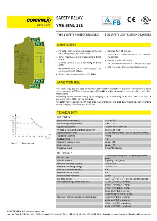
DATA SHEETSAFETY RELAYYRB-4EML-31SFOR SAFETY LIGHT CURTAINS/BARRIERSTYPE 4 SAFETY PROTECTION DEVICETECHNICAL DATAAPPLICATION AREAThe safety relay can be used to monitor electrosensitive protective equipment with monitored active switching output (OSSD) in accordance with EN 61496 as well as emergency stop and safety door locking mechanisms.Depending on the external wiring, up to category 4, PL e according to EN ISO 13849-1 or SILCL 3 according to EN 62061 can be achieved.The safety relay is equipped with three enabling current paths that drop out without delay corresponding to stop category 0 according to EN 60204-1.–For safety light curtains and access control bar-riers, emergency stop, door switch –Safety Integrity Level (SIL) 3 according to IEC/EN 61508 –Claimed Level (SIL CL) 3 according to IEC/EN 62061 –Performance Level (PL) e and category 4 ac-cording to EN/ISO 13849-1 –Safety category 4 according to EN 954-1–Certified TÜV , CE and UL–Output: 3 N.O. safety contacts / 1 N.C. monitor-ing contact –Manual or automatic restart–LED indicator for channel 1, 2 and power supply –22.5 mm wide, DIN-rail-mountable housingMAIN FEATURESFigure 1 Derating curveTECHNICAL DATADATA SHEETYRB-4EML-S41_E.indd / page 1-2 / rev. 1 / 27.01.16 / MDMDATA SHEETPART REFERENCESTRUCTURE AND OPERATION (BLOCK DIAGRAM)WARNING: Risk of electric shockDuring operation, parts of electrical switching devices carry hazardous voltages.Before working on the switching device, disconnect the power.Please observe the safety regulations of electrical engineering and industrial safety and liability associations!Disregarding these safety regulations may result in death, serious personal injury or damage to equipment.Startup, mounting, modifications, and upgrades should only be carried out by a skilled electrical engineer!WARNING: Risk of automatic machine restart!For emergency stop applications, the machine must be prevented from restarting automatically by a higher-level controlsystem.Protective covers must not be removed when operating electrical switching devices.WARNING: Danger due to faulty devices!The devices may be damaged following an error and correct operation can no longer be ensured.In the event of an error, replace the device immediately.Repairs to the device, especially if the housing must be opened, may only be carried out by the manufacturer or autho-rized persons. Otherwise the warranty is invalidated.NOTE: Risk of damage to equipment due to incorrect installation!For reliable operation, the safety relay must be installed in housing protected from dust and humidity (IP 54).Carry out wiring according to the application. Refer to the “Application examples” section for this.NOTE: Risk of damage to equipment due to noise emissionsWhen operating relay modules the operator must meet the requirements for noise emission for electrical and electronic equipment (EN 61000-6-4) on the contact side and, if required, take appropriate measures.For the diagnostic description, please refer to the application manual for PSR safety relays.SAFETY NOTESFigure 2 Block diagramDATA SHEETKEYTwo-channel light grid monitoring (cross-circuit detection via light grid)– Manual activation– Automatic activation with jumper at S33-S35– Suitable up to category 4, PL e (EN ISO 13849-1), SILCL 3 (EN 62061)APPLICATION EXAMPLEFigure 4 Two-channel light grid monitoringOPERATING AND INDICATION ELEMENTSFigure 3 YRB-4EML-31SYRB-4EML-31SYRB-4EML-S41_E.indd / page 3-4 / rev. 0 / 19.11.15 / MDMDATA SHEETAPPLICATION EXAMPLETwo-channel emergency stop circuit without cross-circuit detection, with monitored reset button– Manual activation– Automatic activation with jumper at S33-S35– Suitable up to category 3, PL d (EN ISO 13849-1), SILCL 2 (EN 62061)Single-channel emergency stop monitoring– Manual activation– Automatic activation with jumper at S33-S35– Suitable up to category 1, PL c (EN ISO 13849-1), SILCL 1 (EN 62061)Two-channel safety door monitoring without cross-circuit detection, with monitored reset button– Manual activation– Automatic activation with jumper at S33-S35– Suitable up to category 3, PL d (EN ISO 13849-1), SILCL 2 (EN 62061)Figure 5 Two-channel emergency stop circuit without cross-circuit detectionFigure 6 Single-channel emergency stop circuit with monitored reset buttonFigure 7 Two-channel safety door monitoring without cross-circuit detectionYRB-4EML-31SYRB-4EML-31SYRB-4EML-31SYRB-4EML-S41_E.indd / page 5 / rev. 0 / 19.11.15 / MDM。
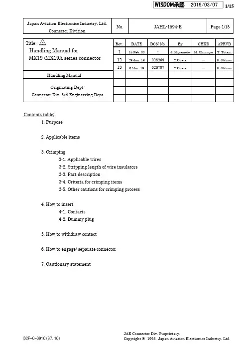
Japan Aviation Electronics Industry,Ltd.Connector DivisionNo.JAHL-1594-E Page 1/15Title:Handling Manual forMX19/MX19A series connectorRev.DATEDCN No.ByCHKDAPRVD115Feb.00-J.Miyamoto M.ShinmyoT.Totani1229Jan.19028264Y.Obata ―H.Obikane 136Mar.19028707Y.Obata―H.ObikaneHandling Manual Originating Dept.:Connector Div.3rd Engineering Dept.Contents table;1.Purpose2.Applicable items3.Crimping3-1.Applicable wires3-2.Stripping length of wire insulators 3-3.Part description3-4.Criteria for crimping items3-5.Other cautions for crimping process4.How to insert4-1.Contacts 4-2.Dummy plug5.How to withdraw contact6.How to engage/separate connector7.Cautionary statement△72019/03/071.PurposeThis document provides the handling on MX19/MX19A series connectors.2.Applicable items2.1HousingTable2-1MX19/MX19A Connector HousingTerminals No.Type Product Name Body Color Matseal color2 (Fig.2-1)Pin housingMX19002P51BlackBrown(Fig.2-4)MX19002P52GraySocket housingMX19002S51BlackMX19002S52Gray4(Fig.2-2)Pin housingMX19004P51BlackMX19004P52GraySocket housingMX19004S51BlackMX19004S52Gray2(Fig.2-1)Pin housing MX19A002P53GrayGreen(Fig.2-4)Socket housingMX19A002S53GrayMX19A002S54Black3(Fig.2-3)Socket housingMX19A003S51BlackGreen(Fig.2-4)MX19A003S52Light BlueMX19A003S53Gray2.2Contacts and Dummy plugTable2-2MX19Contacts and Dummy plugType Product Name NOTEPin contact MX19P10K451Sn platting Fig.2-5Socket contact MX19S10K451Sn platting Fig.2-6Dummy plug MX19000XD1Color:white Fig.2-7Pin housing Socket housing Pin housing Socket housing Fig.2-1MX192-terminals type Fig.2-2MX194-terminals typeMX19A003S51MX19A003S52(Key type A)MX19A003S53(Key type B)Fig.2-3MX193-terminals type△2△3△4△7△8△9△11△7△9911Fig.2-4Matseal color confirmationFig.2-5Pin contact Fig.2-6Socket contact Fig.2-7Dummy plug3.CrimpingJAE’s applicator is described on the following table.Table3-1JAE Crimping ApplicatorType Automatic applicator Semi-automatic applicatorProduct name350-MX19-3B350-MX19-23.1Applicable wire typeTable3-2Applicable wire for MX19/MX19A connector Wire type Conductor construction (No./Shape or size)Calc.Conductor of cross-section [mm 2]Wire insulator [mm]ApplicablehousingCAVS 0.3mm 27/Round compressed0.3717φ1.4 ~1.5MX19002P5*MX19002S5*MX19004P5*MX19004S5*MX19A002P5*MX19A002S5*MX19A003S5*CPTL 227 / φ0.13 0.3717φ1.57 (Ref.) CAVS 0.5mm 27/Round compressed0.563φ1.6 ~1.7AVSS 0.3mm 27 / φ0.260.3717φ1.4 ~1.5AVSS 0.5mm 27 / φ0.13 0.563φ1.6 ~1.7FLRY-B 0.5mm 216 / φ0.196 0.4536φ1.4 ~1.7FLRY-A 0.35mm 27 / φ0.245 0.33φ1.2 ~1.3MX19A002P5*MX19A002S5*MX19A003S5*FLRY-B 0.35mm 212 / φ0.1910.3402φ1.2 ~1.4Check the matseal color from a housing back side.△7△9△7△9△7△9△7△9△5△5△7△8△9△103.2Stripping length of wire insulatorsCheck the stripping length of wire insulators (refer to Fig.3-2.)On the wire treatment,must check the damaged insulator,damaged,missing and/or disordered conductor (refer to Fig.3-1.)Fig.3-1Defective wire treatment for crimplingFig.3-2Stripping length for MX19contact crimping3.3Part description 3.3.1Pin contactFig.3-3Part description of pin contactContact Length A [mm]MX19P10K4512~2.5mmMX19S10K451M19P09K3F2M19S09K3F2FailFail Fail Fail△73.3.2Socket contactFig.3-4Part description of Socket contact3.4Criteria for crimping items "Properly crimped contact"is as follows:1.Meet the crimp height shown in Table 3-3.2.The bell-mouth (no crimping on conductor)is attached.3.The tip of conductor sticks out 0.5mm (or less)from the conductor barrel.4.All conductor of wire is within the conductor barrel.5.Any wire insulator is NOT crimped into the conductor barrel.6.No cracks and/or burrs etc.is in crimping area.Table3-3Appropriate crimp heightWire type Crimp height [mm]Crimp wide [mm](Ref.)Crimp height of wire insulator [mm]CAVS0.3mm 20.73~0.831.48~1.54 1.6~1.7CPTL 220.73~0.83 1.48~1.54 1.7~1.9CAVS 0.5mm 20.75~0.85 1.52~1.58 1.7~1.9AVSS 0.3mm 20.73~0.83 1.48~1.54 1.55AVSS 0.5mm 20.75~0.85 1.52~1.58 1.7~1.9FLRY-A 0.35mm 20.73~0.83 1.48~1.54 1.55FLRY-B 0.35mm 20.73~0.83 1.48~1.54 1.4FLRY-B 0.5mm 20.75~0.851.52~1.581.6NOTE 1:Crimp height dimension is formed by JAE's applicator.NOTE 2:Crimp width/height and crimp height of wire insulators are reference valuesonly.△3△4△7△10△4△53.4Criteria for crimping itemsIf a crimped MX19contact has any following defective item,the crimping work is failure.DON’T usethe failure crimping contact.4.Contact and dummy plug insertion 4.1Contact insertion1.Visual inspection,the connector has no breakage,deformation,discoloration,and/or damage etc.2.Aligned the axis and direction between a contact and a cavity.3.Handling the wire of the near position of contact for not to be occurred bending.4.Contact insertion is completely done until the contact locking part sounded.(Check the terminal insertion by pulling the wire with little force.)NOTE:If the contactinsertion is tight or incapable,DON’T force to insert,check the direction of contact.Tight (or incapable)insertion will cause a contact deformation,crack and/or disconnection.Fig.4-1Contact insertionFig.4-2Example of contact deformation by wrong contact insertionRight wayWrongway△2△34.2Dummy plug insertion1.Check by visual inspection,the connector has no breakage,deformation,discoloration,and/or damage etc.2.Aligned the axis between a dummy plug and acavity.3.Inserting a dummy pluginto cavity,insertion is the end-face of dummy-plug by connector's.Acceptance Criteria:Base on the housing end-face,Dummy plug’s end-face is within 0+0.5/-0.5mm.NOTE:DON’T apply unnecessary force toon inserting dummy plug.Fig.4-3Dummy plug insertiona.Absence insertionb.over insertionFig.4-4Failure dummy plug insertion△45.Contact withdraw 1.Visual inspection,the connector has no breakage,deformation,discoloration,and/or damage etc.2.Push lightly the wire with crimpling contact.3.Insert a withdrawing tool into a tool cavity,as following Fig.6-2and Fig.6-3.4.When the toe of withdrawing tool met the molding lance,release contact locking.5.Withdraw the wire on straight axis.Fig.5-1Pin contact withdrawFig.5-2Socket contact withdrawNOTE:Suitable dimension for withdrawing tool (JAE’s withdrawing tool is “ET-MX19.”)NOTE:DON’T snag a contact on grommet by forcedly withdrawing.NOTE:The limitation frequency for withdrawing at one cavity is 3times.If you find any damage anddeformation,DON’T use it,change to the new one.NOTE:DON’T apply unnecessary force on withdrawing.NOTE:Withdrawing tool insertion is only a “tool cavity,”never inserting the contactcavity.±0.03△26.How to engage connector6.1Engaging1.Check the contact insertion.2.Check by visual inspection,the connector has no breakage,deformation,discoloration,and/or damage etc.in contacts and housing.3.Aligned the direction with the engagement aperture.4.Insert the connector into the housing until the lock parts sounded.NOTE:DON’T apply unnecessary force to connector on inserting/separating connector.NOTE:If housings insertion is tight or incapable,DON’T force to insert,check the direction of contact.Tight (or incapable)insertion will cause a connector deformation,crack and/or disconnection.Fig.6-1Connectorinsertion6.2Connector separation methodHold socket housing,and pull out the connector straightly;1:Depressing the lock arm of socket housing.2:Releasing the engagement lock.NOTE:On separating the connector,DON’T pulling only wires and prying the connector.NOTE:In case of incapable of separation,DON’T force it to pull out.Check the engagement lock is released.NOTE:DON’T apply unnecessary force to connector on inserting/separating connector.Fig.6-2Connectorseparation7.Cautionary Statements7.1Sealing rubber set Care must be taken when handling MX19and MX19A series connector body to avoid rotation of the seal.Once the seal has been rotated,twisted,turned or displaced,JAE cannot take liability for loss or displacement of seal in any post-JAE operations,and can offer noguaranteeon the performance of theconnector.”NOTE.Extreme care is tobeexercised when using rubber,latex or rubber coat fabric gloves.These gloves are designed to havehigh tactileadhesion &will cause displacement of thesealifmis-handled.(a)Rotated (b)Twisted /Turned(c)DisplacedFig.7-1Examples for failure state of seal ring△12△137.Cautionary Statements 7.2Caution。
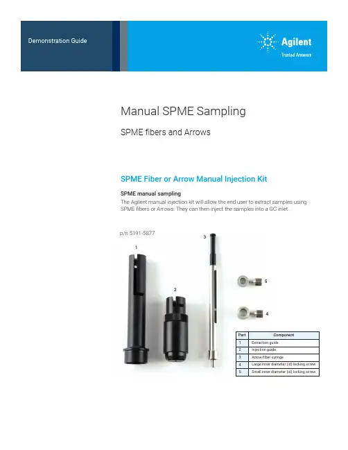
12345SPME Fiber or Arrow Manual Injection KitSPME manual samplingThe Agilent manual injection kit will allow the end user to extract samples using SPME fibers or Arrows. They can then inject the samples into a GC inlet.Manual SPME SamplingSPME fibers and Arrowsp/n 5191-58772PAL3 alignment ring (gray) for split/splitless (S/SL) inletManual injectionManual injection guidePAL3 alignment ring (Gray) for S/SL inlet (G7371-67001)The manual injection guide sits on thealignment ring for manual sample injection.3Methodology—manual samplingInstalling a PDMS SPME (100 μm) Arrow into the manual syringeLoosen the cap at the base of the syringe and remove it.Depress the black plunger completely.Screw the hub of an SPME fiber/Arrow into the bottom of the plunger at the end of thesyringe bodyRetract the black plunger and slide the cap over the SPME fiber/Arrow and tighten itonto the syringe.4The extraction guide has two positions where the syringe can be installed.The upper position is used for headspace extraction.The lower position is used for immersion extraction.Incorrect and correct position of the lower locking screw.Do not tighten the screw against the black plunger or you will not be able to move the SPME fiber/Arrow intoposition for sampling.Setting the locking screwsLarge inner diameter (id) locking screwSmall inner diameter (id) locking screwSlide the locking screws onto the syringe from the plunger side (the right side as shown above).• Install the large id locking screw onto the silver body of the syringe.• Install the small id locking screw onto the wider portion of the black plunger.•Tighten the locking screws until finger-tight. Do not overtighten, as they will be adjusted in later steps.5• Raise the syringe plunger to the fully extended position and insert the syringe and lower locking screw into the upper position of the extraction guide.•Lock the syringe into place by rotating it until the locking screw is positioned in the notch.• Adjust the syringe so that the SPME fiber/Arrow is protruding ~1 cm beyond the inner base of the extraction guide (A).• Tighten the lower locking screw securely.•The tip of the SPME fiber/Arrow will be recessed at least 1 mm in from the end ofthe extraction guide (B).A BSetting the locking screws for septum penetration depthPlace the extraction guide (with syringe in place) on a headspace sampling vial and loosen the upper locking screw.Adjust the SPME fiber/Arrow to the desired exposure depth by moving the black plunger.Choose a depth that ensures that the SPME fiber/Arrow will be in the gas phase.Once the SPME fiber/Arrow is at the proper depth, hold the plunger in place and slide the upper locking screw until it is flush against the top of the silver syringe body. Then tighten the upper locking screw securely.Setting the exposure depth for headspace extraction6Fine depth adjustment for direct immersion extractionAdjusting the injector penetration depthInsert the syringe into the lower position of the extraction guide.1. Manual SPME injection guide2. PAL3 alignment ring (gray) forS/SL inlet (G7371-67001)• Carefully insert the syringe into the injection guide.• Use caution to avoid damaging the SPME fiber/Arrow when threading it through the hole in the base of the injection guide.•Lock the syringe into place by rotating it until the locking screw is positioned in the notch.Penetrate a vial and fully expose the SPME fiber/Arrow within the vial.Adjust the lower locking screw and upper locking screw to obtain the desired exposure depth (to ensureimmersion in the sample liquid).127Setting injector penetration depthWith the appropriate GC-specific adaptor cup on the end of the injection guide, measure the distance from the tip of the SPME fiber/Arrow to the groove inside the adaptor cup.Adjust the desorption depth by screwing the body of the injection guide up or down (maximum depth = 67 mm).Twist the locking ring down until it locks on the body of the injection guide./chemDE.3985648148This information is subject to change without notice.© Agilent Technologies, Inc. 2020 Printed in the USA, March 6, 2020 5994-1732ENInjection onto the GC inletRemove the adapter cup from the injection guide.The adapter cup is placed onto the GC inlet to guide the manual injection.Push the plunger down until the top locking screw is resting on the body of the syringe.The sample is then injected.。
宏基acer全新列笔记本主板编号(工厂料号)与机型Acer Aspire SeriesAspire 1410 Series (1414WLCi), Model ZL1Aspire 1640 Series (1641LCi, 1641WLMi, 1642WLMi, 1644WLMi), Model ZL8Aspire 1640Z Series (1641ZWLMi, 1642ZWLMi, 1644ZWLMi), Model ZL9Aspire 1650 Series (1652WLMi, 1654WLMi), Model ZL8Aspire 1650Z Series (1652ZWLMi, 1654ZWLMi), Model ZL9Aspire 1670 Series (1672WLCi), Model LW80Aspire 1680 Series (1681LCi, 1681LMi, 1681WLCi, 1681WLMi, 1682WLMi, 1681WFLM, 1681WFLCi, 1681WNLC, 1681WNLM, 1684WLMi, 1685WLMi), Model ZL1Aspire 1690 Series (1690WLMi, 1690LCi, 1690WLCi, 1691WLCi, 1691WLMi, 1692WLMi, 1694WLMi), Model ZL2/ZL3Aspire 1800 Series (1801WSCi, 1801WSM, 1801WSMi, 1802WSM, 1802WSMi), Model CQ60 Aspire 2000 Series (2001LCi, 2002LCi, 2002LMi, 2003LMi, 2001WLC, 2001WLM, 2003WLM, 2001WLCi, 2001WLMi, 2002WLCi, 2002WLMi, 2003WLMi), Model CL32/DCL32Aspire 2010 Series (2012WLCi, 2012WLMi), Model FL32/DFL32Aspire 2020 Series (2023WLMi, 2025WLMi), Model FL32/DFL32Aspire 3000 Series (3002LC, 3002LCi, 3002LM, 3002LMi, 3002NLC, 3002NLCi, 3002NWLCi, 3002WLCi, 3002WLMi, 3003WCi, 3003WLCi, 3003WLMi, 3004WLCi, 3004WLMi), Model ZL5Aspire 3020 Series (3020LMi, 3020WLMi, 3021WLMi, 3022LMi, 3022WLM, 3022WLMi, 3023LMi, 3023WLM, 3023WLMi, 3025WLM, 3025WLMi), Model MS2171Aspire 3030 Series (3032WLM, 3032WLMi, 3034WXMi), Model FL52Aspire 3040 Series (3042LMi, 3044WLMi, 3045WLMi), Model MS2171Aspire 3050 Series (3050-1142, 3050-1494, 3050-1535, 3050-1547, 3050-1579, 3050-1594, 3050-1710, 3050-1787, 3050-1800, 3050-1854, 3050-1894, 3050-1908, 3050-1946), Model ZR3 Aspire 3100 Series (3102NWLMi), Model BL51/HCW50/51Aspire 3500 Series (3502LCi, 3502NLCi, 3502NLCi, 3503LCi, 3503WLCi), Model ZL6Aspire 3510 Series, Model ZL3Aspire 3600 Series (3603WXCi), Model FL50/EFL50Aspire 3610 Series (3612LCi, 3613LCi, 3613WLCi, 3613WLMi), Model MS2177Aspire 3620 Series (3623NWXMi, 3623WLCi, 3623WLMi, 3623WXCi, 3623WXCi, 3624WXCi, 3624WXMi), Model MS2180Aspire 3630 Series (3634LMi, 3634WLMi), Model ZL6Aspire 3640 Series (AS3641WXMi), Model MS2180Aspire 3650 Series (AS3651WLMi), Model BL52Aspire 3660 Series (3660-2073, 3660-2209, 3660-2248, 3660-2314, 3660-2438, 3660-2501, 3660-2552, 3660-2662, 3660-2713, 3660-2728, 3661WLMi), Model ZB3Aspire 3670 Series (3670WXMi), Model MS2180Aspire 3680 Series (3680-2108, 3680-2233, 3680-2301, 3680-2513, 3680-2626, 3680-2974), Model ZR1 ONLY, not for ZB2Aspire 3690 Series (3690-2009, 3690-2032, 3690-2070, 3690-2083, 3690-2087, 3690-2119,3690-2138, 3690-2139, 3690-2150, 3690-2173, 3690-2208, 3690-2268, 3690-2306, 3690-2363, 3690-2408, 3690-2430, 3690-2436, 3690-2468, 3690-2481, 3690-2485, 3690-2510, 3690-2513, 3690-2518, 3690-2522, 3690-2524, 3690-2612, 3690-2639, 3690-2654, 3690-2662, 3690-2693, 3690-2711, 3690-2813, 3690-2819, 3690-2848, 3690-2861, 3690-2862, 3690-2875, 3690-2906, 3690-2922, 3690-2949, 3690-2955, 3690-2983), Model BL50, HBL50/HBL51Aspire 4220 Series, Model Z03Aspire 4220G Series, Model Z03Aspire 4310 Series (4310NWXCi, 4310-300508Mi, 4310-300512Mi, 4310-400508Mi, 4310-400512Mi), Model MS2219Aspire 4320 Series (4320-050507Mi, 4320-050512Mi, 4320-100508, 4320-101G12, 4320-300512Mi), Model Z01Aspire 4520 Series (4520-2A0508, 4520-300512, 4520-301G12, 4520-400512Mi, 4520-5A0508, 4520-5582, 4520-5803, 4520NWXMi), Model Z03Aspire 4520G Series (4520G-100108, 4520G-301G16, 4520G-401G16Mi, 4520G-404G16Mi), Model Z03Aspire 4710 Series (4710NWXMi, 4710-2013, 4710-101G12, 4710-101G16, 4710-3A0512, 4710-4A1G12), Model MS2219Aspire 4710Z Series (4710Z NWXMi, 4710Z WXMi, 4710Z-3A0508, 4710Z-3A0512Mi), Model MS2219Aspire 4720 Series (4720-2013, 4720-4825, 4720-1A1G12, 4720-1A0512, 4720-301G16, 4720-3A2G12Mi), Model Z01Aspire 4720G Series (4720G-3A1G16Mi, 4720G-302G16Mi), Model Z01Aspire 4720Z Series (4720ZNWXMi, 4720Z-1A1G08Mi, 4720Z-2A0516Mi), Model Z01Aspire 4920 Series (4920WXMi, 4920-301G16), Model MS2219Aspire 4920G Series (4920G-101G16, 4920G-301G16N, 4920G-302G16, 4920G-3A2G25Mn), Model MS2219Aspire 5020 Series (5020LCi, 5020LMi, 5021LCi, 5021LMi, 5021NWLCi, 5021WLCi, 5021WLM, 5021WLMi, 5022NWLMi, 5022WLM, 5022WLMi, 5023WLMi, 5024LMi, 5024WLCi), Model MS2171Aspire 5030 Series (5030WXMi, 5032WLM, 5032WLMi, 5032WXMi, 5033WLC, 5033WLCi, 5033WLM, 5033WLMi, 5033WXMi, 5034WLM, 5034WLMi, 5034WXMi), Model FL52Aspire 5040 Series (5043WLMi, 5044WLMi), Model MS2171Aspire 5050 Series (5050-3242, 5050-3465, 5050-3564, 5050-5172, 5050-5374, 5050-5410, 5050-5554, 5050-5555, 5050-5574, 5050-5827, 5050-5951), Model ZR3Aspire 5100 Series (5101A WLMi, 5102WLMi), Model BL51/HCW50/51Aspire 5110 Series (5112WLMi), Model BL51/HCW50/51Aspire 5220 Series (5220-201G16Mi, 5220-050508Mi ,5220-050512), Model ICW50Aspire 5220G Series (5220G-201G12Mi, 5220G-201G16Mi), Model ICW50Aspire 5310 Series (5310-2153, 5310-301G08Mi, 5310-301G12Mi), Model JDW50Aspire 5310G Series, Model JDW50Aspire 5320 Series (5320-2180, 5320-051G12Mi, 5320-101G12Mi), Model ICL50Aspire 5320G Series, Model ICL50Aspire 5500 Series (5502ZWXCi, 5502ZWXMi), Model FL50/EFL50Aspire 5500Z Series (5502ZWXCi, 5502ZWXMi), Model FL50/EFL50Aspire 5510 Series (5512WLMi, 5513EWLM, 5513EWLMi, 5513WLMi, 5514WLMi), Model ZL7Aspire 5520 Series (5520-5147, 5520-5334, 5520-5912, 5520-5A2G16), Model ICW50Aspire 5520G Series (5520G-402G16Mi, 5520G-403G25, 5520G-604G25Bi, 5520G-7A2G16Mi), Model ICW50Aspire 5540 Series (5542NWXC, 5542NWXCi, 5542NWXM, 5542NWXMi, 5542WXC, 5542WXCi, 5542WXM, 5542WXMi, 5543NWXCi, 5543NWXMi, 5543WXCi, 5543WXMi), Model MS2180Aspire 5550 Series (5550NWMi, 5550WXMi, 5551NWXMi, 5551WXMi, 5552NWXCi, 5552NWXMi, 5552WXCi, 5552WXMi, 5553NWXCi, 5553NWXMi, 5553WXMi), Model MS2180Aspire 5560 Series (5560A WLMi, 5560A WXMi, 5560WXCi, 5560WXMi, 5561AWLMi, 5561A WXMi, 5561WXMi, 5562A WXMi, 5563NWLMi, 5563NWXMi, 5563WLMi, 5563WXMi, 5564WXMi), Model MS2180Aspire 5570 Series (5570-4174, 5570-4285, 5570-4581, 5570-4765), Model ZR1Aspire 5570Z Series (5570-2016, 5570-2018, 5570-2087, 5570-2094, 5570-2118, 5570-2163, 5570-2164, 5570-2197, 5570-2214, 5570-2219, 5570-2223, 5570-2364, 5570-2405, 5570-2429, 5570-2493, 5570-2504, 5570-2565, 5570-2569, 5570-2609, 5570-2624, 5570-2656, 5570-2731, 5570-2746, 5570-2751, 5570-2758, 5570-2773, 5570-2792, 5570-2846, 5570-2852, 5570-2935, 5570-2937, 5570-2941, 5570-2947, 5570-2948, 5570-2960, 5570-2961, 5570-2985, 5570-2998), Model ZR1Aspire 5580 Series (5583WXMi, 5584WXMi, 5585WXMi), Model ZR1Aspire 5590 Series (5593NWXMi, 5593WXMi, 5594NWXMi, 5594WXCi, 5594WXMi), Model MS2180Aspire 5600 Series (5600A WLMi, 5601A WLMi, 5602WLMi), Model ZB2Aspire 5610 Series (5612WLMi, 5613WLMi), Model BL50Aspire 5610Z Series (5610-2013, 5610-2225, 5610-2273, 5610-2328, 5610-2381, 5610-2556, 5610-2714, 5610-2759, 5610-2933), Model BL50Aspire 5630 Series (5630-6002, 5630-6091, 5630-6124, 5630-6173, 5630-6197, 5630-6254, 5630-6296, 5630-6298, 5630-6317, 5630-6436, 5630-6444, 5630-6655, 5630-6670, 5630-6679, 5630-6803, 5630-6806, 5630-6833, 5630-6891, 5630-6895, 5630-6943), Model BL50, HBL50/HBL51Aspire 5650 Series (5652WLMi), Model BL50Aspire 5670 Series (5672WLMi), Model ZB1Aspire 5680 Series (5680-6001, 5680-6123, 5680-6517, 5680-6560, 5683WLMi), Model BL50, HBL50/HBL51Aspire 5710 Series (5710WLMi, 5710-102G16Mi, 5710-2A2G16Mi, ), Model JDW50Aspire 5710G Series (5710G-101G16, 5710G-4A1, 5710G-4A2G16Mi), Model JDW50Aspire 5720 Series (5720-6183, 5720-6389, 5720-6497, 5720-6683), Model ICL50Aspire 5720G Series (5720G-1A2G16Mi, 5720G-102G16N, 5720G-3A2G16Mn, 5720G-302G16), Model ICL50Aspire 5910 Series, Model MS2221Aspire 5910G Series, Model MS2221Aspire 5920 Series (5920-6313, 5920-6582, 5920-6661, 5920-6820), Model ZD1Aspire 5920G Series (5920G-102G16, 5920G-302G16Mi, 5920G-302G25Hi), Model ZD1Aspire 7100 Series (7103EWSMi, 7104WSMi), Model MS2195Aspire 7110 Series (7110-2369), Model MS2195Aspire 7220 Series (7720-4428, 7220-101G08 , 7220-201G12Mi), Model ICY70Aspire 7220G Series (7720g-2920), Model ICY70Aspire 7520 Series (7520-5115, 7520-5638, 7520G-402G32Mi, 7520-502G32), Model ICY70 Aspire 7520G Series (7520G-302G16Mi, 7520G-402G16Mi, 7520G-6A2G12Mi), Model ICY70 Aspire 7720 Series (7720-4428, 7720-6155), Model ICK70Aspire 7720G Series (7720G-301G25, 7720G-602G32N, 7720G-702G25Mn), Model ICK70Aspire 7720Z Series (7720Z-1A2G16Mi, 7720G-302G32Hi), Model ICK70Aspire 9120 Series, Model BQ60Aspire 9300 Series (9300-5024, 9300-5197, 9300-5317, 9301A WSMi), Model MS2195Aspire 9400 Series (9402WSMi, 9404WSMi), Model MS2195Aspire 9410 Series (9411A WSMi), Model MS2195Aspire 9410Z Series (9410ZWLMi, 9412ZWLMi), Model MS2195Aspire 9420 Series (9423WSMi), Model MS2195Aspire 9500 Series (9502WSMi, 9503EWSMi), Model DQ70Aspire 9510 Series (9512WSMi, 9513WLMi, 9513WSMi, 9514WSMi, 9515WSMi), Model MS2196Aspire 9520 Series (9520WSMi, 9523WSMi, 9524WSMi, 9525WSMi), Model MS2196Aspire 9800 Series (9804WKMi, 9805WKHi), Model LA01Aspire 9810 Series (9810-6393, 9810-6891, 9810-6936, 9810-6994), Model LA01Aspire 9920 Series (9920-6743), Model LA01Aspire 9920G Series (9920G-302G32MN, 9920G-602G50HN), Model LA01Acer TravelMate SeriesTravelMate 2200 Series (2201LC, 2200LCi, 2201WLC, 2201XC, 2203LC, 2203WLC), Model LW80TravelMate 2300 Series (2301LC, 2301LCi, 2301WLCi, 2301XC, 2303LC, 2303LCi, 2303WLCi, 2304LCi, 2304WLCi), Model ZL1TravelMate 2310 Series (2312LCi, 2312WLCi, 2312WLMi, 2313LCi, 2313WLCi), Model ZL6 TravelMate 2400 Series (2403WXCi), Model FL50/EFL50TravelMate 2410 Series (2412LCi, 2413LCi, 2413NLCi, 2413WLMi), Model MS2177TravelMate 2420 Series (2423WXCi, 2423WXMi, 2423NWXCi, 2424WXCi, 2424WXMi, 2424NWXCi), Model MS2180TravelMate 2430 Series (2434WLMi), Model ZL6TravelMate 2440 Series (2441WXCi), Model MS2180TravelMate 2450 Series (2451WLCi), Model BL52TravelMate 2460 Series, Model ZB3TravelMate 2470 Series, Model MS2180TravelMate 2480 Series (2480-2022, 2480-2095, 2480-2106, 2480-2129, 2480-2247, 2480-2282, 2480-2352, 2480-2524, 2480-2598, 2480-2645, 2480-2705, 2480-2762, 2480-2766, 2480-2835, 2480-2918, 2480-2991, 2480-2923, 2480-2943, 2481WXCi), Model ZR1 ONLY, not for ZB2TravelMate 2490 Series (2491WLMi, 2492WLMi), Model BL50TravelMate 2700 Series (2701WLC, 2701WLCi), Model LW80TravelMate 3000 Series (3000WTCi), Model ZH1TravelMate 3010 Series (3012WTMi), Model ZH2TravelMate 3020 Series (3022WTMi)TravelMate 3030 Series (3032WTMi, 3033NWTCi, 3034NWTCi, 3035NWTCi, 3036NWTMi, 3037NWTMi) Model ZH5TravelMate 3040 Series (3043WTCi, 3043NWTMi, 3043WTMi, 3043WTNi, 3044WTMi, 3045WTCi, 3046WTCi, 3047WTMi), Model ZH5TravelMate 3200 Series (3201XCi, 3201XMi, 3202XCi, 3202XMi), Model ZA1TravelMate 3210 Series (3212WXCi), Model FL50/EFL50TravelMate 3210Z Series, Model FL50TravelMate 3220 Series (3222WXMi, 3224WXMi), Model FL50/EFL50TravelMate 3230 Series, Model FL50TravelMate 3240 Series, Model MS2180TravelMate 3250 Series, Model MS2180TravelMate 3260 Series (3260-4192, 3260-4653, 3260-4853, 3260-4874), Model ZR1 TravelMate 3270 Series (3270-6066, 3270-6098, 3270-6111, 3270-6130, 3270-6149, 3270-6166, 3270-6199, 3270-6288, 3270-6311, 3270-6410, 3270-6462, 3270-6476, 3270-6569, 3270-6597, 3270-6607, 3270-6709, 3270-6738), Model ZR1TravelMate 3280 Series, Model MS2180TravelMate 3290 Series, Model MS2180TravelMate 3300 Series, Model MS2181TravelMate 4000 Series (4000LCi, 4000WLCi, 4001LCi, 4001WLCi, 4001WLMi, 4002WLMi), Model ZL1TravelMate 4010 Series (4011LCi, 4011WLCi, 4011WLMi), Model ZL1TravelMate 4020 Series (4021LCi, 4021WLMi), Model ZL3TravelMate 4060 Series (4061NWLCi, 4061WLCi, 4061WLMi, 4062WLCi, 4062WLMi, 4064WLMi), Model ZL8TravelMate 4070 Series (4072LCi, 4072LMi, 4072WLCi, 4702WLMi, 4074WLMi), Model ZL9TravelMate 4080 Series (4082WLMi), Model ZL9TravelMate 4100 Series (4100WLMi, 4101WLMi, 4102WLMi), Model ZL2/ZL3TravelMate 4150 Series (4150LCi, 4151LCi, 4151LMi, 4151NLC, 4152LCi, 4152LMi, 4152NLCi, 4152NLMi), Model DL00/EDL00TravelMate 4200 Series (4202WLMi), Model BL50TravelMate 4210 Series, Model ZB1TravelMate 4220 Series (4222WLMi), Model ZB2TravelMate 4230 Series (4233WLMi, 4234WLMi, 4235WLMi), Model BL50TravelMate 4260 Series, Model BL50TravelMate 4270 Series, Model ZB1TravelMate 4280 Series (4283WLMi, 4284WLMi, 4285WLMi), Model BL50TravelMate 4320 Series, Model MS2204TravelMate 4400 Series (4402WLMi), Model MS2171TravelMate 4500 Series (4501WLMi), Model ZL1TravelMate 4600 Series (4601LCi, 4601LMi, 4601WLMi, 4601WNLCi, 4602LCi, 4602WLMi, 4603WLMi, 4604WLMi), Model ZL2/ZL3TravelMate 4650 Series (4651LCi, 4651LMi, 4652LCi, 4652LMi, 4652NLMi, 4654LMi), Model DL00/EDL00TravelMate 4670 Series (4672LMi, 4672WLMi, 4674WLMi), Model ZB1TravelMate 4720 Series, Model MS2204TravelMate 5100 Series (5103WSMi), Model MS2195TravelMate 5110 Series, Model MS2195TravelMate 5210 Series, Model BL51/HCW50/51TravelMate 5310 Series, Model MS2205TravelMate 5320 Series, Model MS2205TravelMate 5510 Series (5514WLMi, 5515WLMi), Model BL51TravelMate 5600 Series (5602WSMi, 5604WSMi), Model MS2195TravelMate 5610 Series (5612WSMi), Model MS2195TravelMate 5620 Series, Model MS2195TravelMate 5710 Series, Model MS2205TravelMate 5720 Series, Model MS2205TravelMate 6231 Series, Model ZU1/ZU2TravelMate 6291 Series, Model ZU1/ZU2TravelMate 6292 Series, Model ZU1/ZU2TravelMate 6410 Series (6410-6189, 6410-6221, 6410-6336, 6410-6729, 6410-6826, 6413WLMi), Model LB1TravelMate 6460 Series (6460-6752, 6465WLMi), Model LB1TravelMate 6492 Series, Model LC1TravelMate 6492G Series, Model LC1TravelMate 6500 Series, Model ZB4TravelMate 6592 Series, Model LD1TravelMate 6592g Series, Model LD1TravelMate 7220 Series, Model MS2209TravelMate 7220G Series, Model MS2209TravelMate 7320 Series, Model MS2206TravelMate 7520 Series, Model MS2209TravelMate 7520G Series, Model MS2209TravelMate 7720 Series, Model MS2206TravelMate 7720G Series, Model MS2206TravelMate 8100 Series (8103WLMi, 8104WLMi), Model ZF1TravelMate 8200 Series (8202WLMi, 8204WLMi), Model ZC1TravelMate 8210 Series, Model ZC1TravelMate C200 Series (C203ETCi, C204TMi), Model ZE1TravelMate C210 Series (C210-6169, C210-6733, C213TMi, C215TMi), Model ZE2TravelMate C310 Series (C312XCi, C314XCi, C314XMi), Model MS2161Acer Extensa SeriesExtensa 3100 Series (3100WLCi, 3100WLMi, 3101WLMi, 3102NWLMi, 3102WLCi, 3102WLMi, 3102WXMi, 3103NWLMi, 3103WLCi, 3103WLMi, 3104WLMi), Model MS2181Extensa 5010 Series, Model BL51/HCW50/51Extensa 5210 Series, Model MS2205Extensa 5220 Series, Model MS2205Extensa 5410 Series, Model BL51/HCW50/51Extensa 5610 Series, Model MS2205。
分项报价表采购编号:YLHG210881项目名称:广东药科大学云浮校区光与健康工程技术研究中心教学科研仪器设备采购项目包号:1投标人名称:广东省中科进出口有限公司货币及单位:人民币/元品目号序号货物名称规格型号品牌产地制造商名称单价数量总价1-11焊台FX-888D白光广州广东白光商贸发展有限公司40010(台)4,000.001-21万用表18B+福禄克上海福禄克测试仪器(上海)有限公司80010(台)8,000.001-31工具套餐P2982A 卡夫威尔杭州卡夫威尔(杭州)实业有限公司3002(套)600.001-41逻辑分析仪DSLogic U3Pro16梦源科技深圳深圳市梦源科技有限公司2,5002(台)5,000.001-51数字噪音计TES1352S 泰仕台湾泰仕电子工业股份有限公司3,0002(台)6,000.001-61示波器UTD2102CM 优利德东莞优利德科技(中国)股份有限公司3,2002(台)6,400.001-71密度仪GP-300S德卡深圳德卡精密量仪(深圳)有限公司4,0002(台)8,000.001-81钻铣床ZX50F东辉滕州滕州市城郊东辉机械加工厂26,0001(张)26,000.001-91数控车床CJK0640欣佳怡镇江丹阳市欣佳怡数控机床制造有限公司27,0001(张)27,000.001-101工业级超大尺寸3D 打印机CR-5060 Pro创想三维深圳深圳市创想三维科技股份有限公司39,0001(台)39,000.001-111高低温试验箱FBS-50L 弗布斯深圳深圳弗布斯仪器有限公司16,0001(台)16,000.00广东政府采购智慧云平台YL HG210881 第(1) 采购包 2021-09-22 16:12:43广东省中科进出口有限公司2021-09-2216:12:431-121激光切割机XK-1060鑫科东莞东莞市鑫科激光科技有限公司30,0001(台)30,000.001-131激光功率计LW-P50W-A 镭志威北京北京镭志威光电技术有限公司6,5002(台)13,000.001-141红外热成像仪LE10海康微影杭州杭州海康微影传感科技有限公司5,0002(台)10,000.001-151光学平台HY-OTR2412恒洋光学广州广州恒洋电子科技有限公司30,0001(套)30,000.001-161多路温度测试仪SIN-R6000C联测仪表杭州杭州联测自动化技术有限公司3,0002(台)6,000.001-171手持光谱照度计OHSP-350虹谱杭州杭州虹谱光色科技有限公司5,4002(台)10,800.001-181呼吸机S9瑞思迈北京瑞思迈(北京)医疗器械有限公司10,0001(台)10,000.001-191生发头盔160s i 黑密深圳深圳市智连众康科技有限公司2,0001(只)2,000.001-201触摸屏电脑3D 皮肤分析仪CBS-803CBS 武汉武汉博视电子有限公司16,0001(台)16,000.001-211毛发镜CBS-603CBS 武汉武汉博视电子有限公司5,0001(台)5,000.001-221成像亮度计CX-1000虹谱杭州杭州虹谱光色科技有限公司78,0001(台)78,000.001-231蓝光危害光谱亮度仪OHSP350BL虹谱杭州杭州虹谱光色科技有限公司66,0001(台)66,000.001-241频闪光谱照度仪OHSP350FA虹谱杭州杭州虹谱光色科技有限公司19,0001(台)19,000.001-251光色电综合测试系统HPCS6500虹谱杭州杭州虹谱光色科技有限公司92,0001(套)92,000.00投标人公章:日期:2021 年 09 月 22 日广东政府采购智慧云平台YL HG210881 第(1) 采购包 2021-09-22 16:12:43广东省中科进出口有限公司2021-09-2216:12:43。
NO.:PS091101上海徕木电子股份有限公司SHANGHAI LAIMU ELECTRONICS CO., LTD.产品规格书PRODUCT SPECIFICATION顾客:Client:产品名称:Connector Product Name:产品编码:/Part Number版本号:/ Version Number:制定审核EditCheck上海市松江区洞泾镇洞薛路651弄88号徕木:Laimu:Auto Meter Connector(汽车仪表连接器)SEE TABLE/批准Approval邮编:201619上海徕木电子股份有限公司SHANGHAI LAIMU ELECTRONICS CO., LTD.编 号PS091101Serial Number 产品规格书Product Specification目版本号/ Version Number 产品名称 Connector Product Name 产品编码 See TablePart Number录CONTENT0更改记录........................................................................................................................................3 1产品描述Product description.. (4)1.1产品简图Outline drawing ..................................................................................................4 1.2产品组成BOM (5)2总体要求General (5)2.1功能描述Functional description ..........................................................................................5 2.2安装位置Mounting location ................................................................................................5 2.3温度范围Ambient temperature range .................................................................................5 2.4额定范围Rating range ........................................................................................................5 3默认测试条件Default test conditions .............................................................................................5 4产品性能Performance . (6)4.1外观Appearance..................................................................................................................6 4.2结构尺寸Dimension.............................................................................................................6 4.3接触电阻Contact resistance...................................................................................................6 4.4绝缘电阻Insulation resistance...............................................................................................6 4.5耐电压Withstand voltage......................................................................................................7 4.6温升Temperature rise............................................................................................................7 4.7插入力Connector Mating Force.............................................................................................7 4.8拔出力Connector Unmating Force.........................................................................................7 4.9端子保持力Terminal to Connector Retention...........................................................................8 4.10振动Vibration....................................................................................................................8 4.11温度循环Temperature cycling..............................................................................................8 4.12耐高温Heat Resistance.......................................................................................................9 4.13耐低温Cold Resistance.......................................................................................................9 4.14盐雾Salt spray...................................................................................................................9 4.15耐焊接热Resistance to soldering heat.................................................................................10 4.16沾锡性Solderability. (10)上海徕木电子股份有限公司SHANGHAI LAIMU ELECTRONICS CO., LTD.编 号PS091101Serial Number 产品规格书Product Specification0更改记录序号 版本号 更改前描述No.: Version Description Before ModificationNumber123456版本号/ Version Number 产品名称 Connector Product Name 产品编码 See TablePart Number更改后描述 批准 日期Description After ModificationApprovalDatePage 3 of 11FOR-TS3-D08-01版本/版次:A1上海徕木电子股份有限公司SHANGHAI LAIMU ELECTRONICS CO., LTD.编 号PS091101Serial Number 产品规格书Product Specification1产品描述Product description1.1产品简图Outline drawing适用于本规格书的产品系列,如下表:P/N.料号No. No. of PIN Color A1.2产品组成BOM1.2.1接触件:黄铜,底镀镍,整体镀锡;版本号/ Version Number 产品名称 Connector Product Name 产品编码 See TablePart NumberB C D E FContact :Brass, Pure Tin plated over Nickel under plating ; 1.2.2塑料本体:PBT+GF15;Housing :PBT+GF15;2总体要求General2.1功能描述Functional description本产品主要适用于汽车仪表控制模块与线束的电力信号传输与连接。
E01 蜡版切纸部分故障驱动部分故障,无电源E02 送纸台驱动故障送纸驱动故障,无电源E03 存储器程序故障记忆板控制印刷电路板E04 热敏头或电源组件热敏头损坏、热敏电阻、电源E05 图象位移部分故障编码连接器,编码器E06 机器闭锁时钟脉冲发生器,主电机E07 编程出现故障〈ROM〉只读存储器〈ROM〉板E08 热敏头脉冲信号不正常图象处理电路板,电源板进入维修模式再打开电源同时按下印刷、停止、清零键和废版检测开关,按记忆键选择输入/输出模式1=输入 0=输出,用数字键输入代码,按印刷键开始检测输出检测0001 接通滚筒 10转/分 0002 接通滚筒30转/分0003 接通滚筒 75转/分 0004 接通纸台上升0005 接通纸台下降 0006 抽真空马达0007 卸蜡纸离合器 0008 卸蜡纸夹持器离合器0009 版纸进给夹持器离合器 0010 反向辊离合器0011 进纸及压力辊离合器 0012 油墨供给离合器0013 原稿传送马达 0014 蜡纸传送马达0015 荧光灯管 0016 制版纸程序指令照片,模式指示灯亮0017蜡版卸出马达反转带动排除辊上/下0018 蜡版卸出马达压力板0019 切纸马达从左到右 0020 切纸马达从右到左0021 成像马达+方向 0022 成像马达-方向0023 印刷计数器 0024 制版计数器0025 滚筒反转继电器 0026 放大率100%发光二极管0027 放大率93%发光二极管 0028 放大率82%发光二极管0029 放大率71%发光二极管 0030 滚筒10转/分0032 ADF驱动马达 0033 原稿压力线圈0034 滚筒琐扣线圈 0035 输出热敏回答人的补充 ??2009-09-30 12:29基士得耶5200复合机维修代码进入输入/输出检查方式1进入SP方式2用数字键输入130《输入检查方式》,131《输出检查方式》3按下输入键《#》4输入所需数字《见输入输出检查方式表》按选择尺寸和方向键,数值可以增减5按下输入键《#》在输入检查方式中,当一只正在测试的传感器或开关被驱动时,全部的印刷速度灯点亮,同时听到蜂鸣声6在输出检查方式中按下启动键,使电器部件接通7按下输入《#》键。