ICS650R-01中文资料
- 格式:pdf
- 大小:44.23 KB
- 文档页数:4
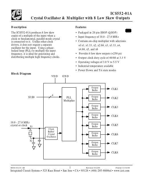
DescriptionThe ICS552-01A produces 8 low skew copies of a multiple of the input when a clock or fundamental, parallel-mode crystal is connected to it. Unlike other clock drivers, it does not require a separate oscillator for the input. Using a phase-locked loop (PLL) to multiply the input frequency, it is ideal for generating and distributing multiple high frequency clocks.Features• Packaged in 20 pin SSOP (QSOP)• Input frequency of 10.0 - 27.0 MHz• Contains on-chip multiplier with selections of x1, x1.33, x2, x2.66, x3, x3.33, x4, x4.66, x5, and x6• Provides 8 low skew outputs (<250 ps)• Output clock duty cycle of 40/60 at 3.3 V • Operating voltages of 3.0 V to 5.5 V • Industrial temperature available • Power Down and Tri state modesBlock DiagramCLK1CLK2CLK3CLK4CLK6CLK5CLK7CLK8Multiplier Select TablePin DescriptionsKey: I = Input; O = output; P = power supply connection, XI, XO = crystal connectionsVDD 20 pin SSOP (QSOP)DC CLK8S0CLK7CLK5S1CLK6GND S3Pin Assignment0 = connect directly to ground.1 = connect directly to VDD.All clocks stop low in Power Down state.All clocks outputs are high impedance in 1101 mode.Electrical Specificationsexposure to levels above the operating limits but below the Absolute Maximums may affect device reliability. External ComponentsA minimum number of external components are required for proper operation. A decoupling capacitor of0.01 uF should be connected between VDD and GND on pins 4 and 6, and 16 and 14. Other VDDs and GNDs can be connected to these pins or directly to their respective power planes. A 33 Ω series terminating resistor may be used on the clock output if the trace is longer than 1-inch.The crystal should be a fundamental mode (do not use third overtone), parallel resonant, with accuracy as required by the application. Crystal capacitors should be connected from pins X1 to ground and X2 to ground. The value of these capacitors is given by the following equation, where C L is the crystal load capacitance: Crystal caps (pF) = (C L-12) x 2. So for a crystal with 18pF load capacitance, two 12pF caps should be used. For a clock input, connect it to X1/ICLK, and leave X2 unconnected (floating).Ordering InformationWhile the information presented herein has been checked for both accuracy and reliability, Integrated Circuit Systems, Incorporated (ICS) assumes no responsibility for either its use or for the infringement of any patents or other rights of third parties, which would result from its use. No other circuits, patents, or licenses are implied. This product is intended for use in normal commercial applications. Any other applications such as those requiring extended temperature range, high reliability, or other extraordinaryenvironmental requirements are not recommended without additional processing by ICS. ICS reserves the right to change any circuitry or specifications without notice. ICS does not authorize or warrant any ICS product for use in life support devices or critical medical instruments.20 pin SSOPPackage Outline and Package Dimensions(For current dimensional specifications, see JEDEC Publication No. 95.)。
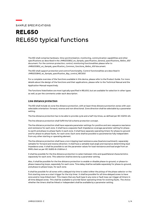
—SAMPLE SPECIFICATION SREL650REL650 typical functionsThe IED shall comprise hardware, time synchronization, monitoring, communication capabilities and otherspecifications as described in the 1MRG033852_en_Sample_specification_General_specifications_Relion_650document. For the common protection, control, monitoring functionalities please refer to1MRG033851_en_Sample_specification_Common_functions_Relion_650 document.The IED shall support protection and control functionality. Control functionalities are described in1MRG033849_en_Sample_specification_Bay_control_REC650.For a complete overview of the functions available in this device, please refer to the Product Guide. For moredetails about the design of the functions and their applications, please refer to the Technical Manual and theApplication Manual respectively.The functions listed below are most typically specified in REL650, but are available for selection in other typesas well, as per the comments under each description.Line distance protectionThe IED shall include six zone line distance protection, with at least three distance protection zones with user-selectable orientation: forward, reverse and non-directional. Zone direction shall be selectable by a parametersetting.The line distance protection has to be able to provide cycle and a half trip times, as defined per IEC 60255-121.The line distance protection shall fulfill the full-scheme protection concept.The line distance protection shall have separate parameter settings for positive and zero sequence reactanceand resistance for each zone. It shall have a separate fault impedance coverage parameter setting for phase-to-earth and phase-to-phase faults in each zone. It shall have separate operating timers for phase-to-groundand for phase-to-phase faults, for each zone. Each zone shall be possible to parameterize fully independentfrom any other starting or operating element.The line distance protection shall have a non-tripping load resistance area (load encroachment), separatelysettable for forward and reverse direction. It shall have a settable load angle and reactance determining loadimpedance area. It shall be possible to set the parameter values for load resistance and load angle from anMMS client as per IEC 61850-8-1 Edition 2.It shall be possible for the line distance protection to select between mho and quadrilateral characteristicsseparately for each zone. This selection shall be done by a parameter setting.Also, it shall be possible for the line distance protection to enable or disable phase-to-ground, or phase-to-phase measuring loops, separately for each zone. Time delay shall be settable separately for phase-to-ground,and phase-to-phase loops, for each zone.It shall be possible for all zones with a delayed trip time to select either the pickup of the phase-selector or thefirst starting zone as a start trigger for the trip timer. It shall be possible for all time-delayed zones to havezone and/or loop-linked start. This means that any fault type in any zone or fault loop can trigger all timers inall time delayed zones. This shall be available to provide faster operating times for evolving faults. The choicewhether the timers shall be linked or independent shall be available by a parameter setting.The line distance protection shall have the possibility of CVT type selection, in order to secure reliable opera-tion of the line distance protection during CVT transients. This choice of CVT type shall be available by a pa-rameter setting. At least one line distance protection zone has to be equipped with a load compensation algo-rithm.The IED shall be able to handle analog quantities that are obtained via conventional analog measurements or IEC 61850 9-2LE sampled values. The conventional analog measurements and IEC 61850 9-2LE sampled values can be combined in the same device.The zone blinders that are set in parameter settings shall be displayed graphically in the same software tool. In 650 series, this function is available in the following product types: RED650 and REL650.Power swingThe IED shall include a power swing function for blocking all line distance protection zones during power swing conditions. The power swing function shall be based on the measurement of time required for the impedance operating point to pass between settable quadrilateral impedance blinders.In 650 series, this function is available in the following product types: RED650 and REL650.Out-of-stepThe IED shall include impedance-based out-of-step functionality, with a lens characteristic dividable in two im-pedance zones. It shall have a selectable number of slips required for the operation of each of the two zones. In 650 series, this function is available only in REL650.Switch-onto-faultThe IED shall include a dedicated function for switch-onto-fault detection. This function shall issue an instan-taneous trip if a non-directional overreaching zone picks up, or if an integrated undervoltage and overcurrent detector picks up, or if any of the two picks up while the function is active. The principle applied shall be se-lectable by a parameter. The thresholds for the integrated undervoltage and overcurrent detector shall be con-figurable by a parameter setting. The function shall contain the following possibilities, configurable by the end user, that define when the function will be active:∙It shall monitor the circuit breaker position indication status, and be active whenever the circuit breaker is open, and for a set time after the circuit breaker is closed.∙It shall have the possibility of being active only for a set time after the circuit breaker close command is issued.∙It shall have the possibility of being active whenever an internal detector based on undervoltage and undercurrent declares that the line is not energized. Also, the function shall be active for a set timeafter the internal detector detects that the line was energized.∙It shall be capable of combining the explained principles and using them in parallel.In 650 series, this function is available in the following product types: REL650, and RED650.Fuse failure supervisionThe IED shall contain a fuse failure supervision function, in order to avoid inadvertent operation of voltage de-pendent functions when a failure in the voltage measurement circuit occurs.The fuse failure function shall comprise the following:∙Monitoring the status of an MCB or a fuse protecting the secondary wiring of the VT.∙Detection of a failure of the voltage measurements based on symmetrical components, independent from the MCB or fuse status; this feature shall be based on the detection of a high value of zero se-quence voltage (3U0>) and the absence of zero sequence current (3I0<), or the detection of a high-value of negative sequence voltage (3U2>) and the absence of negative sequence current (3I2<); theend user shall select if one of the two principles shall be used, and it shall be possible to choose acombination of the two principles as ´AND´ or ´OR´ logical combinations; it shall be possible for the algorithm to dynamically apply the zero-sequence algorithm if I0 > I2, and vice versa; the thresholdsfor 3U0>, 3I0<, 3U2> and 3I2< shall be settable by the end user.∙Detection of a failure of voltage measurements based on a three-phase change in voltage (DU), with-out a change in current (DI); this algorithm shall be independent from the other functionalities in-cluded in the function, and it shall be possible to enable by a parameter; the levels of DU and DI shall be settable by a setting parameter.∙The function shall be able to receive the position indication of the line disconnector, and block all voltage functions when the position is open.∙It shall be possible for the function to seal-in its output once it has picked up, and to store this infor-mation in non-volatile memory; the function shall reset once the voltage recovers, and the level of the reset voltage shall be settable by a parameter setting.In 650 series, this function is available in the following product types: REL650, RED650, REB650, REC650, REQ650, and RET650.Communication scheme for line distance and residual overcurrent protectionThe IED shall include line distance communication schemes, including permissive overreach, permissive un-derreach, intertripping and blocking schemes.The IED shall include a communication scheme and logic for weak-end infeed. This logic shall be used for lines with a strong infeed on one side and a weak infeed on the remote line end, or for radial lines. This logic shall enable an overreaching zone to trip instantaneously if the weak infeed line end does not detect the fault.The IED shall include current reversal logic for parallel lines that apply an overreaching permissive communica-tion scheme, to avoid unselective tripping due to current reversal.In 650 series, this function is available in the following product types: RED650 and REL650.Fault locatorThe IED shall have an accurate fault locator based on local impedance measurements, giving the distance to the fault in km, miles or percentage of line length. The fault locator shall have compensation for load current and for the mutual zero-sequence effect on double circuit lines, and it shall include settings of the remote and local sources to calculate the distribution of fault currents from each side. The fault locator shall have a static accuracy of 2%, when the voltage is between 0.1 and 1.1 times rated voltage, and when the current is from 0.5 to 30 times rated current.It shall be freely configurable which protection functions should trigger a fault locator calculation.It shall be possible to report the measured phase impedance to a client over MMS communication, as per IEC 61850-8-1.In 650 series, this function is available in the following product types: REC650, RED650 and REL650.AutorecloserThe IED shall include reclosing with five separately set time intervals for reclosing. The first attempt can be single-phase, two-phase and/or three-phase. Separately set reset times for the reclose cycle and for lockout shall be available.In multi-breaker applications, the autorecloser shall have a priority circuit, which allows a breaker to close first and a second breaker to close only if a fault proves to be transient.In 650 series, this function is available in the following product types: RED650, REL650 and REQ650.ABB ABGrid Automation Products SE-721 59 Västerås, Sweden Phone +46 (0) 21 32 50 00/protection-control Document ID: 1MRG033855 Issued: January 2019Revision: C。

Imprint:Instruction Manual R550 / R600 / R650 / R750© ROTHENBERGER Werkzeuge GmbH, 2003We reserve the right to revise product specifications at any time without notice. Editorial/Typeset/DTP: ROTHENBERGER Werkzeuge GmbH • D-65779 Kelkheim Edition 09 / 2003Printed in the F.R. of GermanyPlease read the Instruction Manual carefully first! • Don't throw it away! If damages are caused by operating errors or misuse the warranty expires!Contents PageComments 121. Safety1.1 Use in accordance with the regulations 121.2 Applied safety symbols and their meaning 121.3 Indication to the safety of man and machine 122. Technical Data 143. Function of the Unit 1414Description3.1Design/summery14Equipment3.1.1description14Functional3.1.2Operation153.23.3 Removal of pipe blockages 163.4 Retrieval of the spirals from the pipe 16Toolchanging 163.53.6 Working using 8 mm or 10 mm spirals 1717Shut-down3.74. Troubleshooting 17Repair 185. Serviceand5.1Service 1818Repair5.2Maintenance,Recondition,5.2.1 Changing of the clamp-mounting system 186. Disposal 197. CE-Statement of Conformity 198. Warranty s. appendix 11. Safety Comments1.1Use in accordance with the regulationsThe drain cleaning machines are only to be used for pipe cleaning of the following pipe-diameters:R550 20-100mm / R600-650 20-150mm / R750 20-200mmThe drain cleaning machines may not be operated under load longer than 15 minutes.1.2Applied safety symbols and their meaningFailure to comply with these safety marks (WARNING) means danger to life and health ofindividuals.Failure to comply with these safety marks (CAUTION) means a possibly dangerous situation whichmay result in injuries or damage to property.This symbol (NOTE) points to important advice for the proper handling of the machine. Failure tocomply with these notes may cause malfunction of themachine or interference to the environment.1.3 Indication to the safety of man and machineKeep your working area in an orderly state. Disorder can cause accidents!Bear ambient factors of influences in mind. Do not expose electrical power tools to rain.Do not use electrical power tools in damp or wet environments. Ensure good lighting. Do not useelectrical power tools in the proximity of combustible liquids or gasesProtect yourself from electric shock. Avoid bodily contact with earthed parts, e.g. pipes,radiators, cookers, refrigerators!Keep children away. Do not allow other persons to touch the tool or flex. Keep other personsaway from your working area.Store your tools safely. Unused tools should be stored in a dry and locked room and in such away that they are not accessible to children.Do not overload your tool. You will work better and more safely if you stay within thespecified capacity range.Use the proper tool. Do not use tools or adapter devices which are too weak for heavy work.Do not use tools for purposes and work for which they were not intended, e.g. do not usehandheld circular saws to cut trees or branches.Wear suitable work clothing. Do not wear wide clothing or jewellery, both of which can becaught by moving parts. When working outdoors, rubber gloves and anti-slip shoes are advisable.If your hair is long, wear a hairnet.Wear protective goggles. Use an oxygen mask for work where a dusty atmosphere is likely tobe generated.Do not misuse the flex. Do not carry the tool by the flex and do not use the flex to pull the plug out of the socket outlet. Protect the flex from heat, oil and sharp edges.Secure the work piece. Use clamping mechanisms or a vise in order to secure the work piece. In that way, the work piece is held more securely than when held by your hand and allows you instead to operate the machine using both hands.Do not overextend your standing area. Avoid abnormal postures. Ensure that you are standing safely and have proper balance at all times.Take care of your tools meticulously. Keep your tools sharp and clean to enable you to workwell and safely. Adhere to the maintenance instructions and the instructions for tool changing. Check the plug and the flex regularly and, if they are damaged, have them upgraded by an approved professional. Check the extension cable regularly and replace it if damaged. Keep the handgrips dry and free from oil and grease.Pull out the mains plug when not using the tool, before performing maintenance work and when changing a part of the tool, such as e.g. saw blade, drill and machine tools of all kinds.Do not leave a tool wrench inserted. Before switching on the power, check that the wrenches and setting tools are removed.Avoid starting the tool unintentionally. Do not carry tools which are connected to thepower mains while holding your finger on the switch. When plugging the tool into the power mains, make sure that the switch is off.Extension cables outdoors. When working outdoors, only use extension cables which areapproved for this purpose and correspondingly labelledBe at all times attentive. Monitor your work. Proceed rationally. Do not use the tool if you are not able to concentrateCheck your appliance for damage. Before using the tool any further, check carefully that the protective mechanisms and any slightly damaged parts are functioning perfectly and in line with the regulations and with their intended purpose. Check that the moving parts are functioning properly, that they are not stuck and that no parts are damaged. All parts must be mounted properly and all conditions fulfilled in order to ensure the sound operation of the appliance. Where not otherwise stated in the operating manuals, damaged protective devices and parts should be properly repaired by a customer service workshop or replaced by same. Damaged switches must be replaced by a customer service workshop. Do not use tools on which the power switch cannot be switched on and off .Caution. For your own safety, only use accessories and auxiliary devices which are specified foruse in the operating manual or recommended or specified by the tool manufacturer. The use of tools or accessories other than those recommended in the operating manual or in the catalogue can entail a danger of personal injury to you.Have your electrical power tools repaired by a skilled electrical specialist. ROTHENBERGER electrical power tools are in accordance with the relevant safety regulations. Repairs are only permitted to be performed by a skilled electrical specialist. Otherwise, accidents can happen to the user.Data2. TechnicalR550 R600 Saniclean R650 Powerclean R750 Motor rating 250 Watt 400 Watt 800 Watt 900 Watt07.2655 07.2665 07.2670 07.2910Voltage 230 V; 50 Hz 230 V; 50 Hz 220-240 V; 50 Hz 220-240 V; 50 Hz07.291107.2863 07.2869110/115V; 50Hz 110/115V; 50Hz 110/115V; 50Hz Operating speed 575 U/min 460 U/min 620 U/min 460 U/minWeight 15 kg 20,9 kg 22,8 kg 29,5 kgSpirals Ø16 Ø16; Ø22 Ø16; Ø22 Ø16; Ø22; Ø32(Ø8;Ø 10with (Ø8;Ø 10with (Ø8;Ø 10with (Ø8;Ø 10withaccessories) accessories) accessories) accessories) max. working length 40m 60m 65m 80mdiameterPipeRange Ø20-Ø100mm Ø20-Ø150mm Ø20-Ø150mm Ø20-Ø200mmNoise level 75 dB (A) 75 dB (A) 80 dB (A) 80 dB (A)I I I IclassProtectionUnitthe3. Functionof3.1 Design/Description3.1.1 Equipment summeryEquipment summary/Controls (>see fold-out page)Abb.1 : A = Hand lever B = Main switch C = SpiralD = ToolE = Holder for spiralF = Power cableAbb.2 : (Access.) G = Spirals H = Guide hose I = Spray for spiralK = safety gloves L = Tools3.1.2 FunctionaldescriptionIn the model R550 / R600 / R650 / R750, you have purchased a highly efficient, portable and easy-to-usedrain-cleaning machine.The machine functions on the "Sectional Cable" principle, i.e., only as many spirals as are necessary arecoupled together.This makes it possible to design the machine with a speed of rotation which permits efficient pipe cleaning witha diverse range of tools.The machine is electrically driven. The power of the motor is transmitted to the spirals via the clamp-mountingsystem by exerting pressure on the hand-lever.If the hand-lever is an inoperative position, you can push up the lockpin and the hand-lever can be used as antransport handle. If you push down the hand-lever , the locking is released.By model R650 Powerclean , the hand-lever can be installed either as a centre-mounted or as a side-mountedlever.By model R750 the Handle can also be swung backwards through 180° and locked whenwheeling the machine.Lockpin of hand leverR 650 Powerclean R 750Forward movement towards the pipe blockage is sensitively generated via a so-called working arc on the spiralsbetween the machine and the pipe to be cleaned.The machine is designed for the following diameter spirals:R550 ∅ 16mmR600/650 ∅ 16, 22mmR750 ∅ 16, 22, 32mmAccessories make it possible to use 8 mm and 10 mm diameter spirals for tight bends in sanitary systems.Maximum working range is around the following spiral length :R55040mspirallengthR60060mspirallengthR650/75080mspirallength3.2 OperationWarning! The operation of the drain-cleaning machines shall only be carried outobserving all notes concerning the safety of man and machine.The machine should be positioned at a distance of 50 to 80 cm from the entry to the pipe to be cleaned; themains plug should be connected to the correct electrical supply.If 16 mm or 22 mm diameter spirals are to be used, the fixing element of the guide hose should be insertedinto the hole on the rear of the machine and correctly locked using the attached fixing element and catcher.The guide hose serves as a vibration-absorbing guide element for the spirals, as a dirt trap, and as a safetyelement for the operating staff.The spiral should now be inserted into the machine and coupled at the front by means of a suitable tool. Thetool should be selected to accord with the suspected type of fouling.Important! Put on safety gloves before any other actions are performed!CatcherThe spiral should now be inserted approx. 500 mm into the pipe to be cleaned and the drain-cleaning machinestarted in forward mode. The spirals should be moved manually toward the point of fouling. Once a slightresistance is felt (blockage), the spirals should again be withdrawn from the machine until an arc relative to thepipe occurs. This so-called working arc should be maintained with one hand (wear gloves!) while the hand-lever is pressed down using the other hand; the spirals will now start to rotate.3.3Removal of pipe blockagesThe working arc produced should be pressed downward by the operator, generating a pressure towards theblockage with the drain-cleaning machine remaining in its position. The working pressure resulting from thespirals intrinsic tension and manual pressure acts against the blockage in the pipe.Once the pre-tensioned working arc has penetrated into the pipe, the hand-lever should be released and thespirals again withdrawn from the machine in order to create a new working arc. This cycle of creation of aworking arc and pushing of the rotating spirals towards the blockage should be repeated until the blockagehas been eliminated.Practical experience indicates that the pipe should be finely "after-cleaned" using a chain flail once theblockage has been dislodged.Note:If a tool has become jammed in the pipe, the machine should be set to reverse and the spirals disengaged fromthe blockage by means of backward and forward movements. The machine should then be reset to forwardand the spirals moved up to the blockage again. The procedure for removal of the blockage should then becontinued as described above3.4 Retrieval of the spirals from the pipeUse one hand to draw the rotating spirals out of the pipe until a slight arc is formed. The hand-lever should bereleased and the motionless spirals then pushed back into the machine. The hand-lever should then be used toclamp and rotate the spirals again. As already described, the spirals should then be drawn further out of thepipe. Once a length of spiral has been returned to the guide tube, it should be uncoupled and drawn out of theguide hose. These sequences should be repeated until all the sections of spiral have been removed from thepipe.3.5 ToolchangingThe most efficient tool for the particular type of blockage should be selected.Tool-changing is performed as follows:the tool attachment key supplied with the machine should beinserted into the side boring of the coupling on the spiralsthe locking bolt of the 2nd half-coupling should be liftedthe coupling should be removed to the side out of the milled recessThe tool selected should be mounted from the side on the couplingworking arc3.6 Working using 8 mm or 10 mm spirals8 mm or 10 mm spirals should be used for narrow pipes and pipe bends. An adapter magazine available as an accessory is needed for this purpose; this contains an 8 mm or 10 mm spirals in a drum (for R750 clamp clips are needed).The adapter magazine should be installed in place of the guide tube.For R750, push the suit clamp clip over the spiral into the boring until the stop face.Work then continues in the same way as with a standard spiral.An adjustable brake is provided on the machine to prevent co-rotation of the adapter magazine. The braking action is achieved by lifting the hand-lever to its extreme end position. If there is no longer an adequatebraking action, the setscrew on the adapter should be slackened and the distance between the casting and the clamp corrected. The setscrew should then be re-tightened.3.7 Shut-down After use of the machine, the rotary switch should be returned to its "0" position and the mains plugdisconnected from the mains. The spirals should be recovered from the pipe as described in Section 3.4. and removed from the machine. The guide hose or the adapter magazine should then be detached from the machine.4. TroubleshootingTroublepossible cause Remedy Machine does not work - no power - check the power supply system - defect of main switch - Contact your service agent - defect of motor - Contact your service agent No rotation of spiral - abrasion of clamp clips - remove clamp clips by using the hand-lever - abrasion of cogged belt - remove cogged belt Adapter with setscrew Adapter magazine incl. spiraleClamp clip for R7505 Service and Repair5.1 ServiceThe machine must be carefully handled and must be cleaned at regular intervals. The spirals and tools must be cleaned and protected after every use. We recommend our special "ROWONAL" care product for this purpose. The machine has one lubricating point on the top exterior and internally for lubrication of the needle bearings. The outer lubricating point must be greased using a universal grease after every five hours of operation. The bearings inside the machine can be reached only by dismantling the right-hand side cover. Lubrication here is recommendable at intervals of one hundred hours of operation.5.2 Maintenance, Recondition, RepairImportant!All maintenance, recondition and repair work shall only be carried out by an introduced professional repairing person.The Rothenberger service locations or else the manufacturer with his repair department are available to help you. Needless to say, we will also send you spare parts at short notice. Please contact please your retailer or the manufacturer.Order your accessories and spare parts from your specialist retailer or using our after-sales hotline:Tel. +49 6195 99 52 14 Fax: +49 6195 99 52 155.2.1 Changing of the clamp-mounting systemWarning! Before changing the clamp-mounting system pull out the power cable of the plug connection!1. Dismantle the cover on the right-hand sideGrease nipple outside Needle bearing Grease nipple is being oppositeplug2. Remove the plug and slacken the locking nut.3. Turn the adjusting screw backwards until the clamp-mounting springs are detensioned and remove theclamp-mounting system.4. Insert the new clamp-mounting system and turn the adjusting screw until the correct functioning position forbraking of the adapter magazine has been reached5. Tighten the locking nut and re-install the plugModel R750 :1.Dismantle the cover on the right-hand side2. Remove the clutch jaws and replace with new oneClutch jaws6. DisposalComponents of the unit are recyclable material and should be put to recycling. For this purpose registered andcertified recycling companies are available. For an environmental-friendly disposal of the non-recyclable parts(e.g. electronic waste)please contact your local waste disposal authority.7. CE-Statement of ConformityWe hereby declare on our sole responsibility that this product is in accordance with the provisions of theDirective 98/37EWG; 73/23EWG; 89/336EWG.For additional information, please contact us at the following postal address or contact one of the subsidiarycompanies specified.Rothenberger Werkzeuge GmbHIndustriestrasse7KelkheimD-65779Germany。

REF01数据表1、元器件参数特性1)High output accuracy(高输出精度)REF01: 10.0 V, ±0.3% maximumREF02: 5.0 V, ±0.3% maximumREF03: 2.5 V, ±0.6% maximum2)Excellent temperature stability(良好的温度稳定特性)REF01: 8.5 ppm/°C maximumREF02: 8.5 ppm/°C maximumREF03: 50 ppm/°C maximum3)Low noise(低噪声)REF01: 30 µV p-p typicalREF02: 15 µV p-p typicalREF03: 6 µV p-p typical最高供电电压范围:最大达36 V最低供电电流:最大值为1.4 mA高负荷驱动能力:最大10 mA(最大输出负载电流)温度输出功能(温度监控)应用场景精密数据系统高分辨率转换器工业过程控制系统精密仪器军事和航空航天应用概述REF01/REF02/REF03系列精密电压参考产品提供了稳定的10.0 V、5.0 V或2.5 V输出,且随供应电压、环境温度或负载条件的变化影响最小。
该设备有8引脚的SOIC、PDIP、CERDIP 和TO-99封装,以及20端口的LCC封装(仅883),进一步提高了该设备在标准和高压力应用中的可用性。
通过一个外部缓冲器和一个简单的电阻网络,TEMP终端可以用于温度传感和近似。
在该装置上还提供了一个TRIM端子,用于微调输出电压。
REF01、REF02/REF03系列应用非常适合通用和空间受限的应用。
较新的设计应使用ADR01/ADR02/ADR03/ADR06系列参考文献,可提供更高的精度和温度。
1、引脚配置不同封装下的引脚图如下:注:NC = NO CONNECT ,即不要在这些引脚上连接任何东西。


PT2C-1965内置信号转换器的气体检测部SD-1DRI使用说明书(PT2-196)(PT2E-196)邮编:174-8744 日本东京都板桥区小豆泽2-7-6网页 https://www.rikenkeiki.co.jp/使用注意事项本仪器是气体警报器,具有检测大气中的可燃性,并发出警报的功能。
气体警报器是安保仪器,并非分析、测定气体的定量及定性的分析计、浓度计。
请充分理解以下要点,正确使用仪器。
1.本仪器会受到检测对象气体以外的气体及蒸汽的干扰。
请注意干扰造成的警报运行。
另外,可能因设置场所的环境变化(温度、湿度等)而发生变动。
请定期(1个月左右)实施零位调整。
2.请勿在温度大幅(约10~15℃以上)变化的场所使用本仪器。
3.警报的设定请在符合仪器性能的范围内使用。
符合高压气体保安法的设备设定的警报如低于本公司标准警报设定值时,可能造成错误警报。
4.本仪器是安保仪器,并非控制仪器。
本仪器的警报接点输出请用于外部警报指示灯及蜂鸣器,模拟信号输出请用于指示器或外部记录器。
用于其他控制用途时,本公司不对误动作等进行任何补偿。
5.在高湿度及有粉尘、酸雾的场所进行气体取样时,需要预处理装置,请洽询。
6.进行本仪器的保养时,需要进行包括使用说明书中记载的定期更换部件的更换调整在内的定期点检。
2目录1.产品概述1-1.前言 (2)1-2.使用目的 (2)1-3.危险、警告、注意、注记的定义 (2)1-4.标准及防爆规格的确认方法 (2)2.安全重要事项2-1.危险事项 (4)2-2.警告事项 (4)2-3.注意事项 (6)2-4.安全信息 (7)3.产品构成3-1.主机及标准附件 (9)3-2.各部的名称和功能 (10)3-3.框图 (11)4.使用方法4-1.使用之前 (12)4-2.安装场所相关的注意事项 (12)4-3.系统设计上的注意事项 (13)4-4.安装方法 (15)4-5.装配方法 (16)4-6.配线方法 (17)4-7.配管方法 (22)5.操作方法5-1.起动准备 (23)5-2.基本动作流程 (23)5-3.起动方法 (24)5-4.关于各种模式 (25)5-5.维护模式(用户) (27)5-6.结束方法 (29)6.各种动作及功能6-1.气体警报动作 (30)6-2.故障警报动作 (31)6-3.外部输出动作 (32)6-4.关于各种功能 (34)7.保养点检7-1.点检频度和点检项目 (35)7-2.维护模式(定期点检) (37)7-3.气体校准方法 (45)7-4.部件的更换 (48)8.关于储存、移设及废弃8-1.储存或长期不使用时的处理 (50)8-2.移设或重新使用时的处理 (50)8-3.产品的废弃 (50)9.故障检修 (51)10.产品规格10-1.规格一览 (53)10-2.检测原理 (61)11.术语的定义 (62)1CE/UKCA标志规格的标牌示例Ex规格的标牌示例 ATEX/IECEx/UKEX,Japan3施加过大的压力。

Ra-01S规格书版本V1.1版权©2020免责申明和版权公告本文中的信息,包括供参考的URL地址,如有变更,恕不另行通知。
文档“按现状”提供,不负任何担保责任,包括对适销性、适用于特定用途或非侵权性的任何担保,和任何提案、规格或样品在他处提到的任何担保。
本文档不负任何责任,包括使用本文档内信息产生的侵犯任何专利权行为的责任。
本文档在此未以禁止反言或其他方式授予任何知识产权使用许可,不管是明示许可还是暗示许可。
文中所得测试数据均为安信可实验室测试所得,实际结果可能略有差异。
文中提到的所有商标名称、商标和注册商标均属其各自所有者的财产,特此声明。
最终解释权归深圳市安信可科技有限公司所有。
注意由于产品版本升级或其他原因,本手册内容有可能变更。
深圳市安信可科技有限公司保留在没有任何通知或者提示的情况下对本手册的内容进行修改的权利。
本手册仅作为使用指导,深圳市安信可科技有限公司尽全力在本手册中提供准确的信息,但是深圳市安信可科技有限公司并不确保手册内容完全没有错误,本手册中的所有陈述、信息和建议也不构成任何明示或暗示的担保。
文件制定/修订/废止履历表版本日期制定/修订内容制定核准V1.02020.8.12首版徐V1.12020.8.19更新部分参数徐目录一、产品概述 (5)二、电气参数 (6)三、外观尺寸 (8)四、管脚定义 (10)五、原理图 (11)六、设计指导 (12)七、回流焊曲线图 (14)八、包装信息 (15)九、联系我们 (15)一、产品概述安信可LoRa系列模块(Ra-01S)由安信可科技设计开发。
该模组用于超长距离扩频通信,其射频芯片SX1268主要采用LoRa™远程调制解调器,用于超长距离扩频通信,抗干扰性强,能够最大限度降低电流消耗。
借助SEMTECH的LoRa™专利调制技术,SX1268具有超过-148dBm的高灵敏度,+22dBm的功率输出,传输距离远,可靠性高。
同时,相对传统调制技术,LoRa™调制技术在抗阻塞和选择方面也具有明显优势,解决了传统设计方案无法同时兼顾距离、抗干扰和功耗的问题。

上海ABB工程有限公司REC650 CN01-AE-A 配置描述上海ABB工程有限公司REC650 CN01-AE-A 配置描述一,装置功能概述:◆REC650可作为配电网中架空线和电缆馈线的保护。
主要用于电力变电站、电厂等电力行业以及水泥、冶金、石化、汽车、半导体、造纸、烟草等工业用户,也可用于市政、机场、港口、房地产等行业。
◆硬件描述:机箱尺寸6U ½19’’一个通讯处理模块COM(带有14个开关量输入通道)一个电源模块PSM03(带有9个开关量输出通道)◆保护功能:电流保护:电流速断,带方向的4段过流保护;零序速断,带方向的4段零序过流保护。
电压保护:两段带时限的零序过电压保护;两段带时限的过电压保护;两段带时限的低电压保护。
频率保护:两段低频率保护,两段过频率保护,两段频率变化率保护。
◆监控功能:装置大液晶单线图显示,包括:一个断路器位置监测显示,实现就地远方控制;一个小车位置监测显示;一个地刀位置监测显示。
◆测量功能:大液晶独立页显示测量量:三个线电压,三相相电压,一个零序电压,三相电流,一个有功功率,一个无功功率和一个频率。
◆二次回路监测功能:PT断线保护。
上海ABB工程有限公司REC650 CN01-AE-A 配置描述二.功能配置图上海ABB工程有限公司REC650 CN01-AE-A 配置描述三,预配置保护逻辑详解A.功能逻辑配置目录上海ABB工程有限公司REC650 CN01-AE-A 配置描述B. AI 模拟量输入信号逻辑图BUS VT A U3P处理周期为5ms,BUS_VT_A_UL1, BUS_VT_A_UL2, BUS_VT_A_UL3,分别为模拟量录波用。
BUS VT B U3P处理周期为20ms,BUS_VT_B_3PH为保护使用。
BUS VT A 3U0处理周期为5ms,BUS_VT_A_U0为模拟量录波用。
BUS VT B U3P处理周期为20ms,BUS_VT_B_3U0为保护使用。
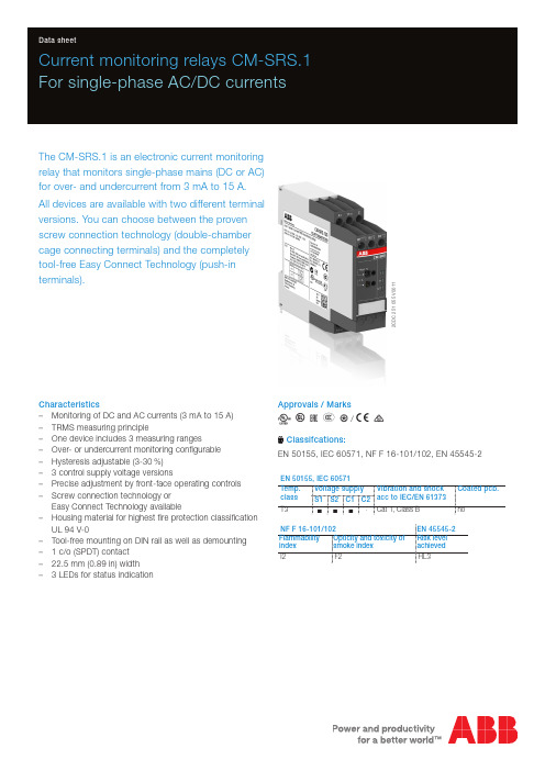
2C D C 251 055 V 0011Current monitoring relays CM-SRS.1For single-phase AC/DC currentsThe CM-SRS.1 is an electronic current monitoring relay that monitors single-phase mains (DC or AC) for over- and undercurrent from 3 mA to 15 A.All devices are available with two different terminal versions. You can choose between the proven screw connection technology (double-chamber cage connecting terminals) and the completely tool-free Easy Connect Technology (push-in terminals).Characteristics–Monitoring of DC and AC currents (3 mA to 15 A) –TRMS measuring principle–One device includes 3 measuring ranges–Over- or undercurrent monitoring configurable –Hysteresis adjustable (3-30 %) – 3 control supply voltage versions–Precise adjustment by front-face operating controls –Screw connection technology orEasy Connect Technology available–Housing material for highest fire protection classificationUL 94 V-0–Tool-free mounting on DIN rail as well as demounting – 1 c/o (SPDT) contact –22.5 mm (0.89 in) width – 3 LEDs for status indicationApprovals / MarksA C R E L /a bClassifcations:EN 50155, IEC 60571, NF F 16-101/102, EN 45545-2EN 50155, IEC 60571Temp. class Voltage supply Vibration and shockacc to IEC/EN 61373Coated pcb.S1S2C1C2T3nnn-Cat 1, Class BnoNF F 16-101/102EN 45545-2Flammability index Opticity and toxicity of smoke index Risk level achieved I2F2HL3Order dataCurrent monitoring relaysType Rated control supply voltage Connection technology Measuring ranges Order code CM-SRS.11P24-240 V AC/DC Push-in terminals3-30 mA, 10-100 mA, 0.1-1 A1SVR740840R0200 110-130 V AC1SVR740841R0200220-240 V AC1SVR740841R1200 CM-SRS.11S24-240 V AC/DC Screw type terminals3-30 mA, 10-100 mA, 0.1-1 A1SVR730840R0200 110-130 V AC1SVR730841R0200220-240 V AC1SVR730841R1200 CM-SRS.12S24-240 V AC/DC Screw type terminals0.3-1.5 A, 1-5 A, 3-15 A1SVR730840R0300 110-130 V AC1SVR730841R0300220-240 V AC1SVR730841R1300AccessoriesType Description Order code ADP.01Adapter for screw mounting1SVR430029R0100 MAR.12Marker label for devices with DIP switches1SVR730006R0000 COV.11Sealable transparent cover1SVR730005R01002 - Current monitoring relays CM-SRS.1 | Data sheetData sheet | Current monitoring relays CM-SRS.1 - 3Connection technologyMaintenance free Easy Connect Technology with push-in terminalsType designation CM-xxS.yyPApproved screw connection technology with double-chamber cage connecting terminals Type designation CM-xxS.yySPush-in terminals–Tool-free connection of rigid and flexible wires withwire end ferrule–Easy connection of flexible wires without wire endferrule by opening the terminals –No retightening necessary–One operation lever for opening both connectingterminals–For triggering the lever and disconnecting of wiresyou can use the same tool (Screwdriver according to DIN ISO 2380-1 Form A 0.8 x 4 mm (0.0315 x 0.157 in), DIN ISO 8764-1 PZ1 ø 4.5 mm (0.177 in))–Constant spring force on terminal point independentof the applied wire type, wire size or ambientconditions (e. g. vibrations or temperature changes) –Opening for testing the electrical contacting –Gas-tightDouble-chamber cage connecting terminals–Terminal spaces for different wire sizes–One screw for opening and closing of both cages –Pozidrive screws for pan- or crosshead screwdriversaccording to DIN ISO 2380-1 Form A 0.8 x 4 mm (0.0315 x 0.157 in), DIN ISO 8764-1 PZ1 ø 4.5 mm (0.177 in)Both the Easy Connect Technology with push-in terminals and screw connection technology with double-chamber cageconnecting terminals have the same connection geometry as well as terminal position.2C D C 253 025 F 00112C D C 253 026 F 00114 - Current monitoring relays CM-SRS.1 | Data sheetFunctions Operating controls2C D C 251 055 V 00111 Adjustment of the hysteresis (MIN = Default)2 Adjustment of the threshold value (MIN = Default)3 Indication of operational states U/T: green LED – control supply voltage R: yellow LED – relay status I: red LED – over- / undercurrent4 DIP switches (see DIP switch functions)ApplicationThe current monitoring relays CM-SRS.1 are designed for use in single-phase AC and/or DC systems for over- orundercurrent monitoring. The devices are available with different supply voltage ranges and work according to the open-circuit principle. Operating modeThe CM-SRS.1 with 1 c/o (SPDT) contact are available in 2 versions with 3 measuring ranges: 3-30 mA, 10-100 mA, 0.1-1 A (CM-SRS.11) and 0.3-1.5 A, 1-5 A, 3-15 A (CM-SRS.12). The measuring range is selected by connecting the monitored wire to the corresponding terminal B1/B2/B3-C.The units are adjusted with front-face operating controls. The selection of over- b or undercurrent monitoring a ismade with a DIP switch. Potentiometers, with direct reading scale, allow the adjustment of the threshold value I and of the hysteresis %. The hysteresis % is adjustable within a range of 3 to 30 % of the threshold value.Function diagramsOvercurrent monitoring bThe current to be monitored (measured value) is applied to terminals B1/B2/B3-C. The control supply voltage applied to terminals A1-A2 is displayed by the glowing green LED.If the measured value exceeds the adjusted threshold value, the output relay energizes and the red LED (overcurrent) andthe yellow LED (relay energized) glow.If the measured value drops below the threshold value minus the adjusted hysteresis, the output relay de-energizes and the red and yellow LEDs turn off.Undercurrent monitoring aThe current to be monitored (measured value) is applied to terminals B1/B2/B3-C. The control supply voltage applied to terminals A1-A2 is displayed by the glowing green LED.If the measured value drops below the adjusted threshold value, the output relay energizes, the red LED flashes W (undercurrent) and the yellow LED (relay energized) glows.If the measured value exceeds the threshold value plus the adjusted hysteresis, the output relay de-energizes and the red and yellow LEDs turn off.Data sheet | Current monitoring relays CM-SRS.1 - 5Electrical connectionDIP switches6 - Current monitoring relays CM-SRS.1 | Data sheetTechnical dataData at T a = 25 °C and rated values, unless otherwise indicatedInput circuitsSupply circuit A1-A2Rated control supply voltage U s110-130 V AC220-240 V AC24-240 V AC/DC Rated control supply voltage U s tolerance-15...+10 %Rated frequency50/60 Hz50/60 Hz or DC Typical current / power consumption24 V DC--30 mA / 0.75 W115 V AC24 mA / 2.6 VA-17 mA / 1.9 VA230 V AC-12 mA / 2.6 VA11 mA / 2.6 VA Power failure buffering time20 msTransient overvoltage protection varistorsMeasuring circuit B1/B2/B3-CMonitoring function over- or undercurrent monitoring configurableMeasuring method TRMS measuring principleMeasuring inputs CM-SRS.11CM-SRS.121)terminal connection B1-C B2-C B3-C B1-C B2-C B3-Cmeasuring range3-30 mA10-100 mA0.1-1 A0.3-1.5 A1-5 A3-15 Ainput resistance 3.3 Ω 1 Ω0.1 Ω0.05 Ω0.01 Ω0.0025 Ωpulse overload capacity t < 1 s500 mA 1 A10 A15 A50 A100 Acontinuous capacity50 mA150 mA 1.5 A 2 A7 A17 A Threshold value adjustable within the indicated measuring range Tolerance of the adjusted threshold value10 % of the range end valueHysteresis related to the threshold value3-30 % adjustableMeasuring signal frequency range DC / 15 Hz - 2 kHzRated measuring signal frequency range DC / 50-60 HzMaximum response time AC80 msDC120 msAccuracy within the rated control supply voltage toleranceΔU ≤ 0.5 %Accuracy within the temperature rangeΔU ≤ 0.06 % / °CTiming circuitTime delay T V noneRepeat accuracy (constant parameters)±0.07 % of full scaleUser interfaceIndication of operational statesControl supply voltage U/T: green LED V: control supply voltage appliedMeasured value I: red LED V: overcurrentW: undercurrentRelay status R: yellow LED V: output relay energized1) For usage of the current monitoring relays according to UL, following limitations for the measuring circuits are applicable: The load on any single measuring circuit should not exceed15 A at 51-150 V, 10 A at 151-300 V or 5 A at 301-600 V.This limitation is only valid for application according to UL and not for IEC applications.Data sheet | Current monitoring relays CM-SRS.1 - 7Output circuitsKind of output1115-1216/1418relay, 1 c/o (SPDT) contactOperating principle open-circuit principle (output relay energizes if themeasured value exceeds b / falls below a theadjusted threshold value)Contact material AgNiRated operational voltage U e250 VMinimum switching voltage / Minimum switching current24 V / 10 mAMaximum switching voltage / Maximum switching current250 V AC / 4 A ACRated operational current I e AC-12 (resistive) at 230 V 4 AAC-15 (inductive) at 230 V 3 ADC-12 (resistive) at 24 V 4 ADC-13 (inductive) at 24 V 2 AAC rating (UL 508)utilization category (Control Circuit Rating Code) B 300max. rated operational voltage300 V ACmax. continuous thermal current at B 300 5 Amax. making/breakingapparent power at B 3003600/360 VAMechanical lifetime30 x 106 switching cyclesElectrical lifetime AC-12, 230 V, 4 A0.1 x 106 switching cyclesMaximum fuse rating to achieve short-circuit protection n/c contact 6 A fast-acting n/o contact 10 A fast-actingGeneral dataMTBF on requestDuty time100 %Dimensions (W x H x D)product dimensions22,5 x 85,6 x 103,7 mm (0,89 x 3,37 x 4,08 in)packaging dimensions97 x 109 x 30 mm (3,82 x 4,29 x 1,18 in)Weight Screw connectiontechnology Easy Connect Technology (Push-in)net weight CM-SRS.11Version 24-240 V AC/DC0.145 kg (0.320 lb)0.137 kg (0.302 lb)Version 110-130 V AC 0.161 kg (0.355 lb)0.153 kg (0.337 lb)Version 220-240 V AC0.161 kg (0.355 lb)0.153 kg (0.337 lb)CM-SRS.12Version 24-240 V AC/DC0.137 kg (0.302 lb)-Version 110-130 V AC 0.168 kg (0.370 lb)-Version 220-240 V AC0.168 kg (0.370 lb)-gross weight CM-SRS.11Version 24-240 V AC/DC0.147 kg (0.324 lb)0.159 kg (0.351 lb)Version 110-130 V AC 0.183 kg (0.403 lb)0.175 kg (0.386 lb)Version 220-240 V AC0.183 kg (0.403 lb)0.175 kg (0.386 lb)CM-SRS.12Version 24-240 V AC/DC0.159 kg (0.351 lb)-Version 110-130 V AC 0.200 kg (0.441 lb)-Version 220-240 V AC0.200 kg (0.441 lb)-Mounting DIN rail (IEC/EN 60715),snap-on mounting without any tool Mounting position anyMinimum distance to other units10 mm (0.39 in) at measured current > 10 A Material of housing UL 94 V-0Degree of protection housing IP50terminals IP208 - Current monitoring relays CM-SRS.1 | Data sheetElectrical connectionEnvironmental dataAmbient temperature ranges operation-25...+60 °C (-13...+140 °F)storage-40...+85 °C (-40...+185 °F)Damp heat, cyclic (IEC/EN 60068-2-30)55 °C, 6 cyclesVibration, sinusoidal Class 2Shock Class 2Isolation dataRated insulation voltage U i supply / measuring circuit / output 600 Voutput 1 / output 2250 VRated impulse withstand voltage U imp supply / measuring circuit / output 6 kV 1.2/50 μsoutput 1 / output 2 4 kV 1.2/50 μsPollution degree3Overvoltage category IIIStandards / DirectivesStandards IEC/EN 60947-5-1, IEC/EN 60255-27, EN 50178 Low Voltage Directive2014/35/EUEMC Directive2014/30/EURoHS Directive2011/65/EURailway application standardsEN 50155, IEC 60571“Railway applications – Electronic equipment used on rolling stock”temperature class T3 supply voltage category S1, S2, C1IEC/EN 61373“Railway applications – Rolling stock equipment – Shock and vibration tests”Category 1, Class BEN 45545-2 Railway applications – Fire protection on railway vehicles – part 2:Requirements for fire behavior of materialsHL3and components ISO 4589-2LOI 32.3 %NF X-70-100-1 C.I.T. (T12) 0.45EN ISO 5659-2Ds max (T10.03) 104NF F 16-101: Rolling stock. Fire behaviour. Materials choosingNF F 16-102: Railway rolling stock. Fire behaviour. Materials choosing, application forelectric equipmentI2 / F2DIN 5510-2 Preventive fire protection in railway vehicles. Part 2: Fire behaviour and fireside effects of materials and partsfullfilledData sheet | Current monitoring relays CM-SRS.1 - 9Electromagnetic compatibilityInterference immunity to IEC/EN 61000-6-2 electrostatic discharge IEC/EN 61000-4-2Level 3radiated, radio-frequency, electromagnetic field IEC/EN 61000-4-3Level 3electrical fast transient / burst IEC/EN 61000-4-4Level 3surge IEC/EN 61000-4-5Level 3conducted disturbances, induced byIEC/EN 61000-4-6Level 3 radio-frequency fieldsInterference emission IEC/EN 61000-6-3 high-frequency radiated IEC/CISPR 22, EN 55022Class Bhigh-frequency conducted IEC/CISPR 22, EN 55022Class BTechnical diagramsLoad limit curvesDC load (resistive)AC load (resistive)Derating factor F for inductive AC loadContact lifetime10 - Current monitoring relays CM-SRS.1 | Data sheetDimensionsin mm and inchesAccessoriesin mm and inchesCOV.11 - Sealable transparent coverADP.01 - Adapter for screw mounting MAR.12 - Marker label for deviceswith DIP switchesFurther documentationDocument title Document type Document numberElectronic products and relays Technical catalogue2CDC 110 004 C02xxCM-SRS.1, CM-SRS.2Instruction manual1SVC 730 610 M0000You can find the documentation on the internet at /lowvoltage-> Automation, control and protection -> Electronic relays and controls -> Measuring and monitoring relays.CAD system filesYou can find the CAD files for CAD systems at -> Low Voltage Products & Systems -> Control Products -> Electronic Relays and Controls.Data sheet | Current monitoring relays CM-SRS.1 - 11ABB STOTZ-KONTAKT GmbHP. O. Box 10 16 8069006 Heidelberg, Germany Phone: +49 (0) 6221 7 01-0Fax: +49 (0) 6221 7 01-13 25E-mail:*****************.comYou can find the address of your local sales organisation on theABB home page/contacts-> Low Voltage Products and Systems Contact usNote:We reserve the right to make technical changes or modify the contents of this document without prior notice. With regard to purchase orders, the agreed particulars shall prevail. ABB AG does not accept any responsibility whatsoever for potential errors or possible lack of information in this document.We reserve all rights in this document and in the subject matter and illustrations contained therein. Any reproduction, disclosure to third parties or utilization of its contents – in wholeor in parts – is forbidden without prior written consent of ABB AG.Copyright© 2019 ABBAll rights reserved D o c u m e n t n u m b e r 2 C D C 1 1 2 1 6 7 D 0 2 0 1 R e v D ( 0 3 / 2 0 1 9 )。

2018产品说明书PRODUCT MANUAL深圳市叁叶源主要生产被动元器件SMD R‐Chip 电阻,产品尺寸:0402‐1206,阻值范围:1‐22兆欧姆,产品具有高可靠性电极设计、兼容所有焊接制程等特点。
Administrator深圳市叁叶源电子有限公司2018/6/1目录Contents●特点Features3●品名构成Type Designation3●结构Construction4●规格尺寸Dimensions4●负荷下降曲线Derating Curve4●额定值Ratings5●常规TCR值5●高精度TCR±50额定值6●特性Characteristics6●推荐焊盘尺寸Recommend Solder Pad Size9●包装Packaging9●IEC E-24、E-96系列电阻值代码对照表12●厚膜电阻阻值代码及标记规则14●片式电阻器使用说明16●焊接Soldering17■常规厚膜片式固定电阻器General Thick Film Chip Fixed Resistor●特点Features体积小、重量轻Miniature and light weight 适应再流焊与波峰焊Suit for reflow and wave flow solder 电性能稳定,可靠性高Stable electrical capability,high reliability 装配成本低,并与自动贴装设备匹配Low assembly cost,suit for automatic SMT equipment 机械强度高,高频特性优越Superior mechanical and frequency characteristics 符合RoHS 指令要求Compliant with RoHS directive 符合无卤素Halogen free requirement●品名构成Type Designation Single Chip ResistorSY 0402J N 100R P (1)(2)(3)(4)(5)(6)(1)(2)(3)(4)(5)(6)SeriesSize Reslstance Toleiance TCRResistance Packing style SY Thinck Film ST Thinck FilmSA Atuomotive Garde0402060308051206B=±0.1%D=±0.5%F=±1%J=±5%N=Base on Spc E=±50ppm/℃D=±25ppm/℃F=±100ppm/℃G=±200ppm/℃1K 100K 10R 4K71MP=Pager TapeB=Embossed Plastic●结构Construction①陶瓷基板Ceramic Substrate ②背电极Bottom Electrode ③面电极Top Electrode ④电阻体Resistor Layer ⑤一次保护Primary Overcoat ⑥二次保护Secondary Overcoat ⑦端电极Edge Electrode ⑧中间电极Barrier Layer ⑨外部电极External Electrode●规格尺寸Dimensions型号Type 尺寸Dimensions(mm)L W t a b 0402 1.00±0.100.50±0.050.35±0.050.20±0.100.25±0.100603 1.60±0.100.80±0.100.45±0.100.30±0.200.30±0.200805 2.00±0.15 1.25+0.15-0.100.55±0.100.40±0.200.40±0.2012063.10±0.151.55+0.15-0.100.55±0.100.45±0.200.45±0.20●负荷下降曲线Derating Curve额定负荷百分比Percent Rated Load环境温度Ambient temperature(℃)使用温度范围:OperatingTemperature Range:①-55℃~125℃②-55℃~155℃注1:图中曲线适用于适用于0402、0603、0805、1206。

DS650-6 June ‘06©2006 RF Solutions Ltd, Page 1Tel 01273 898000 Fax 01273 480661S MART R ADIO T RANSCEIVER RF650ApplicationsWireless Security Systems 元器件交易网DS650-6 June ‘06©2006 RF Solutions Ltd, Page 2Tel 01273 898000 Fax 01273 480661S MART R ADIO T RANSCEIVER RF650Table Of Contents1 M o d u l e C o n n e c t i o n s ................................................................................................................3 2O p e r a t i o n .................................................................................................................................4 2.1 O p e r a t i o n M o d e s ..............................................................................................................4 2.2 S e r i a l D a t a F o r m a t ...........................................................................................................4 2.3 C T S t i m i n g .......................................................................................................................4 3 C o n f i g u r a t i o n ...........................................................................................................................5 3.1 S o f t w a r e C o n f i g u r a t i o n ....................................................................................................6 4 A p p l i c a t i o n I n f o r m a t i o n ............................................................................................................7 4.1 A p p l i c a t i o n S c h e m a t i c ......................................................................................................7 4.2 A n t e n n a D e s i g n ................................................................................................................8 5 T e c h n i c a l S p e c i f i c a t i o n s ..........................................................................................................9 5.1 M e c h a n i c a l D e t a i l .............................................................................................................9 6 E v a l u a t i o n B o a r d ...................................................................................................................10 6.1 C o n n e c t i o n s ...................................................................................................................10 6.2 M e c h a n i c a l D e t a i l s .........................................................................................................11 6.3 D I P S w i t c h C o n f i g u r a t i o n .. (11)元器件交易网DS650-6 June ‘06©2006 RF Solutions Ltd, Page 3Tel 01273 898000 Fax 01273 480661S MART R ADIO T RANSCEIVER RF650元器件交易网DS650-6 June ‘06©2006 RF Solutions Ltd, Page 4Tel 01273 898000 Fax 01273 480661S MART R ADIO T RANSCEIVER RF6502 OperationThe Host Data Rate pins are read when the PD pin goes high. The RF650 must be put into standby mode by taking the PD pin low in order to change the selection.The size of RF data packets are set during configuration. If fewer bytes are received by the RF650 than the preset size, then after 10ms from the last byte received from the host, the RF packet will be processed(expanded to meet the preset packet size) and transmitted. The RF data packet size must be set the same for transmitter and receiver, otherwise the received packets will be discarded.In order to optimise data rate , in a point-to-point configuration where data is mostly being sent in onedirection, the packet size for one data direction can be set to the maximum size, however the reverse direction may be set to a smaller packet size, to implement an acknowledge reply for example.The RTS pin overrides the timeout value. If a short data packet is sent, RF transmission will start as soon as the RTS pin is taken ‘high’ after the last byte is sent to the module.The RF650 contains an on-board data buffer equal to two data packets. Therefore if RTS is asserted (then the host is unable to receive data) the RF650 will store a max of two data packets, all further data packets received will be discarded.No RF packets will be received by the module when it is in power down standby mode.Each RF650 has its own preset address. This is set during configuration. Any data received is examined and the address header embedded within the data packet is compared with the RF60 address. Only data received with matching address will be processed and output to the host, all other data will be discarded. All RF650 modules are shipped with a default address of 7E7E7E7E.2.1 Operation ModesThe addressing protocol employed enables many different configurations such including: one-to-one operation; for point to point data communicationbroadcast operation; where a single master address many RF650 modules concurrently. (using many RF650 modules set to the same address),one-to-many ; A network consisting a master and many slaves (the receivers all have the same address) many-to-one; where the transmitters all send to a single receiver address.Because each RF650 can contain a unique address, multiple RF650 networks can co-exist in the same area.2.2 Serial Data FormatThe RF650 serial format settings are:Baud Rate: Defined by DR1 and DR2 Pins Data Bits: 8Parity: None Stop Bits: 1Flow Control: Hardware2.3 CTS timingWith a standard buffer size of 30 bytes, CTS is asserted 41uS after the buffer is full. In cases where less than 20 bytes are sent CTS is asserted after a timeout of 10mS.元器件交易网DS650-6 June ‘06©2006 RF Solutions Ltd, Page 5Tel 01273 898000 Fax 01273 480661S MART R ADIO T RANSCEIVER RF650元器件交易网DS650-6 June ‘06©2006 RF Solutions Ltd, Page 6Tel 01273 898000 Fax 01273 480661S MART R ADIO T RANSCEIVER RF650Figure 1. Configuration register not readFigure 2. Configuration register read / written元器件交易网DS650-6 June ‘06©2006 RF Solutions Ltd, Page 7Tel 01273 898000 Fax 01273 480661S MART R ADIO T RANSCEIVER RF650Circuit notes:J2,3,4 and 5 allow the selection of the following modes:J2 when shorted sets the module for normal running mode or if left open selects configuration mode. J3 and J4 selects the host data rate.J5 when sorted puts the module into standby mode or when left open in normal operation.If two such circuits are constructed then it will be possible to interconnect two PC’s and test out theperformance of the hybrids. When both circuits are powered up it will be necessary for them to have each others address in the “Destination Address” register.元器件交易网DS650-6 June ‘06©2006 RF Solutions Ltd, Page 8Tel 01273 898000 Fax 01273 480661S MART R ADIO T RANSCEIVER RF650元器件交易网DS650-6 June ‘06©2006 RF Solutions Ltd, Page 9Tel 01273 898000 Fax 01273 480661S MART R ADIO T RANSCEIVER RF650元器件交易网DS650-6 June ‘06©2006 RF Solutions Ltd, Page 10Tel 01273 898000 Fax 01273 480661S MART R ADIO T RANSCEIVER RF650元器件交易网DS650-6 June ‘06©2006 RF Solutions Ltd, Page 11Tel 01273 898000 Fax 01273 480661S MART R ADIO T RANSCEIVER RF650元器件交易网。


IEC60065_2001中英文对照created by roger maoIEC60065AUDIO, VIDEO AND SIMILAR ELECTRONIC APPARATUS ? SAFETY REQUIREMENTS 音频、视频及类似电子设备安全要求FOREWORD 前言1 The IEC International Electrotechnical Commission is a worldwide organization for standardization comprising allnational electrotechnical committees IEC National Committees. The object of the IEC is to promote internationalco-operation on all questions concerning standardization in the electrical and electronic fields. To this end and in addition to other activities, the IEC publishes International Standards. Their preparation is entrusted to technical committees; any IEC National Committee interested in the subject dealt with may participate in this preparatory work. International, governmental and non-governmental organizations liaising with the IEC also participate in this preparation. The IEC collaborates closely with the International Organization for Standardization ISO in accordance with conditions determined by agreementbetween the two organizations国际电工委员会是由各国家电工委员会IEC 国家委员会组成的世界性标准化组织,其目的是促进电工电子领域标准化问题的国际合作。
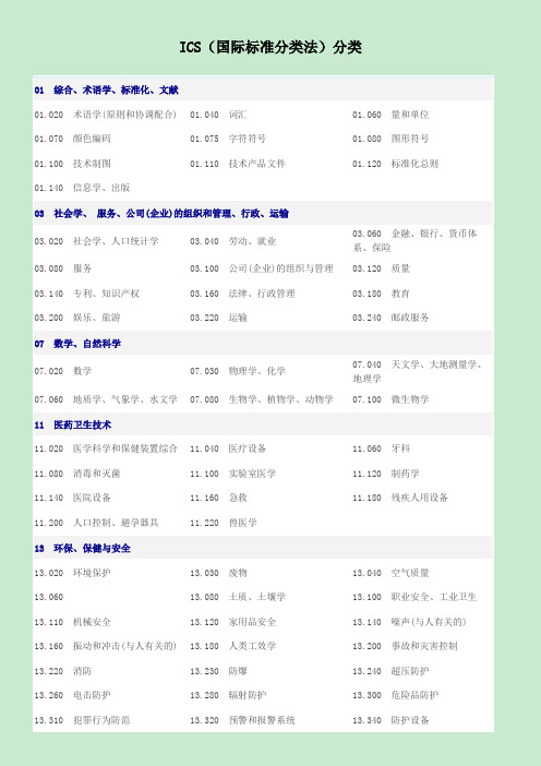
ICS(国际标准分类法)分类01 综合、术语学、标准化、文献01.020 术语学(原则和协调配合)01.040 词汇01.060 量和单位01.070 颜色编码01.075 字符符号01.080 图形符号01.100 技术制图01.110 技术产品文件01.120 标准化总则01.140 信息学、出版03 社会学、服务、公司(企业)的组织和管理、行政、运输03.020 社会学、人口统计学03.040 劳动、就业03.060 金融、银行、货币体系、保险03.080 服务03.100 公司(企业)的组织与管理03.120 质量03.140 专利、知识产权03.160 法律、行政管理03.180 教育03.200 娱乐、旅游03.220 运输03.240 邮政服务07 数学、自然科学07.020 数学07.030 物理学、化学07.040 天文学、大地测量学、地理学07.060 地质学、气象学、水文学07.080 生物学、植物学、动物学07.100 微生物学11 医药卫生技术11.020 医学科学和保健装置综合11.040 医疗设备11.060 牙科11.080 消毒和灭菌11.100 实验室医学11.120 制药学11.140 医院设备11.160 急救11.180 残疾人用设备11.200 人口控制、避孕器具11.220 兽医学13 环保、保健与安全13.020 环境保护13.030 废物13.040 空气质量13.060 13.080 土质、土壤学13.100 职业安全、工业卫生13.110 机械安全13.120 家用品安全13.140 噪声(与人有关的) 13.160 振动和冲击(与人有关的)13.180 人类工效学13.200 事故和灾害控制13.220 消防13.230 防爆13.240 超压防护13.260 电击防护13.280 辐射防护13.300 危险品防护13.310 犯罪行为防范13.320 预警和报警系统13.340 防护设备17 计量学和测量、物理现象17.020 计量学和测量综合17.040 长度和角度测量17.060 体积、质量、密度和粘度的测量17.080 时间、速度、加速度、角速度的测量17.100 力、重力和压力的测量17.120 流体流量的测量17.140 声学和声学测量17.160 振动、冲击和振动测量17.180 光学和光学测量17.200 热力学和温度测量17.220 电学、磁学、电和磁的测量17.240 辐射测量19 试验19.020 试验条件和规程综合19.040 环境试验19.060 机械试验19.080 电工和电子试验19.100 无损检测19.120 粒度分析、筛分21 机械系统和通用件21.020 机器、装置、设备的特性和设计21.040 螺纹21.060 紧固件21.080 铰链、孔眼和其他关节连接件21.100 轴承21.120 轴和联轴器21.140 密封件、密封装置21.160 弹簧21.180 机箱、外壳、其他机械部件21.200 齿轮及齿轮传动21.220 挠性传动和传送21.240 旋转-往复式机构及其部件21.260 润滑系统23 流体系统和通用件23.020 流体存储装置23.040 管道部件和管道23.060 阀门23.080 泵23.100 流体动力系统23.120 通风机、风扇、空调器23.140 压缩机和气动机械23.160 真空技术25 机械制造25.020 制造成型过程25.040 工业自动化系统25.060 机床装置25.080 机床25.100 切削工具25.120 无屑加工设备25.140 手持工具25.160 焊接、钎焊和低温焊25.180 工业炉25.200 热处理25.220 表面处理和涂覆27 能源和热传导工程27.010 能源和热传导工程综合27.020 内燃机27.040 燃气和蒸汽轮机、蒸汽机27.060 燃烧器、锅炉27.070 燃料电池27.080 热泵27.100 电站综合27.120 核能工程27.140 水力工程27.160 太阳能工程27.180 风力发电系统和其27.200 制冷技术27.220 热回收、绝热29 电气工程29.020 电气工程综合29.030 磁性材料29.035 绝缘材料29.040 绝缘流体29.045 半导体材料29.050 导体材料29.060 电线和电缆29.080 绝缘29.100 电工设备元件29.120 电工器件29.140 电灯及有关装置29.160 旋转电机29.180 变压器、电抗器29.200 整流器、转换器、稳压电源29.220 电池和蓄电池29.240 输电网和配电网29.260 特殊工作条件用电气设备29.280 电力牵引设备31 电子学31.020 电子元件综合31.040 电阻器31.060 电容器31.080 半导体器件31.100 电子管31.120 电子显示器件31.140 压电器件和介质器件31.160 滤波器31.180 印制电路和印制电路板31.190 电子器件组件31.200 集成电路、微电子学31.220 电子电信设备用机电零部件31.240 电子设备用机械构件31.260 光电子学、激光设备33 电信、音频和视频技术33.020 电信综合33.030 电信业务、应用33.040 电信系统33.050 电信终端设备33.060 无线通信33.080 综合业务数字网(ISDN) 33.100 电磁兼容性(EMC)33.120 电信设备用部件和附件33.140 电信专用测量设备33.160 音频、视频和视听工程33.170 电视播放和无线电广播33.180 光纤通信33.200 遥控、遥测、遥感35 信息技术、办公机械设备35.020 信息技术(IT)综合35.040 字符集和信息编码35.060 信息技术用语言35.080 软件开发和系统文件35.100 开放系统互连(OSI)35.110 网络35.140 计算机图形技术35.160 微处理机系统35.180 终端和其他外围设备35.200 接口和互连设备35.220 数据存储设备35.240 信息技术应用35.260 办公机械37 成像技术37.020 光学设备37.040 摄影技术37.060 电影37.080 文献成象技术37.100 印制技术39 精密机械、珠宝39.020 精密机械39.040 钟表学39.060 珠宝43 道路车辆工程43.020 道路车辆综合43.040 道路车辆装置43.060 道路车辆内燃机43.080 商用车辆43.100 旅行客车、篷车和轻型挂车43.120 电车43.140 摩托车和机动自行车43.150 自行车43.160 专用汽车43.180 检查、维修和试验设备45 铁路工程45.020 铁路工程综合45.040 铁路工程材料和零件45.060 铁路车辆45.080 钢轨和线路构件45.100 架空索道设备45.120 铁路/架空索道建筑和维护设备47 造船和海上建筑物47.020 船舶和海上建筑物综合47.040 远洋轮47.060 内河船47.080 小型船49 航空器和航天器工程49.020 航空器与航天器综合49.025 航空航天制造用材料49.030 航空航天制造用紧固件49.035 航空航天用零部件49.040 有关航空航天制造用涂覆与有关工艺49.045 结构和结构元件49.050 航空航天发动机和推进系统49.060 航空航天用电气设备与系统49.080 航空航天用流体系统和零部件49.090 机上设备和仪器49.095 客运设备和座舱设备49.100 地面服务和维修设备49.120 货运设备49.140 航天系统和操作装置53 材料储运设备53.020 起重设备53.040 连续搬运设备53.060 工业车辆53.080 储藏设备53.100 土方机械53.120 手工搬运工具55 货物的包装和调运55.020 货物的包装和调运综合55.040 包装材料和辅助物55.060 卷轴、线轴55.080 麻袋、袋子55.100 瓶、罐、瓮55.120 罐、听、管55.130 雾化剂罐55.140 粗腰桶、桶、罐等55.160 箱、盒、板条箱55.180 货运调运55.200 包装机械55.220 堆栈、仓储55.230 发售机和自动售货机59 纺织和皮革技术59.020 纺织工艺59.040 纺织辅助材料59.060 纺织纤维59.080 纺织产品59.100 复合增强材料59.120 纺织机械59.140 皮革技术61 服装工业61.020 服装61.040 帽子、服饰品、衣扣61.060 鞋袜61.080 服装工业用缝纫机和其他设备65 农业65.020 农业和林业65.040 农用建筑物、结构和装置65.060 农业机械、工具和设备65.080 肥料65.100 杀虫剂和其他农用化工产品65.120 饲料65.140 养蜂65.145 狩猎65.150 捕捞和水产养殖65.160 烟草、烟草制品和烟草工业设备67 食品技术67.020 食品工艺67.040 食品综合67.050 食品试验和分析的一般方法67.060 谷物、豆类及其制品67.080 水果、蔬菜及其制品67.100 奶和奶制品67.120 肉、肉制品和其他动物类食品67.140 茶、咖啡、可可67.160 饮料67.180 糖、糖制品、淀粉67.190 巧克力67.200 食用油和脂肪、含油种子67.220 香料和调料、食品添加剂67.230 预包装食品和精制食品67.240 感观分析67.250 与食品接触的物67.260 食品工业厂房和71 化工技术71.020 化工生产71.040 分析化学71.060 无机化学71.080 有机化学71.100 化工产品71.120 化工设备73 采矿和矿产品73.020 采矿和挖掘73.040 煤73.060 金属矿73.080 非金属矿73.100 采矿设备73.120 矿产加工设备75 石油及相关技术75.020 石油和天然气的开采与加工75.040 原油75.060 天然气75.080 石油产品综合75.100 润滑剂、工业油及相关产品75.120 液压液75.140 石蜡、沥青材料和其他石油75.160 燃料75.180 石油和天然气工业设备产品:75.200 石油产品和天然气储运设备77 冶金77.020 金属生产77.040 金属材料试验77.060 金属的腐蚀77.080 黑色金属77.100 铁合金77.120 有色金属77.140 钢铁产品77.150 有色金属产品77.160 粉末冶金77.180 冶金设备79 木材技术79.020 木材加工技术79.040 木材、原木和锯材79.060 木基板材79.080 半成品材79.100 软木和软木制品79.120 木工设备81 玻璃和陶瓷工业81.020 玻璃和陶瓷生产工艺81.040 玻璃81.060 陶瓷81.080 耐火材料81.100 玻璃和陶瓷生产设备83 橡胶和塑料工业83.020 橡胶和塑料工业的生产工艺83.040 橡胶原料和塑料原料83.060 橡胶83.080 塑料83.100 泡沫材料83.120 增强塑料83.140 橡胶和塑料制品83.160 轮胎83.180 粘合剂和胶粘产品83.200 橡胶和塑料工业设备85 造纸技术85.020 纸生产工艺85.040 纸浆85.060 纸和纸板85.080 纸制品85.100 造纸工业设备87 涂料和颜料工业87.020 涂覆工艺87.040 涂料和清漆87.060 涂料配料87.080 墨水、油墨87.100 涂料涂覆设备91 建筑材料和建筑物91.010 建筑工业91.020 自然规划、城市规划91.040 建筑物91.060 建筑构件91.080 建筑物结构91.090 外围建筑物91.100 建筑材料91.120 建筑物的防护91.140 建筑物中的设施91.160 照明91.180 内部装修91.190 建筑附件91.200 施工技术91.220 施工设备93 土木工程93.010 土木工程综合93.020 土方工程、挖掘、地基构造、地下工程93.030 外部污水排放系统93.040 桥梁建筑93.060 隧道建筑93.080 道路工程93.100 铁路建筑93.110 架空索道的建造93.120 飞机场建筑93.140 航道和港口建筑93.160 水利建筑95 军事工程95.020 军事工程、军事物资、武器97 家用和商用设备、文娱、体育97.020 家政97.030 家用电气设备综合97.040 厨房设备97.060 洗衣设备97.080 地板处理设备97.100 家用、商用和工业用加热器具97.120 家用自动控制装置97.130 商店设施97.140 家具97.145 梯子97.150 铺地非织物97.160 家用织物、亚麻织物97.170 人体保健器具97.180 其他家用和商用设备97.190 儿童用器具97.195 艺术和手工艺品97.200 文娱活动设备97.220 运动设备和设施。
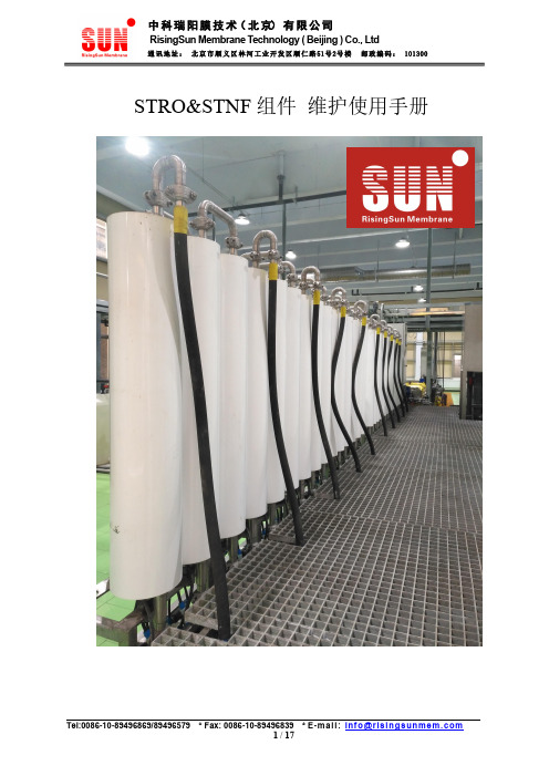
STRO&STNF组件维护使用手册应用:高含盐量、低COD工业废水减量、RO浓缩液再浓缩RO3:2000mg/L NaCl溶液,测试压力15.5bar,回收率15%,温度25℃;RO5:32000mg/L NaCl溶液,测试压力55bar,回收率8%,pH8,温度25℃;NF2:2000mg/L MgSO4溶液,测试压力7bar,回收率15%,温度25℃;2、单支产水量可能在±15%的范围变化,实际产水量根据进水水质的不同会有所差异。
RO5:32000mg/L NaCl溶液,测试压力55bar,回收率8%,pH8,温度25℃;RO6:32000mg/L NaCl溶液,测试压力55bar,回收率8%,pH8,温度25℃;2、单支产水量可能在±15%的范围变化,实际产水量根据进水水质的不同会有所差异;3、***120bar使用料液温度<30℃;RO3:2000mg/L NaCl溶液,测试压力15.5bar,回收率15%,温度25℃;RO5、RO6:32000mg/L NaCl溶液,测试压力55bar,回收率8%,pH8,温度25℃;2、单支产水量可能在±15%的范围变化,实际产水量根据进水水质的不同会有所差异;3、***120bar使用料液温度<30℃;STRO/NF组件必须按照清洗说明的规程进行,否则STRO/NF组件的性能会受影响,膜元件的使用寿命会降低。
须保持组件上的转矩负载,建议扭矩为30-35N.M;否则可能会影响膜元件的密封及对两端法兰盘造成损害。
动力学设计大大降低了其它类型逆渗透组件中常见的结垢问题,且该组件易于维护。
该组件的最佳脱盐性能限定在零上25摄氏度,如果是废水则为零上15摄氏度。
组件可以在零上40摄氏度下持续运行,在50摄氏度下可以短时间(30分钟内)运行。
膜组件尺寸:组件完全部件编号:以下对流经组件的液体描述没有采取缩尺图,而是采用了示意图的形式。
The ICS650-01 is a low cost, low jitter, high performance clock synthesizer for system peripheral applications. Using analog/digital
Phase-Locked Loop (PLL) techniques, the device accepts a parallel resonant 14.31818 MHz crystal input to produce up to eight output clocks. The device provides clocks for PCI, SCSI, Fast
Ethernet, Ethernet, USB, and AC97. The user can select one of three USB frequencies, and also one of three AC97 audio frequencies. The OE pin puts all outputs into a high impedance state for board level testing. All frequencies are generated with less than one ppm error, meeting the demands of SCSI and Ethernet clocking.
The ICS650 can be mask customized to produce any frequencies from 1 to 150 MHz.
Block Diagram
Description
Features
• Packaged in 20 pin tiny SSOP (QSOP)• Operating VDD of 3.3V or 5V
• Less than one ppm synthesis error in all clocks • Inexpensive 14.31818 MHz crystal or clock input • Provides Ethernet and Fast Ethernet clocks • Provides SCSI clocks • Provides PCI clocks
• Selectable AC97 audio clock • Selectable USB clock
• OE pin tri-states the outputs for testing • Selectable frequencies on three clocks • Duty cycle of 40/60
• Advanced, low power CMOS process
USB Clock Audio Clock Processor Clocks (Fast Ethernet, SCSI, PCI )14.31818 MHz
20 MHz Output Enable (all outputs)
Key: I = Input; XO/XI = crystal connections; O = output; P = power supply connection
VDD UCLK X2VDD 20 pin (150 mil) SSOP PCLK4
PSEL0X1/ICLK USEL
PCLK2PSEL1PCLK3PCLK1OE
ACLK 20M GND VDD
14.318M GND ASEL Processor Clock (MHz)
0 = connect directly to ground, 1 = connect directly to VDD, M=leave unconnected (floating)
Pin Assignment
Electrical Specifications
Notes: 1. Stresses beyond those listed under Absolute Maximum Ratings could cause permanent damage to the device. Prolonged exposure to levels above the operating limits but below the Absolute Maximums may affect device reliability.
2. With all clocks at highest frequencies.
External Components
The ICS650 requires a minimum number of external components for proper operation. Decoupling capacitors of 0.1µF should be connected between VDD and GND (on pins 4 and 6, and pins 16 and 14), as close to the chip as possible. A series termination resistor of 33Ω may be used for each clock output. The 14.31818 MHz crystal must be connected as close to the chip as possible. The crystal should be a fundamental mode, parallel resonant, 30ppm or better (to meet the Ethernet specs). Crystal capacitors should be connected from pins X1 to ground and X2 to ground. The value of these capacitors is given by the following equation, where C L is the crystal load capacitance: Crystal caps (pF) = (C L-12) x 2. So for a crystal with 16pF load capacitance, two 8pF caps should be used. If a clock input is used, drive it into X1
and leave X2 unconnected.
Package Outline and Package Dimensions
While the information presented herein has been checked for both accuracy and reliability, Integrated Circuit Systems, Incorporated (ICS) assumes no responsibility for either its use or for the infringement of any patents or other rights of third parties, which would result from its use. No other circuits, patents, or licenses are implied. This product is intended for use in normal commercial applications. Any other applications such as those requiring extended temperature range, high reliability, or other extraordinary environmental requirements are not recommended without additional processing by ICS. ICS reserves the right to change any circuitry or specifications without notice. ICS does not authorize or warrant any ICS product for use in life support devices or critical medical instruments.。