Lagged strain of laminates in RC beams strengthened with fiber-reinforced polymer
- 格式:pdf
- 大小:206.61 KB
- 文档页数:5
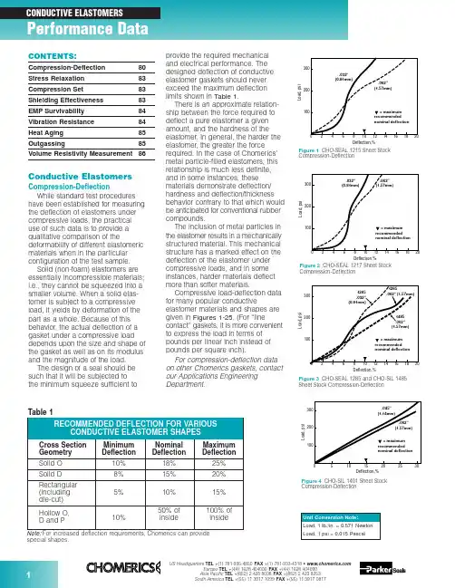
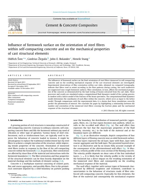
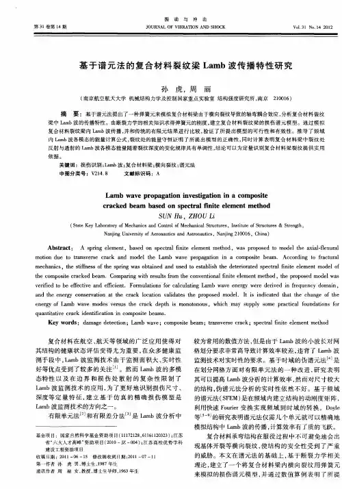
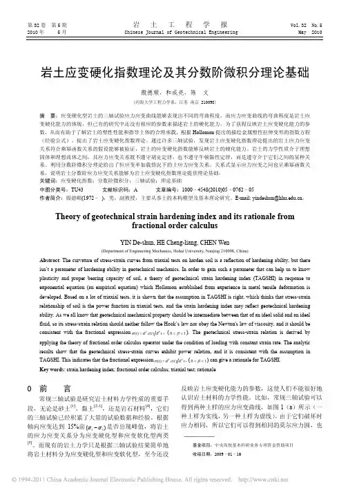
Figure 3CHO-SEAL 1285 and CHO-SIL 1485Sheet Stock Compression-DeflectionCompression-Deflectionspecial shapes.Conductive ElastomersCompression-DeflectionWhile standard test procedures have been established for measuring the deflection of elastomers under compressive loads, the practical use of such data is to provide a qualitative comparison of thedeformability of different elastomeric materials when in the particular configuration of the test sample.Solid (non-foam) elastomers are essentially incompressible materials;i.e., they cannot be squeezed into a smaller volume. When a solid elas-tomer is subject to a compressive load, it yields by deformation of the part as a whole. Because of this behavior, the actual deflection of a gasket under a compressive load depends upon the size and shape of the gasket as well as on its modulus and the magnitude of the load.The design of a seal should be such that it will be subjected to the minimum squeeze sufficient toprovide the required mechanical and electrical performance. The designed deflection of conductive elastomer gaskets should never exceed the maximum deflection limits shown in Table 1.There is an approximate relation-ship between the force required to deflect a pure elastomer a given amount, and the hardness of the elastomer. In general, the harder the elastomer, the greater the force required. In the case of Chomerics’metal particle-filled elastomers, this relationship is much less definite,and in some instances, these materials demonstrate deflection/hardness and deflection/thickness behavior contrary to that which would be anticipated for conventional rubber compounds.The inclusion of metal particles in the elastomer results in a mechanically structured material. This mechanical structure has a marked effect on the deflection of the elastomer under compressive loads, and in some instances, harder materials deflect more than softer materials.Compressive load-deflection data for many popular conductiveelastomer materials and shapes are given in Figures 1-25. (For “linecontact” gaskets, it is more convenient to express the load in terms of pounds per linear inch instead of pounds per square inch).For compression-deflection data on other Chomerics gaskets, contact our Applications Engineering Department.Compression-DeflectionCompression-DeflectionCONTENTS:Compression-Deflection 80Stress Relaxation 83Compression Set 83Shielding Effectiveness 83EMP Survivability 84Vibration Resistance 84Heat Aging 85Outgassing85Volume Resistivity Measurement86Figure 80.125 in. (3.18 mm) Dia. O-Strip Compression-DeflectionDeflection,%Compression-DeflectionCompression-DeflectionL o a d , l b ./i n c hDeflection, %Figure 210.156 in. (3.96 mm) High Hollow D-Strip Compression-DeflectionL o a d , l b ./i n c hDeflection, %Figure 220.312 in. (7.92 mm) High Hollow D-Strip Compression-DeflectionFigure 200.250 in. (6.35 mm) Dia. Hollow O-Strip Compression-DeflectionL o a d , l b ./i n c hDeflection, %L o a d , l b ./i n c hDeflection, %Figure 230.250 in. (6.35 mm) Dia. Hollow P-Strip Compression-DeflectionFigure 240.360 in. (9.14 mm) Dia. Hollow P-Strip Compression-DeflectionL o a d , l b ./i n c hDeflection, %L o a d , l b ./i n c hDeflection,%Figure 190.156 in. (3.96 mm) Dia. Hollow O-Strip Compression-DeflectionL o a d , l b ./i n c hDeflection, %Figure 170.250 in. (6.35 mm) Wide Rectangular Strip Compression-Deflection0.40.81.20.20.61.0C o m p r e s s i o n F o r c e (l b /i n )00.5 1.50.10.2Deflection (inch)1356P/N 10-09-W864-XXXXFigure 250.410 in. (10.41 mm) High V-Strip Compression-DeflectionStress RelaxationAs important as Compression Set and Compression-Deflection, is the Stress Relaxation characteristic of a gasket.If a rubber is subject to a com-pressive load, it will deflect. There is a stress/strain relationship, which for rubbers is generally non-linear except for very small deflections.After the load is applied, a stress decay occurs within the polymer resulting from the internal rearrange-ment of the molecular structure. An approximate rule is that the relaxed stress for cured silicone will finally settle at 70 to 75 percent of the initial stress.There are two ways in which a rubber gasket can be loaded to a desired value. One way is to load it to a point, let it relax, and reapply the load to restore the original stress. The next time it will relax, but not so much.If this is repeated a sufficient number of times, the correct static load on the gasket will reach equilibrium.A more practical way to reach the design value of stress is to load the gasket to 125 percent of its final design value, so that after the relax-ation process is completed the gasket will settle to 100 percent of the design load. This is very reproducible.Figure 26shows a typical stress relaxation curve for Chomerics’conductive elastomers.Compression SetWhen any rubber is deformedfor a period of time, some of the defor-mation is retained permanently even after the load is removed. The amount of permanent deformation, asmeasured by ASTM D395, is termed “Compression Set.” Compression set is measured under conditions of constant deflection (ASTM D395Method B) and is normally expressed as a percentage of the initialdeflection, not as a percentage of the initial height.For gaskets that are used once, or where the gasket/flange periphery relationship is constant (such as a door gasket), compression set is of minor significance if the original load condition and the service temperature are within the design limitations of the gasket material.For gaskets that are randomlyreseated one or more times in normal service life, it is important that the maximum change in gasket thickness does not exceed twice the maximum mismatch between the opposing mating surfaces.Shielding EffectivenessMost shielding effectiveness data given in Table 3 of the Conductive Elastomer section (pages 32-34) is based on a MIL-G-83528B testmethod, with a 24 in. x 24 in. aperture in a rigid enclosure wall and about 100 psi on the gasket. It is a valid and useful way of comparing variousgasket materials, but does not reflect the shielding effectiveness one can expect at seams of typical enclosures.CHO-TM-TP08 is a modified version of the MIL test that provides typical values achieved in actual applications.Since many factors will affect the actual shielding effectiveness of anenclosure seam (flange design,stiffness, flatness, surface resistivity,fastener spacing, enclosuredimensions, closure force, etc.), the only way to determine shielding effectiveness for real enclosures is to test them.Figures 28and 29provide dataon shielding effectiveness for actualFigure 27Formula for Calculation of Compression Setenclosures. The data in Figure 28shows the difference in attenuation between a shelter door closed with no gasket and the same door closed against a CHO-SEAL 1215 hollow D-strip gasket. Instead of single data points at each frequency tested, a range of data is shown for eachfrequency, representing the worst and best readings measured at many points around the door. Figure 29 shows the effects of closure force on shielding effectiveness of an enclosure tested at high frequencies (1-40 GHz) using CHO-SEAL 1215 solid D-strip gaskets.In order to establish reasonable upper limits on gasket resistivity, it is necessary to understand the rela-tionship between flange interface resistance and EMI leakage through the flange. Figure 30presents this relationship for an aluminum enclosure 3 in. x 3 in. x 4 in. deep, measured at 700 MHz. Die-cut gaskets 0.144 in.wide by 0.062 in. thick, in a wide range of resistivities, were clamped between the gold-plated flanges of thisenclosure. Simultaneous measure-ments of flange interface resistance (all attributable to the gaskets) versus RF leakage through the seamproduced a classic S-shaped curve.For the gasket configuration used in this test, the dramatic change in shielding effectiveness occursbetween gasket volume resistivities of 0.01 and 0.4 ohm-cm. Since real enclosures do not have gold-plated flanges, but rather have surfacefinishes (such as MIL-C-5541 Class 3chromate conversion coatings) which also increase in resistance over time, it is recommended that gasket volume resistivity be specified at 0.01 ohm-cm max. for the life of the equipment.Frequency, HzA t t e n u a t i o n (dB )Figure 28Shielding Effectiveness of a Shelter Door Gasket (14 kHz to 10 GHz)kA/inch of gasket (peak-to-peak).Pure silver (1224) and silver-plated-aluminum filled (1285) gaskets have less current carrying capability than silver-plated-copper materials, but are generally acceptable for EMP hardened systems (depending on specific EMP threat levels, gasket cross section dimensions, etc.).Vibration ResistanceCertain conductive elastomers are electrically stable during aircraft-level vibration environments, while others are not. The key factor which deter-mines vibration resistance is theshape and surface texture of the filler particles. Smooth, spherical fillers (such as those used in silver-plated-Figure 32Scanning Electron Microscopy Illustrates EMP Damage Mechanism for Silver/Glass ElastomersL e a k a g e (d B )Vibration (g)Figure 33Effects of Vibration on Shielding Effectiveness of Conductive Elastomer GasketsEMP SurvivabilityIn order for an enclosure to continue providing EMI isolationduring and after an EMP environment,the conductive gaskets at joints and seams must be capable of carrying EMP-induced current pulses without losing their conductivity. Figure 31shows the EMP current response of various types of conductive elastomer gaskets. Note that gaskets based on silver-plated-glass fillers (1350)become nonconductive at low levels of EMP current, and should therefore not be used when EMP is a design consideration. Figure 32is an electron microscope photo which clearly shows the damage mechanism.Silver-plated-copper filled (1215)gaskets have the highest resistance to EMP type currents, showing no loss of conductivity even at 2.50102030405060Shielding Degradation, dBIn t e r f a c e R e s i s t a n c e , m i l l i o h m sFigure 30Interface Resistance vs. Shielding Degradation at a Flange Jointglass materials) tend to move apart during vibration, leading to dramatic increases in resistance and loss of shielding effectiveness (although they normally recover their initial properties after the vibration has ended). Rough, less spherical particles resist vibration with very little electrical degradation. Figure 33shows the effects of vibration on three types of conductive gaskets.Although Chomerics’ silver-plated-copper filled 1215 gasket, with rough,irregular particle agglomerations,exhibits excellent stability during vibration, users of conductive elastomers should be aware that smooth, spherical silver-plated-copper fillers can be almost asunstable as silver-plated-glass fillers.Frequency, GHzA t t e n u a t i o n (dB )Figure 29Effect of Closure Force on Shielding Effectiveness (1 GHz to 40 GHz)Heat AgingThe primary aging mechanism which affects electrical stability of conductive elastomers is the oxidation of filler particles. Formaterials based on pure silver fillers,particle oxidation is not generally a problem because the oxide of silver is relatively soft and reasonably conductive. If the filler particles are non-noble (such as copper, nickel,aluminum, etc.) they will oxidize readily over time and become nonconductive. Even silver-plated base metal powders, such as silver-V o l u m e R e s i s t i v i t y (o h m -c m )Hours at 150°C (Solid Line)Hours at 125°C (Dotted Line)Figure 34Typical heat aging characteristics of Chomerics’ plated-powder-filled conductiveelastomers. Flanged 1000-hr test recommended for qualification. Unflanged 48-hr. test recommended for QC acceptance.plated-copper or silver-plated-aluminum will become non-conductive over time if the plating is not done properly (or if other processingvariables are not properly controlled).These are generally batch control problems, with each batch being potentially good or bad.The most reliable method of predicting whether a batch will be electrically stable is to promote the rate at which poorly plated or processed particles will oxidize, by heat aging in an air circulating oven.For qualification, 1000 hours (42 days)at maximum rated use temperature (with the gasket sample deflected 7-10% between flanges) is the recommended heat aging test for accelerating the effects of long-term aging at normal ambient tempera-tures. A quicker heat aging test,which correlates well with the 1000hour test and is useful for QC acceptance testing, involves a 48hour/150°C oven bake with thegasket sample on an open wire-grid tray (rather than being clamped between flanges). Figure 34shows typical data for volume resistivity versus time for each of these tests.Note:It is essential that no source of free sulfur be placed in the aging oven, as it will cause the material to degrade electrically and mask any oxidation aging tendencies. Common sources of sulfur are neoprenes,most cardboards and other paper products.OutgassingMany spacecraft specifications require that nonmetallic components be virtually free of volatile residues which might outgas in the hard vacuum environment of space. The standard test method for determining outgassing behavior is ASTM E595-93, which provides for measurement of total mass loss (TML) and collected volatile condensable materials (CVCM) in a vacuum environment. Data for a number of Chomerics conductive elastomers,based on ASTM E595-93 testing done by NASA Goddard SpaceflightCenter, is presented in Table 2. The normal specification limits or guide-lines on outgassing for NASA applications are 1% TML max.,and 0.1% CVCM max.。
Influence of formwork surface on the orientation of steel fibres within self-compacting concrete and on the mechanical properties of cast structuralelementsOldrˇich Švec a ,⇑,Giedrius Z ˇirgulis b ,John E.Bolander c ,Henrik Stang a aDepartment of Civil Engineering,Technical University of Denmark,2800Kgs.Lyngby,DenmarkbDepartment of Structural Engineering,Norwegian University of Science and Technology,7491Trondheim,Norway cDepartment of Civil and Environmental Engineering,University of California,Davis,CA 95616,USAa r t i c l e i n f o Article history:Received 26April 2013Received in revised form 29September 2013Accepted 5December 2013Available online 16December 2013Keywords:Fibre reinforced self-compacting concrete Fibre orientationComputed tomography Numerical simulation Fracturea b s t r a c tThe influences of formwork surface on the final orientation of steel fibres immersed in self-compacting concrete and on the resulting mechanical response of the cast structural elements are investigated.Experimental observations of fibre orientation within cast slabs,obtained via computed tomography,indicate that fibres tend to orient according to the flow patterns during casting,but such tendencies are suppressed near rough formwork surfaces.Fibre orientation,in turn,affects the mechanical proper-ties of the concrete as demonstrated by the load testing of beams extracted from the cast slabs.These processes and results are simulated using a computational fluid dynamics model of the casting process,in tandem with a lattice model of the fracture of the beam specimens.The computational fluid dynamics model determines the coordinates of each fibre within the concrete,which serve as input to the lattice model.Through comparisons with the experimental data,it is shown that these simulations correctly predict the phenomena of interest.We conclude the paper by highlighting a relationship between the number and orientation of the immersed steel fibres crossing the fracture plane and the mechanical response of the structural elements.Ó2013Elsevier Ltd.All rights reserved.1.IntroductionA growing portion of civil structures is nowadays constructed of self-compacting concrete.Contrary to ordinary concrete,self-com-pacting concrete flows and fills the formwork without any need of vibration or other type of agitation.Various forms of steel rein-forcement,such as reinforcement bars,are typically used to im-prove the behaviour of concrete loaded in tension.It might be advantageous to replace the traditional reinforcement bars by steel fibres to achieve a simple execution of the structure,while improv-ing tensile properties of the concrete.Orientation of immersed steel fibres evolve in response to the flow of the self-compacting concrete within the formwork [1,2].In particular,fibre orientations are affected by shear flow of the material and interactions with the formwork boundaries [3].The fibre orientation and thus properties of the structural elements can be then heavily dependent on the material rheology and the methods of element casting [1,4].Concrete is a multiphase material consisting of cement paste,fine and coarse aggregates,and possibly fibres.Due to the geomet-rical constraint imposed by a solid boundary on particle packing near the boundary,the distribution of immersed particles (aggre-gates,fibres,etc.)in that region becomes non-uniform,which re-sults in the so-called wall effect (Fig.1a).The wall effect thus expresses the fact that the macroscopic properties of the fluid (density,viscosity,etc.)in the bulk of the material and at the boundary layers are different.Fig.1a ,as an illustrative example,depicts composition of four different layers of flowing concrete near an oiled formwork surface.The four layers represent the oil layer,layer with fines,layer with coarser aggregates and the bulk layer.The presented layered struc-ture is an illustrative and by no means fully accurate example of the consequence of the aforementioned wall effect.Fig.1b illus-trates a velocity profile of the cross-section of the flowing concrete.The velocity profile depends on shear rates of the four individuallayers,_c1À4.It is likely that the velocity profile in the vicinity of the formwork has a direct impact on the resulting orientation of the immersed steel fibres and consequently on the resulting mechanical response of the material.The wall effect,together with various types of formwork char-acterised by different roughness and treatment,contribute to uncertainties in the behaviour of structures made of fibre rein-forced self-compacting concrete.Especially for thin elements,the flow of the material and consequently the mechanical response0958-9465/$-see front matter Ó2013Elsevier Ltd.All rights reserved./10.1016/j.cemconcomp.2013.12.002Corresponding author.E-mail address:oldrich.svec@ (O.Švec).of the elements is significantly influenced by the formwork–fluid interaction.In the field of fibre reinforced self-compacting concrete,several authors discuss the influence of casting process on the orientation of steel fibres [3,5–7].Others study the impact of fibre orientation on the mechanical response of the structural elements [1,8–10].Jacobsen et al.[11]addresses the impact of the formwork surface on the pumpability of an ordinary concrete.The presented paper merges all the problems into one by study-ing the influence of the formwork surface on the flow pattern of steel fibre reinforced self-compacting concrete close to thework.The paper further studies the influence of the final tion of steel fibres on the resulting mechanical properties of material.The study is carried out through the combined use physical experiments and numerical modelling.The study was performed by means of tomographic imaging of specimens cast with fibre reinforced self-compacting and by means of three-and four-point bending tests of cut from the slabs.The numerical study was conducted by of two distinct numerical simulations developed by the (1)a computational fluid dynamics based procedure to simulatebre movement during the casting process,including interactions at the formwork boundaries and (2)a lattice model material elasticity and fracture,including the explicit tion of individual fibres within the specimen volumes.Fibre dinates determined through the computational fluid based simulation served as direct input to the lattice of the flexural test specimens.Materials and methods of the presented study are fully de-scribed in Section 2.The casting process and the data analysis pro-cess of the experimental study are explained in Section 2.1.The two distinct numerical simulations are introduced in Section 2.2.Section 3presents all the experimentally and numerically obtained results related to the orientation of steel fibres and related to the mechanical properties of the material.The aforementioned results are linked together in Section 3.3.Discussion of the results is pro-vided in Section 4.Section 5concludes the article.2.Materials and methodsThe following subsections describe experiments that were con-ducted to verify the hypothesis that formwork surface can influ-ence the orientation of fibres immersed in self-compacting concrete and,consequently,the mechanical response of the struc-ture.The numerical simulations,which were used to strengthen and complement the experimental observations,are also briefly introduced.2.1.ExperimentsSix slabs of fibre reinforced self-compacting concrete were cast using formwork of three different surface types.The following sub-sections describe the casting process of the slabs,methods for quantifying the orientations of fibres immersed in the slabs,and the subsequent mechanical testing of beam specimens cut from the slabs.2.1.1.Mixture design and casting processSix slabs of dimensions 1.2m Â1.2m Â0.15m were cast of fi-bre reinforced self-compacting concrete.The casting process was conducted from a rubber pipe inlet positioned near one of the cor-ners of the slab (Fig.2).The point of discharge was located at 0.2m above the base of the slab.Mixture design of the self-compacting concrete was:cement =388kg =m 3,silica fume =19:4kg =m 3,natural sand ð0—8mm Þ¼1182kg =m 3,crushed stone ð8—16mm Þ¼570kg =m 3,super plasti-ciser =4:66kg =m 3and air entrainer (1:7)=0:97kg =m 3.The water ce-ment ratio was 0.505.At the time of mixing,the fine and coarse aggregates were in the saturated-surface-dry condition.Hooked end steel fibres (Bekaert Dramix RL 80/60BN)were gradually added to the self-compacting concrete during the mixing process.The fibre volume ratio was 0.5%,corresponding to 40kg/m 3.The fibre length and the fibre diameter were 60mm and 0.75mm,respectively.Density of the steel fibres was 7850kg/m 3.Three different formwork surfaces were employed in the Supplementary video.The video a shows casting process of steel fibre self-compacting concrete into a formwork of three different surface roughnesses.O.Švec et al./Cement &Concrete Composites 50(2014)60–7261which shows the casting of the fibre reinforced self-compact-ing concrete into the glue-laminated plywood formwork,ordin-ary plywood formwork and into the glued-sand plywood formwork.Rheology of the fresh fibre reinforced self-compacting concrete was evaluated during the casting process by means of the stan-dardized slump flow test according to EN 12350-2.Spread of the slump was measured and read 620mm.Rheological parameters,following a Bingham plastic rheological model,were obtained by means of 4C-Rheometer [13].Yield stress and plastic viscosity of the fibre reinforced self-compacting concrete were estimated to be 22Pa and 75Pa s,respectively.The measured density and air content of the fresh concrete were 2318kg/m 3and 3.5%,respectively.After casting,the slabs were covered with cloth saturated with water.The slabs were then sealed within a polyethylene film and left to harden for a period of 28days at ambient temperatures.In total six beam specimens of dimensions 0.6m Â0.15m Â0.15m were then cut out from each of the slabs,as indicated by the 1red and green prisms in Fig.4.Orientation of the steel fibres present in the beams specimens was studied by means of the computed tomography and subse-quent image analysis.The resulting mechanical response of the beam specimens was studied by means of the three-and four-point bending tests.puted tomography and image analysisComputed Tomography (CT)is an advanced radiographic tech-nique for obtaining 3D images of the internal structure of an ele-ment.The method has been among others widely used in the field of steel fibre reinforced concrete [1,14–16].The CT and subse-quent image analyses were employed to obtain a 3D representa-tion of the steel fibres located in the beam specimens.The 3D representation was subsequently approximated by a set of 3D ori-entation tensors [17].We used a former medical CT scanner,Siemens Somatom Sen-sation 4,to scan three beam specimens out of each slab.The three scanned beam specimens are depicted in Fig.4as red prisms.Sequential spine routine of the medical CT scanner was employed to interpret approximately 600successive slices normal to the x axis (Fig.4).A typical slice image produced by the CT scanner is presented in Fig.5.The red regions in Fig.5b are the voxels with maximum brightness.The red regions were obtained by threshold-ing the image.The zone marked by the green rectangle in Fig.5b reveals that not only fibres but also parts of aggregates are marked in red.This is caused by a relatively low tube voltage of the medical CT scanner and results in a more complicated image analysis.An open-source application Fiji 2was used to crop,threshold and skeletonise the sequence of the approximately 600successive slice images.The skeletonisation technique of the Fiji application output-ted a skeleton,i.e.a large set of 3D line segments located in space.Fig.6as an example shows a small part of the skeleton.Red region in Fig.6shows 3D line segments that were probably created by skeletonising aggregates depicted in Fig.5b.Fig.6re-veals that although the majority of the 3D line segments represent individual parts of steel fibres,some of the 3D line segments rep-resent other concrete constituents such as aggregates.The primary interest of the paper is to study orientation of steel fibres.The 3D line segments were therefore converted into a set of second-order orientation tensors [17].The second-order tensors can be visual-ised by means of 3D ellipsoids in space or by means of 2D ellipses in plane.All the CT scanned beam specimens were volumetrically split into a series of cubic regions (see Fig.7b for a 2D projection).Sec-ond-order orientation tensors were computed for all the 3D line segments located in each of the cubic regions.Fig.7c illustrates the second-order tensors by projecting the 3D orientation ellip-soids into 2D orientation ellipses.The second-order orientation tensors can be computed as [17]:a ij ¼1tPLp x p xP Lp x p y P Lp x p zPLp y p yP Lp y p z sym :PLp z p z264375;ð1Þwhere the summation is taken through all the line segments located in the cubic region of interest.Values of p x ;p y and p z are compo-nents of the normalised vector pointing in the direction of the indi-vidual line segments located in the cubic region of interest.Valueofsurface views of three different formwork types.(a)Glue-laminated plywood.(b)Ordinary plywood.(c)Glued-sand1For interpretation of colour in Figs.4–6,the reader is referred to the web version of this article.2http://fiji.sc/.L is the length of the individual line segments length of the line segments located in the L t ¼P L .The summation of the main diagonal of must be equal to unity,i.e.,a 1;1þa 2;2þa directions of the axes of the orientation ellipsoids eigenvalues and eigenvectors of the second-order sors,respectively.Results of the computed are presented in Section 3.1.1.2.1.3.Three-and four-point bending testsAll the six beam specimens indicated obtain their mechanical response in flexure.depicted by green prisms in Fig.4were bending according to the Norwegian sawn After the CT scanning,as presented in specimens depicted as red prisms in Fig.vide a notch at mid-span and tested according to EN 14651.During the test,the beam specimens were oriented in the casting direction,such that the tensile face was the bottom cast surface of the beam which EN 14651.Fig.8depicts a typical fracture of bending test.The degree of planarity of that these surface views of fracture represent pattern well.Fig.5.(a)A typical slice image of the scanned beam specimens.(b)Regions with the maximum brightness.6.Result of the skeletonisation technique of the CT images.Black lines are the individual 3D line segments.(a)(b)(c)7.Process for obtaining the second-order orientation tensors:(a)skeleton image of fibres within beam specimen;(b)volumetric discretization into cubic regions;and (c)second-order tensor representation of fibre orientation within each 8.A typical frontal view of the fractured beam specimens.Top:three-point bending test.Bottom:four-point bending test.CMOD.For the four-point bending tests,load and respective mid-span deflections of the beam specimens,d m,were recorded.For the purpose of comparing results of the different types of beam tests,an effective CMOD for the case of four-point bending was computed based on[18]ascmod4pt¼4h d ml4pt;ð2Þwhere hð¼0:15mÞis the height of the beam specimen and l4ptð¼0:45mÞis the distance between the beam supports.In the case of the three-point bending tests,theflexural stresses of beam specimens were computed as[19]r3pt¼3Fl3pt2bh2sp;ð3Þwhere bð¼0:15mÞis the width of the beam specimen and h spð¼0:125mÞis the distance between tip of the notch and top of cross section[20].Value of l3ptð¼0:5mÞstands for the span between the beam supports.In the case of the four-point bending tests,theflexural stress of a beam specimen was computed asr4pt¼Fl4ptbh:ð4ÞResults of the three-and four-point bending tests are presented in Section3.2.1.2.1.4.Fibre count local to the fracture planeSection2.1.2described the process of scanning of the beam specimens depicted by red prisms in Fig.4.For each3D image of the beam specimens produced by CT scanning,we selected the im-age slice located closest to the fracture plane.The number of steel fibres crossing the fracture plane was estimated by manually counting thefibres visible on the slice images similarly to [10,?,21,22].In addition,all the beam specimens tested by the three-and four-point bending tests were cut in the vicinity of the main crack. The cut plane was polished and the number of steelfibres visible at the cut plane was manually counted.The number of steelfibres crossing the fracture plane or the cut plane was related to theflex-ural stresses of the individual beam specimens at an arbitrarily chosen crack mouth opening displacement,as will be presented in Section3.3.2.2.Numerical simulationsTwo distinct types of numerical simulation were run to strengthen the experimental observations and to shed light on the phenomenological processes observed in the experiments. Thefirst type simulates theflow of thefibre reinforced self-com-pacting ingfibre coordinate data from theflow simu-lations,the second type simulates the fracture behaviour of the hardenedfibre reinforced self-compacting concrete.2.2.1.Numerical simulation offlowIn recent years there have been growing fundamental and prac-tical interests in numerically simulating theflow of concrete mate-rials,includingfibre reinforced concrete[23].Roussel et al.[24] review the advantages and disadvantages of several strategies for simulating concreteflow.We have developed a numerical frame-work capable of predictingflow of explicitly represented rigid par-ticles immersed in the free surfaceflow of a homogeneous non-Newtonianfluid,such as fresh concrete.One of the primary goals of the numerical framework has been to quantitatively predict the distribution and orientation of the steelfibres immersed in the self-compacting concrete during casting.The numerical frame-work is explained in detail in[25].We discussed the implementa-tion of the immersed rigidfibres into the framework in[26].The ability of the numerical framework to properly simulate various formwork surfaces was introduced in[27].Fig.9presents a3D view of the numerical simulation of slab casting at an intermediate step.The numerical simulation was run with the same physical input parameters(fluid density,yield stress plastic viscosity,fibre type,etc.)as presented in Section 2.1.1.As a possibility for future research,the determination of in-put parameters could be supported by predictive models[28,29]. The numerical framework is devoid of any non-physical input parameters.The self-compacting concrete was modelled as a free surfaceflow of a homogeneous Bingham plasticfluid.The steel fibres were modelled as thin rigid cylinders immersed in the homogeneousfluid.The steelfibres were modelled explicitly,one by one,including various features of the numerical framework such as the two-way coupled interaction between thefluid and thefibres,plastic collisions among thefibres or plastic collisions of thefibres with the formwork.The formwork was modelled as Navier’s slip boundary condition of a specific Navier’s slip length [27].Thefluid domain was discretized as1cm=1discrete unit.In total three different numerical simulations were run differen-tiated by the type of the formwork surface used in the numerical simulation.The three different Navier’s slip lengths were then equal to0cm,8cm and1.Each numerical simulation was run in parallel on25computer cores and lasted approximately4days.The peak number of explic-itly simulated steelfibres was approximately41,000.Results of the numerical simulation offlow are presented in Section3.1.2.2.2.2.Numerical simulation of fracture behaviourA lattice-type model is used to simulate the fracture behaviour of thefibre-reinforced concrete.Both the matrix andfibre element formulations are based on the concept of a rigid-body-spring mod-el,as described in previous publications[30–32].The concrete ma-trix is assumed to be homogeneous and exhibit bilinear softening after fracture.Material disorder is solely due to the presence of the short-fibre reinforcement,which is explicitly represented within the model framework.Domain discretization is based on the Delaunay/Voronoi tessellation of a set of nodes[33].Discretiza-tion of thefibre-reinforced concrete specimens is presented in Fig.10a.Stiffness contributions of thefibres before concrete cracking are derived from elastic shear lag theory.After concrete cracking,fibre contributions to strength and stiffness across the open crack ac-count for debonding and slip at thefibre–matrix interface.The ef-fect of the hooked end of thefibres was approximated as a frictional force,distributed uniformly over thefibre embedded length.The pullout behaviour of individualfibres was modified to account for snubbing effect and the potential for matrix spalling whenfibres are lowly inclined to the fracture plane[34].The lattice model was used to simulate fracture behaviour of each of the four-point bend tests(B1a,B2a,and B3a)for the case of glue-laminated plywood as formwork.This case exhibited the largest variation in load–displacement behaviour with respect to beam position in the slab.Thefinal positions of the steelfibres within the cast slab spec-imens were supplied by the aforementioned numerical simulations offlow.Thereafter,the slabs were sectioned to produce models of the beam specimens,as shown in Fig.4,in a way that mimicked the physical cutting process.Fibres intersecting the cut planes were cut at the point of intersection,retaining the portion inside the beam volume.Fig.10b as an example illustrates steelfibres present in one of the tested beam specimens.64O.Švec et al./Cement&Concrete Composites50(2014)60–72Fracture of the beam specimens was restricted to occur along the central plane within the beam span(see Fig.10).This simplifi-cation allows for the grading of nodal point density in the vicinity of the crack plane to reduce computational expense.As discussed later,however,restricting the location of cracking can affect the mechanical response of the beams.Tensile strength of the matrix and the pullout resistance of individualfibres were adjusted to achieve rough agreement between the load–displacement curve of the model and that of the B1a specimen.The following settings were used as a result of the calibration process:uniaxial tensile strength r t¼2MPa; r1¼r t=4;w1¼0:05mm;traction-free crack opening displace-ment w c¼0:3mm;and frictional resistance s f¼4MPa[31].The same parameter set was then used for the simulations of specimens B2a and B3a.The results for specimens B2a and B3a can be therefore viewed as predictive simulations.The assumptions made herein,including thefitting of param-eter values for the B1a specimen,were deemed reasonable for achieving the primary goal of the fracture simulations,which is to demonstrate the effects offibre distribution on the fracture behaviour of theflexural specimens.Results of the numerical simulation of fracture behaviour are presented in Section3.2.2.3.ResultsThis section presents results obtained by CT scanning and by the three-and four-point bending tests.These experimental results are then compared to results obtained from their respective numerical simulations.3.1.Fibre orientationThe following two subsections study the average planar(x–y) orientation of the steelfibres by means of the second-order orientation parisons are made between the orienta-tion of the steelfibres obtained by experiments and the results ob-tained by the numerical simulations that we developed.puted tomography and image analysisFig.11presents projected top views of the orientation ellipsoids for the bottom half of the CT scanned beam specimens for the dif-ferent formwork surfaces.The positions of the beam specimens (CT1,CT2,CT3)within the cast slabs are indicated in Fig.4.Fig.11a and b indicates that the ordinary plywood formwork and the glued-sand plywood formwork provide similar orientations of the immersed steelfibres in the bottom half of the slabs.Steelfibres in the bulk of beam specimens CT1and CT2seem to be more or less randomly oriented as there is no prevailing pattern of the orienta-tion ellipses.The steelfibres become fairly oriented along the y coordinate at the bottom and top edges of the beam specimens CT1and CT2,respectively.This is caused by the wall-effect induced by the vertical parts of the formwork.Beam specimens CT3of Fig.11a and b reveal a slight degree of orientation of the steelfibres along the x coordinate.By observing Fig.11a and b,we can conclude that the ordinary plywood formwork and the glued-sand plywood formwork possess similar apparent slip characteristics.At the bottom half of the slabs,the rough surface of the formwork seems to result infibre orientations that are more or less independent of theflow pattern.Fig.11c on the other hand shows a completely different pattern of the orientation of the steelfibres.The observation suggests that,3D view of the simulated slab casting at an intermediate step.Left:immersed steelfibres.Right:Bingham plastic four-point bend specimen under loading and(b)fibres within the computational domain for specimen B1a(forwithin the bottom half of the slab,the fibres tend to orient under the flow of the self-compacting concrete when a smooth-surface formwork such as glue-laminated plywood is applied.Fig.12presents the experimentally obtained orientation of the steel fibres for the upper half of the slabs for the three formwork surfaces.Contrary to Fig.11,all results indicate a similar pattern in which fibres seem to be oriented according to the flow of the self-compacting concrete.Fig.12c indicates a slightly higher de-gree of the orientation of the steel fibres compared to those of Fig.12a and b but the difference is much less pronounced than for the case of the bottom half of the slabs.3.1.2.Numerical simulation of flowThe casting process of the slabs of the three formwork surfaces was simulated by means of the numerical framework that we developed and have described in [25–27].The formwork of the castslabs was modelled using Navier’s slip boundary condition.Numerical simulations were run for Navier’s slip lengths of 0cm,8cm and 1.The numerically obtained orientation of the steel fibres was subsequently compared to the experimental results presented in Section 3.1.1.Fig.13shows the resulting orientation of the steel fibres for the slab with Navier’s slip length equal to 0cm.The orientation of the steel fibres is depicted as the top view projection of the orientation ellipsoids (marked with black stroke).Within the bottom half of the slab (Fig.13a ),the steel fibres tend to orient in the regions close to the vertical walls of the formwork,which is primarily caused by the wall effect.In the bulk of the slab,the steel fibres remain in a more or less random orientation state.In the upper half of the slab (Fig.13b ),the steel fibres exhibit a relatively high degree of orientation following the flow pattern of the self-compactingconcrete.66O.Švec et al./Cement &Concrete Composites 50(2014)60–72O.Švec et al./Cement&Concrete Composites50(2014)60–7267Fig.13also compares the simulated fibre orientations with the experimentally measured orientations for the bottom and upper halfs of the slab.The comparison indicates a relatively high degree of agreement between the experimentally and numerically ob-tained results.The comparison indicates that glued-sand plywood formwork or formworks of similar roughness can be successfully modelled using the Navier’s slip boundary condition with a slip length of 0cm.Fig.14presents the simulated fibre orientations for the slab with Navier’s slip length equal to 8cm .In the bulk of the bottom half of the slab (Fig.14a ),the steel fibres seem to orient to a higher degree compared to the slab with slip length equal to 0cm (see Fig.13a).The steel fibres of the upper half of the slab exhibit a high degree of orientation,following the flow pattern of the self-com-pacting concrete.The results of the numerical simulation agree well with the experimental (CT)results for the slab having the glue-laminated plywood as the formwork (Fig.14).Fig.15presents the orientation of the steel fibres for the extreme case of the Navier’s slip length equal to 1.In such a case the steel fibres exhibit a high degree of orientation in all the parts of the slab,except for immediately under the inlet pipe.There were no respective experimental results for comparison with these numerical results.3.2.Mechanical propertiesThis subsection illustrates the influence of the formwork sur-face on the mechanical properties of the fibre reinforced self-com-pacting concrete material.Results of the three-and four-point bending tests are presented.For the case of glue-laminated ply-wood formwork,tested under four-point bending,the experimen-tal results are compared to those of the lattice model simulations.3.2.1.Three-and four-point bending testsFigs.16–18present mechanical responses of the beam speci-mens for the three different formwork surfaces in terms of load–displacement curves.Two nominally identical slabs were cast for each formwork surface type and,therefore,two flexural test results are provided for each case.Individual plots thus contain results of two beam specimens of the same origin,e.g.B1,a and B1,b.Fig.16indicates a substantial difference in the flexural behav-iour of the individual beam specimens,ranging from deflection hardening to almost complete loss of residual strength after first cracking.For example,beam specimens marked CT3and B3expe-rience more than 5Âand 10Âhigher post-cracking strengths com-pared to beam specimens CT1and B1,respectively.The observations suggest that,when using a smooth-surface formwork,structural elements extracted from different locations can possess considerably diverse mechanical properties.Figs.17and 18on the other hand indicate a significantly lower spread of the flexural stresses of the individual beam specimens.The highest post-cracking strength of the beam specimens is approximately 2Âhigher compared to the lowest mechanical re-sponse of the beam specimens.Structural elements cast into form-work with a rough surface generally seem to result in considerably less diverse mechanical properties compared to the structural elements cast into a formwork with a smooth surface.Relative to the four-point bending tests,the three-point bending tests exhibit higher peak strengths and somewhat larger variations of the load–displacement curves.The higher strengths are likely caused by restricting fracture to occur from the notch at midspan.The four-point loading configuration produces a larger volume of highly stressed material and allows for failure to occur at potentially weaker locations.Markovic [35]observed less engagement of the hooked end of steel fibres during fracture of unnotched specimens,compared to notched specimens.The unnotched case facilitates fracture along paths of least resistance that,to some degree,avoid full deformation of the fibre hooks during pullout.Such behaviour contributes to lower strength and toughness of unnotched speci-mens.The larger variation in the load–displacement curves of the three-point bending tests is likely due to variations in fibre count and fibre orientation in the ligament zone above the notch tip.How-ever,additional data points are needed to make statistically signif-icant conclusions regarding differences between the three-and four-point bending test results.3.2.2.Numerical simulation of fracture behaviourFracture behaviour of the four-point bend specimens,taken from the slab having glue-laminated plywood as the formwork,was numerically simulated by means of the lattice model.Fig.19presents both the numerically and experimentally obtained load–displacement curves for beams B1a,B2a and B3a.As explained in Section 2.2.2,model parameters were adjusted to achieve close agreement with the load–displacement curve of beam B1a.The same parameter set was used for beams B2a and B3a,so the corre-sponding simulations may be viewed as predictions.The trends with respect to first cracking strength,peak strength,and evolution of post-cracking residual strength are in good qualitative agree-ment with the experimental results.3.3.Fibre count local to the fracture planeThis subsection relates the number and orientation of the im-mersed steel fibres to the fracture behaviour of the beam speci-mens in a quantitative manner.Fig.20presents flexuralstresses68O.Švec et al./Cement &Concrete Composites 50(2014)60–72。

力学名词中英对照2007-12-15 09:59:20 楼主A 安全因数safety factorB半桥接法half bridge闭口薄壁杆thin-walled tubes比例极限proportional limit边界条件boundary conditions变截面梁beam of variable cross section变形deformation变形协调方程compatibility equation标距gage length泊松比Poisson's ratio补偿块compensating blockC材料力学mechanics of materials冲击荷载impact load初应力,预应力initial stress纯剪切pure shear纯弯曲pure bending脆性材料brittle materialsD大柔度杆long columns单位荷载unit load单位力偶unit couple单位荷载法unit-load method单向应力,单向受力uniaxial stress等强度梁beam of constant strength低周疲劳low-cycle fatigue电桥平衡bridge balancing电阻应变计resistance strain gage电阻应变仪resistance strain indicator叠加法superposition method叠加原理superposition principle动荷载dynamic load断面收缩率percentage reduction in area多余约束redundant restraint2E二向应力状态state of biaxial stressF分布力distributed force复杂应力状态state of triaxial stress复合材料composite materialG杆,杆件bar刚度stiffness刚架,构架frame刚结点rigid joint高周疲劳high-cycle fatigue各向同性材料isotropical material功的互等定理reciprocal-work theorem工作应变计active strain gage工作应力working stress构件structural member惯性半径radius of gyration of an area惯性积product of inertia惯性矩,截面二次轴距moment of inertia广义胡克定律generalized Hook's lawH横向变形lateral deformation胡克定律Hook's law滑移线slip-linesJ基本系统primary system畸变能理论distortion energy theory畸变能密度distortional strain energy density极惯性矩,截面二次极矩polar moment of inertia 极限应力ultimate stress极限荷载limit load挤压应力bearing stress剪力shear force剪力方程equation of shear force剪力图shear force diagram剪流shear flow剪切胡克定律Hook's law for shear剪切shear3交变应力,循环应力cyclic stress截面法method of sections截面几何性质geometrical properties of an area截面核心core of section静不定次,超静定次数degree of a statically indeterminate problem 静不定问题,超静定问题statically indeterminate problem静定问题statically determinate problem静荷载static load静矩,一次矩static moment颈缩neckingK开口薄壁杆bar of thin-walled open cross section抗拉强度ultimate stress in tension抗扭截面系数section modulus in torsion抗扭强度ultimate stress in torsion抗弯截面系数section modulus in bendingL拉压刚度axial rigidity拉压杆,轴向承载杆axially loaded bar理想弹塑性假设elastic-perfectly plastic assumption力法force method力学性能mechanical properties连续梁continuous beam连续条件continuity condition梁beams临界应力critical stress临界荷载critical loadM迈因纳定律Miner's law名义屈服强度offset yielding stress莫尔强度理论Mohr theory of failure敏感栅sensitive gridN挠度deflection挠曲轴deflection curve挠曲轴方程equation of deflection curve挠曲轴近似微分方程approximately differential equation of the deflection curve 内力internal forces扭力矩twisting moment扭矩torsional moment4扭矩图torque diagram扭转torsion扭转极限应力ultimate stress in torsion扭转角angel of twist扭转屈服强度yielding stress in torsion扭转刚度torsional rigidityO欧拉公式Euler's formulaP疲劳极限,条件疲劳极限endurance limit疲劳破坏fatigue rupture疲劳寿命fatigue life偏心拉伸eccentric tension偏心压缩eccentric compression平均应力average stress平面弯曲plane bending平面应力状态state of plane stress平行移轴定理parallel axis theorem平面假设plane cross-section assumptionQ强度strength强度理论theory of strength强度条件strength condition切变模量shear modulus切应变shear strain切应力shear stress切应力互等定理theorem of conjugate shearing stress屈服yield屈服强度yield strength全桥接线法full bridgeR热应力thermal stressS三向应力状态state of triaxial stress三轴直角应变花three-element rectangular rosette三轴等角应变花three-element delta rosette失稳buckling伸长率elongation5圣维南原理Saint-V enant's principle实验应力分析experimental stress analysis塑性变形,残余变形plastic deformation塑性材料,延性材料ductile materials塑性铰plastic hingeT弹簧常量spring constant弹性变形elastic deformation弹性模量modulus of elasticity体积力body force体积改变能密度density of energy of volume change 体应变volume strainW弯矩bending moment弯矩方程equation of bending moment弯矩图bending moment diagram弯曲bending弯曲刚度flexural rigidity弯曲正应力normal stress in bending弯曲切应力shear stress in bending弯曲中心shear center位移法displacement method位移互等定理reciprocal-displacement theorem稳定条件stability condition稳定性stability稳定安全因数safety factor for stabilityX细长比,柔度slenderness ratio线性弹性体linear elastic body约束扭转constraint torsion相当长度,有效长度equivalent length相当应力equivalent stress小柔度杆short columns形心轴centroidal axis形状系数shape factor许用应力allowable stress许用应力法allowable stress method许用荷载allowable load许用荷载法allowable load method6Y应变花strain rosette应变计strain gage应变能strain energy应变能密度strain energy density应力stress应力速率stress ratio应力比stress ratio应力幅stress amplitude应力状态state of stress应力集中stress concentration应力集中因数stress concentration factor应力-寿命曲线,S-N 曲线stress-cycle curve 应力-应变图stress-strain diagram应力圆,莫尔圆Mohr's circle for stressesZ正应变normal strain正应力normal stress中面middle plane中柔度杆intermediate columns中性层neutral surface中性轴neutral axis轴shaft轴力axial force轴力图axial force diagram轴向变形axial deformation轴向拉伸axial tension轴向压缩axial compression主平面principal planes主应力principal stress主应力迹线principal stress trajectory主轴principal axis主惯性矩principal moment of inertia主形心惯性矩principal centroidal moments of inertia 主形心轴principal centroidal axis转角angel of rotation转轴公式transformation equation自由扭转free torsion组合变形combined deformation组合截面composite area最大切应力理论maximum shear stress theory。
第32卷 第5期 岩 土 工 程 学 报 Vol.32 No.5 2010年 5月 Chinese Journal of Geotechnical Engineering May 2010岩土应变硬化指数理论及其分数阶微积分理论基础殷德顺,和成亮,陈 文(河海大学工程力学系,江苏 南京 210098)摘 要:应变硬化型岩土的三轴试验应力应变曲线能够表现出不同的弯曲程度,而应力应变曲线的弯曲程度是岩土应变硬化能力的体现,但已有的研究中还没有相应的参数来描述岩土的硬化能力。
为了获得反映岩土应变硬化能力的参数,从而有助于了解岩土的塑性性能和指导土体的合理承载,根据Hollomon 提出的描绘金属塑性拉伸变形的指数方程(经验公式),提出了岩土应变硬化指数理论。
通过许多三轴试验,发现岩土应变硬化指数理论提出的岩土应力应变关系符合乘幂函数关系的假设能够被验证,岩土的应变硬化指数能够反映岩土的硬化能力。
岩土的力学性质介于理想固体和理想流体之间,其应力应变关系既不遵守胡克定律,也不遵守牛顿黏性定律,而是遵守介于它们之间的某种关系。
利用分数阶微积分理论给出了恒应变率加载情况下的土应力应变关系。
关系式显示应力应变之间也呈乘幂函数关系,说明岩土分数阶应力应变关系能够为岩土应变硬化指数理论提供理论基础。
关键词:应变硬化指数;分数阶微积分;三轴试验;理论基础中图分类号:TU43 文献标识码:A 文章编号:1000–4548(2010)05–0762–05作者简介:殷德顺(1972– ),男,副教授,主要从事土的本构模型及基本理论研究。
E-mail: yindeshun@ 。
Theory of geotechnical strain hardening index and its rationale fromfractional order calculusYIN De-shun, HE Cheng-liang, CHEN Wen(Department of Engineering Mechanics, Hohai University, Nanjing 210098, China)Abstract : The curvature of stress-strain curves from triaxial tests on harden soil is a reflection of hardening ability, but there isn’t a parameter of hardening ability in geotechnical mechanics. In order to gain such a parameter that can help us to know plasticity and proper bearing capacity of soil, a theory of geotechnical strain hardening index (TAGSHI) in response to exponential equation (an empirical equation) which Hollomon established from experience in metal tensile deformation is developed. Based on a lot of triaxial tests, it is shown that the assumption in TAGSHI is right, which thinks that stress-strain relationship of soil is the power function in triaxial tests, and the strain hardening index may reflect geotechnical hardening ability. As we all know that geotechnical mechanical property should be intermediate between that of an ideal solid and an ideal fluid, so its stress-strain relation should neither follow the Hook’s law nor obey the Newton's law of viscosity, and it should be consistent with the fractional expression ()d ()d t t t ββσε=, (01β<<). The geotechnical stress-strain relation is derived byapplying the theory of fractional order calculus operator under the condition of loading with constant strain rate. The analytic results show that the geotechnical stress-strain curves exhibit power relation, and it is consistent with the assumption in TAGSHI. This indicates that the fractional expression ()d ()t t t ββσε=, (01β<<) can give a rationale for TAGSHI.Key words : strain hardening index; fractional order calculus; triaxial test; rationale0 前 言常规三轴试验是研究岩土材料力学性质的重要手段,无论是砂土[1]、黏土[2-3],还是岩石材料[4],它们的三轴试验已经积累了大量的试验数据和经验。
Improved model for plate-end shear of CFRPstrengthened RC beamsOmar Ahmed,Dionys Van Gemert *,Lucie VandewalleDepartment of Civil Engineering,Katholieke Universiteit Leuven,W.De Croylaan 2,B-3001Heverlee,BelgiumReceived 27August 1999;accepted 21September 2000AbstractIn case of RC members strengthened by means of externally bonded reinforcement,a premature failure can be detected in addition to the conventional modes of failure observed in RC unstrengthened beams.The premature failure occurs mainly due to both shear and normal stresses induced in either the external reinforcement±concrete interface or at the level of steel reinforcement.This research is part of a complete programme aiming to set up design formulae to predict the strength of CFRP strengthened beams,particularly when premature failure through laminates-end shear or concrete cover delamination occurs.Series of RC beams were strengthened with carbon-®ber-reinforced plastic (CFRP)laminates and tested to estimate the extent of the applicability of the formulae proposed by the authors,as well as to study the in¯uence of the layout of the external reinforcement in terms of unsheeted length (the distance between CFRP laminates-end and the nearer support)and cross-sectional area,on the behaviour of strengthened beams.The predictions using the proposed formulae are compared with the obtained experimental results,as well as with the calculated design limit states.The interfacial shear stress and the maximum de¯ection corresponding to the predicted values at maximum and service loads are also studied.Ó2001Elsevier Science Ltd.All rights reserved.Keywords:Carbon-®ber-reinforced plastic (CFRP)laminates;Anchorage shear stress;Strengthening;Shear-span;Unsheeted length1.IntroductionCarbon-®ber-reinforced plastic (CFRP)laminates are becoming a powerful technique for strengthening RC beams.The technique intends to enhance the ¯exural capacity of the original beam.However,when applying the CFRP laminates to the beam,geometrical as well as material discontinuities are introduced into the com-posite system (beam/adhesive/laminates).Similarly,as in the steel plate bonding technique,the unsheeted length in the shear zone near the beam sup-ports has an important e ect on the general behaviour and strength of the system.Due to higher strength of the laminates,their cross-sectional area is reduced,and therefore the geometrical relation between concrete and laminates is completely di erent from the one in bonded steel plates.In steel plate bonding only exceptionally more than one layer of plates are used.However,in CFRP lami-nates bonding,it is very easy to comprise of multiple laminates and laminate layers with di erent lengths.The use of di erent lengths can be applied to alleviate stress concentration at the laminates anchorages [1].This paper deals with mathematical modelling and prediction of behaviour and strength of CFRP lami-nates strengthened beams,in particular when failure occurs due to laminates-end shear or concrete cover delamination,taking into account the in¯uence of un-sheeted length and the cross-sectional area of CFRP.This paper does not deal with other failure mechanisms like peeling-o of laminates at the laminates ends or at intermediate locations such as large shear or ¯exural cracks [2].Tests on a series of RC beams with externally bonded CFRP laminates have been used in this research to con®rm the validity of the proposed formulae to be applied in the case of CFRP strengthened beams in both ultimate and design limit states.Cement &Concrete Composites 23(2001)3±19*Corresponding author.Fax:+32-016-321976.E-mail address:dionys.vangemert@bwk.kuleuven.ac.be (D.Van Gemert).0958-9465/01/$-see front matter Ó2001Elsevier Science Ltd.All rights reserved.PII:S 0958-9465(00)00051-22.Mathematical modelling2.1.Shear stress analysisFor a homogeneous beam,Kim and White[3]ana-lysed the shear stress induced over the surface in a horizontal cross-section at the level of the internal bars as well as at that in a vertical cross section.After the formation of¯exural cracks,the shear stresses over the surface in a horizontal cross-section do not remain constant but change considerably,see Fig.1(c).Equi-librium of an element pp H m H n H(Fig.1(b))is considered, with the reinforcement tension force T acting on the ¯exural crack.The average shear stress s avg acting on the horizontal plane pp H is obtained according to(Eq.(1)). Eq.(1)needs a careful consideration because of the discontinuities caused by cracking and complexities in stress distribution caused by the composite action of steel and concrete.More speci®c,these discontinuities are caused by the e ect of bond between the concrete and the rebar and the e ect of the development of arch action.After the¯exural crack n H p H forms(Fig.1(b)),bond phenomena lead to highly concentrated shear stresses in the zone above the internal bars,adjacent to the ¯exural crack(Figs.1(a),(b)and(d)).In the critical zone,a maximum shear stress is present,with a value of double or more the average stress.Hence,a mag-ni®cation factor m bond is introduced which,according to Kim,is equal to or more than2.On the other hand, the neutral axis shifts upward after the occurrence of ¯exural cracks,(Fig.2).In the shear-span,the real le-ver arm tends to be smaller than the one calculated by means of the cracked section analysis.Kim explains this by the fact that when¯exural cracks extend,the compressive stress distribution becomes more uniform. Accordingly,the neutral axis shifts downward.This is attributed to the development of arch action.As a re-sult of the reduction of the internal lever arm from z0 to z c(Fig.2(a)),the reinforcement force T in the shear-span is consistently higher than the calculated value. Hence,a magni®cation factor m arch is introduced,which equals the actual internal moment arm length z c over the calculated moment arm z0.With regard to Kim's4O.Ahmed et al./Cement&Concrete Composites23(2001)3±19explanation,it is remarked that the increased rein-forcement force is normally accounted for by the so-called ``shift-rule''in a cross-section.It is calculated with the shear load acting on the concrete compression zone of the cross-section at the tip of the ¯exural crack (Fig.2(b)).On the basis of these considerations Kim and White derived two cracking criteria.The ®rst criterion,(Eq.(2)),describes the ¯exural shear cracking load,when the shear stress s reaches the tensile strength f t of concrete.Then,a shear crack may initiate at a point in the critical zone in which the magni®cation factors m arch and m bond only have a meaning after ¯exural cracking.For a simply supported beam under point loads,the second criterion,(Eq.(3)),describes the shear force as a function of the ¯exural cracking moment at a section a c from the sup-port.By equilibrating the two criteria,a probable ¯exural shear load and a ¯exural shear crack position a c emerge.The critical crack position a c is expressed by Eq.(4).sT ba c; 1 V cr 1m arch m bond f t bz 0;2 V cr M cr a c 3anda c k 3q s d s =a21À q sp ÀÁ2451=3a4with q s reinforcement ratio and k 3 empirical con-stant.2.2.Modelling analogy according to Jansze [4]If RC members are partially strengthened by means of externally bonded steel plates,a plate-end shear crack is forced to occur at the plate-end location.Hence,the plate-end position or the unplated length L is analogous to the location of the critical shear crack a c of Kim and White.This is depicted in Fig.3.On the left side,thecritical crack section of Kim and White is depicted,the right side shows a partially plated beam-end.As a result of the analogy between a c and L ,the shear-span a be-longing to a c is analogous to the ®ctitious shear-span a L belonging to L .When taking this modelling analogy into account,Eq.(4)can be interpreted as Eq.(5).The ®ctitious shear-span a L given by Eq.(5)is used by Jansze as input parameter to compute the shear resistance s cum on the basis of MC905-formula (7)[5],where C MC90 k 0:18(Eq.(10))in case of ultimate load.Es-sential is that with this MC90-formula the unstrength-ened part is considered,so the e ective depth of the internal reinforcement d s and the internal reinforcement ratio q s have to be taken into account.Kim has used a statistical analysis to determine the constant k 0included in Eq.(4).Also,to satisfy the prediction of the maximum shear load,the formulation has been adjusted by Jansze [4].Analysis showed that by replacing the constant k 0included in Eq.(5)by the ®ctitious shear-span-to-depth ratio a L =d s ,a correct agreement was obtained between the plate-end shear loads based on the ®ctitious shear-span and the experimental and numerical results.Thus,by substituting constant k 0in Eq.(5)with a L =d s it can be rewritten into Eq.(6)that objectively expresses the ®cti-tious shear-span a L .Hence,when Eq.(6)is used in combination with the modi®ed MC90(Eq.(10))to pre-dict the plate-end shear strength s PES of strengthened beams with di erent unplated lengths [4],the conclusion is drawn that the plate-end shear model is de®nitely ca-pable of calculating the plate-end shear strength of par-tially plated members with various cross-sections.L k 0q s d s =a L21À q sp ÀÁ2451=3a L ;5a L1À q sp ÀÁ2q s d s L 34s ; 6s cumC MC90 3d s a 3r 12200d s s 3 100q s f cm 3p CEB ÀFIP MC90 :7O.Ahmed et al./Cement &Concrete Composites 23(2001)3±195Furthermore,throughout the experiments carried out by Jansze on strengthened beams of di erent concrete sec-tions as well as throughout various other studies [6,7]on plate-end shear and plate separation,Jansze found that the described plate separation loads showed a lower bound value (x À1:64s )of 0.84in the case of steel plates and 0.83for the FRP plates.As a result,a characteristic lower bound of 0.83times the mean maximum shear load is advised.Then the plate-end shear model should be multiplied by a factor 0.83for a safe design.As a consequence,the constant k 0:18in Eq.(10)should be replaced by the design factor 0:83Â0:18 0:15.Moreover,the mean value of the concrete cylinder compressive strength should be replaced by the charac-teristic compressive cylinder strength.Then the design for plate-end shear and plate separation can be obtained according to Eqs.(6)and (10).It is worthwhile to mention that the modi®ed MC90formula is corres-ponding to the shear cracking stress as recommended by the MC90code for reinforced concrete beams.Ac-cordingly,the plate-end shear model is a lower bound model for the maximum shear load and for plate sepa-ration by concrete cover rip-o .2.3.Proposed analytical modelThe common dominant failure mode of RC beams strengthened with externally bonded CFRP laminates is the premature one,either laminates-end shear or con-crete cover delamination.Therefore,the signi®cant pa-rameter a ecting the failure behaviour of a strengthened beam is the shear stress in the adhesive layer between the external reinforcement and the concrete s tot .The critical section locates at the longitudinal laminates-end region (cut-o point),where the shear stress concentration oc-curs.Such a shear stress is partially due to the variation of bending moment,part s SF ,and the remaining part due to the introduction of forces in the anchoring zones,part s anch (anchorage shear stress).The ®rst portion of shear stress has a considerable role in the case of steel plate bonding.On the contrary,that portion of shear stress is considerably smaller in the case of CFRP lam-inates technique (Fig.4).This is attributed to the lower sti ness of the externally bonded reinforcement in case of CFRP laminates:the CFRP laminates strength amounts to 7±10times that of steel plates,and the modulus of elasticity of the CFRP laminates used in the experimental programme is greater than that of steel plates.A much smaller area of laminates is thus nor-mally needed.Due to the speci®c shear stress situation mentioned before,and based on Eq.(10),suggested by Jansze,the authors propose modi®ed formulae to predict the load carrying capacity of RC beams strengthened by means of externally bonded CFRP laminates,particularly for those failed due to either laminates-end shear or con-crete cover delamination.Therefore,the shear strength s PES (PES plate-end shear)calculated from Eq.(10)will be replaced by s FES (FES ®ber-end shear).The authors propose to add the modi®cation D s MOD given in Eq.(11)to obtain s FES instead of s PES ,(Fig.5and Eqs.(8)±(12)).The proposed modi®ed expression relies mainly on adding the di erence between the portion of shear stress generated due to shear force in case of substitution of CFRP laminates with steel plates of 550N =mm 2yield strength (the case of Jansze's study)and that for CFRP laminates,to the shear stress calculated from Eq.(10).Moreover,contribution of the original shear strength of the beam to be strengthened to the obtained strength is taken into account [8].The second term in Eq.(11)dealing with the in¯uence of the original shear strength is added to the formula presented in the literature [1,9].This term accounts for an original shear strength s (s is calculated according to ACI code [10],Eq.(12))di erent from that of reference strengthenedbeams.Fig.4.Shear stresses in the external reinforcement±concrete interface.6O.Ahmed et al./Cement &Concrete Composites 23(2001)3±19The ®ctitious shear-span a L calculated according to Eq.(6)may be greater than the true shear-span a .A ®ctitious shear-span a L larger than the true one a is not logic.In such cases,Jansze proposed to limit a L to the true value a .In our experiments,we found that an imaginary value a LM equal to the average of the calcu-lated ®ctitious shear-span and the true shear-span should replace the value a L included in Eq.(10).This adaptation is always applied by the authors.F FES s FES bd s 6F u ; 8 s FES s PES D s MOD ; 9s PESk 3d s L3r 12200s s 3 100q s f c 3p Jansze ;1997 10D s MOD s PES bd sS p I p WÀS FI F W m m s Às ref bd s; 11s 0:15776 f c p17:2366q s F u dM u0:9ÂA st f ystsbACI Code ; 12where k ;m ;s ref are 0.18,6188.5and 4.121in case of maximum load and are 0.15,7236.5and 2.75in case of design load,S F ;I F the statical moment of area and moment of inertia of transformed (to concrete)cracked section in case of CFRP,S P ;I P the statical moment ofarea and moment of inertia of transformed (to concrete)cracked section in case of replacing CFRP with steel plates,q s the ratio of continuous tension reinforcement,f c the mean compressive cylinder concrete strength,W ;W m the widths of both CFRP and epoxy mortar,respectively (Fig.5(b)),M u =F u represents the shear-span (a ),A st ;f yst the cross-sectional area and yield strength of shear reinforcement,s the spacing between internal stirrups,F u is the smaller of either shear capacity or ¯exural capacity of the strengthened beam (P 2F ).3.Outline of experiments 3.1.Test programmeNine RC beams with a rectangular cross-section of125mm width and 225mm height were tested under a two-point loading bending test over a simple span of 1500mm (shear-span to depth ratio,a =d ,equals 2.5).These beams were divided into two main groups.The beams in the ®rst group were designated as AF.0,AF.2,AF.2-1,AF.3and AF.4.These beams were rein-forced with two bottom bars (A s )of 8mm in diameter and two top bars of 6mm in diameter plus stirrups of 6mm in diameter at a spacing (s )of 71mm (Fig.6).The ®rst beam AF.0was tested in its original condition as a control one.The rest of the beams were strengthened with two layers of longitudinal CFRP laminates (A F )of 75mm width and variable lengths (Table 1and Fig.7).These two layers were bonded symmetrically onto the bottom concrete surface of the beam.The main pa-rameter taken into account in this group is the distance between the cut-o point and the nearer support,the so-called unsheeted length (L ).The beams in the second group were designated as CF.3-0,DF.1,DF.2and DF.4.These beams were re-inforced with three tension bars of 8mm in diameter (A s )and two top bars of 6mm in diameter plus stirrups of 6mm in diameter at a spacing (s )(Fig.6and Table 1).The ®rst beam CF.3-0was the control one.Beams DF.1,DF.2and DF.4were strengthened with one,two and four layers of longitudinal CFRP laminates,respec-tively.Both the length and width of longitudinal CFRP laminates are the same and equal to 1400and 75mm,respectively (unsheeted length to shear-span ratio L =a 0:10)as shown in Fig.3and Table 1.For this group of beams,the main parameter is the cross-sec-tional area of the CFRP laminates.3.2.MaterialsAll beams were made using a normal strength coarse aggregate concrete of 16mm maximum nominal size,350kg =m 3Portland cement (CEM I,42.5)and a w/c of 0.55.This concrete mix achieved mean compressive strength,surface tensile strength (pull-o strength)and Young's modulus of 45.0,2.85and 30000MPa,respectively.The mean compressive strengths (f c )onthe cylinder after 42days (time of testing)are listed in Table 1for the di erent tested beams.Ribbed bars (BE 500)of 8mm in diameter were used for tension reinforcement and of 6mm for both com-pression and web reinforcements (stirrups).Both yield and ultimate strengths as well as Young's modulus for each diameter are mentioned in Table 2.The external reinforcement was a CFRP laminate [11].Such a CFRP is available in rolled laminate of 0.167mm e ective thickness,500mm width and 100m length.The e ective thickness gives the section of the ®bers in each single ply.The ultimate strength (rupture strength)and Young's modulus of the CFRP laminate are given in Table 2.An epoxy mortar layer of 2.5±3.5mm thickness was applied to the di erent strengthened beams as aTable 1Details and data of tested beams Beam no.Internal reinforcement f c (MPa)Epoxy mortar CFRP laminates NoticeA ss (mm)L H (mm)W m (mm)A F (mm 2)L (mm)AF.041.0))))Ref.AF.241.020012525.05200AF.2-12U 8mm 7141.015012525.05150AF.341.010012525.05100AF.441.05012525.0550CF.3-07143.0))))Ref.DF.142.03212512.5350DF.23U 8mm10042.04312525.0550DF.440.55012550.1050Table 2Properties of used reinforcements Properties (N =mm 2)Internal reinforcement Externalreinforcement U 6(mm)U 8(mm)(CFRP laminate)Yield strength 553568)Ultimate strength 6136543500Young's modulus195000185000240000substratum to the CFRP laminates.This epoxy mor-tar is almost completely cured within a period of24h after application.Then the compressive,bending and tensile strengths as well as Young's modulus of this epoxy mortar amount to80,20,6.5and7200N=mm2, respectively.The resin used for the completion of CFRP impregnation was a special epoxy resin,which was developed for an easy impregnation of the lami-nate.3.3.Preparation of test specimensThe beams were prepared for bonding after a period of3weeks from casting.The concrete surfaces where the epoxy mortar layer was applied were roughened using sand-blasting technique.Before the application of the epoxy mortar,the roughened surfaces were cleaned by brushing and compressed air to remove any attached ®ne materials.4.Experimental results and discussionThe in¯uence of both the unsheeted length and the amount of externally bonded CFRP laminates on the behaviour of tested beams are discussed.Table3gives the following elements:4.1.Failure behaviourThe®rst crack initiated as a¯exural one at the middle third(region of constant moment)in case of both ref-erence and strengthened beams.The mode of failure was a¯exural one for the reference beams.However,it changed from laminates-end shear to concrete cover delamination as the unsheeted length decreased(Fig.8). The results recorded by Oehlers[2,12,13]concerning the failure mode con®rm the obtained results.When con-sidering the cross-sectional area of the CFRP laminates, the failure mode changed from a¯exural one(yielding of internal steel bars and rupture of CFRP laminate)to concrete cover delamination to laminates-end shear as the amount of CFRP increased(Fig.9).The obtained results showed a similar trend to that observed by Tu-mialan[14].Furthermore,it is worth noting that the growth load was a ected considerably by the variation of the unsheeted length:it increased as the unsheeted length decreased(Table3).On the contrary,it was found that the growth load was not in¯uenced signi®-cantly by the variation of the amount of the externally bonded CFRP laminates.4.2.Maximum loads and load±de¯ection diagramsThe used strengthening technique enhanced the cracking load.The obtained enhancement was not af-fected by the variation of the unsheeted length.How-ever,it was in¯uenced reasonably by the variation of the amount of externally bonded CFRP laminates.When considering the load carrying capacity P max,the strengthened beams showed a considerable enhance-ment in comparison to that of the corresponding refer-ence beam.The unsheeted length showed a signi®cant e ect on the load carrying capacity(Fig.18).On the contrary,the gained strength did not correspond to the increase in the amount of CFRP,particularly at a higherP cr cracking loadP gr growth load(load at which the end lam-inates shear crack initiates)P max ultimate rupture loadd cr mid-span de¯ection at®rst crackingd max maximum mid-span de¯ection(the de¯ec-tion corresponding to the maximum load)s tot maximum interfacial shear stress inducedalong the bonded lengths SF interfacial shear stress due to shear force.Table3Results of tested beamsBeam no.Loads(kN)Shear stress(MPa)De¯ection(mm)Mode of failure P cr P gr P max s SF s tot d cr d maxAF.020.0)55.0))0.7710.60Flexure/ref.AF.225.055.083.00.47 1.17 1.068.44Laminates-end shear AF.2-125.060.085.70.51 1.21 1.0110.16Laminates-end shear AF.325.065.096.50.54 1.45 1.0813.16Laminates-end shear AF.425.0105.0111.00.63 2.230.8714.63Concrete coverCF.3-020.0)75.0))0.6411.16Flexure/ref.DF.125.0105.0118.00.28>1.720.7820.80Flexure aDF.230.0100.0120.00.51 1.84 1.0113.60Concrete coverdelaminationDF.428.0100.0125.00.87 1.980.9110.00Laminates-end sheara Flexure due to yielding of internal steel and rupture of externally bonded CFRP laminates.O.Ahmed et al./Cement&Concrete Composites23(2001)3±199strengthening ratio (A F =A s ),(Fig.19).The load carrying capacity of the strengthened beam increased as the strengthening ratio increased.However,for strengthen-ing ratios higher than about 8%,a very slight enhance-ment was observed in the gained strength as the strengthening ratio increased.This does not mean that the value of 8%of the experiments is the common op-timum strengthening ratio.The optimum value relies mainly on di erent other parameters such as the original shear strength,the original ¯exural strength,the con-crete strength and the shear-span to depth ratio of the member to be strengthened [8,15±17].When considering the maximum load,the strengthened beams showed 1.51,1.56,1.75and 2.02times the load of the corre-sponding reference beam for unsheeted length of 200,150,100,50mm,respectively.On the other hand,the strengthened beams showed 1.57,1.61and 1.67times that of the corresponding reference beam for strength-ening ratio (A F =A s )of 8.05%,16.1%and 32.2%,re-spectively.The studies of Tumialan [14]and Kachlakev [18]con®rm the obtained results well.The relation between the total applied load and the measured mid-span de¯ection is illustrated in Figs.10and 11for tested beams with di erent unsheetedlengthsFig.9.Crack pattern of beams DF.1,DF.2and DF.4(A F 12:53,25.05and 50.1mm 2).Fig.8.Crack pattern of beams AF.2and AF.4(L 200and 50mm).10O.Ahmed et al./Cement &Concrete Composites 23(2001)3±19and di erent amounts of CFRP laminates,respectively.Through these ®gures it is obvious that,for the same level of loading,the strengthened beams showed a smaller mid-span de¯ection than that of the corre-sponding reference beams,particularly after cracking.Before cracking,the used strengthening technique showed no signi®cant in¯uence.On the other side,when considering the relative load (the ratio of the applied load to the maximum load)the strengthened beams showed a greater de¯ection than that of the corre-sponding reference beams at the same relative load.The unsheeted length has a slight in¯uence on the mid-span de¯ection,particularly at lower loading levels.Con-trarily to this,a reasonable in¯uence on the bending sti ness emerged due to the variation of the amount of externally bonded CFRP laminates regardless of the loading level.This is attributed to the active contribu-tion of the amount of external longitudinal reinforce-ment to the overall bending sti ness of the strengthenedbeam.O.Ahmed et al./Cement &Concrete Composites 23(2001)3±19114.3.Interfacial shear stressesThe shear stress evolution(s)between the external reinforcement and concrete along the bonded length was derived from the normal stresses of CFRP laminates(r) according to Eq.(13),in which i and iÀ1denote the subsequent cross-sections.The di erence between the stresses generated in the subsequent CFRP laminates cross-sections is transmitted to the concrete by shear stresses.s ir i t f i Àr iÀ1 t f iÀ1D x i: 13For the various unsheeted lengths as well as for the various amounts of externally bonded CFRP laminates, the shear stress distribution was plotted along the bonded length for di erent levels of loading as shown in Figs.12±15.At the CFRP laminates-end region,at the same level of loading,the shear stress decreased as the unsheeted length decreased.Such a laminates-endshear12O.Ahmed et al./Cement&Concrete Composites23(2001)3±19stress plays a major role in the initiation and propaga-tion of the laminates-end shear crack which is normally considered the major crack in case of strengthened beams.The total drop in the shear stress induced at the laminates-end region,just before failure,increased as the unsheeted length increased.Through Fig.13and Table3it can be observed that the value of maximum shear stress generated at the external reinforcement±concrete interface along the bonded length enhanced considerably as the unsheeted length decreased.This is due to the fact that the concentration and widths of both shear and¯exural shear cracks formed at the laminates-end region increased as the unsheeted length increased. These formed cracks weaken the surface tensile strength of the concrete.In case of beams with di erent strengthening ratios A F=A s(A s is constant)and at the same level of loading, the shear stress generated at the CFRP laminates-end region increased as the cross-sectional areas of CFRP laminates increased(Fig.14).The total drop in shear stress induced at the laminates-end region,just before failure,increased as the cross-sectional area ofCFRPlaminates increased.Contrarily to that of unsheeted length,the cross-sectional areas of bonded CFRP lam-inates showed a slight in¯uence on the value of maxi-mum shear stress generated along the bonded length just before failure(Fig.15and Table3).5.Evaluation of the proposed formulae5.1.Maximum loadThe predicted load carrying capacity of the strengthened beams obtained according to both the analytical model(P pr)proposed by the authors and Jansze's equation(P pr:J)was calculated.Also,the maxi-mum¯exural capacity for the di erent tested beams was calculated according to Eurocode2[19].Two values could be obtained according to the proposed analytical model,P pr:a and P pr:b.The®rst value P pr:a is obtained when applying the unsheeted length L to calculate the ®ctitious shear-span a L.Yet,the second one P pr:b is ob-tained when applying the unstrengthened length L H,the distance between the edge of the epoxy mortar layer and the nearer support(clearance of the layer of the epoxy mortar is taken into account),instead of the unsheeted length L to calculate the®ctitious shear-span,(Fig.7). Herewith,the mathematical model takes into account that the end-laminate shear crack(major crack corre-sponding to P gr)starts at the end of the epoxy mortar layer,and not at the end of the laminate.Fig.16shows the ideal case with a major crack which initiated at the end of bonded longitudinal laminates and Fig.17shows the case with a major shear crack which initiated at the end of the epoxy mortar layer.The comparison between the predicted load carrying capacity and that obtained experimentally is illustrated in Figs.18,19and Table4.The calculated results ob-tained according to the proposed formulae show a much better approach to the observed values in comparison with those obtained according to the existing literature [4],particularly when the clearance of the epoxy mortar layer is taken into account.5.2.Design load and serviceability limit stateThe proposed equation is modi®ed in case of a design procedure for both laminates-end shear and concrete cover delamination.Moreover,limitations of the pro-posed formulae accommodate the conventional failure modes,shear one and¯exural one.The ultimate limit state(ULS)design method may be used in these two cases.A good design not only takes into account the ULS,but it also guarantees a ductile behaviour to allow for a stress distribution.In some particular cases,the strengthened beams showed a ductile behaviour,e.g.beams of higher shear-span to depth ratio(a=d>2:5)[17]and those provided with adequate end anchorage[1].The results of the various previous studies on RC beams strengthened by means of externally bonded reinforcements proved that the failure response of the member and the bonded ex-ternal reinforcement were characterised as brittle.Ac-cordingly,when one should design these brittle failure modes,a lower bound approach of the maximum load carrying capacity is recognized.The safety againstfail-Fig.16.Major shear crack at the end of bonded laminates.。

写在前面春回大地,万象更新,在这春意盎然的时节里,新一期《图书馆最新资源速递》又如期与您见面了。
根据广大读者的需求,今年我馆在购置中文期刊时,新增订了近200种,为了方便您查找,我们已编制了《河海大学图书馆2008年度馆藏中文期刊目录》,并分发给各单位。
同时,我们将这近200种新增订的中文期刊目录单独列出,编辑在本辑《图书馆最新资源速递》的最后,以节省您查找新刊的时间。
本期继续报道外文会议录信息,希望我们的外文会议录专集对您查找会议文献有所帮助。
《图书馆最新资源速递》编辑体例如下:1、整体按分类编排:由于我馆的中文期刊是按《中图法》分类,中外文图书及外文期刊是按《科图法》分类,而这两种分类法又不尽相同,故我们将这两种分类的大类进行比较,相对集中并于目录中体现,目的是使推介的每一学科的内容尽量集中,以便读者更方便的使用;2、每一大类的内容按最新中文期刊目录、最新外文期刊目录、中文图书提要、外文图书提要的顺序编排;3、每一种推介的文献都注明了我馆的馆藏地。
4、我们的联系方式是:读者服务部(西康校区):电话:83787308、83787307、83787302E-mail:zhongqz@ tsgxp@ tsgcbb@读者服务部(江宁校区):电话:83787648E-mail:tsgcm@本期责任编辑:中文期刊——梁军;中文图书——许平;外文期刊——余清芬;外文图书——杨小莉。
本期供稿人员:周冰杨小莉宋艺丁马大勇郑林吴丽娣刘忠锦邓鸣超杨露曦熊易胡玲玲吴立志王唏红封丽陆艳洪建河海大学图书馆读者服务部2008. 4.3目录20 社会科学(C 社会科学总论) (5)中文期刊 (5)27 经济、经济学(F 经济) (9)中文期刊 (9)中文图书 (16)31/34 政治、社会生活/法律、法学(D 政治、法律) (17)中文期刊 (17)中文图书 (22)37 文化、科学、教育、体育(G 文化、科学、教育、体育) (27)中文期刊 (27)41 语言、文字学(H语言、文字) (29)中文期刊 (29)50 自然科学(N 自然科学总论) (31)中文期刊 (31)51-54 数学/力学/物理学/化学(O 数理科学和化学) (33)中文期刊 (33)中文图书 (36)外文期刊 (36)55-56 天文学/地球科学(P 天文学、地球科学) (58)中文期刊 (58)外文期刊 (60)58 生物科学(Q 生物科学) (87)中文图书 (87)65 农业科学(S 农业科学) (88)中文期刊 (88)中文图书 (89)外文期刊 (90)71-86 技术科学(T/X 工业技术/环境科学、安全科学) (91)中文期刊 (91)中文图书 (104)外文期刊 (136)外文会议录 (195)河海大学图书馆2008年新增中文现刊馆藏目录 (253)20 社会科学(C 社会科学总论)中文期刊社会科学[月刊]=Jornal of Social Sciences/上海社会科学院.—10期,2007年.—上海:上海社会科学院《社会科学》编辑部,(200020).15.00元ISSN 0257-5833 CN 31-1112索书号:C/5 馆藏地:西康校区四楼本期目录内容新苏南模式与两新·组织党建运行机制——以江苏昆山市为实例…………………王世谊 (4) 政府在公民维权中的指导责任和接受监督……………………………………………汤啸天(16) 地方政府考核:双重委托人失效及其政策含义………………………………徐风华王俊杰(25) 泛长江三角洲:世界第六大都市圈未来“一体两翼·新格局…………………………张颊瀚(34) 税费改革后农村公共服务提供机制的比较研究——基于湖北与浙江农村的调查………………………………………………………………………………伏玉林符钢战(40) 论上海发展面临的虚拟经济膨胀问题…………………………………………………高炜宇(47) 社会情境理论:贫困现象的另一种解释…………………………………………………周怡(56) 浦东新郊区建设和人口城市化再推进研究……………………………………………孙嘉丰(63) 后形而上时代的“沟通主义法律观”——啜法律的沟通之维》代译序………………邓正来(69) 单位人格刑事责任沦纲……………………………………………………………………杜文(72) 沦行政行为的代表性…………………………………………………………樊明亚赖声利 (80) 对我国学前教育改革若干问题的文化观照……………………………………………华爱华(87) 《沦语》:孔子弟子博弈之成果——兼谈战国后期儒家八派之争及荀卿的态度……李露平(96) 中西和谐社会思想之异同:经济学说史的视角………………………………………钟祥财(105) 清末新政对民生问题的恶性操作与社会矛盾的激化…………………………………陆兴龙(115) 《月令》;农耕民族的人生模型……………………………………………………………薛富(123) 书生立武勋——湘军功成的内在因素…………………………………………………李志茗(134) 塞上海柴拉报势考略……………………………………………………………………褚晓琦(147) 墓惠与商道:近代上海慈善组织兴起的原因探析……………………………………汪华(154) 走向·间性哲学·的跨文化研究…………………………………………………………周宁(162) 空间,性别与认同——女性写作的·地理学·转向…………………………………陈惠芬(170)月西方理论和方法解析中国古代诗词——叶嘉莹中西诗学研究之阐释……………徐志啸(183)法商研究[双月刊]=Studies in LAW And Business/中南财经政法大学.—第1期,2008年.—武汉市:《法商研究》编辑部,(430073).18.00元ISSN 1672-0393 CN 42-1664/D索书号:C5/73 馆藏地:本部四楼本期目录内容“美国对华铜版纸案”述评——基于反补贴申诉的考察……………………李仲平李炼(3) 美国反补贴法适用探析——以对“非市场经济国家”的适用为考察对象…………徐泉(10) WTO法律体系下实施“双反”措施的合法性研究——由“美国对华铜版纸案”引发的思考………………………………………………………………………………………臧立(16)从立法中心主义转向司法中心主义?——关于几种“中心主义”研究范式的反思、延伸与比较……………………………………………………………………………………喻中(22) 转化型抢劫罪主体条件的实质解释——以相对刑事责任年龄人的刑事责任为视角………………………………………………………………………………………刘艳红(29) 论我国股权激励的本土创新——股权分置改革视野下的反思与重构………………官欣荣(42) 论以人为本的“人”……………………………………………………………………胡锦光(48) 限时刑法探究……………………………………………………………………………黄明儒(55) 农民土地产权资本化经营实现的法律保障……………………………………………李丽峰(61) 城市土地节约利用法律制度:现状、问题与对策……………………………………王文革(69) 论现行保证制度的局限及其完善——以成本收益分析为中心………………………许德风(78) 保护传统文化的政策目标论纲…………………………………………………………黄玉烨(86) 我国新能源与可再生能源立法之新思维………………………………………………杨解君(92) 美国监管影响分析制度述评……………………………………………………………马英娟(98) 论犯罪的相对性——从绝对理性到相对理性…………………………………………张建军(107) 基于信息的荐证广告之法律规制——以保健品广告为中心…………………………吴元元(113) 环境罚款数额设定的立法研究…………………………………………………………程雨燕(121) 委托调解若干问题研究——对四个基层人民法院委托调解的初步考察……………李浩(133) 中国法律史研究思路新探………………………………………………………………邓建鹏(141) 中国法学会商法学研究会2007年年会综述…………………………………………冯兴俊(147) 第十五届全国经济法理论研讨会综述…………………………………………………管斌(153)复印报刊资料·社会学[月刊]Sociology.—第2期,2008年.—北京:中国人民大学书报资料中心,(100086).10.00元ISSN 1001-344X CN 11-4250/C索书号:C91/3 馆藏地:本部四楼江宁二楼本期目录内容理论研究中国社会发展范式的转换:普遍性与特殊性……………………………………………刘新刚(3) 欧洲社会模式的反思与展望……………………………………………(英)安东尼·吉登斯(10) 分支学科自我行动与自主经营——理解中国人何以将自主经营当作其参与市场实践的首选方式……………汪和建(21) 声望危机下的学术群体——当代知识分子身份地位研究……………………………刘亚秋(37) 中国城市教育分层研究(1949-2003) …………………………………………………郝大海(51) 法律执行的社会学模式——对法律援助过程的法社会学分析………………王晓蓓郭星华(63) 社会发展系统打造农村现代职业体系的创新探索——武汉农村家园建设行动计划和实践的社会学分析之一……………………郑杭生(69) “活着的过去”和“未来的过去”——民俗制度变迁与新农村建设的社会学视野…………………………………杨敏(76) 社会问题解决社会问题的关键:协调好社会各群体之间的关系…………………………………李强(87) 环球视窗美国式的贫困与反贫困...........................................................................张锐(89) 索引 (92)英文目录 (96)领导科学[半月刊]=Leadership Science—第21期,2007年.—河南:领导科学杂志社编辑出版,(450002).3.80元ISSN1003-2606 CN41-1024/C索书号: C93/8 馆藏地:本部四楼江宁二楼本期目录内容领导科学界的首要政治任务…………………………………………………………本刊编辑部(1)学习贯彻十七大精神把思想和行动统一到党的十七大精神上来——在2007年度省领导与社科葬专家学者座谈会上的讲话…………………………………………………………………………………徐光春(4)新一届中央领导集体治国理政的新方略(上) …………………………………………姜平(9)理论前沿关于领导、发展、以人为本的关系解读…………………………………………………王伟凯(ll)领导方法有效解决集体上访问题的思考与实践…………………………………………………陈丰林(14)引导信访户从“上访路”走上“致富路”………………………………………………邱金义(16)增强班子合力关键要合理分工…………………………………………………………枣甘(13)高校党建工作进网络的探索…………………………………………………张进超詹爱琴(17)市县领导欠发达地区构建和谐社会的着力点……………………………………………………丁善余(20)拓展农业发展思路的五种渠道…………………………………………………………盛高攀(22)乡镇领导推进乡镇党委和谐班子建设的途径……………………………………………………王晓宏(23)乡镇党委如何统揽工作全局……………………………………………………………刘久正(25)职工论坛建立体现科学发展观要求的干部政绩考核机制………………………………………盛克勤(30)组织部门信访工作机制探索……………………………………………………………钟群妹(26)用人之道有效规范干部选任初始提名工作……………………………………………李明辉韩振松(32)如何用好有过失的干部…………………………………………………………………蒋红波(34)办公室领导办公室工作如伺体现科学发展观要求…………………………………………………王合清(36)怎样在被动服务中求得主动……………………………………………………………方黎(38)学术动态中国领导科学研究会2007年年会将在上海市召开 (43)领导决策实现政府公共决策机制法治化的基本途径……………………………………………李光明(40)领导素养领导行为与对人的认识…………………………………………………………………周丽丽(42)军事领导基层政治工作如何贯彻科学发展观……………………………………………………鲁鸿飞(44)培养官兵对制度的敬畏感………………………………………………………………何洪江(46)领导鉴戒“大胜”更须戒骄………………………………………………………………………李颖(48)领导作风领导工作应坚持“三真”原则………………………………………………余丰立朱伟(47)外国政要帕蒂尔:温和印度的政治选择……………………………………………………………史泽华(50)治政史鉴朱元璋的反贪之策………………………………………………………………………韩立竖(52)特别阅读真相(中篇小说梗概) (54)热风细雨“经济提拔”与“提拔经济”…………………………………………………………江波(35)新视野(十七大的历史地位和历史意义)等7篇 (18)中国人才[半月刊]= Chinese Talents Magazine.—第10期,2007年.—北京:中国人才杂志社,(100101).6.00元ISSN 1003-4072 CN 11-2455/C索书号:C96/5 馆藏地:西康校区四楼江宁校区二楼本期目录内容人才精论“以人才为本”是人才开发的核心 (1)瞭望要闻.政策法规.声音.动态.数字信息 (4)考录:严把公务员“入口”关倡培养造就高素质公务员队伍 (10)人才市揭:为人才成长提供良好机遇与环境 (12)高校毕业生就业服务成效显著 (14)聚焦人事争议仲裁制度迈向新的发展 (15)完善人事争议仲裁构建和谐社会——《人事争议处理规定》解读 (16)努力开创人事争议仲裁工作新局面 (20)“六大人才高峰”彰显人才集聚效应 (21)高技能人才从何而来 (23)造福于民方能造福于己 (25)以.三最.为民生轴心彰显科学发展 (25)理论研究区分公共服务与经营性服务的理论思考 (26)探寻人才科学开发之道 (29)如何实施人才激励 (31)人才铺就小康路·走进昆山实施“人才强市”大战略加速“两个率先”新征程——本刊专访中共昆山市委书记张国华 (38)广纳八方英才创新昆山发展 (42)人才亮点点亮昆山 (44)名家在线科学大家平民本色——记中国测绘科学研究院名誉院长、中国工程院院士刘先林眉 (56)群星闪烁 (59)公务员管理提高公务员考试科学性 (61)加强县乡公务员队伍建设必须从优化人员结构入手 (63)“在线学习”引领干部培训“网络化” (66)事业单位聘用制推行中常见问题与对策分析 (68)如何做好当前外国专家管理与服务工作 (68)西部地区海外引才的一道亮丽风景线 (70)巧用职称评聘“杠杆”支撑人才活力 (72)人才资源配置流动人员人事档案管理难点与对策 (74)搞好毕业生人事档案管理 (77)县域人才开发如何与国际化接轨 (79)集团文化建设落地的关键点 (80)国有企业“二线”人员的开发 (81)简明定位“薪”事不再重重 (83)公备员在受处分期间受到新的处分,处分期如何计算 (85)未满服务期辞职应如何承担违约责任 (86)27 经济、经济学(F 经济)中文期刊世界经济[月刊]=The Journal of World Economy /中国经济学会中国社会科学院世界经济与政治研究所.—第2期,2008年2月.—北京:《世界经济》编辑部,(100732).15.00元ISSN1002-9621 CN11—1138/F索书号:F1/45本期目录内容国际贸易与国际投资研发全球化与本土知识交流:对北京跨国公司研发机构的经验分析…………………………………………………………………梁正,薛澜,朱琴,朱雪炜(3) 区际壁垒与贸易的边界效应…………………………………………赵永亮,徐勇,苏桂富(17) 国际金融国际分工体系视角的货币国际化:美元和日元的典型事实……………………徐奇渊,李婧(30) 存在金融体制改革的“中国模式”吗…………………………………………………应展宇等(40) 宏观经济学习惯形成与最优税收结构…………………………………………………………邹薇,刘勇(55) R&D溢出渠道、异质性反应与生产率:基于178个国家面板数据的经验研究……………………………………………………………………………高凌云,王永中(65) 中国经济三种自主创新能力与技术进步:基于DEA方法的经验分析……………李平,随洪光(74) 经济史明代海外贸易管制中的寻租、暴力冲突与国家权力流失:一个产权经济学的视角……………………………………………………………………………………郭艳茹(84) 会议综述第一届青年经济学家研讨会(YES)综述 (95)经济与管理研究[月刊]=Research on Economics and Management/首都经济贸易大学.—第2期,2008年2月.—北京:《经济与管理研究》编辑部,(100026).10.00元ISSN1000-7636 CN11—1384/F索书号:F2/8本期目录内容会议纪要努力探索中国特色国有公司治理模式——中国特色国有公司治理高层论坛综述 (5)专题论坛改革开放与国有经济战略性调整………………………………………………………王忠明(13) 股权多元化的国有控股公司治理结构特点及其构建………………………………魏秀丽(21) 剩余权的分配与国企产权改革……………………………兰纪平,罗鹏,霍立新,张凤环(28) 企业创新需求与我国自主创新能力的形成:基于收入分配视角………………………张杰,刘志彪(33) 集成创新过程中的三方博弈分析……………………………………………宋伟,彭小宝(38) 创新与企业战略制定模式的演进………………………………………刘鹏,金占明,李庆(43) 企业管理大型国际化零售企业经营绩效的影响因素分析………………………………蔡荣生,王勇(49) 跨团队冲突与组织激励机制分析………………………………………………李欣午(54) 运用基尼系数增强企业薪酬制度的公平性……………………………王令舜,马彤(59) 三农研究乡村旅游发展的公共属性、政府责任与财政支持研究……………单新萍,魏小安(64) 论失地农民长效保障机制的构建………………………………………………魏秀丽(69) 资本市场外资银行进入与东道国银行体系的稳定性:以新兴市场国家为例………………张蓉(74) 挤兑风险与道德风险的权衡:显性存款保险制度下最优保险范围的制定…冯伟,曹元涛(80) 贸易经济在反倾销中对出口商利益的考量………………………………………………金晓晨(86) 我国加征出口关税政策思辨…………………………………………夏骋祥,李克娟(90) 名刊要览公司治理和并购收益 (94)规制——自由化的必由之路:以色列电信市场1984-2005 (94)金融与收入分配不平等:渠道与证据 (94)特别主题论坛:重新审视组织内部和组织自身的“污名”问题 (95)经济理论与经济管理[月刊]= Economic Theory and Business Management.—第11期,2007年.—北京:《经济理论与经济管理》编辑部,(100080).8.00元ISSN 1000-596X CN 11-1517/F索书号:F2/12 馆藏地:本部四楼江宁二楼本期目录内容深入贯彻落实科学发展观的经济视阈……………………………………………………张雷声(5) 科学发展观与中国特色社会主义经济理论体系的创新与发展…………………………张宇(9) 关于转变经济发展方式的三个问题……………………………………………………方福前(12) 统筹城乡协调发展是落实科学发展观的重大历史任务………………………………秦华(16) 中国进出口贸易顺差的原因、现状及未来展望………………………………王晋斌李南(19) 劳动力市场收入冲击对消费行为的影响………………………………………杜凤莲孙婧芳(26) 中国经济增长中土地资源的“尾效”分析……………………………………………崔云(32) 货币需求弹性、有效货币供给与货币市场非均衡模型解析“中国之谜”与长期流动性过剩……………………………………………………………………………………李治国 (38) 全流通进程中的中国股市全收益率研究………………………………………陈璋李惊(45) 金融体系内风险转移及其对金融稳定性影响研究……………………………………许荣(50) 金融衍生品交易监管的国际合作……………………………………………………谭燕芝等(56) 税收饶让发展面临的挑战及我国的选择………………………………………………张文春(61) 区域产业结构对人民币升值“逆效应”的影响………………………………………孙伯良(66) 企业社会责任管理新理念:从社会责任到社会资本……………………………………易开刚(71) 关于建设创新型国家的讨论综述………………………………………………………杨万东(76)经济理论与经济管理[月刊]= Economic Theory and Business Management.—第1期,2008年.—北京:《经济理论与经济管理》编辑部,(100080).8.00元ISSN 1000-596X CN 11-1517/F索书号:F2/12 馆藏地:本部四楼江宁二楼本期目录内容经济热点中国宏观经济形势与政策:2007—2008年………………………中国人民大学经济学研究所(5) 理论探索出口战略、代工行为与本土企业创新——来自江苏地区制造业企业的经验证据…张杰等(12) FDI在华独资化的动因——基于吸收能力的分析……………………………秦凤鸣张中楠(20) 学术前沿主权财富基金的发展及对21世纪初世界经济的影响………………………宋玉华李锋(27) 公共经济环境税“双重红利”假说述评……………………………………………………………司言武(34) 基于合谋下的税收征管激励机制设计………………………………………………岳朝龙,等(39) 金融研究内生货币体系下房价波动对货币供求的冲击…………………………………丁晨屠梅曾(43) 基于DEA的中小企业债务融资效率研究………………………………………曾江洪陈迪宇(50) 区域经济地区经济增长中的金融要素贡献的差异与金融资源配置优化——基于环北部湾(中国)经济区的实证分析…………………………………范祚军等(54) 工商管理基于价值链的预算信息协同机制研究………………………………………………张瑞君,等(59) 公司特征、行业特征和产业转型类型的实证研究……………………………王德鲁宋学锋(64) 国际经济基于市场体系变迁的中国与欧洲银行业发展比较……………………………胡波郭艳(70) 动态与综述我国发展现代农业问题讨论综述………………………………………………………王碧峰(75) 全国马克思列宁主义经济学说史学会第十一次学术研讨会纪要……………………张旭(80)国有资产管理[月刊]= State assets management /中国人民共和国财政部.-第1期,2008年.—北京:《国有资产管理》杂志社,(100036) .10.00元ISSN 1002-4247 CN 11-2798索书号:F2/51 馆藏地:西康校区四楼本期目录内容贯彻落实科学发展观开创中央企业又好又快发展新局面.................................李荣融(4)努力做好新形势下的监事会工作..................................................................黄丹华(8)资产评估行业发展的重要里程碑...............................................................朱志刚(13)加快评估立法步伐加强评估法律体系建设................................................石秀诗(15)资产评估行业将进入新的发展时期............................................................李伟(16)提升资产评估执业质量促进资本市场健康发展..........................................李小雪(17)评估准则对中国不动产及相关资产评估的作用..............................埃尔文.费南德斯(18)发挥评估准则对中国资产评估行业健康发展的作用.......................................林兰源(20)正确发展适合中国国情的评估准则..........................................格来格.麦克纳马拉(21)财政部国资委关于印发《中央企业国有资本收益收取管理暂行办法》的通知 (22)财政部关于印发《中央国有资本经营预算编报试行办法》的通知 (25)力口快建立国有资本经营预算推动国民经济又好又快发展..............................贾谌(28)关于国有企业改制和整体上市..................................................................季晓南(30)加快建立科学规范的财务监督体系............................................................孟建民(39)贯彻科学发展观’开创财务监督管理工作新局面..........................................赵杰(43)寓监管于服务之中——对做好四川国资监管工作的思考.................................李成云(47)努力实现广西区国资国企健康发展............................................................尹建国(49)新企业会计准则对国资监管可能带来的影响................................................安玉理(52)2007年宏观经济形势分析及2008年展望 (54)央企人力资源管理的“蜕变”......................................................周放生张应语(57)推进预算管理与资产管理相结合的实践探索.......................................广东省财政厅(60)规范事业资产管理保障水利事业可持续发展..............................水利部财务经济司(63)全面提高产权管理水平推动中国石化快速发展.....................中国石油化工集团公司(66)规范运作加快整合提高控股上市公司的核心竞争力......中国航空工业第一集团公司(69)强化产权制度建设实现产权规范有序流转.................................国家开发投资公司(71)加强国有资产评估管理确保国有资产有效流转...........................中国电信集团公司(74)上市公司国有股价值变化的信息披露.............................................文宗瑜谭静(77)进一步提高中央企业安全生产管理水平 (80)国有资产管理[月刊]= State assets management /中国人民共和国财政部—2期,2008年.—北京:《国有资产管理》杂志社,(100036) .10.00元ISSN 1002-4247 CN 11-2798索书号:F2/51 馆藏地:西康校区四楼本期目录内容进一步提高中央企业安全生产管理水平.........................................................黄淑和(4)关于中央企业履行社会责任的指导意见 (10)深入贯彻落实科学发展观更好地推进中央企业履行社会责任工作——国务院国资委就《关于中央企业履行社会责任的指导意见》答记者问 (12)完善体制机制和政策措施促进经济发展方式转变.......................................陈柱兵(17)转变国有经济发展方式实现国有资产保值增值.......................................郭复初等(21)国有独资公司董事会的重塑.....................................................................赵大鹏(25)加强沟通交流提高监督质量......................................................张仆杨中静(29)以科学发展理念构建地方国资监管体系的思考.............................................汤光强(31)2008年宏观经济增长趋势展望及政策建议...................................................课题组(34)强化资产安全与效益监管服务交通事业又好又快发展........................交通部财务司(38)积极探索整合资源加强事业单位国有资产处置管理........................湖南省财政厅(41)全面开创国有资产管理工作新局面...................................................河南省财政厅(43)在实践中不断捉高集团公司产权管理水平.................................中国核工业集团公司(46)规范产权管理做好主辅分离助推企业发展........................中国冶金科工集团公司(49)公司治理与企业竞争力...........................................................................周放生(53)中国资产评估协会关于印发《资产评估准则——评估报告》等7项资产评估准则的通知 (55)国有公司治理结构存在的问题及其法律风险防范……………………………………王玉宝(61)加强对外投资及多种经营监管…………………………………………………………张凯(64)盈余管理对企业有益性的探讨…………………………………………………………葛晓红(66)国有企业引进战略投资者的策略……………………………………………屈艳芳郭敏(68)促进我国企业内部控制的建设………………………………………………张宜霞文远怀(71)企业年金信托管理的治理结构研究(一) ……………………………………李连仁周伯岩(74)美英国家政府绩效考评对我国的启示与借鉴…………………………………………聂常虹(76)复印报刊资料·外贸经济、国际贸易[月刊]=Economy of Foreign Trade And Internaional Trade.—第1期,2008年.—北京:中国人民大学书报资料中心,(100086).11.00元ISSN 1001-3407 CN 11-4289/F索书号:F7/17 馆藏地:西康校区四楼本期目录内容本刊综述2007年国际贸易与我国对外贸易问题综述………………………………………………王亚星(3) 研究与探讨试论新贸易理论之新……………………………………………………………郭界秀朱廷捃(9) 比较优势理论的有效性:基于中国历史数据的检验……………………………………管汉晖(14) 制度分析视角中的贸易开放与经济增长——以投资效率为中心……………………盘为龙(23) 国际贸易、外国直接投资、经济增长对环境质量的影响——基于环境库兹涅茨曲线研究的回顾与展望…………………………胡亮潘厉(30) 贸易政策贸易模式与国家贸易政策差异…………………………………………………………曹吉云(37) 分工演进对贸易政策的影响分析——基于交易成本的考虑…………………张亚斌李峰(44) 中国贸易结构的变化特点、决定要素以及政策建议……………………………………章艳红(50) 专题:进出口贸易二元经济结构、实际汇率错位及其对进出口贸易影响的实证分析……………………吕剑(56) 人民币汇率波动性对中国进出口影响的分析……………………………………谷宇高铁梅(66) 中国对外贸易出口结构存在的问题……………………………………………………魏浩(75) 服务贸易国际知识型服务贸易发展的现状、前景及我国对策分析……………………潘菁刘辉煌(80) 国际服务外包趋势与我国服务外包的发展……………………………………李岳云席庆高(86) 文摘加快我国资本输出和经济国际化的建议......................................................裴长洪(90) 双赢的中美经贸关系缘何被扭曲...............................................................李若谷(91) 索引 (93)英文目录 (96)复印报刊资料·市场营销 [月刊]=Marketing.—第2期,2008年.—北京:中国人民大学书报资料中心,(100086).6.00元ISSN 1009-1351 CN 11-4288/F索书号:F7/26 馆藏地:西康校区四楼视点营销资讯 (4)特别关注激情燃烧的岁月——行将远去的2007…………………………………………………刘超等(6) 营销创新数字营销上路……………………………………………………………………………岳占仁(12) 手机广告:精准营销的黄金地段…………………………………………………………王浩(15) 论坛营销分析中小企业网上营销安全问题分析...............................................................潘素琼(17) 如何克服电子邮件营销中的广种薄收.........................................................郝洁莹(19) 国产洗发水何以走出迷局? (21)营销人物校长茅理翔………………………………………………………………………………叶丽雅(23) 营销策略博客营销策略……………………………………………………………………………缪启军(26) 企业社会责任标准下的出口营销策略转变……………………………………于晓玲胡日新(29) 品牌管理品牌管理的价值法则……………………………………………………………………辰平(30) 品牌延伸:中国企业需要补课……………………………………………………………曾朝晖(33) 渠道管理渠道模式:一半是火焰一半是海水………………………………………………………钱言(36) 弱势品牌渠道拓展之路…………………………………………………………吴勇毅陈绍华(39) 销售管理销售经理管控销售队伍的四种工具……………………………………………………谢宗云(41) 遭遇难题,见招拆招……………………………………………………………虞坚老树(44) 销售冠军是怎样炼成的——专访苏宁朝阳路店店长刘玉君…………………………齐鹏(47) 成功策划“右手之戒”成就戴比尔斯 (49)拉芳舍一个休闲餐饮王国扩张之谜……………………………………………………王翼(51) 阿尔迪最赚钱的“穷人店”………………………………………………………………杨育谋(53) 个案解读LG巧克力手机得失之间…………………………………………………………………林景新(56) 南京菲亚特:四面楚歌……………………………………………………………………陈宇祥(58) 奥克斯:反思“三大败笔”…………………………………………………………………刘步尘(62)财经科学[月刊]=Finance And Economics—第4期,2007年.—成都:《财经科学》编辑部,(610074).8.00元ISSN1000-8306 CN51-1104/F索书号: F8/19 馆藏地:本部四楼江宁二楼。

弹性力学专业英语英汉互译词汇弹性力学elasticity弹性理论theory of elasticity均匀应力状态homogeneous state of stress应力不变量stress invariant应变不变量strain invariant应变椭球strain ellipsoid均匀应变状态homogeneous state ofstrain应变协调方程equation of straincompatibility拉梅常量Lame constants各向同性弹性isotropic elasticity旋转圆盘rotating circular disk楔wedge开尔文问题Kelvin problem布西内斯克问题Boussinesq problem艾里应力函数Airy stress function克罗索夫--穆斯赫利Kolosoff- 什维利法Muskhelishvili method基尔霍夫假设Kirchhoff hypothesis板Plate矩形板Rectangular plate圆板Circular plate环板Annular plate波纹板Corrugated plate加劲板Stiffened plate,reinforcedPlate中厚板Plate of moderate thickness 弯[曲]应力函数Stress function of bending 壳Shell扁壳Shallow shell旋转壳Revolutionary shell球壳Spherical shell [圆]柱壳Cylindrical shell锥壳Conical shell环壳Toroidal shell封闭壳Closed shell波纹壳Corrugated shell扭[转]应力函数Stress function of torsion 翘曲函数Warping function半逆解法semi-inverse method瑞利--里茨法Rayleigh-Ritz method 松弛法Relaxation method莱维法Levy method松弛Relaxation量纲分析Dimensional analysis自相似[性] self-similarity影响面Influence surface接触应力Contact stress赫兹理论Hertz theory协调接触Conforming contact滑动接触Sliding contact滚动接触Rolling contact压入Indentation各向异性弹性Anisotropic elasticity颗粒材料Granular material散体力学Mechanics of granular media 热弹性Thermoelasticity超弹性Hyperelasticity粘弹性Viscoelasticity对应原理Correspondence principle褶皱Wrinkle塑性全量理论Total theory of plasticity 滑动Sliding微滑Microslip粗糙度Roughness非线性弹性Nonlinear elasticity大挠度Large deflection突弹跳变snap-through有限变形Finite deformation格林应变Green strain阿尔曼西应变Almansi strain弹性动力学Dynamic elasticity运动方程Equation of motion准静态的Quasi-static气动弹性Aeroelasticity水弹性Hydroelasticity颤振Flutter弹性波Elastic wave简单波Simple wave柱面波Cylindrical wave水平剪切波Horizontal shear wave竖直剪切波Vertical shear wave 体波body wave无旋波Irrotational wave畸变波Distortion wave膨胀波Dilatation wave瑞利波Rayleigh wave等容波Equivoluminal wave勒夫波Love wave界面波Interfacial wave边缘效应edge effect塑性力学Plasticity可成形性Formability金属成形Metal forming耐撞性Crashworthiness结构抗撞毁性Structural crashworthiness 拉拔Drawing破坏机构Collapse mechanism回弹Springback挤压Extrusion冲压Stamping穿透Perforation层裂Spalling塑性理论Theory of plasticity安定[性]理论Shake-down theory运动安定定理kinematic shake-down theorem静力安定定理Static shake-down theorem 率相关理论rate dependent theorem 载荷因子load factor加载准则Loading criterion加载函数Loading function加载面Loading surface塑性加载Plastic loading塑性加载波Plastic loading wave简单加载Simple loading比例加载Proportional loading卸载Unloading卸载波Unloading wave冲击载荷Impulsive load阶跃载荷step load脉冲载荷pulse load极限载荷limit load中性变载nentral loading拉抻失稳instability in tension 加速度波acceleration wave本构方程constitutive equation 完全解complete solution名义应力nominal stress过应力over-stress真应力true stress等效应力equivalent stress流动应力flow stress应力间断stress discontinuity应力空间stress space主应力空间principal stress space静水应力状态hydrostatic state of stress 对数应变logarithmic strain工程应变engineering strain等效应变equivalent strain应变局部化strain localization应变率strain rate应变率敏感性strain rate sensitivity 应变空间strain space有限应变finite strain塑性应变增量plastic strain increment 累积塑性应变accumulated plastic strain 永久变形permanent deformation内变量internal variable应变软化strain-softening理想刚塑性材料rigid-perfectly plasticMaterial刚塑性材料rigid-plastic material理想塑性材料perfectl plastic material 材料稳定性stability of material应变偏张量deviatoric tensor of strain 应力偏张量deviatori tensor of stress 应变球张量spherical tensor of strain 应力球张量spherical tensor of stress 路径相关性path-dependency线性强化linear strain-hardening应变强化strain-hardening随动强化kinematic hardening各向同性强化isotropic hardening强化模量strain-hardening modulus幂强化power hardening塑性极限弯矩plastic limit bendingMoment塑性极限扭矩plastic limit torque弹塑性弯曲elastic-plastic bending弹塑性交界面elastic-plastic interface 弹塑性扭转elastic-plastic torsion粘塑性Viscoplasticity非弹性Inelasticity理想弹塑性材料elastic-perfectly plasticMaterial极限分析limit analysis极限设计limit design极限面limit surface上限定理upper bound theorem上屈服点upper yield point下限定理lower bound theorem下屈服点lower yield point界限定理bound theorem初始屈服面initial yield surface后继屈服面subsequent yield surface屈服面[的]外凸性convexity of yield surface 截面形状因子shape factor of cross-section沙堆比拟sand heap analogy屈服Yield屈服条件yield condition屈服准则yield criterion屈服函数yield function屈服面yield surface塑性势plastic potential 能量吸收装置energy absorbing device 能量耗散率energy absorbing device 塑性动力学dynamic plasticity塑性动力屈曲dynamic plastic buckling 塑性动力响应dynamic plastic response 塑性波plastic wave运动容许场kinematically admissibleField 静力容许场statically admissibleField流动法则flow rule速度间断velocity discontinuity滑移线slip-lines滑移线场slip-lines field移行塑性铰travelling plastic hinge 塑性增量理论incremental theory ofPlasticity米泽斯屈服准则Mises yield criterion 普朗特--罗伊斯关系prandtl- Reuss relation 特雷斯卡屈服准则Tresca yield criterion洛德应力参数Lode stress parameter莱维--米泽斯关系Levy-Mises relation亨基应力方程Hencky stress equation赫艾--韦斯特加德应Haigh-Westergaard 力空间stress space洛德应变参数Lode strain parameter德鲁克公设Drucker postulate盖林格速度方程Geiringer velocityEquation结构力学structural mechanics结构分析structural analysis结构动力学structural dynamics拱Arch三铰拱three-hinged arch抛物线拱parabolic arch圆拱circular arch穹顶Dome空间结构space structure空间桁架space truss雪载[荷] snow load风载[荷] wind load土压力earth pressure地震载荷earthquake loading弹簧支座spring support支座位移support displacement支座沉降support settlement超静定次数degree of indeterminacy机动分析kinematic analysis结点法method of joints截面法method of sections结点力joint forces共轭位移conjugate displacement影响线influence line三弯矩方程three-moment equation单位虚力unit virtual force刚度系数stiffness coefficient柔度系数flexibility coefficient力矩分配moment distribution力矩分配法moment distribution method 力矩再分配moment redistribution分配系数distribution factor矩阵位移法matri displacement method 单元刚度矩阵element stiffness matrix 单元应变矩阵element strain matrix总体坐标global coordinates贝蒂定理Betti theorem高斯--若尔当消去法Gauss-Jordan eliminationMethod屈曲模态buckling mode复合材料力学mechanics of composites复合材料composite material纤维复合材料fibrous composite单向复合材料unidirectional composite泡沫复合材料foamed composite颗粒复合材料particulate composite 层板Laminate夹层板sandwich panel正交层板cross-ply laminate斜交层板angle-ply laminate层片Ply多胞固体cellular solid膨胀Expansion压实Debulk劣化Degradation脱层Delamination脱粘Debond纤维应力fiber stress层应力ply stress层应变ply strain层间应力interlaminar stress比强度specific strength强度折减系数strength reduction factor 强度应力比strength -stress ratio 横向剪切模量transverse shear modulus 横观各向同性transverse isotropy正交各向异Orthotropy剪滞分析shear lag analysis短纤维chopped fiber长纤维continuous fiber纤维方向fiber direction纤维断裂fiber break纤维拔脱fiber pull-out纤维增强fiber reinforcement致密化Densification最小重量设计optimum weight design网格分析法netting analysis混合律rule of mixture失效准则failure criterion蔡--吴失效准则Tsai-W u failure criterion 达格代尔模型Dugdale model断裂力学fracture mechanics概率断裂力学probabilistic fractureMechanics格里菲思理论Griffith theory线弹性断裂力学linear elastic fracturemechanics, LEFM弹塑性断裂力学elastic-plastic fracturemecha-nics, EPFM 断裂Fracture脆性断裂brittle fracture解理断裂cleavage fracture蠕变断裂creep fracture延性断裂ductile fracture晶间断裂inter-granular fracture 准解理断裂quasi-cleavage fracture 穿晶断裂trans-granular fracture裂纹Crack裂缝Flaw缺陷Defect割缝Slit微裂纹Microcrack折裂Kink椭圆裂纹elliptical crack深埋裂纹embedded crack[钱]币状裂纹penny-shape crack预制裂纹Precrack短裂纹short crack表面裂纹surface crack裂纹钝化crack blunting裂纹分叉crack branching裂纹闭合crack closure裂纹前缘crack front裂纹嘴crack mouth裂纹张开角crack opening angle,COA 裂纹张开位移crack opening displacement,COD裂纹阻力crack resistance裂纹面crack surface裂纹尖端crack tip裂尖张角crack tip opening angle,CTOA裂尖张开位移crack tip openingdisplacement, CTOD裂尖奇异场crack tip singularityField裂纹扩展速率crack growth rate稳定裂纹扩展stable crack growth定常裂纹扩展steady crack growth亚临界裂纹扩展subcritical crack growth 裂纹[扩展]减速crack retardation 止裂crack arrest止裂韧度arrest toughness断裂类型fracture mode滑开型sliding mode张开型opening mode撕开型tearing mode复合型mixed mode撕裂Tearing撕裂模量tearing modulus断裂准则fracture criterionJ积分J-integral J阻力曲线J-resistance curve断裂韧度fracture toughness应力强度因子stress intensity factor HRR场Hutchinson-Rice-RosengrenField 守恒积分conservation integral 有效应力张量effective stress tensor 应变能密度strain energy density 能量释放率energy release rate内聚区cohesive zone塑性区plastic zone张拉区stretched zone热影响区heat affected zone, HAZ 延脆转变温度brittle-ductile transitiontempe- rature 剪切带shear band剪切唇shear lip无损检测non-destructive inspection 双边缺口试件double edge notchedspecimen, DEN specimen 单边缺口试件single edge notchedspecimen, SEN specimen 三点弯曲试件three point bendingspecimen, TPB specimen 中心裂纹拉伸试件center cracked tensionspecimen, CCT specimen 中心裂纹板试件center cracked panelspecimen, CCP specimen 紧凑拉伸试件compact tension specimen,CT specimen 大范围屈服large scale yielding小范围攻屈服small scale yielding韦布尔分布Weibull distribution帕里斯公式paris formula空穴化Cavitation应力腐蚀stress corrosion概率风险判定probabilistic riskassessment, PRA 损伤力学damage mechanics损伤Damage连续介质损伤力学continuum damage mechanics 细观损伤力学microscopic damage mechanics 累积损伤accumulated damage脆性损伤brittle damage延性损伤ductile damage宏观损伤macroscopic damage细观损伤microscopic damage微观损伤microscopic damage损伤准则damage criterion损伤演化方程damage evolution equation 损伤软化damage softening损伤强化damage strengthening损伤张量damage tensor损伤阈值damage threshold损伤变量damage variable损伤矢量damage vector损伤区damage zone疲劳Fatigue低周疲劳low cycle fatigue应力疲劳stress fatigue随机疲劳random fatigue蠕变疲劳creep fatigue腐蚀疲劳corrosion fatigue疲劳损伤fatigue damage疲劳失效fatigue failure疲劳断裂fatigue fracture 疲劳裂纹fatigue crack疲劳寿命fatigue life疲劳破坏fatigue rupture疲劳强度fatigue strength 疲劳辉纹fatigue striations 疲劳阈值fatigue threshold 交变载荷alternating load 交变应力alternating stress 应力幅值stress amplitude 应变疲劳strain fatigue应力循环stress cycle应力比stress ratio安全寿命safe life过载效应overloading effect 循环硬化cyclic hardening 循环软化cyclic softening 环境效应environmental effect 裂纹片crack gage裂纹扩展crack growth, crackPropagation裂纹萌生crack initiation 循环比cycle ratio实验应力分析experimental stressAnalysis工作[应变]片active[strain] gage基底材料backing material应力计stress gage零[点]飘移zero shift, zero drift 应变测量strain measurement应变计strain gage应变指示器strain indicator应变花strain rosette应变灵敏度strain sensitivity机械式应变仪mechanical strain gage 直角应变花rectangular rosette引伸仪Extensometer应变遥测telemetering of strain 横向灵敏系数transverse gage factor 横向灵敏度transverse sensitivity 焊接式应变计weldable strain gage平衡电桥balanced bridge粘贴式应变计bonded strain gage粘贴箔式应变计bonded foiled gage粘贴丝式应变计bonded wire gage 桥路平衡bridge balancing电容应变计capacitance strain gage 补偿片compensation technique 补偿技术compensation technique 基准电桥reference bridge电阻应变计resistance strain gage 温度自补偿应变计self-temperaturecompensating gage半导体应变计semiconductor strainGage 集流器slip ring应变放大镜strain amplifier疲劳寿命计fatigue life gage电感应变计inductance [strain] gage 光[测]力学Photomechanics光弹性Photoelasticity光塑性Photoplasticity杨氏条纹Young fringe双折射效应birefrigent effect等位移线contour of equalDisplacement 暗条纹dark fringe条纹倍增fringe multiplication 干涉条纹interference fringe等差线Isochromatic等倾线Isoclinic等和线isopachic应力光学定律stress- optic law主应力迹线Isostatic亮条纹light fringe光程差optical path difference 热光弹性photo-thermo -elasticity 光弹性贴片法photoelastic coatingMethod光弹性夹片法photoelastic sandwichMethod动态光弹性dynamic photo-elasticity 空间滤波spatial filtering空间频率spatial frequency起偏镜Polarizer反射式光弹性仪reflection polariscope残余双折射效应residual birefringentEffect应变条纹值strain fringe value应变光学灵敏度strain-optic sensitivity 应力冻结效应stress freezing effect应力条纹值stress fringe value应力光图stress-optic pattern暂时双折射效应temporary birefringentEffect脉冲全息法pulsed holography透射式光弹性仪transmission polariscope 实时全息干涉法real-time holographicinterfero - metry 网格法grid method全息光弹性法holo-photoelasticity 全息图Hologram全息照相Holograph全息干涉法holographic interferometry 全息云纹法holographic moire technique 全息术Holography全场分析法whole-field analysis散斑干涉法speckle interferometry 散斑Speckle错位散斑干涉法speckle-shearinginterferometry, shearography 散斑图Specklegram白光散斑法white-light speckle method 云纹干涉法moire interferometry [叠栅]云纹moire fringe[叠栅]云纹法moire method 云纹图moire pattern离面云纹法off-plane moire method参考栅reference grating试件栅specimen grating分析栅analyzer grating面内云纹法in-plane moire method脆性涂层法brittle-coating method条带法strip coating method坐标变换transformation ofCoordinates计算结构力学computational structuralmecha-nics加权残量法weighted residual method 有限差分法finite difference method 有限[单]元法finite element method 配点法point collocation里茨法Ritz method广义变分原理generalized variationalPrinciple 最小二乘法least square method胡[海昌]一鹫津原理Hu-Washizu principle赫林格-赖斯纳原理Hellinger-ReissnerPrinciple 修正变分原理modified variationalPrinciple 约束变分原理constrained variationalPrinciple混合法mixed method杂交法hybrid method边界解法boundary solution method有限条法finite strip method半解析法semi-analytical method协调元conforming element非协调元non-conforming element混合元mixed element杂交元hybrid element边界元boundary element 强迫边界条件forced boundary condition 自然边界条件natural boundary condition 离散化Discretization离散系统discrete system连续问题continuous problem广义位移generalized displacement广义载荷generalized load广义应变generalized strain广义应力generalized stress界面变量interface variable节点node, nodal point [单]元Element角节点corner node边节点mid-side node内节点internal node无节点变量nodeless variable 杆元bar element桁架杆元truss element梁元beam element二维元two-dimensional element 一维元one-dimensional element 三维元three-dimensional element 轴对称元axisymmetric element板元plate element壳元shell element厚板元thick plate element三角形元triangular element四边形元quadrilateral element 四面体元tetrahedral element曲线元curved element二次元quadratic element线性元linear element三次元cubic element四次元quartic element等参[数]元isoparametric element超参数元super-parametric element 亚参数元sub-parametric element节点数可变元variable-number-node element 拉格朗日元Lagrange element拉格朗日族Lagrange family巧凑边点元serendipity element巧凑边点族serendipity family无限元infinite element单元分析element analysis单元特性element characteristics 刚度矩阵stiffness matrix几何矩阵geometric matrix等效节点力equivalent nodal force节点位移nodal displacement节点载荷nodal load位移矢量displacement vector载荷矢量load vector质量矩阵mass matrix集总质量矩阵lumped mass matrix相容质量矩阵consistent mass matrix阻尼矩阵damping matrix瑞利阻尼Rayleigh damping刚度矩阵的组集assembly of stiffnessMatrices载荷矢量的组集consistent mass matrix质量矩阵的组集assembly of mass matrices 单元的组集assembly of elements局部坐标系local coordinate system局部坐标local coordinate面积坐标area coordinates体积坐标volume coordinates曲线坐标curvilinear coordinates静凝聚static condensation合同变换contragradient transformation 形状函数shape function试探函数trial function检验函数test function权函数weight function样条函数spline function代用函数substitute function降阶积分reduced integration零能模式zero-energy modeP收敛p-convergenceH收敛h-convergence掺混插值blended interpolation等参数映射isoparametric mapping双线性插值bilinear interpolation小块检验patch test非协调模式incompatible mode节点号node number单元号element number带宽band width带状矩阵banded matrix变带状矩阵profile matrix带宽最小化minimization of band width 波前法frontal method子空间迭代法subspace iteration method 行列式搜索法determinant search method 逐步法step-by-step method纽马克法Newmark威尔逊法Wilson拟牛顿法quasi-Newton method牛顿-拉弗森法Newton-Raphson method 增量法incremental method初应变initial strain初应力initial stress切线刚度矩阵tangent stiffness matrix 割线刚度矩阵secant stiffness matrix 模态叠加法mode superposition method 平衡迭代equilibrium iteration子结构Substructure子结构法substructure technique超单元super-element网格生成mesh generation结构分析程序structural analysis program 前处理pre-processing后处理post-processing网格细化mesh refinement应力光顺stress smoothing组合结构composite structure。
Engineering Structures28(2006)1367–1377/locate/engstructNumerical simulation for large-scale seismic response analysis ofimmersed tunnelJun-Hong Ding a,∗,Xian-Long Jin a,b,Yi-Zhi Guo a,Gen-Guo Li ca High-Performance Computing Center,Shanghai Jiao Tong University,Shanghai,200030,Chinab State Key Laboratory of Vibration,Shock&Noise,Shanghai Jiao Tong University,Shanghai,200030,Chinac Shanghai Supercomputer Center,Shanghai,201203,ChinaReceived2June2005;received in revised form5December2005;accepted5January2006Available online23March2006AbstractThis paper presents a three-dimensional numerical simulation method for large-scale seismic response calculation based on a newly built immersed tunnel in Shanghai.The whole analytical model consists of the surrounding soil,the tunnel segments,and the detailedflexible joints. Both the number of nodes and the number of elements exceed one million.This model takes account of nonlinear material behavior such as soil, non-reflecting boundary definition,and soil–tunnel interaction.Final calculation has been performed on the Dawning4000A supercomputer using thefinite-element code LS-DYNA970MPP.The result provides a global understanding of this immersed tunnel under seismic loading and reveals the weak parts.It also provides relevant data and references for the aseismic design of immersed tunnel andflexible joints in the future.c 2006Elsevier Ltd.All rights reserved.Keywords:Immersed tunnel;Soil–tunnel interaction;Seismic response;Supercomputer;FEM;Non-linearity1.IntroductionThe Waihuan Tunnel is a newly built immersed tunnel under the Huangpu River opened to traffic recently in the city of Shanghai,China.Having a large cross-section size(42m×9.55m),it is a2888m-long bi-directional immersed tunnel with eight lanes.This tunnel is ranked the biggest in Asia and the third biggest in the world at present(Figs.1and2). Meanwhile,the local soft clayer soils are distributed widely and in a complicated way in urban areas,having a direct influence on the seismic response of an immersed tunnel located in the soil.The study of the dynamic behavior of long underground structures,such as transportation tunnels or pipelines,to seismic waves is an important engineering problem in dynamic soil–structure interaction.Stamos and Beskos[1]pointed out that seismic wave diffraction by underground structures was ∗Corresponding address:High Performance Computing Center(Room 602),Department of Mechanical Engineering,Shanghai Jiao Tong University, Huashan Road1954,Shanghai200030,China.Tel.:+862162932256;fax:+86 2162932177.E-mail address:junhong ding@(J.-H.Ding).a complex problem,which can only be solved accurately, economically and under realistic conditions with the aid of numerical methods such as thefinite-element method(FEM) and the boundary-element method(BEM).Hashash et al.[2] summarized several approaches in quantifying the seismic effect on an underground structure,and pointed out that it was most appropriate to utilize three-dimensional models for analyzing axial and bending deformations of such long underground structure.Regarding the immersed tunnel,Kiyomiya[3]outlined several seismic design methods and countermeasures to earthquakes in Japan including the multi-mass-spring model, quasi-three-dimensional ground model,andfinite-element model.However,he also pointed out that memory capacity and time cost were two bottlenecks to the large calculation model in the past.Ingerslev and Kiyomiya[4]provided guidance on the magnitude to be selected for the seismic loads and how to apply them to an immersed tunnel.It was also suggested that all immersed tunnels should be designed for seismic effects appropriate to their location.There are also several examples involving the previous practice of such analysis.Youakim et al.[5]investigated0141-0296/$-see front matter c 2006Elsevier Ltd.All rights reserved. doi:10.1016/j.engstruct.2006.01.0051368J.-H.Ding et al./Engineering Structures 28(2006)1367–1377Fig.1.General plan of the immersed tunnel project site.nonlinear material behavior,large deformation effects,and the nonlinear nature of the contact in the nonlinear analysis of tunnels embedded in clayey or sandy soil using two-dimensional (2-D)FEM analysis.Taylor et al.[6]described the seismic retrofit strategy,the primary results obtained by numerical analyses,using 2-D FLAC and ABAQUS software for the upgrade of the George Massey Tunnel.Kozak et al.[7]utilized finite-element analysis to study the soil–structure interaction behavior due to earthquake ground motion in the Alameda Tubes seismic retrofit project,considering wave passage,scattering,and reflection effects.Hashash et al.[8]conducted a seismic retrofit study on assessing the vulnerability of the tubes to seismic shaking with three-dimensional soil–structure interaction models of the tunnels and portal buildings,using the beam element for the tunnel segments and the so-called ‘spoke’wheel for the joints.Development of the computer has been promoting FEM to be a more effective approach to solving earthquake-engineering problems.With the appearance of high-performance computer and its increasing application,it is possible that three-dimensional dynamic FEM can be a chance for the large-scale seismic response analysis of an immersed tunnel with its supercomputing and mass storage capability.This paper provides a large-scale numerical simulation method for seismic response analysis and its corresponding application to a recently built immersed tunnel in Shanghai.The structure of the paper is as follows:the methodology used for analysis is briefly introduced in Section 2(such as the explicit time integration scheme and various material modeling);the analytical model is described in Section 3(such as the CAD model and finite-element model);the results and the corresponding discussion are shown in Section 4;the conclusion and direction for potential future work are given in Section 5.2.MethodologyThis simulation was performed with the Mpp970version of LS-DYNA on a Dawning 4000A supercomputer.This supercomputer has a peak speed of 10trillion floating-point operations per second and uses an array of 2192AMD64-bitFig.2.Typical cross-section of the immersed tunnel (Unit:mm).Opteron processors.LS-DYNA is a general-purpose finite-element code for analyzing the large deformation dynamic response of structures.The essential ingredient determining the solution properties is the use of an explicit time integration scheme,which is a slight modification of the standard central differential method (CDM).2.1.Basic equations of CDMGenerally,the motion equation of a deformed body for nonlinear dynamic behavior [9]can be described as:M ¨x (t )=P −F +H −C ˙x (1)where M is the global mass matrix,P accounts for the global load vector (nodal load,body force,surface force,etc.),C is the damping matrix,H is the global hour-glass resisting force vector handling the hour-glass deformation modes,and F is the assembly of equivalent nodal force vectors from all the elementsF =nm =1 V mB T σd V (2)where B is the strain-displacement matrix,σis the stress vector,and V is the volume in the current configuration.The explicit CDM is adopted to solve the motion equation by time integration [9,10]:¨x (t n )=M −1[P (t n )−F (t n )+H (t n )−C ˙x(t n −1/2)](3)˙x (t n +1/2)=˙x(t n −1/2)+( t n −1+ t n )¨x (t n )/2(4)x (t n +1)=x (t n )+ t n ˙x(t n +1/2)(5)where ¨x (t n )is the nodal acceleration vector at time t n ,˙x (t n +1/2)is the nodal velocity vector at time t n +1/2,and x (t n +1)represents the nodal displacement vector at time t n +1.J.-H.Ding et al./Engineering Structures28(2006)1367–13771369 After the nodal location and the nodal acceleration at time t nare acquired together with the nodal velocity at time t n+1/2,thenodal displacement at time t n+1can be calculated by Eq.(5).Inthe time domain,the displacement,velocity,and accelerationof each discrete point can be calculated through such integralrecursive formulae.CDM is suitable for solving complicated problems suchas wave propagation[11]due to the fact that,when somenodes arefirst disturbed,neighboring nodes and then othernodes will behave gradually with time,which is consistent withthe features of wave propagation.However,it is necessary toguarantee a small time step for modeling wave propagation,because the explicit CDM is conditionally stable.In fact,thetime step size depends on the minimum natural period of thewhole mesh to guarantee the calculation stability of the centraldifference method.Hence,during the solution,a new timestep size is determined by taking the minimum value over allelements:t n+1=α·min{ t1, t2, t3,..., t N}(6)whereαis a scale factor,N is the number of elements,and tis the critical time step size.2.2.Parallel algorithm for contact interfaceIn the soil–tunnel analytical model,some parts that contacteach other will possibly have extrusion and sliding behaviorsunder seismic loading.To handle this problem,itfinally comesdown to the search for contact objects and the calculation ofcontact forces as a nonlinear boundary condition.Such a contact problem is often solved by the symmetricalpenalty method[9],which consists of placing normal interfacesprings between all penetrated nodes and the contact surface.First,the penetration between the slave node n s and the mastersegment s i is judged within each time step.If there is nopenetration,there is no treatment;otherwise,a normal contactforce f s will be calculated:f s=mk i n i(7)where m is the amount of penetration,n i is the normal to themaster segment at the contact point,and k i is the stiffness factorfor the master segment,k i=f K i A2iV i.(8)Here,f is a scale factor for interface stiffness,and K i,A i and V i are the bulk modulus,the volume,and the surface area of the element that contains s i,respectively.Meanwhile,each of the four nodes(j=1,2,3,4)that comprise s i adds a contact force,f j m=φj(ξc,ηc)f s(9) whereφj(ξc,ηc)is the value of the shape function of s i at the contact point coordinates(ξc,ηc).Similarly,the treatment will then be applied to the master nodes and the slave surfaces again.Friction in LS-DYNA is based on a Coulomb formulation, and the maximum frictional force F v is defined as:F v=µ|f s|(10) whereµis the coefficient of friction and f s is the normal force at slave node n s.The possible frictional force f∗of the t n+1time step can be obtained through the friction force f n of time step t n.Meanwhile,since the value of f∗should not exceed the maximum frictional force F v,the real friction force f n+1of the next time step will be treated differently according to the contrast between|f∗|and F v:f n+1=f∗(|f∗|≤F v);f n+1=F v f∗/|f∗|(|f∗|>F v).(11)The time cost of common calculations using explicit algorithms such as LS-DYNA depends on the element size and wave speed.However,when it comes to parallel calculation, it is the parallel algorithm involving contact that affects the calculation efficiency.Hallquist et al.[12]developed a standard algorithm in LS-DYNA for problems with contact.According to Eq.(1),this algorithm can be extended and described as follows:1.Determine the mass matrix M(diagonal matrix).2.Sub-divide thefinite-element mesh into groups,adjust thenumbers of elements in the groups for load balancing,then assign the shared nodes to the groups for contact checking.For each time step:3.Perform a calculation to determine(P−F+H−C˙x),calculate the contact force vector R c(including the normal contact force and the tangential frictional force),and add the contact force vector R c to the global load vector P to form a new one P (within each group).pute acceleration(within each group):¨x=M−1(P −F+H−C˙x).5.Adjust the accelerations of shared nodes between the groups(communicate between processors):¨x=¨x g1+¨x g2+¨x g3+···.pute the velocity and the displacement(within eachgroup).7.Continue with step3.2.3.Material model for soilSeveral soil layers close to the tunnel mainly influence the seismic response of the underground tunnel.Here,the soil’s behavior is assumed to be governed by an elastic–plastic constitutive relation based on the Drucker–Prager criterion. Considering the possible influence by the hydrostatic stress component on the yield strength of soil and rock material, the Drucker–Prager criterion[13]is described on the basis of modification of the von-Mises yield criterion:F=αJ1+(J 2)1/2−k=0(12)1370J.-H.Ding et al./Engineering Structures28(2006)1367–1377where J1is thefirst invariant of the stress tensor,and J2isthe second invariant of the stress deviator tensor.The material constantsαand k can be calculated as:α=2sinφ√3(3±sinφ);k=6c cosφ√3(3±sinφ)(13)whereϕis the angle of internal friction and c is the cohesion value.Here,the positive and negative signs indicate the tensile and compressive conditions,respectively.Theflow rule defining the direction of the plasticflow is given by˙εp=˙λ∂G∂σ(14)where G is a plastic potential and˙λis a positive scalar quantity defining the amplitude of plasticflow.For non-associative plasticity,the plastic potential is selected so that its derivative with respect to the stress tensor yields∂G ∂σij =αψδij+12√J2s ij(15)whereδij is the Kronecker delta,s ij is the stress deviator, andαψis defined by a given dilation angleψand relations analogous to Eq.(13).Moreover,a Drucker–Prager criterion with elastic–perfectly plastic material response is considered with respect to the hardening behavior.The surrounding soil layers in the study can be modeled with the use of the card“MAT DRUCKER PRAGER”in LS-DYNA[14].2.4.Material model for rubberAs two kinds offlexible joint components,GINA gasket and vibration isolation bearing are both made of rubber material. Rubber shows nonlinear features in both geometric and material behavior.The Mooney–Rivlin model is a model that is widely used for simulating rubber material in manyfinite-element analysis software products[15].In this model,the strain energy density function[9]is used to describe incompressible rubber material behavior as follows:W=C10(I1−3)+C01(I2−3)+C(I−23−1)+D(I3−1)2(16) where I1,I2,and I3are invariants of the right Cauchy–Green Tensor;and C10and C01are two material constants that can be obtained through the calculation based on uniaxial stretch or shear experimental data.Here,C and D are two constants decided by C10and C01,which can be described as:C=0.5C10+C01;D=C10(5υ−2)+C01(11υ−5)2(1−2υ)(17)whereυis Poisson’s ratio.In LS-DYNA,this model has been incorporated and can be used with the card“MAT MOONEY RIVLIN RUBBER”[14].2.5.Material model for steel shear keyThe material model called“MAT PLASTIC KENEMATIC”in LS-DYNA[14]can be used to model the material behavior of the steel shear key among theflexible joint components.This model is suitable for modeling isotropic and kinematic hardening plasticity with the operation of including rate effects.Varying a parameter calledβbetween0and1can specify isotropic,kinematic,or a combination of isotropic and kinematic hardening.Meanwhile,the strain rate is accounted for by using the Cowper–Symonds model[9,16],which scales the yield stress by a strain rate dependent factorσy=1+˙εC1/p(σ0+βE pεp eff)(18)where p and C are the Cowper–Symonds strain rate parameters, and˙εis the strain rate.Therefore,the current radius of the yield surfaceσy is the sum of the initial yield strengthσ0plus the growthβE pεp eff.Here,εp eff is the effective plastic strain,and E p is the plastic hardening modulus,defined as:E p=E tan EE−E tan(19) where E tan is the tangent modulus and E is the Young’s modulus.2.6.Material model for cableThe material model called“MAT CABLE DISCRETE BEAM”in LS-DYNA[14]can be selected to modify the material behavior of prestressed steel cable acting as another kind offlexible joint components.This material can be used as a discrete beam element.The force,F,generated by the cable is nonzero if and only if the cable is in tension.The force is given by:F=max(F0+K L,0.)(20) where F0is the initial tensile force, L is the change in length, and K is the stiffness.In Eq.(14), L can be calculated by:L=L cur−(L ini−D off)(21) where L cur is the current length,L ini is the initial length,and D off accounts for the offset used for F0.Here,the stiffness K is defined as:K=E·A c(L ini−D off)(22) where E is the Young’s modulus and A c is the cross-sectional area.The offset D off can be input as a positive length for an initial tensile force in this study.2.7.Non-reflecting boundaryIt is inevitable that thefinite boundary of thefinite-element model will cause the seismic waves to be reflectedJ.-H.Ding et al./Engineering Structures28(2006)1367–13771371and then superimpose the waves,because such a soil–tunnel model is achieved by truncating the infinite domain via an artificial boundary.Therefore,it needs to properly define a finite computational domain with the appropriate definition of an artificial boundary.There are typically three approaches to model such a boundary,including the boundary-element method,the non-reflecting boundary condition,and the use of infinite elements[17].Non-reflecting boundaries are used on the exterior bound-aries of the surrounding soil model of an infinite domain to prevent artificial stress wave reflections generated at the model boundaries from reentering the model and contaminating the results.In LS-DYNA,this approach is defined by providing a complete list of boundary segments,to which viscous normal shear stresses will be applied.It is useful for limiting the size of models in the case of handling geomechanical problems,and this approach can be described as:σnor=−ρc d v nor;σshear=−ρc s v tan(23) whereρ,c d and c s are the material density,the dilatational wave speed,and the shear wave speed of the transmitting media, respectively.The magnitude of these stresses is proportional to the particle velocities in the normal,v nor,and tangential,v tan, directions.This approach is consistent with the normal viscous boundary presented by Lysmer[18],which is accomplished by adding concentration dashpots on the nodes at the artificial boundary to modify radiation damping of the infinite domain. In LS-DYNA,this approach has also been incorporated and can be used with the card“BOUNDARY NON REFLECTING”.3.Finite-element modeling3.1.Solid modelFirst,the EDS-Unigraphics software has been used to construct the three-dimensional solid model describing the shape of the immersed tunnel,the surrounding soil,and the flexible joints between adjacent tunnel segments.This step is necessary,and prepared for the followingfinite-element modeling process.This immersed tunnel is composed of13segments, including two connecting roads,two opening segments,two grating segments,and seven immersed segments,as well as flexible joints at eight different places(from J1to J8)(Fig.3). Among them,seven immersed segments include:E1(108m); E2(104m);E3(100m);E4(100m);E5(108m);E6(108m); and E7(108m).Apart from those tunnel segments andflexible joints,the Huangpu River model and the surrounding soil model(300m deep into the local bedrock)have also been constructed according to the geological exploration data.With a total755 solid parts,thefinal soil–tunnel model can not only portray the serpentine shape of this tunnel and surrounding soil as a whole(Fig.4)but also describe special parts in detail such as theflexible joints(Fig.5).Fig.3.The three-dimensional model of the whole immersedtunnel. Fig.4.The surrounding soil with multi-layers(explosive view of some upper soillayers).Fig.5.The three-dimensional model of the tunnel segment withflexible joints.3.2.Finite-element modelBased on geometrical modeling,thefinite-element model can then be constructed by utilizing the preprocessor Hypermesh.Thefinite element model of this immersed tunnel has been built with the eight-node hexahedron solid element,except the beam element for the prestressed cable. Fig.6shows the mesh model of the tunnel segment with a detailed description of theflexible joints between two adjacent segments.The surrounding soil is meshed by the four-node tetrahedral element,because the three-dimensional CAD model of the surrounding soil is divided into21layers with various geometrical configurations.Both the linear hexahedron1372J.-H.Ding et al./Engineering Structures 28(2006)1367–1377Fig.6.The mesh of an the immersed segment with flexiblejoints.Fig.7.An example of the mesh of one surrounding soil layer.Table 1Mesh details of the global finite-element model Component Element Node Tunnel segments 688,283880,748Flexible joints 18,49540,387Surrounding soil 497,17693,397Total1,203,9541,014,532elements and the linear tetrahedral elements have the following degrees of freedom at each node:translations,velocities,and accelerations in the nodal x ,y ,and z directions.The distance between the boundary of the surrounding soil and the tunnel contour on the same side is more than four times the section width of this immersed tunnel.Fig.7shows one typical layer of soil with the feature of tunnel penetration and the whole three-dimensional soil–tunnel mesh modeling.The final three-dimensional size of this soil–tunnel system model is 1670m ×1110m ×296m.As shown in Table 1,the number of nodes and elements reaches 1,014,532and 1,203,954,respectively.The global finite-element model of this soil–tunnel system and a detailed view of one entrance of the tunnel are illustrated in Fig.8.To deal with contact,the card “CONTACT SINGLE SURFACE”has been selected for the interaction setting between the flexible joint components and the tunnel segments,and the card “CONTACT SURFACE TO SURFACE”has been adopted for the interaction setting between the tunnel segments and the surrounding soil.Furthermore,the addictive “AUTOMATIC”contact option has been employed forbothFig.8.The mesh of the whole soil–tunnel system:(a)global mesh effect;(b)detailed mesh at one entrance.Table 2Selected material models in LS-DYNA for simulation NameMaterial model for simulation Tunnel segment *MAT ELASTIC Concrete shear key *MAT ELASTICSteel shear key *MAT PLASTIC KINEMATICGINA gasket *MAT MOONEY-RIVLIN RUBBER Isolation bearing *MAT MOONEY-RIVLIN RUBBER Prestressed cable *MAT CABLE DISCRETE BEAM Surrounding soil*MATDRUCKER PRAGERcontact settings in order to improve the calculation of stability and efficiency.3.3.Material property dataLS-DYNA currently contains over 200constitutive models to cover a wide range of material behavior.Several appropriate material models adopted for this seismic simulation are shown in Table 2.The elastic material model is assumed for tunnel segments and concrete shear key,with material parameters shown as follows:Young’s modulus,31.5GPa;density,2.5g /cm 3;Poisson’s ratio,0.167.Material parameters of steel shear key include:Young’s modulus,210GPa;density,7.85g /cm 3;Poisson’s ratio,0.3;yield stress,235MPa;tangent modulus, 1.18GPa.The Mooney–Rivlin material model is assumed for the GINA gasket and isolation bearing with material parameters such as isolation bearing including:density,1.1g /cm 3;Poisson’s ratio,0.499;C 10,0.293MPa;J.-H.Ding et al./Engineering Structures28(2006)1367–13771373 Table3Material parameters of several upper soil layers surrounding tunnelSoil layer Dynamic shear modulus(MPa)Poisson’s ratio Density(g/cm3)Cohesion(kPa)Angle of internal friction(◦) Drab yellow silty clay15.380.40 1.931920.6Gray sandy silt16.640.35 1.86724.8Gray mucky silty clay31.370.45 1.7614.113.5Gray sandy silt68.740.35 1.868.419.4Gray mucky clay31.350.45 1.751215.3Gray silty clay40.420.45 1.7212.57.4Gray sandy silt56.740.40 1.769.810.2Fig.9.A Tangshan seismic wave record acceleration time history.C01,0.189MPa.Moreover,each beam for cables has been given an initial prestress of30kN.As has been mentioned,the seismic response of a tunnel is mainly affected by the layers of surrounding soil closer to the tunnel.Material property data for seven layers of soil through which this tunnel is excavated are illustrated in Table3as an emphasis.3.4.Boundary condition and calculationA Tangshan seismic wave record in1976has been applied as ground motion at the bedrock(Fig.9).According to the exceeding probability of10%in50years and the designed 7-degree preventive intensity of the tunnel,amplitude modulation has been applied to make the maximum ground acceleration value of this seismic wave equal1m/s2.The seismic wave has been input at the bedrock surface under two conditions:one is that the seismic wave will propagate along the longitudinal direction(Y-direction in Fig.3),while the transverse(X-direction in Fig.3)and vertical (Z-direction in Fig.3)displacements are constrained;the other is that the seismic wave will propagate along the transverse direction,while the longitudinal and vertical displacements are constrained.Meanwhile,the lateral boundary surfaces of the surrounding soil have been modeled with non-reflecting characteristics in both of these two cases,in spite of the large size of the soil model.There are two domain decomposition methods supported in LS-DYNA970MPP,including RCB(the Recursive Coordinate Bisection algorithm)and GREEDY(a simpleneighborhoodFig.10.The resultant displacement in E6and E7.expansion algorithm).RCB,the default method,has been used in this seismic response simulation because of its generally better performance.Each time it costs about45h for the calculation of each case with32CPUs in the Dawning4000A supercomputer.4.Results and discussionFinal calculations have produced plenty of data describing the response of the immersed tunnel under seismic excitation, where the results can be post-processed in several styles.For example,Fig.10shows the resultant displacement distribution in the segments E6and E7at time10.7s as the seismic wave propagates along the longitudinal direction.Such graphs provide a direct and global understanding of the tunnel segments’deformation,however they cannot reflect the seismic response of theflexible joints in detail.Theflexible joints between segments are important but weaker parts of the earthquake-resistant design of an immersed tunnel.Not only must they have superior anti-seepage properties,but they are also observed to prevent unacceptable deformation under seismic loading.Hence,more attention should be paid to seismic response analysis of theflexible joints.The function performed by theflexible joints depends on the inner component parts such as the GINA gasket and the steel/concrete shear key.Here,the relative displacement between the tunnel segments,the axial force of the cable,the amount of compression of the GINA gasket,and that of the isolation bearings are all measured for analysis.1374J.-H.Ding et al./Engineering Structures28(2006)1367–1377Fig.11.Analytical targets and measuring positions in eachflexible joint: (a)relative displacement between segments;(b)axial force in the cable;(c) compression of the GINA gasket,(d)compression of the isolation bearings.As shown in Fig.11,four points at the outside corner along the tunnel axis direction are chosen to evaluate the degree of deformation between adjacent tunnel ing the same method,the maximum compression of the GINA gaskets at eightflexible joints can also be measured(Fig.12).Fig.12(a)shows the variation in relative displacements with time between adjacent tunnel segments at theposition Fig.12.Examples of relative displacement time histories at differentflexible joints:(a)position of J3-Point3;(b)position of J7-Point4.of Point1in theflexible joint J3,when the seismic wave is propagating along the longitudinal direction.Furthermore, Fig.12(b)shows the variation in relative displacement with time between adjacent tunnel segments at the position of Point1 in theflexible joint J7,when the seismic wave is propagating along the transverse direction.These twofigures indicate explicitly that the twoflexible joints are at the tensile and compressive stages,respectively.In the tensile stage,Fig.13(a)and(b)describe the maximum relative displacements between adjacent segments where there areflexible joints as the seismic wave propagates along the longitudinal and transverse directions,respectively.In addition, Fig.14illustrates the maximum axial force in the prestressed cables in eachflexible joint under the same conditions.The maximum compression amounts(D)of the GINA gasket between the adjacent tunnel segments(from J1to J8) are measured one by one and shown in Table4(original width: 15cm).Furthermore,the compression amounts of24isolation bearings(original width:8cm)at each point of theflexible joint are also measured.The maximum compression amounts of these24isolation bearings are selected as the maximum values (d)listed in Table4.There is another calculation model,designed by using the mass-spring system method,for comparison;see Fig.15.This is provided by the Shanghai Tunnel Engineering&Rail Transit Design and Research Institute(STEDI).In the mass-spring。
Technical ReportEffect of strain rate and relative density on compressive deformation behaviour of closed cell aluminum–fly ash composite foamD.P.Mondal *,M.D.Goel,S.DasAdvanced Materials and Processes Research Institute (CSIR),Hoshangabad Road,Bhopal 462064,Indiaa r t i c l e i n f o Article history:Received 17April 2008Accepted 25June 2008Available online 5July 2008a b s t r a c tCompressive deformation behaviour of closed cell aluminum–fly ash composite foam of varying relative densities (0.08–0.13)was studied at varying strain rate (10À2–101s À1).The plateau stress follows power law relationship with relative density,whereas densification strain is found to be almost invariant to the relative density and strain rate.The strain rate sensitivity calculated in this material,in the used domain of strain rate,was noted to be very low.An empirical relation has been established to correlate plateau stress with relative density and strain rate.Ó2008Elsevier Ltd.All rights reserved.1.IntroductionClosed cell aluminum foam offers a unique combination of properties such as low density,high stiffness,strength,and energy absorption which can be tailored through the design of their microstructure.These are found to be suitable for automotive,shipbuilding,aerospace and civil engineering applications [1].A comprehensive overview on synthesis,characteristics,mechanical and physical properties,and applications of different kinds of me-tal foams,is provided by Gibson and Ashby [2].Metal foams especially closed cell aluminum foam could be synthesized primarily either by liquid metallurgy [1,3–7]or pow-der metallurgy route [1,8–10].In both the cases,gas bubbles are entrapped within the metal in liquid or semisolid states.The gas bubbles are generated either through decomposition of chemical compounds (called as foaming agent)or gas purging at controlled speed and pressure [1,10–17].Primarily metal hydrides such as CaH 2[6],TiH 2[5],and MgH 2[18]are used as foaming agent in li-quid or powder metallurgy routes.Liquid metallurgy routes using foaming agents involves various steps such as (i)melting of metals/alloys,(ii)control of viscosity of the molten alloys by dispersion of thickening agents (in the form of powder)through mechanical stir-ring,(iii)consequent mixing of powdered foaming agent in the melt also by mechanical stirring and (iv)finally the mixed melt is hold for short duration to ensure decomposition of foaming agent and to allow effective foaming.After foaming is completed,the system is cooled immediately in order to avoid foam drainage.Generally,Ca and SiC particle are used as thickening agent in order to reduce the drainage and to achieve well defined cells in the foam [1,3–7,18].In fact,Ca reacts with aluminum to form an intermetal-lic compound,CaAl 2,in the form of very fine particles in the melt which leads to increase the viscosity of the melt [1].SiC particles remains dispersed in the melt without any significant chemical and physical change and thus act as thickening agent.It is interesting to note that the viscosity of the melt is im-proved,and its flow towards all the direction gets reduced,by dis-persion of fine particles (which are added externally or generated in situ )in the melt by any means.The most important characteris-tics of these particles are their chemical and physical stability in the melt.In view of this,it is conceived that fly ash particles could also be used as thickening agent,as a few attempts have been made to synthesize aluminum–fly ash composite through liquid metallurgy route [19–25].Additionally,the fly ash particles are the waste generated in coal based thermal power plant and it is significantly cheaper than other thickening agents.It would also lead to the use of waste for generation of wealth.Fly ash particle in recent days finds wide range of applications such as fly ash bricks [26,27],fly ash-concrete blocks [28,29],embankment filling [30],agricultural application [31,32],cement manufacturing [33–35],and fly ash polymer composites [36,37].Fly ash reinforced aluminum composites [19–25]and polymer composites [36,37]exhibits improved strength,stiffness and wear resistance.This pa-per deals with the use of fly ash reinforced aluminum composite foam.Applications of metal foam for energy absorption and crashwor-thiness require knowledge on their compressive response at vari-ous strain rates.Many researchers in this area have carried out several studies in the past but there exist contradictory opinions.One group of researchers [38–41],has opinion about the indepen-dence of mechanical properties with strain rate while the other groups [42,43],has an opinion of dependence of strain rate on mechanical properties.Kenny [38],Lankford and Dannemann [39],Deshpande and Fleck [40],Ruan et al.[41]studied compres-sive deformation over wide range of strain rates (10À3–5000s À1)0261-3069/$-see front matter Ó2008Elsevier Ltd.All rights reserved.doi:10.1016/j.matdes.2008.06.059*Corresponding author.Tel.:+917552417652.E-mail address:mondaldp@ (D.P.Mondal).Materials and Design 30(2009)1268–1274Contents lists available at ScienceDirectMaterials and Designj o u r n a l h o m e p a g e :w w w.e l s e vier.c om/loc ate/matdesand reported that plateau stress and densification strain of alumi-num foam were independent of strain rate.Mukai et al.[42],Paul and Ramamurty[43]also studied the compressive deformation behaviour of closed cell Al foam at high strain rate and reported that the plateau stress increases with strain rate.In fact,the under-standing on the influence of strain rate on the compressive defor-mation behaviour of aluminum metal foam is yet to be crystallized. However,it is,in general,reported that,plateau stress has a power law relationship with the relative density[38–41].It is also re-ported that the mechanical properties of metal foam vary consider-ably depending upon the mechanical properties of base material (the dense material with which the foam is made off),geometry of the cells,cell size,cell wall thickness and processing method [1,2,44].The compressive deformation behaviour of particle reinforced composite has been studied extensively by several investigators [45–61].It is in general reported that the strength and stiffness of composite increased with the increase in particle reinforcement. Limited studies have been made to examine the effect of strain rateon the compressive deformation of particle dispersed aluminum composite[45,46,60–64].The present authors have recently exam-ined in other publication that the compressive deformation re-sponse of aluminum–SiC particle composite is almost invariant to the strain rate[45,46].This makes us suspicious about the effect of strain rate on the compressive deformation behaviour of alumi-num–fly ash composite foam with varying relative densities.In view of the above,the present study aims at examining the effect of strain rate and relative density on compressive deformation behaviour of closed cell aluminum–fly ash composite foam and to correlate plateau stress and densification strain with strain rate and relative density.2.Experimental2.1.Materials synthesisIn the present study,closed cell aluminum composite foams were prepared using ultrafinefly ash particle as thickening agent and calcium hydride(CaH2)as foaming agent through liquid metal-lurgy route.Fly ash particles in the size range of2–10l m of about 5wt%were used.CaH2powder(having size range of20–30l m)of 0.60wt%was used as foaming agent.An A2014Al alloy is used as the virgin alloy(composition:90.5–93.7Al,0.5–1.2Si,0.7Fe,3.9–5.0Cu,0.4–1.2Mn,0.2–0.8Mg,0.1Cr,0.25Zi,0.1Ti,0.15others). The method involves number of steps:(i)melting of the alloy,(ii) mixing of preheated(at900°C for3h)fly ash particles in the alloy melt,(iii)followed by dispersion of CaH2particles in the melt,(iv) allowing the melt for short duration in the foaming temperature for completion of foaming,(v)immediate cooling of the crucible in which the foaming is carried out through forced air and(vi)ejection of foam from the crucibles after cooling.The foaming temperature was varied in the temperature range of675–695°C with an interval of5°C to achieve different relative density foam.The foaming tem-perature was selected so that CaH2gets dissociates into Ca and H2 (gas).Hydrogen gas bubbles are entrapped in the melt to cause foaming of the composite melt.As thefly ash particles are not having any chemical reaction with Al melt and are physically and chemi-cally stable in the aluminum melt,the addition offly ash particles increases the viscosity of the melt(makes the melt thicker)and act as an excellent thickening agent.2.2.Microstructure and compression testThe diameter of the cell was measured according to the method prescribed by ASTM for the measurement of grain diameter in polycrystalline multiphase materials[65].The average cell size (cell diameters)of the synthesized foam varies in the range of 1.7–3.3mm.The cell sizes of foams change with their relative den-sities.One typical aluminum foam sample is shown in Fig.1.For compression testing,specimens were cut from the fabricated foam with average dimensions of 4.0Â4.5cm2in cross-section and 5.5cm in pression test at different strain rates(10À2–101sÀ1)were performed using BiSS Universal Testing Machine (Model No Bi-00-002,50kN Load Cell).3.Results and discussion3.1.MaterialsThe cell size,cell wall thickness and relative density as a func-tion of temperature in the closed cell Al–fly ash composite foam used in the present study are shown in Table1.This table depicts that the cell size increases with increase in temperature,while the cell wall thickness decreases with increase in temperature.TheNomenclatureK strengthening coefficientq f density of foamq s density of solidn exponent to relative density_e strain rater pl plateau stressr0yield stressTable1Cell size,cell wall thickness and relative densities of Al–fly ash composite foamsSl.no.Foamingtemperature(o C)Cell size(mm)Cell wall thickness(l m)Relativedensity1675 1.701930.1302680 1.811830.1103685 2.291560.1004690 2.881300.0905695 3.211120.080Fig.1.Closed cell aluminum–fly ash composite foam:bulk foam structure. D.P.Mondal et al./Materials and Design30(2009)1268–12741269relative density,which is defined as the ratio of density of foam to the density of dense material,is a strong function of temperature.It is obvious from the variation of cell size and cell wall thickness,that the relative density would decreases with increase in temper-ature.The microstructure of aluminum foam synthesized at tem-peratures of 675and 685°C are shown in Fig.2a and b,respectively.It is evident from this figure that cell wall thickness of the foam prepared at 685°C is thinner than that made at 675°C.This is primarily attributed to the following reasons:(i)the volume of the gas increases with increase in temperature,(ii)the viscosity and surface tension of the melt (alloy with fly ash par-ticles)decreases with increase in temperature,and (iii)the atmo-spheric pressure remains constant and within the cell gas pressure increases with temperature if the volume is kept con-stant.The bubbles get the critical and stable shape when the pres-sure inside the bubble becomes equal to the outside pressure.During foaming,due to increase in temperature,volume of the gas vis-à-vis the pressure created by the gas (within the fixed vol-ume)increases which causes growth of the bubble (cells)to reach the equilibrium conditions.Because of lowering of surface tension and viscosity with temperature,the overall surface area vis-à-vis the size of the bubble to be more to balance the increased pressure developed by the higher gas volume inside the bubble.The stabil-ity of the bubble also depends on the drainage of liquid through the inter-bubble layer (cell wall and plateau).Lower viscosity of the melt leads to easy drainage because of better flowability.Presence of fly ash particles increase the viscosity and thus reduce the flow-ability of liquid.In addition,even the flow of liquid melt (not of fly ash)gets hindered in all direction due to the presence of fly ash particles.The bubbles also experienced shear force (cells)on the surface which would cause breaking of the cells.The presence of fly ash particles through increase of the viscosity of the melt helps in providing better stability.Due to the above reasons,the cell size increases and the cell wall thickness decreases with foaming temperature.Higher magnification micrograph of the cell wall of aluminum–fly ash composite foam is shown in Fig.3.It depicts that the fly ash particles (marked ‘‘arrow ”)are spherical in shape and distributed quite uniformly in the aluminum alloy matrix with limited segre-gation (marked ‘S ’).A microphotograph of the cell wall at very high magnification is depicted in Fig.4which exhibits reasonably good bonding between the fly ash particle and the aluminum alloy matrix.pressive deformationEngineering stress and strain are determined from the re-corded load displacement data using the standard procedurewherein the engineering stress is deduced by dividing the load with the sample cross-sectional area and the strain is calculated as the ratio of reduction in length to the original length.In case of compression testing of aluminum foam,the change in cross-sectional area is almost negligible with its compaction.The stress–strain curves for all the foam samples are found to be sim-ilar in nature and they exhibit three distinct regions (i)an initial linear elastic region and a yield point,(ii)a plateau region fol-lowed by densified region,where the stress increases slowly as the cells deform plastically,crashed and compacted (iii)and a re-gion of steep increase in load (densification region)withplateauFig.2.Closed cell aluminum–fly ash composite foam:(a)microstructure of foam made at 675°C and (b)microstructure of foam made at 685°C.Fig.3.Magnification micrograph of the cell wall of aluminum–fly ash compositefoam.Fig.4.Microphotograph of the cell wall at very high magnification.1270 D.P.Mondal et al./Materials and Design 30(2009)1268–1274stress.Fig.5shows a typical stress–strain curve of closed cell Al–fly ash composite foam.It is noted that the stress in the plateau region follows a zig-zag nature which may be due to localized cell deformation,crushing and compaction propagated layer by layer.Plateau stress is considered,here,as the average stress in the pla-teau region and the densification strain is considered to be the strain corresponding to the intersection of tangents drawn on the densified and the plateau regions.Compressive stress–strain curves of the investigated foam,for various relative densities and at a particular strain rate of 0.01s À1,are shown in Fig.6.It is clearly observed that compressive stress at any specific strain increases with relative density.The compressive stress–strain curves of foam at varying strain rates and for a fixed relative density of 0.107are shown in Fig.7.In broad prospective,it is noted from this figure that at higher strain rate,plateau stress is reduced marginally.However,the plateau stress and densification strain varies in a narrow band due to change in strain rate at wider range.The plateau stress varies in the range of 1.8–2.3MPa and densification strain varies in the range of 0.67–0.72due to change in strain rate from 0.01to10s À1.Fig.8shows the variation of plateau stress at different strain rates with relative density.It is,in general,noted that the plateau stress (r pl )follows a power law relationship with relative density (q f /q s ):r pl ¼K qfq snð1Þwhere ‘K ’is the strengthening coefficient and ‘n ’is the exponent to relative density.In present study ‘K ’varies in the range of 232–292MPa and ‘n ’varies in the range of 2.0–2.25(Table 2).The valueTable 2Variation of ‘K’and ‘n’with strain rate Sl.no.Strain rate ‘K ’‘n ’10.01232.725 2.04220.10248.708 2.0553 1.00266.559 2.223410.0291.6462.205D.P.Mondal et al./Materials and Design 30(2009)1268–12741271of‘K’is related with the yield stress of dense aluminum–fly ash composite with which it is made off.The value of‘n’is in good agreement with reported values(1.5–3.0)[2]and is noted to be varying in a narrow range.The variations of densification strain at different strain rates as a function of relative density are depicted in Fig.9.It is evident from thisfigure that densification strain at dif-ferent strain rates does not vary significantly with relative density. In a broad sense the densification strain varies in a very narrow range(0.67–0.72)and within this narrow range,it is varying line-arly with relative density.Fig.9shows that the densification strain is almost invariant to strain rate.The strain rate sensitivity calculated,from the slope of ln_e vs ln r pl curves,in these materials,in the present domain of strain rate,was noted to be very low(Fig.10).It is noted that strain rate sensitivity is around0.045.Similar observations were made by sev-eral investigators on Al–SiC foam[2,38,39,45]and Al–SiC compos-ite[46].Mondal et al.[46]reported thatflow stress of Al–SiC composite at room temperature is almost invariant to the strain rate.According to Eq.(1)the plateau stress of foam depends on the yield stress of dense material,which is taken into account by the term‘K’.As‘K’is varying very marginally(±12%)with strainrate(Table2),the observed phenomena of low strain rate sensitiv-ity is justifiable.3.3.Correlation among plateau stress,strain rate and relative densityIt is assumed that plateau stress at a particular strain rate as a function of relative density can be described by Eq.(1).An empir-ical approach was used for correlating plateau stress with the strain rate and relative density.The bestfit power law equations of plateau stress,as a function of relative density at different strain rates was determined(Fig.8).The exponent‘n’of relative density in the power law(Eq.(1))is almost invariant to strain rate.The val-ues of‘n’at strain rates of0.01,0.1,1.0,10.0are found to be2.042, 2.055,2.223and2.205,respectively(Table2).The average‘n’value comes to be2.131.Thus the maximum variation in‘n’is less than 5%and hence it is assumed that the exponent‘n’to be invariant to the strain rate.The coefficient of the power law equation which is related to the yield stress of dense material is assumed to be influ-enced by strain rate(in a narrow range)(Table2)and hence,these were correlated with strain rate(Fig.11).It is evident from Fig.11 that the coefficient,K,follows the relation with strain rate as shown in Eq.(2)K¼249:51_e0:0324ð2Þwhere,_e is the strain rate.The exponent to_e is very low(0.032)and is in good agreement with the experimentally obtained value0.04. The coefficient in the above equation relates the strengthening coef-ficient of Al–fly ash composite foam at a strain rate of1/s,which is considered to be proportional to the yield stress of dense Al–fly ash composite at same strain rate.The compressive strength of A2014-5wt%fly ash composite at strain rate of1/s was measured to be 270MPa.Thus the strengthening coefficient of foam samples could be a fraction of the yield stress of dense A2014-5wt%fly ash com-posite.The fractional coefficient(proportionality constant between ‘K’and yield stress of dense A2014fly ash composite)comes to be 0.92.This is also in good agreement with the reported values [41,66].This suggests that the plateau stress of closed cell alumi-num–fly ash composite foam could be expressed as a function of strain rate and relative density in the following form:rplr0¼0:92_e0:032qfqs2:13ð3Þwhere,r pl is the plateau stress of A2014-5wt%fly ash composite foam and r0is the yield stress of the A2014-5wt%fly ash composite1272 D.P.Mondal et al./Materials and Design30(2009)1268–1274at a strain rate of1/s.The calculated plateau stress at randomly se-lected strain rates and relative densities using above relation has been compared with experimental values in Table3.Table3indi-cates that most of the experimental values are within±15%varia-tion with the calculated ones which could be acceptable value especially in the case of metal foam.Relatively greater variation be-tween the predicted and experimental values may be due to change in distribution offly ash particles in the composite foam,variation in micro-architectural characteristics,machine and human error.4.ConclusionsFly ash could be used as thickening agent for synthesizing closed cell aluminum–fly ash composite foam.The density of alu-minum foam could be varied by varying the foaming temperature. The plateau stress of closed cell Al–fly ash composite foam follows power law relationship with its relative density irrespective of the strain rate.The effect of strain rate on the plateau stress is found to be insignificant,which could be judged from very low value of strain rate sensitivity(0.03–0.04).The densification strain is also found to be almost invariant to the strain rate(varying in a narrow range with relative density).The empirical relation developed fol-lowing the power relationship of plateau stress with strain rate and relative density could be expressed by the following equation:r pl r0¼0:92_e0:032qfqs2:13References[1]Banhart J.Manufacture,characterisation and application of cellular metals andmetallic foams.Prog Mater Sci2001;46:559–632.[2]Gibson LJ,Ashby MF.Cellular solids:structure and properties.Cambridge:Cambridge University Press;1997.[3]Gergely V,Degischer HP,Clyne TW.In:Kelly Anthony,Zweben Carl,editors.Metal matrix composites handbook,vol.3;2000.p.798.[4]Simone AE,Gibson LJ.Aluminum foams produced by liquid-state processes.Acta Mater1998;46(9):3109–23.[5]Miyoshi T,Itoh M,Akiyama S,Kitahara A.ALPORAS aluminum foam:production process,properties,and applications.Adv Eng Mater2000;2(4): 179–83.[6]Deqing W,Ziyuan S.Effect of ceramic particles on cell size and wall thicknessof aluminum foam.Mater Sci Eng2003;A361:45–9.[7]Kritzt B,Martin U,Mosler U.In:Hans-Peter Degischer,Brigitte Kriszt,editors.Handbook of cellular metals:production,processing,application;2002.p.130.[8]Neville BP,Rabiei posite metal foams processed through powdermetallurgy.Mater Des2008;29(2):388–96.[9]Francisco García-Moreno,John Banhart.Foaming of blowing agent-free aluminiumpowder compacts.Colloid Surface A Physicochem Eng2007;309(1–3):264–9. [10]Jin I,Kenny LD,Sang Patent4,973,358(Int.Patent Application WO91/03578);1990.[11]Ruch W,Kirkevag B.Int.Patent Application WO91/01387(European PatentApplication EP0,483,184,B1);1991.[12]Jin I,Kenny LD,Sang Patent5,112,697;1992.[13]Thomas M,Kenny LD,Sang H.Int.Patent Application WO94/17218;1994.[14]Sang H,Thomas M,Kenny LD.Int.Patent Application WO92/03582;1992.[15]Asholt P.Metallschaüme.In:Banhart J,editor.Proc Symp.Metallschaüme,Bremen,Germany,6–7March.Bremen:MIT Press-Verlag;1997.p.27. [16]Wood J.Metal foams.In:Banhart J,Eifert H,editors.Proc.Fraunhofer USAsymposium on metal foams,Stanton,USA,7–8October.Bremen:MIT Press-Verlag;1998.p.31.[17]Asholt P.Metal foams and porous metal structures.In:Banhart J,Ashby MF,Fleck NA,editors.Int Conf,Bremen,Germany,14–16June.Bremen:MIT Press-Verlag;1999.p.133.[18]Zeppelin F,Von Hirscher M,Stanzick H,Banhart J.Desorption of hydrogenfrom blowing agents used for foaming pos Sci Technol 2003;63(16):2293–300.[19]Rohatgi PK,Kim JK,Guo RQ,Robertson DP,Gajdardziskajosifovska M.Age-hardening characteristics of aluminum alloy–hollowfly ash composites.Metal Mater Trans A2002;33A:1541–7.[20]Rohatgi PK,Guo RQ,Iksan H,Borchelt EJ,Asthana R.Pressure infiltrationtechnique for synthesis of Al–fly ash particulate composites.Mater Sci Eng A 1998;244:22–30.[21]Rohatgi PK,Kim JK,Gupta N,Alaraj S,Daoud pressive characteristics ofA356/fly ash cenosphere composites synthesized by pressure infiltration posites Part A2007;38:186.[22]Wu GH,Dou ZY,Sun DL,Jiang LT,Ding BS,He pression behaviour ofcenosphere–pure aluminum syntactic foams.Scripta Mater2007;56:221–4.[23]Wu GH,Dou ZY,Jiang LT,Cao JH.Damping properties of aluminum matrix–flyash composites.Mater Lett2006;60:2945–50.[24]Zuoyong D,Wu GH,Huang X,Sun D,Jiang L.Electromagnetic shieldingeffectiveness of aluminum alloy–fly ash posites Part A 2007;38:186–91.[25]Guo RQ,Venugopalan D,Rohatgi PK.Differential thermal analysis to establishthe stability of aluminum–fly ash composites during synthesis and reheating.Mater Sci Eng A1998;241:184–90.[26]Bhanumathidas N,Kalidas N.Fly ash for bricks cement and concrete:theIndian perspective.In:CANMET/ACI conference onfly ash silica fume slag and natural pozzolanas in concrete Chennai;2001.[27]Das Sarat Kumar,Yudhbir.Geotechnical characterization of some Indianflyashes.J Mater Civil Eng ASCE2005:544–52.[28]Malhotra VM,Mehta PK.High-performance,high-volumefly ash concretesupplementary cementing materials for sustainable development Inc.Ottawa, Canada;2002.p.101.[29]Mehta PK,Aitcin PC.Principles underlying the production of high-performanceconcrete.Cement Conc Agg J1990;12(2):70–8.[30]Leonards GA,Bailey B.Pulverized coal ash as structuralfill.J Geo Eng1982;108(4):517–31.[31]Saxena M,Asokan P.Long term effect offly ash on soil fertility and crop yieldat NTPC,Rihand Nagar,Northern India.Report,Regional Research Laboratory, Bhopal and Fly Ash Mission,Technology Information Forecasting and Assessment Council,Department of Science and Technology,Government of India,New Delhi,India;2001.[32]Shukla KN,Mishra LC.Effect offly ash extract on growth and development ofcorn and soyabean seedling.Water,Air,Soil Pollut1986;27:155–67.[33]Ferraiolo G,Zilli M,Converti A.Fly ash disposal and utilisation.Chem Biotech1990;47:281–305.[34]Kishore K.Fly ash utilisation in cement industries.In:Proceedings of theworkshop onfly ash utilisation:issues,strategies;2000.p.38–40.[35]Man CK,Yeung HS.The effect of using pulverised fuel ash as partial substitutefor cement in concrete.Sci Total Environ2000;196:171–6.[36]Saxena M,Prabakar J.Emerging technologies for third millennium on woodsubstitute and paint from coal ash.In:Verma CVJ,Rao SV,Kumar V, Krishnamoorthy R,editors.Proceedings of the second international conference onfly ash disposal and utilisation;2000.p.26–31.[37]Saxena M,Asokan P.Timber substitute products from industrial solid wastes.In:Srivastava R,editor.Proceedings of the18th national convention of environmental engineers and national seminar on solid waste management;2002.p.192–200.[38]Kenny LD.Mechanical properties of particle stabilised aluminium foam.MaterSci Forum1996;217–222:1883–90.[39]Lankford J,Dannemann KA.Strain rate effects in porous materials.Proc SympMater Res Soc1998;521:103–8.[40]Deshpande VS,Fleck NA.High strain rate compressive behaviour of aluminiumalloy foams.Int J Impact Eng2000;24:277–98.[41]Ruan D,Lu G,Chen FL,Siores pressive behaviour of aluminium foams atlow and medium strain pos Struct2002;57:331–6.[42]Mukai T,Miyoshi T,Nakano S,Somekawa H,Higashi pressive responseof a closed cell aluminum foam at high strain rate.Scripta Mater 2006;54:533–7.[43]Paul A,Ramamurty U.Strain rate sensitivity of a closed-cell aluminum foam.Mater Sci Eng2000;A281:1–7.Table3Comparison between calculated and experimental valuesStrain rate Strain rate Strain rate Strain rate0.010.1110RD r ps Cal r ps expl RD r ps Cal r ps expl RD r ps Cal r ps expl RD r ps Cal r ps expl0.09 1.25 1.50±0.200.08 1.13 1.33±0.200.08 1.21 1.09±0150.08 1.08 1.15±0.15 0.10 1.59 1.94±0.180.09 1.23 1.50±0.200.09 1.58 1.26±0.200.09 1.56 1.35±0.16 0.11 1.84 2.29±0.190.10 1.71 2.00±0.190.10 1.99 1.79±0.180.10 1.84 1.50±0.180.11 1.98 2.26±0.180.11 2.14 1.90±0.160.11 2.30 1.95±0.160.13 2.76 3.02±0.200.13 3.60 3.90±0.20D.P.Mondal et al./Materials and Design30(2009)1268–12741273。
弹性力学elasticity弹性理论theory of elasticity均匀应力状态homogeneous state of stress 应力不变量stress invariant应变不变量strain invariant应变椭球strain ellipsoid均匀应变状态homogeneous state ofstrain 应变协调方程equation of straincompatibility 拉梅常量Lame constants各向同性弹性isotropic elasticity旋转圆盘rotating circular disk 楔wedge开尔文问题Kelvin problem 布西内斯克问题Boussinesq problem艾里应力函数Airy stress function克罗索夫--穆斯赫利什维Kolosoff-利法Muskhelishvili method 基尔霍夫假设Kirchhoff hypothesis 板Plate矩形板Rectangular plate圆板Circular plate环板Annular plate波纹板Corrugated plate加劲板Stiffened plate,reinforcedPlate 中厚板Plate of moderate thickness 弯[曲]应力函数Stress function of bending 壳Shell扁壳Shallow shell旋转壳Revolutionary shell球壳Spherical shell [圆]柱壳Cylindrical shell 锥壳Conical shell环壳Toroidal shell封闭壳Closed shell波纹壳Corrugated shell扭[转]应力函数Stress function of torsion 翘曲函数Warping function半逆解法semi-inverse method瑞利--里茨法Rayleigh-Ritz method 松弛法Relaxation method莱维法Levy method松弛Relaxation 量纲分析Dimensional analysis 自相似[性] self-similarity影响面Influence surface接触应力Contact stress赫兹理论Hertz theory协调接触Conforming contact滑动接触Sliding contact滚动接触Rolling contact压入Indentation各向异性弹性Anisotropic elasticity颗粒材料Granular material散体力学Mechanics of granular media 热弹性Thermoelasticity超弹性Hyperelasticity粘弹性Viscoelasticity对应原理Correspondence principle 褶皱Wrinkle塑性全量理论Total theory of plasticity 滑动Sliding微滑Microslip粗糙度Roughness非线性弹性Nonlinear elasticity大挠度Large deflection突弹跳变snap-through有限变形Finite deformation格林应变Green strain阿尔曼西应变Almansi strain弹性动力学Dynamic elasticity运动方程Equation of motion准静态的Quasi-static气动弹性Aeroelasticity水弹性Hydroelasticity颤振Flutter弹性波Elastic wave简单波Simple wave柱面波Cylindrical wave水平剪切波Horizontal shear wave竖直剪切波Vertical shear wave 体波body wave无旋波Irrotational wave畸变波Distortion wave膨胀波Dilatation wave瑞利波Rayleigh wave等容波Equivoluminal wave勒夫波Love wave界面波Interfacial wave边缘效应edge effect塑性力学Plasticity可成形性Formability金属成形Metal forming耐撞性Crashworthiness结构抗撞毁性Structural crashworthiness 拉拔Drawing破坏机构Collapse mechanism 回弹Springback挤压Extrusion冲压Stamping穿透Perforation层裂Spalling塑性理论Theory of plasticity安定[性]理论Shake-down theory运动安定定理kinematic shake-down theorem静力安定定理Static shake-down theorem 率相关理论rate dependent theorem 载荷因子load factor加载准则Loading criterion加载函数Loading function加载面Loading surface塑性加载Plastic loading塑性加载波Plastic loading wave简单加载Simple loading比例加载Proportional loading 卸载Unloading卸载波Unloading wave冲击载荷Impulsive load阶跃载荷step load脉冲载荷pulse load极限载荷limit load中性变载nentral loading拉抻失稳instability in tension 加速度波acceleration wave本构方程constitutive equation 完全解complete solution名义应力nominal stress过应力over-stress真应力true stress等效应力equivalent stress流动应力flow stress应力间断stress discontinuity应力空间stress space主应力空间principal stress space静水应力状态hydrostatic state of stress 对数应变logarithmic strain工程应变engineering strain等效应变equivalent strain应变局部化strain localization应变率strain rate应变率敏感性strain rate sensitivity 应变空间strain space有限应变finite strain塑性应变增量plastic strain increment 累积塑性应变accumulated plastic strain 永久变形permanent deformation内变量internal variable应变软化strain-softening理想刚塑性材料rigid-perfectly plasticMaterial 刚塑性材料rigid-plastic material理想塑性材料perfectl plastic material 材料稳定性stability of material 应变偏张量deviatoric tensor of strain 应力偏张量deviatori tensor of stress 应变球张量spherical tensor of strain 应力球张量spherical tensor of stress 路径相关性path-dependency线性强化linear strain-hardening应变强化strain-hardening随动强化kinematic hardening各向同性强化isotropic hardening强化模量strain-hardening modulus幂强化power hardening 塑性极限弯矩plastic limit bendingMoment 塑性极限扭矩plastic limit torque弹塑性弯曲elastic-plastic bending 弹塑性交界面elastic-plastic interface 弹塑性扭转elastic-plastic torsion粘塑性Viscoplasticity非弹性Inelasticity理想弹塑性材料elastic-perfectly plasticMaterial 极限分析limit analysis极限设计limit design极限面limit surface上限定理upper bound theorem上屈服点upper yield point下限定理lower bound theorem下屈服点lower yield point界限定理bound theorem初始屈服面initial yield surface后继屈服面subsequent yield surface屈服面[的]外凸性convexity of yield surface 截面形状因子shape factor of cross-section沙堆比拟sand heap analogy 屈服Yield 屈服条件yield condition屈服准则yield criterion屈服函数yield function屈服面yield surface塑性势plastic potential 能量吸收装置energy absorbing device 能量耗散率energy absorbing device 塑性动力学dynamic plasticity 塑性动力屈曲dynamic plastic buckling 塑性动力响应dynamic plastic response 塑性波plastic wave运动容许场kinematically admissibleField 静力容许场statically admissibleField 流动法则flow rule速度间断velocity discontinuity滑移线slip-lines滑移线场slip-lines field移行塑性铰travelling plastic hinge 塑性增量理论incremental theory ofPlasticity米泽斯屈服准则Mises yield criterion 普朗特--罗伊斯关系prandtl- Reuss relation 特雷斯卡屈服准则Tresca yield criterion洛德应力参数Lode stress parameter莱维--米泽斯关系Levy-Mises relation亨基应力方程Hencky stress equation赫艾--韦斯特加德应力空Haigh-Westergaard 间stress space洛德应变参数Lode strain parameter德鲁克公设Drucker postulate盖林格速度方程Geiringer velocityEquation结构力学structural mechanics结构分析structural analysis结构动力学structural dynamics拱Arch三铰拱three-hinged arch抛物线拱parabolic arch圆拱circular arch穹顶Dome空间结构space structure空间桁架space truss雪载[荷] snow load风载[荷] wind load土压力earth pressure地震载荷earthquake loading弹簧支座spring support支座位移support displacement支座沉降support settlement超静定次数degree of indeterminacy机动分析kinematic analysis结点法method of joints截面法method of sections结点力joint forces共轭位移conjugate displacement影响线influence line三弯矩方程three-moment equation单位虚力unit virtual force刚度系数stiffness coefficient柔度系数flexibility coefficient力矩分配moment distribution力矩分配法moment distribution method 力矩再分配moment redistribution分配系数distribution factor矩阵位移法matri displacement method 单元刚度矩阵element stiffness matrix 单元应变矩阵element strain matrix总体坐标global coordinates贝蒂定理Betti theorem高斯--若尔当消去法Gauss-Jordan eliminationMethod 屈曲模态buckling mode复合材料力学mechanics of composites复合材料composite material 纤维复合材料fibrous composite单向复合材料unidirectional composite泡沫复合材料foamed composite颗粒复合材料particulate composite 层板Laminate夹层板sandwich panel正交层板cross-ply laminate斜交层板angle-ply laminate 层片Ply多胞固体cellular solid 膨胀Expansion压实Debulk劣化Degradation脱层Delamination脱粘Debond纤维应力fiber stress层应力ply stress层应变ply strain层间应力interlaminar stress比强度specific strength强度折减系数strength reduction factor 强度应力比strength -stress ratio 横向剪切模量transverse shear modulus 横观各向同性transverse isotropy正交各向异Orthotropy剪滞分析shear lag analysis短纤维chopped fiber长纤维continuous fiber纤维方向fiber direction纤维断裂fiber break纤维拔脱fiber pull-out纤维增强fiber reinforcement致密化Densification最小重量设计optimum weight design 网格分析法netting analysis混合律rule of mixture失效准则failure criterion蔡--吴失效准则Tsai-W u failure criterion 达格代尔模型Dugdale model断裂力学fracture mechanics概率断裂力学probabilistic fractureMechanics格里菲思理论Griffith theory线弹性断裂力学linear elastic fracturemechanics, LEFM弹塑性断裂力学elastic-plastic fracturemecha-nics, EPFM 断裂Fracture 脆性断裂brittle fracture解理断裂cleavage fracture蠕变断裂creep fracture延性断裂ductile fracture晶间断裂inter-granular fracture 准解理断裂quasi-cleavage fracture 穿晶断裂trans-granular fracture 裂纹Crack裂缝Flaw缺陷Defect割缝Slit微裂纹Microcrack折裂Kink椭圆裂纹elliptical crack深埋裂纹embedded crack[钱]币状裂纹penny-shape crack预制裂纹Precrack短裂纹short crack表面裂纹surface crack裂纹钝化crack blunting裂纹分叉crack branching裂纹闭合crack closure裂纹前缘crack front裂纹嘴crack mouth裂纹张开角crack opening angle,COA 裂纹张开位移crack opening displacement,COD裂纹阻力crack resistance裂纹面crack surface裂纹尖端crack tip裂尖张角crack tip opening angle,CTOA裂尖张开位移crack tip openingdisplacement, CTOD裂尖奇异场crack tip singularityField裂纹扩展速率crack growth rate稳定裂纹扩展stable crack growth定常裂纹扩展steady crack growth亚临界裂纹扩展subcritical crack growth 裂纹[扩展]减速crack retardation 止裂crack arrest 止裂韧度arrest toughness断裂类型fracture mode滑开型sliding mode张开型opening mode撕开型tearing mode复合型mixed mode撕裂Tearing 撕裂模量tearing modulus断裂准则fracture criterionJ积分J-integralJ阻力曲线J-resistance curve断裂韧度fracture toughness应力强度因子stress intensity factor HRR场Hutchinson-Rice-RosengrenField 守恒积分conservation integral 有效应力张量effective stress tensor 应变能密度strain energy density 能量释放率energy release rate内聚区cohesive zone塑性区plastic zone张拉区stretched zone热影响区heat affected zone, HAZ 延脆转变温度brittle-ductile transitiontempe- rature 剪切带shear band剪切唇shear lip无损检测non-destructive inspection 双边缺口试件double edge notchedspecimen, DEN specimen 单边缺口试件single edge notchedspecimen, SEN specimen 三点弯曲试件three point bendingspecimen, TPB specimen 中心裂纹拉伸试件center cracked tensionspecimen, CCT specimen 中心裂纹板试件center cracked panelspecimen, CCP specimen 紧凑拉伸试件compact tension specimen,CT specimen 大范围屈服large scale yielding 小范围攻屈服small scale yielding 韦布尔分布Weibull distribution 帕里斯公式paris formula空穴化Cavitation应力腐蚀stress corrosion概率风险判定probabilistic riskassessment, PRA 损伤力学damage mechanics 损伤Damage连续介质损伤力学continuum damage mechanics 细观损伤力学microscopic damage mechanics 累积损伤accumulated damage脆性损伤brittle damage延性损伤ductile damage宏观损伤macroscopic damage细观损伤microscopic damage微观损伤microscopic damage损伤准则damage criterion损伤演化方程damage evolution equation 损伤软化damage softening损伤强化damage strengthening损伤张量damage tensor损伤阈值damage threshold损伤变量damage variable损伤矢量damage vector损伤区damage zone疲劳Fatigue 低周疲劳low cycle fatigue应力疲劳stress fatigue随机疲劳random fatigue蠕变疲劳creep fatigue腐蚀疲劳corrosion fatigue疲劳损伤fatigue damage疲劳失效fatigue failure疲劳断裂fatigue fracture 疲劳裂纹fatigue crack疲劳寿命fatigue life疲劳破坏fatigue rupture疲劳强度fatigue strength 疲劳辉纹fatigue striations 疲劳阈值fatigue threshold 交变载荷alternating load 交变应力alternating stress 应力幅值stress amplitude 应变疲劳strain fatigue应力循环stress cycle应力比stress ratio安全寿命safe life过载效应overloading effect 循环硬化cyclic hardening 循环软化cyclic softening 环境效应environmental effect 裂纹片crack gage裂纹扩展crack growth, crackPropagation裂纹萌生crack initiation 循环比cycle ratio实验应力分析experimental stressAnalysis工作[应变]片active[strain] gage基底材料backing material应力计stress gage零[点]飘移zero shift, zero drift 应变测量strain measurement应变计strain gage应变指示器strain indicator应变花strain rosette应变灵敏度strain sensitivity 机械式应变仪mechanical strain gage 直角应变花rectangular rosette引伸仪Extensometer应变遥测telemetering of strain 横向灵敏系数transverse gage factor 横向灵敏度transverse sensitivity 焊接式应变计weldable strain gage 平衡电桥balanced bridge粘贴式应变计bonded strain gage粘贴箔式应变计bonded foiled gage粘贴丝式应变计bonded wire gage 桥路平衡bridge balancing电容应变计capacitance strain gage 补偿片compensation technique 补偿技术compensation technique 基准电桥reference bridge电阻应变计resistance strain gage 温度自补偿应变计self-temperaturecompensating gage半导体应变计semiconductor strainGage 集流器slip ring应变放大镜strain amplifier疲劳寿命计fatigue life gage电感应变计inductance [strain] gage 光[测]力学Photomechanics光弹性Photoelasticity光塑性Photoplasticity杨氏条纹Young fringe双折射效应birefrigent effect等位移线contour of equalDisplacement 暗条纹dark fringe条纹倍增fringe multiplication 干涉条纹interference fringe 等差线Isochromatic等倾线Isoclinic等和线isopachic应力光学定律stress- optic law主应力迹线Isostatic亮条纹light fringe光程差optical path difference 热光弹性photo-thermo -elasticity 光弹性贴片法photoelastic coatingMethod光弹性夹片法photoelastic sandwichMethod动态光弹性dynamic photo-elasticity 空间滤波spatial filtering空间频率spatial frequency起偏镜Polarizer反射式光弹性仪reflection polariscope残余双折射效应residual birefringentEffect 应变条纹值strain fringe value应变光学灵敏度strain-optic sensitivity 应力冻结效应stress freezing effect 应力条纹值stress fringe value应力光图stress-optic pattern暂时双折射效应temporary birefringentEffect 脉冲全息法pulsed holography透射式光弹性仪transmission polariscope 实时全息干涉法real-time holographicinterfero - metry 网格法grid method全息光弹性法holo-photoelasticity 全息图Hologram全息照相Holograph全息干涉法holographic interferometry 全息云纹法holographic moire technique 全息术Holography全场分析法whole-field analysis散斑干涉法speckle interferometry 散斑Speckle错位散斑干涉法speckle-shearinginterferometry, shearography 散斑图Specklegram白光散斑法white-light speckle method 云纹干涉法moire interferometry [叠栅]云纹moire fringe[叠栅]云纹法moire method 云纹图moire pattern离面云纹法off-plane moire method参考栅reference grating试件栅specimen grating分析栅analyzer grating面内云纹法in-plane moire method 脆性涂层法brittle-coating method条带法strip coating method坐标变换transformation ofCoordinates计算结构力学computational structuralmecha-nics 加权残量法weighted residual method 有限差分法finite difference method 有限[单]元法finite element method 配点法point collocation里茨法Ritz method广义变分原理generalized variationalPrinciple 最小二乘法least square method胡[海昌]一鹫津原理Hu-Washizu principle赫林格-赖斯纳原理Hellinger-ReissnerPrinciple 修正变分原理modified variationalPrinciple 约束变分原理constrained variationalPrinciple 混合法mixed method杂交法hybrid method边界解法boundary solution method 有限条法finite strip method半解析法semi-analytical method协调元conforming element非协调元non-conforming element混合元mixed element杂交元hybrid element边界元boundary element 强迫边界条件forced boundary condition 自然边界条件natural boundary condition 离散化Discretization离散系统discrete system连续问题continuous problem广义位移generalized displacement 广义载荷generalized load广义应变generalized strain广义应力generalized stress界面变量interface variable 节点node, nodal point [单]元Element角节点corner node边节点mid-side node内节点internal node无节点变量nodeless variable 杆元bar element桁架杆元truss element 梁元beam element二维元two-dimensional element 一维元one-dimensional element 三维元three-dimensional element 轴对称元axisymmetric element 板元plate element壳元shell element厚板元thick plate element三角形元triangular element四边形元quadrilateral element 四面体元tetrahedral element曲线元curved element二次元quadratic element线性元linear element三次元cubic element四次元quartic element等参[数]元isoparametric element超参数元super-parametric element 亚参数元sub-parametric element节点数可变元variable-number-node element 拉格朗日元Lagrange element拉格朗日族Lagrange family巧凑边点元serendipity element巧凑边点族serendipity family无限元infinite element单元分析element analysis单元特性element characteristics 刚度矩阵stiffness matrix几何矩阵geometric matrix等效节点力equivalent nodal force 节点位移nodal displacement节点载荷nodal load位移矢量displacement vector载荷矢量load vector质量矩阵mass matrix集总质量矩阵lumped mass matrix相容质量矩阵consistent mass matrix 阻尼矩阵damping matrix瑞利阻尼Rayleigh damping刚度矩阵的组集assembly of stiffnessMatrices载荷矢量的组集consistent mass matrix质量矩阵的组集assembly of mass matrices 单元的组集assembly of elements局部坐标系local coordinate system局部坐标local coordinate面积坐标area coordinates体积坐标volume coordinates曲线坐标curvilinear coordinates静凝聚static condensation合同变换contragradient transformation 形状函数shape function试探函数trial function检验函数test function权函数weight function样条函数spline function代用函数substitute function降阶积分reduced integration零能模式zero-energy modeP收敛p-convergenceH收敛h-convergence掺混插值blended interpolation等参数映射isoparametric mapping双线性插值bilinear interpolation小块检验patch test非协调模式incompatible mode节点号node number单元号element number带宽band width带状矩阵banded matrix变带状矩阵profile matrix带宽最小化minimization of band width 波前法frontal method子空间迭代法subspace iteration method 行列式搜索法determinant search method 逐步法step-by-step method纽马克法Newmark威尔逊法Wilson拟牛顿法quasi-Newton method牛顿-拉弗森法Newton-Raphson method 增量法incremental method初应变initial strain初应力initial stress切线刚度矩阵tangent stiffness matrix 割线刚度矩阵secant stiffness matrix 模态叠加法mode superposition method 平衡迭代equilibrium iteration子结构Substructure子结构法substructure technique 超单元super-element网格生成mesh generation结构分析程序structural analysis program 前处理pre-processing后处理post-processing网格细化mesh refinement应力光顺stress smoothing组合结构composite structure。
An experimental investigation into the progression of damagein pin-loaded fibre metal laminatesR.M.Frizzell,C.T.McCarthy *,M.A.McCarthyComposites Research Centre,Materials and Surface Science Institute,Department of Mechanical and Aeronautical Engineering,University of Limerick,Limerick,IrelandReceived 5October 2007;received in revised form 22January 2008;accepted 24January 2008Available online 21February 2008AbstractAn investigation into the progression of damage in pin-loaded fibre metal laminate (FML)joints is presented.A parametric study was carried out on the commercially available FML,GLARE Ò,in which edge distance to hole diameter (e /d )and width to hole diameter (w /d )ratios were varied and corresponding failure modes and loads identified.It was found that bearing failure was the dominant failure mode,and obtaining shear-out and net-tension failures required very low e /d and w /d ratios,respectively.Even in specimens that failed by shear-out or net-tension,substantial bearing damage was present.The catastrophic nature of the bearing failure mode under load control was demonstrated.Damage progression was examined using microscopy on specimens loaded to ultimate failure and to percen-tages of their ultimate failure load.Initial non-linearity in all types of specimens was found to be primarily due to plastic deformation of the aluminium plies and micro-buckling of fibres in the 0°layers at the bearing plane.For specimens loaded to percentages of failure,the glass layers were found to recover some of their strain after removal of the pin,while the aluminium layers did not recover.At higher loads,the rate of stiffness loss in both shear-out and net-tension specimens slowed due to the activation of tensile loading of fibres,until just prior to failure when the fibres started to break.In the bearing specimens,final failure involved complete separation of the outer aluminium plies from the glass layers,which under load control was found to be an unstable process.The study provides supporting information for the development and validation of numerical damage models for FML joints.Ó2008Published by Elsevier Ltd.Keywords:C.Damage mechanics;D.SEM;E.Joints;Fibre metal laminates1.IntroductionFibre metal laminates (FMLs)are a family of advanced aerospace materials that consist of alternating layers of thin metal sheets and fibre-reinforced plastic.FMLs origi-nated at Fokker/TU Delft in The Netherlands during the late 1970s and since then have undergone extensive devel-opment [1–4].One of the first large-scale demonstrators of FMLs was on a Fokker 50lower wing panel,where their weight saving ability was demonstrated [1].Early FMLs,known as ARALL,were based on Aramid fibres whilemore recent versions (since the mid-1980s)utilise high strength S2-glass fibres.The works of Vlot et al.[1]and Gunnink et al.[2]provide comprehensive reviews of the development of these materials.FMLs boast a large number of favourable characteris-tics,such as excellent fatigue performance,high residual and blunt notch strengths and low density [1].In addition,their burn-through resistance is superior to that of alumin-ium alloys [4]and they have good corrosion resistance (since corrosion stops at the prepreg layers [5]).FMLs can also be machined and riveted like conventional alumin-ium alloys,and Woerden et al.[6]found that cutting/dril-ling procedures typically used for aluminium did not cause any undesirable effects when used on FMLs,such as fibre pullout or delamination.This is in contrast to conventional1359-8368/$-see front matter Ó2008Published by Elsevier Ltd.*Corresponding author.Tel.:+353(0)61234334;fax:+353(0)61202944.E-mail address:conor.mccarthy@ul.ie (C.T.McCarthy)/locate/compositesbAvailable online at Composites:Part B 39(2008)907–925composites where lateral supports and specialised cutting tools are often necessary[7].It has also been found that the tensile strength of GLAREÒincreases with increasing strain rate,and McCarthy et al.[8,9]found that glass-based FMLs performed excellently under high-velocity impacts such as those due to bird strikes on aircraft.Such characteristics make these materials attractive for struc-tural applications,particularly in the aerospace industry. For example,the glass–fibre based FML GLAREÒhas found extensive application on the Airbus A380,with approximately380m2of the material used in the upper fuselage skin,with further use in the D-nose of both the horizontal and vertical tail planes possible[10].For prediction of in-service behaviour of FMLs it is nec-essary to investigate how they behave in mechanically-fas-tened joint configurations.Bolted and riveted joints represent potential weak points in a structure due to the highly localised stresses induced,and their efficient design is therefore critical to the load-carrying capability and overall weight of the structure.The performance of FMLs when riveted or bolted is also important from repair considerations.The effects of varying the width,edge distance and thick-ness on the bearing strength of aramid and glass–fibre based FML joints have been investigated by a number of authors[11–15].Wu and Slagter[15]found that different strengths and failure modes were produced by varying these parameters.They concluded that in order to develop the full bearing strength of FMLs,designers should use a minimum edge distance to hole diameter ratio(e/d)of3 and a minimum width to hole diameter ratio(w/d)of4. They also investigated the effects of lateral constraint on the bearing strength of FML joints and found that lateral constraint could increase the bearing strength by more than 20%,since it restrains delamination growth.It is generally accepted thatfibre-reinforced plastics (FRPs),such as those used in FMLs,fail in a progressive manner,where damage accumulates in the laminate as the load is increased.A number of previous studies have investigated damage progression in FRPs[16–21]and the nature of the damage and the failure mode has been shown to depend on a number of factors such as material type, layup and geometry.While the failure mechanisms in con-ventional composites are fairly well understood,the intro-duction of metallic layers to form a FML significantly increases the complexity of damage progression due to the large mismatch in mechanical properties between the different constituent layers.A number of studies have examined the failure sequences in notched and unnotched FMLs[22–24]under tensile loading.Quasi-static tensile tests of unnotched spec-imens have revealed that following initial yielding,FMLs exhibit essentially linear isotropic hardening behaviour, withfibre failure and delamination occurring just before ultimate failure[22].An investigation carried out to deter-mine the failure sequence of GLAREÒblunt-notched spec-found that failure began with plasticizing of the aluminium followed by debonding between the aluminium and the glass layers[23].The blunt notch failure mechanisms of GLAREÒwere also investigated by De Vries[24]who found that the dominant failure mechanisms werefibre/ matrix debonding,matrix cracking and delamination between the aluminium and thefibre layers.Both SEM and C-scan imaging have been used in these studies to examine the extent of damage,and some studies[12,24] have utilised chemical etching to remove the outer alumin-ium layer so that defects in the exposed glassfibre layers could be examined visually.Concerning bolted configurations,Van Rooijen et al.[12]presented a numerical model for predicting the damage progression in FMLs subjected to bolt bearing loads.The results of this model were compared to experimental bear-ing stress versus displacement results for validation pur-poses.In[25]Van Rooijen also investigated the pin bearing strength of FMLs,which the author argues is important for design purposes since it is impossible to obtain full lateral restraint with all in-service joints.The pin-bearing test method leads to low joint strengths in FMLs since it does not provide any lateral support to pre-vent delamination[26].Since the pin-bearing test method represents a severe test case for joint design it is of interest to develop a thorough understanding of the progression of damage in pin-loaded FMLs.Hence,the aim of this paper is to examine the pro-gression of damage from initiation up to ultimate failure in FML pin-loaded joints.Three distinct failure modes,bear-ing,shear-out and net-tension,were induced by varying the joint dimensions.Once the appropriate dimensions to pro-duce each failure mode were determined,samples for each mode of failure were loaded to ultimate failure and to per-centages of the ultimate failure load,and examined by sec-tioning and microscopy.This approach is similar to that used in[27]for bolted CFRP laminates.The results from the present work are currently being used by the authors in the development and validation of an advanced damage model for FML joints.2.Experimental methodsThe specimen geometry and loading is shown in Fig.1. The FML laminate was held at one end while load was introduced through the pin.In bolted structures,full lateral support(e.g.from washers or bolt heads)cannot always be guaranteed due to loosening or tipping of the bolt,or bend-ing of the laminates.The pin-bearing test procedure with-out lateral supports,as used here,is generally considered to represent a worst case scenario for in-service conditions.The material chosen was GLAREÒ33/20.4L glass–fibre based FML,which was purchased from a commercial materials supplier.This variant of GLAREÒis in use on the upper fuselage of the Airbus A380.The lay-up con-sisted of four layers of0.125mm thick glassfibre-rein-908R.M.Frizzell et al./Composites:Part B39(2008)907–925three layers of 0.4mm thick 2024aluminium alloy.The stacking sequence was [AL/0/90/AL/90/0/AL](where AL represents an aluminium layer and 0and 90refer to the ori-entation of the prepreg layers)with a total nominal lami-nate thickness of 1.7mm.The specimens were all cut from a single sheet of FML,thus ensuring consistency in material composition.The laminates were initially cut oversize using a dedicated com-posite cutting machine with a diamond coated blade and were then machined to final specification using a computer aided precision milling machine with carbide cutters,thus ensuring high quality edges and geometric accuracy.All joints had a nominal length L =135mm and the hole was drilled undersize using a standard tungsten carbide drill bit and then reamed to a final diameter of 6mm using a straight edged reamer.Since all joints had a fixed 6mm diameter hole,various width to hole diameter (w /d )ratios and edge distance to hole diameter (e /d )ratios were achieved by varying the joint width and edge distances,respectively.The three failure modes to be examined were bearing,shear-out and net-tension as illustrated in Fig.2a–c,respec-tively.Bearing failure is defined as local crushing of the material adjacent to the hole and normally occurs whenthe e /d and w /d ratios are large.Based on previous work on composites [27]and FMLs [15]values of w /d =6and e /d =6were used to promote bearing failure.Shear-out failure occurs when a plug of material separates from the laminate ahead of the pin,as shown in Fig.2b,and nor-mally occurs when the e /d ratio is small (or in conventional composites,if an excessive amount of 0°plies are used).As explained by Hart-Smith [28]shear-out failure is a special case of bearing failure.It is expected therefore to find some amount of bearing damage in each failed shear-out speci-men.Shear-out failure can therefore occur after some bear-ing damage has initiated.In this paper a shear-out failure is deemed to have taken place when the ultimate rupture of the specimen occurs by a plug of material separating from the laminate ahead of the pin.This is the defining charac-teristic of the shear-out failure mode.In order to find the e /d ratio needed to promote shear-out failure a parametric study was conducted.Hart-Smith [28]suggests that for conventional composites (i.e.without metal layers)an e /d ratio of 3or greater is sufficient to prevent the shear-out failure mode (for commonly used lay-ups).Hence,the e /d ratio was reduced from an initial value of 3until a shear-out failure was observed (see Table 1for the various ratios tested).When an appropriate value of e /d to promote shear-out failure was found,this value was used to manu-facture a number of samples for use in the main (micros-copy)test -tension failure involves a fracture across the width of the joint,as illustrated in Fig.2c,and normally occurs when the w /d ratio is small.Wu and Slag-ter [15]found that w /d values as low as 2were necessary to promote net-tension failures in GLARE Ò2joints.In the present work,a parametric study was carried out where the w /d ratio was varied until net-tension failure was observed (see Table 1for the ratios used).The w /d value at which net-tension failure occurred was then used for specimens in the main (microscopy)study.A schematic of the experimental set-up is shown in Fig.3.A neat-fit 6mm hardened steel pin was inserted into the hole and then loaded under displacement control via a specially designed testing frame.The testing frame was connected to the testing machine via universal ball joints which prevented any bending moments from being trans-ferred through the joint.No washers or other lateralsup-Fig.1.Pin-bearing test configuration and typical joint geometry.Table 1Geometric ratios examined for bearing,shear-out and net-tension failure modesFailure mode under examination Test no.w /d e /d Failure mode detected Bearing 166Bearing Shear-out163Bearing 26 1.5Bearing 36 1.3Shear-out Net-tension136Bearing 2 2.56Bearing R.M.Frizzell et al./Composites:Part B 39(2008)907–925909ports were used.The deflection of the pin was measured using an Epsilon displacement gauge with a telescopic arm.The displacement gauge was connected to a National Instruments DAQ system and relayed to a PC using Lab-view 7.0software.For each of the three final configurations (producing the three different failure modes),three repeat experiments were performed until ultimate failure and the results were then used to determine the average ultimate failure loads.To investigate the progression of damage,samples were tested to 60%,80%,90%,95%and 100%of the average ultimate failure loads.The specimens were sectioned at spe-cific planes within the laminate,and then examined using a scanning electron microscope (SEM).The planes were marked prior to testing and then exposed using a diamond coated wafering blade.The sectioned material was mounted and cast in epoxy resin,and finished by grindingwith watered silicon carbide paper and polishing with dia-mond suspension fluid.3.Results and discussion 3.1.Failure modesFrom Table 1it can be seen that e /d and w /d ratios of 6resulted in bearing failure as expected.However,somewhat contrary to expectations,a very small e /d ratio (1.3)was needed to cause shear-out (an e /d ratio of 1.5did not result in shear-out).For net-tension failure a quite small w /d ratio (2)was required.For the remainder of this paper,data is presented only for three joint configurations,namely the joints that failed by bearing (w /d =6,e /d =6),shear-out (w /d =6,e /d =1.3)and net-tension (w /d =2,e /d =6).3.2.Failure loads and bearing stress versus bearing strain response for each failure modeFig.4shows an example of each failure mode and Table 2contains the average failure load (defined as the maxi-mum load reached)and the ultimate bearing strength for the different joint types.The bearing stress r b is defined as r b ¼P d hð1ÞFig.3.Schematic showing salient features of experimental set-up.010*******40050060051015202530Bearing Strain (%)B e a r i n g S t r e s s (M P a )(a) Bearing(b) Shear-out(c) Net-tensionTable 2Average failure loads and bearing strengths for the FML joints Specimen Average ultimate load (N)Ultimate bearing strength (MPa)Coefficient of variance (%)Bearing 6017563 1.29Shear-out 58175490.98Net-tension52174891.53910R.M.Frizzell et al./Composites:Part B 39(2008)907–925where:P is the applied load,d is the hole diameter and h is the specimen thickness.It is noted that damage due to the pin motion causes material to broom outwards ahead of the pin.This increases the bearing surface area and could affect the values of bearing stresses calculated.This effect is not taken into account in this paper due to the difficulties involved in measuring the change in bearing surface in real time.The ultimate bearing strength r ubis the value of r b when P equals its maximum value.As can be seen the joints designed to fail in bearing wereR.M.Frizzell et al./Composites:Part B39(2008)907–925911the strongest,followed by the shear-out joints and finally the net-tension joints.The bearing stress versus bearing strain responses of the various joint configurations are also shown in Fig.4.In this figure the bearing strain is defined as e br ¼d p K dð2Þwhere d p is the pin displacement,d is the hole diameter and K =1.0for double shear joints [29].The data in Table 2shows excellent repeatability for each of the three specimen configurations with coefficients of variance for the ultimate load being in the range of 1–1.5%.For each of the three configurations little variation was found in the entire load–deflection responses of the three tests to failure.For this reason only a single represen-tative curve for each failure mode is shown in Fig.4.From Fig.4a,the bearing specimens show a linear response up to approximately 385MPa.At this point,the stiffness begins to decrease and keeps decreasing until a maximum stress of approximately 560MPa is reached.This stiffness reduction indicates the onset and growth of damage and plasticity in the joint.The bearing stress then drops off,but in a gradual manner,in line with the general viewpoint of bearing failure as a non-catastrophic failure mode.The tests were stopped after approximately 1mm pin displacement or 18%bearing strain.The apparent non-catastrophic nature of the failure of the bearing spec-imens is discussed further in Section 3.3.1.The bearing stress versus bearing strain response for the shear-out specimens in Fig.4b shows a similar region of linearity,with a more extended non-linear region.For these joints the stiffness starts to reduce at approximately 280MPa and continues thereafter until catastrophic shear-out failure at approximately 550MPa.At this point,a significant downturn is observed in the curve and thereaf-ter the joint was unable to sustain any further loading.The prolonged region of non-linearity indicates the develop-0100200300400500600051015202530Bearing Strain (%)B e a r i n g S t r e s s (M P a )-60-40-20020406080100120140051015202530Bearing Strain (%)B e a r i n g S t i f f n e s s (M P a )Fig.8.Plane examined for the bearing specimens (w /d =6,e /d =6).Fig.7.Schematic showing the mechanisms behind the protrusion of the glass layers beyond the aluminium layers at high load.912R.M.Frizzell et al./Composites:Part B 39(2008)907–925ment and growth of extensive sub-critical damage before ultimate shear-out failure occurs.This highly non-linear response is in contrast to the response of joints made from carbon tofibre-reinforced plastic that fail in shear-out;in [27,30]such joints were found to follow an almost linear load–deflection response until thefirst peak in the load deflection curve signified the onset of shear-out failure. Clearly the ductile behaviour of the metal layers in the FML joints has a significant effect on the shear-out speci-men response.Finally,the bearing stress versus bearing strain curves for the net-tension specimens are shown in Fig.4c.As can be seen,the response is linear up to approximately 290MPa and thereafter the stiffness continuously reduces until ultimate net-tension failure occurs at approximately 490MPa.At this point,the specimens suddenly rupture by a crack growing from the hole edge out towards the edge of the laminate and the joint is unable to sustain any further loading.This catastrophic loss in the joint’s load-carrying capacity is typical of the net-tension failure mode.Additional insight can be gained by examining the var-iation in joint stiffness during the tests.Loss of stiffness is an indication of progressive damage development and has been calculated here in a similar fashion to that used by McCarthy et al.[29].This involves calculating the stiff-ness as a moving average of nine adjacent data points from the bearing stress versus bearing strain curves.This smoothing operation is necessary to smooth out the very noisy stiffness data and reveal the interesting overall trends.1002003004005006000510********Bearing Strain (%)BearingStress(MPa)-60-40-20204060801001201400510********Bearing Strain (%)BearingStiffness(MPa)R.M.Frizzell et al./Composites:Part B39(2008)907–925913The stiffness variation was analysed for the three test repeats of each joint configuration.As noted above,little variability was found in the stress–strain curves for the three repeats of each configuration,so not surprisingly lit-tle variation was found within each set of three stiffness curves either.Fig.5therefore shows one representative stiffness curve for each joint type.Immediately evident from thefigure is the differences in initial stiffness of the three joint configurations,with the bearing specimen hav-ing the highest initial stiffness followed by the shear-out specimen and then the net-tension specimen.All three joint types exhibit an initial period of relatively constant stiffness corresponding to the linear elastic region of the bearing stress versus bearing strain responses in Fig.4.As the strain is increased there is a point for each configuration where the stiffness begins to decrease and the bearing strain value at which this occurs seems to be similar for all joint types.This suggests that the same mechanisms may be responsible for the initial onset of non-linearity in each of the joints.This issue will be further investigated in the next section.Concerning the rate at which stiffness is lost for each joint type,the bearing joints exhibit a steady and steep rate of stiffness loss up to bearing failure(which occurs at approximately8%bearing strain),after which a period of negative stiffness occurs as the load drops offwith increas-ing strain(as seen in Fig.4).The net-tension joints display a much more gradual rate of stiffness loss until just before final failure(at around13%bearing strain)when the rate of loss suddenly increases.Interestingly,the shear-out joints initially show a similar rate of stiffness loss to the bearing specimens(between about2.5%and4.5%bearing strain), 01002003004005006000510********Bearing Strain (%)BearingStress(MPa)-60-40-20204060801001201400510********Bearing Strain (%)BearingStiffness(MPa)914R.M.Frizzell et al./Composites:Part B39(2008)907–925but then the rate of stiffness loss reduces significantly and in fact between about7%and12%bearing strain,the shear-out and net-tension joints possess almost identical stiffness and rate of change of stiffness.These results suggest that the mechanisms causing stiffness loss in the shear-out joints in the early stages of deformation are similar to those in the bearing joints,but later on,mechanisms similar to those in the net-tension joints start to dominate the stiffness behav-iour.The reasons behind these observations will be exam-ined more fully in the microscopy study in the following section.3.3.Scanning electron microscopy(SEM)This section presents SEM micrographs of the speci-mens after sectioning.The micrographs were taken at load levels corresponding to60%,80%,90%,95%and100%of the average failure loads for each joint type,given in Table 2.They thus map the damage mechanisms occurring as load increases.One sample for each load level was exam-ined using SEM for each of the three joint types under con-sideration.For convenience of interpretation,a bearing stress versus bearing strain curve and a bearing stiffness versus bearing strain curve are presented next to the micro-graphs,with a symbol indicating where on each graph the micrograph corresponds to(for example,see Fig.9).Before presenting the results,some of the salient features observed in the micrographs are described.Fig.6a shows a typical micrograph highlighting the different layers that form the laminate,while Fig.6b shows another micrograph at a higher magnification,where it is possible to identify the orientation of thefibres.The90°fibres run perpendicular to the plane of view and so onlyfibres ends(which appear circular)can be seen.The0°layers run perpendicular to the 90°fibres,and appear as horizontal segments.As the hole edge is approached the0°fibres change from horizontal 01002003004005006000510********Bearing Strain (%)BearingStress(MPa)-60-40-20204060801001201400510********Bearing Strain (%)BearingStiffness(MPa)1002003004005006000510********Bearing Strain (%)BearingStress(MPa)-60-40-20204060801001201400510********Bearing Strain (%)BearingStiffness(MPa)R.M.Frizzell et al./Composites:Part B39(2008)907–925915segments to elliptical shapes.This effect occurs after fibre buckling and is due to the fibres being rotated out of the plane of view.Regions of delamination,on occasion,show up as bright white areas in the SEM images,due to parti-cles of glass (that get removed during the grinding process)gathering in the cracks and then becoming highly charged by the SEM beam.Extensive plastic (i.e.non-recoverable)strains also occur in all layers as can be clearly seen in Fig.6.Of note is theprotrusion of the glass layers (particularly the 0°layer)beyond the ends of the aluminium layers at the right of Fig.6.Fig.7postulates the process by which this occurs.During loading all layers are in contact with the pin so deform by the same amount.However,on unloading (removal of the pin),the glass layers evidently recover their elastic strain and spring back.For the aluminium layers a greater proportion of the total strain is plastic rather than elastic so a much lower level of springback occurs.To accommodate the different levels of springback in each layer the bonding between the layers must be lost,i.e.delamination must occur so this protrusion of the glass lay-ers is only seen at high load levels where delamination has occurred.3.3.1.Bearing joints (w/d =6,e/d =6)For the bearing joints most of the damage is contained in front of the bolt as seen in Fig.4a.Hence to examine the damage progression,the bearing plane,highlighted in Fig.8,was exposed and examined using SEM.The SEM images at 80%,90%,95%,and 100%of the failure load are shown in Figs.9–12,while Fig.13shows the joint when it is deformed beyond the point where the peak load occurs.The difference between the micrographs at 60%and 80%of the failure load is minimal,so the 60%micro-graph is not shown.At 80%of the failure load,the bearing stiffness versus bearing strain graph in Fig.9shows that the joint is well into its non-linear range of behaviour and has experienced approximately a 50%loss in stiffness compared to its initial value.From the micrograph,plastic deformation of the aluminium layers is clearly visible.A small amount of fibre-kinking is also evident in the 0°plies (the poisson expansion of the aluminium layers encourages the upper 0°ply to kink downwards and the lower 0°ply to kink upwards).Very minor delamination is evident between the aluminium and 0°plies allowing slight protrusion of the glass layers from the aluminium layers when the pin loading is removed,as seen at the right of the figure.No evidence of fibre fracture or matrix cracking is present.The initial stiffness loss can thus be attributed to the alu-minium alloy entering its non-linear region of behaviour (and thus significantly reducing in modulus)and (most likely to a lesser extent,given the small thickness of the glass layers)kinking of the 0°glasslayers.0100200300400500600246810Crosshead Displacement (mm)B e a r i n g S t r e ss (M P a )916R.M.Frizzell et al./Composites:Part B 39(2008)907–925。
Microstructures and properties of high-entropyalloysYong Zhang a ,⇑,Ting Ting Zuo a ,Zhi Tang b ,Michael C.Gao c ,d ,Karin A.Dahmen e ,Peter K.Liaw b ,Zhao Ping Lu aa State Key Laboratory for Advanced Metals and Materials,University of Science and Technology Beijing,Beijing 100083,Chinab Department of Materials Science and Engineering,The University of Tennessee,Knoxville,TN 37996,USAc National Energy Technology Laboratory,1450Queen Ave SW,Albany,OR 97321,USAd URS Corporation,PO Box 1959,Albany,OR 97321-2198,USAe Department of Physics,University of Illinois at Urbana-Champaign,1110West Green Street,Urbana,IL 61801-3080,USA a r t i c l e i n f o Article history:Received 26September 2013Accepted 8October 2013Available online 1November 2013a b s t r a c tThis paper reviews the recent research and development of high-entropy alloys (HEAs).HEAs are loosely defined as solid solutionalloys that contain more than five principal elements in equal ornear equal atomic percent (at.%).The concept of high entropyintroduces a new path of developing advanced materials withunique properties,which cannot be achieved by the conventionalmicro-alloying approach based on only one dominant element.Up to date,many HEAs with promising properties have beenreported, e.g.,high wear-resistant HEAs,Co 1.5CrFeNi 1.5Ti andAl 0.2Co 1.5CrFeNi 1.5Ti alloys;high-strength body-centered-cubic(BCC)AlCoCrFeNi HEAs at room temperature,and NbMoTaV HEAat elevated temperatures.Furthermore,the general corrosion resis-tance of the Cu 0.5NiAlCoCrFeSi HEA is much better than that of theconventional 304-stainless steel.This paper first reviews HEA for-mation in relation to thermodynamics,kinetics,and processing.Physical,magnetic,chemical,and mechanical properties are thendiscussed.Great details are provided on the plastic deformation,fracture,and magnetization from the perspectives of cracklingnoise and Barkhausen noise measurements,and the analysis of ser-rations on stress–strain curves at specific strain rates or testingtemperatures,as well as the serrations of the magnetizationhysteresis loops.The comparison between conventional andhigh-entropy bulk metallic glasses is analyzed from the viewpointsof eutectic composition,dense atomic packing,and entropy of 0079-6425/$-see front matter Ó2013Elsevier Ltd.All rights reserved./10.1016/j.pmatsci.2013.10.001⇑Corresponding author.Tel.:+8601062333073;fax:+8601062333447.E-mail address:drzhangy@ (Y.Zhang).2Y.Zhang et al./Progress in Materials Science61(2014)1–93mixing.Glass forming ability and plastic properties of high-entropy bulk metallic glasses are also discussed.Modeling tech-niques applicable to HEAs are introduced and discussed,such asab initio molecular dynamics simulations and CALPHAD modeling.Finally,future developments and potential new research directionsfor HEAs are proposed.Ó2013Elsevier Ltd.All rights reserved. Contents1.Introduction (3)1.1.Four core effects (4)1.1.1.High-entropy effect (4)1.1.2.Sluggish diffusion effect (5)1.1.3.Severe lattice-distortion effect (6)1.1.4.Cocktail effect (7)1.2.Key research topics (9)1.2.1.Mechanical properties compared with other alloys (10)1.2.2.Underlying mechanisms for mechanical properties (11)1.2.3.Alloy design and preparation for HEAs (11)1.2.4.Theoretical simulations for HEAs (12)2.Thermodynamics (12)2.1.Entropy (13)2.2.Thermodynamic considerations of phase formation (15)2.3.Microstructures of HEAs (18)3.Kinetics and alloy preparation (23)3.1.Preparation from the liquid state (24)3.2.Preparation from the solid state (29)3.3.Preparation from the gas state (30)3.4.Electrochemical preparation (34)4.Properties (34)4.1.Mechanical behavior (34)4.1.1.Mechanical behavior at room temperature (35)4.1.2.Mechanical behavior at elevated temperatures (38)4.1.3.Mechanical behavior at cryogenic temperatures (45)4.1.4.Fatigue behavior (46)4.1.5.Wear behavior (48)4.1.6.Summary (49)4.2.Physical behavior (50)4.3.Biomedical,chemical and other behaviors (53)5.Serrations and deformation mechanisms (55)5.1.Serrations for HEAs (56)5.2.Barkhausen noise for HEAs (58)5.3.Modeling the Serrations of HEAs (61)5.4.Deformation mechanisms for HEAs (66)6.Glass formation in high-entropy alloys (67)6.1.High-entropy effects on glass formation (67)6.1.1.The best glass former is located at the eutectic compositions (67)6.1.2.The best glass former is the composition with dense atomic packing (67)6.1.3.The best glass former has high entropy of mixing (67)6.2.GFA for HEAs (68)6.3.Properties of high-entropy BMGs (70)7.Modeling and simulations (72)7.1.DFT calculations (73)7.2.AIMD simulations (75)7.3.CALPHAD modeling (80)8.Future development and research (81)Y.Zhang et al./Progress in Materials Science61(2014)1–9338.1.Fundamental understanding of HEAs (82)8.2.Processing and characterization of HEAs (83)8.3.Applications of HEAs (83)9.Summary (84)Disclaimer (85)Acknowledgements (85)References (85)1.IntroductionRecently,high-entropy alloys(HEAs)have attracted increasing attentions because of their unique compositions,microstructures,and adjustable properties[1–31].They are loosely defined as solid solution alloys that contain more thanfive principal elements in equal or near equal atomic percent (at.%)[32].Normally,the atomic fraction of each component is greater than5at.%.The multi-compo-nent equi-molar alloys should be located at the center of a multi-component phase diagram,and their configuration entropy of mixing reaches its maximum(R Ln N;R is the gas constant and N the number of component in the system)for a solution phase.These alloys are defined as HEAs by Yeh et al.[2], and named by Cantor et al.[1,33]as multi-component alloys.Both refer to the same concept.There are also some other names,such as multi-principal-elements alloys,equi-molar alloys,equi-atomic ratio alloys,substitutional alloys,and multi-component alloys.Cantor et al.[1,33]pointed out that a conventional alloy development strategy leads to an enor-mous amount of knowledge about alloys based on one or two components,but little or no knowledge about alloys containing several main components in near-equal proportions.Theoretical and experi-mental works on the occurrence,structure,and properties of crystalline phases have been restricted to alloys based on one or two main components.Thus,the information and understanding are highly developed on alloys close to the corners and edges of a multi-component phase diagram,with much less knowledge about alloys located at the center of the phase diagram,as shown schematically for ternary and quaternary alloy systems in Fig.1.1.This imbalance is significant for ternary alloys but becomes rapidly much more pronounced as the number of components increases.For most quater-nary and other higher-order systems,information about alloys at the center of the phase diagram is virtually nonexistent except those HEA systems that have been reported very recently.In the1990s,researchers began to explore for metallic alloys with super-high glass-forming ability (GFA).Greer[29]proposed a confusion principle,which states that the more elements involved,the lower the chance that the alloy can select viable crystal structures,and thus the greater the chanceand quaternary alloy systems,showing regions of the phase diagram thatand relatively less well known(white)near the center[33].solid-solutions even though the cooling rate is very high,e.g.,alloys of CuCoNiCrAlFeTiV,FeCrMnNiCo,CoCrFeNiCu,AlCoCrFeNi,NbMoTaWV,etc.[1,2,12–14].The yield strength of the body-centered cubic (BCC)HEAs can be rather high [12],usually compa-rable to BMGs [12].Moreover,the high strength can be kept up to 800K or higher for some HEAs based on 3d transition metals [14].In contrast,BMGs can only keep their high strength below their glass-transition temperature.1.1.Four core effectsBeing different from the conventional alloys,compositions in HEAs are complex due to the equi-molar concentration of each component.Yeh [37]summarized mainly four core effects for HEAs,that is:(1)Thermodynamics:high-entropy effects;(2)Kinetics:sluggish diffusion;(3)Structures:severe lattice distortion;and (4)Properties:cocktail effects.We will discuss these four core effects separately.1.1.1.High-entropy effectThe high-entropy effects,which tend to stabilize the high-entropyphases,e.g.,solid-solution phases,were firstly proposed by Yeh [9].The effects were very counterintuitive because it was ex-pected that intermetallic compound phases may form for those equi-or near equi-atomic alloy com-positions which are located at the center of the phase diagrams (for example,a monoclinic compound AlCeCo forms in the center of Al–Ce–Co system [38]).According to the Gibbs phase rule,the number of phases (P )in a given alloy at constant pressure in equilibrium condition is:P ¼C þ1ÀF ð1-1Þwhere C is the number of components and F is the maximum number of thermodynamic degrees of freedom in the system.In the case of a 6-component system at given pressure,one might expect a maximum of 7equilibrium phases at an invariant reaction.However,to our surprise,HEAs form so-lid-solution phases rather than intermetallic phases [1,2,4,17].This is not to say that all multi-compo-nents in equal molar ratio will form solid solution phases at the center of the phase diagram.In fact,only carefully chosen compositions that satisfy the HEA-formation criteria will form solid solutions instead of intermetallic compounds.The solid-solution phase,according to the classical physical-metallurgy theory,is also called a ter-minal solid solution.The solid-solution phase is based on one element,which is called the solvent,and contains other minor elements,which are called the solutes.In HEAs,it is very difficult to differentiate the solvent from the solute because of their equi-molar portions.Many researchers reported that the multi-principal-element alloys can only form simple phases of body-centered-cubic (BCC)or face-cen-tered-cubic (FCC)solid solutions,and the number of phases formed is much fewer than the maximum number of phases that the Gibbs phase rule allows [9,23].This feature also indicates that the high en-tropy of the alloys tends to expand the solution limits between the elements,which may further con-firm the high-entropy effects.The high-entropy effect is mainly used to explain the multi-principal-element solid solution.According to the maximum entropy production principle (MEPP)[39],high entropy tends to stabilize the high-entropy phases,i.e.,solid-solution phases,rather than intermetallic phases.Intermetallics are usually ordered phases with lower configurational entropy.For stoichiometric intermetallic com-pounds,their configurational entropy is zero.Whether a HEA of single solid solution phase is in its equilibrium has been questioned in the sci-entific community.There have been accumulated evidences to show that the high entropy of mixing truly extends the solubility limits of solid solution.For example,Lucas et al.[40]recently reported ab-sence of long-range chemical ordering in equi-molar FeCoCrNi alloy that forms a disordered FCC struc-ture.On the other hand,it was reported that some equi-atomic compositions such as AlCoCrCuFeNi contain several phases of different compositions when cooling slowly from the melt [15],and thus it is controversial whether they can be still classified as HEA.The empirical rules in guiding HEA for-mation are addressed in Section 2,which includes atomic size difference and heat of mixing.4Y.Zhang et al./Progress in Materials Science 61(2014)1–93Y.Zhang et al./Progress in Materials Science61(2014)1–935 1.1.2.Sluggish diffusion effectThe sluggish diffusion effect here is compared with that of the conventional alloys rather than the bulk-glass-forming alloys.Recently,Yeh[9]studied the vacancy formation and the composition par-tition in HEAs,and compared the diffusion coefficients for the elements in pure metals,stainless steels, and HEAs,and found that the order of diffusion rates in the three types of alloy systems is shown be-low:Microstructures of an as-cast CuCoNiCrAlFe alloy.(A)SEM micrograph of an etched alloy withBCC and ordered BCC phases)and interdendrite(an FCC phase)structures.(B)TEMplate,70-nm wide,a disordered BCC phase(A2),lattice constant,2.89A;(B-b)aphase(B2),lattice constant,2.89A;(B-c)nanoprecipitation in a spinodal plate,7nm(B-d)nanoprecipitation in an interspinodal plate,3nm in diameter,a disorderedarea diffraction(SAD)patterns of B,Ba,and Bb with zone axes of BCC[01[011],respectively[2].illustration of intrinsic lattice distortion effects on Bragg diffraction:(a)perfect latticewith solid solutions of different-sized atoms,which are expected to randomly distribute statistical average probability of occupancy;(c)temperature and distortion effectsY.Zhang et al./Progress in Materials Science61(2014)1–937 the intensities further drop beyond the thermal effect with increasing the number of constituent prin-cipal elements.An intrinsic lattice distortion effect caused by the addition of multi-principal elements with different atomic sizes is expected for the anomalous decrease in the XRD intensities.The math-ematical treatment of this distortion effect for the modification of the XRD structure factor is formu-lated to be similar to that of the thermal effect,as shown in Fig.1.3[41].The larger roughness of the atomic planes makes the intensity of the XRD for HEAs much lower than that for the single-element solid.The severe lattice distortion is also used to explain the high strength of HEAs,especially the BCC-structured HEAs[4,12,23].The severe lattice-distortion effect is also related to the tensile brittle-ness and the slower kinetics of HEAs[2,9,11].However,the authors also noticed that single-phase FCC-structured HEAs have very low strength[7],which certainly cannot be explained by the severe lattice distortion argument.Fundamental studies in quantification of lattice distortion of HEAs are needed.1.1.4.Cocktail effectThe cocktail-party effect was usually used as a term in the acousticsfield,which have been used to describe the ability to focus one’s listening attention on a single talker among a mixture of conversa-tions and background noises,ignoring other conversations.For metallic alloys,the effect indicates that the unexpected properties can be obtained after mixing many elements,which could not be obtained from any one independent element.The cocktail effect for metallic alloys wasfirst mentioned by Ranganathan[42],which has been subsequently confirmed in the mechanical and physical properties [12,13,15,18,35,43].The cocktail effect implies that the alloy properties can be greatly adjusted by the composition change and alloying,as shown in Fig.1.4,which indicates that the hardness of HEAs can be dramat-ically changed by adjusting the Al content in the CoCrCuNiAl x HEAs.With the increase of the Al con-lattice constants of a CuCoNiCrAl x Fe alloy system with different x values:(A)hardnessconstants of an FCC phase,(C)lattice constants of a BCC phase[2].CoNiCrAl x Fe alloy system with different x values,the Cu-free alloy has lower hardness.CoCrCuFeNiAl x[15,45].Cu forms isomorphous solid solution with Ni but it is insoluble in Co,Cr and Fe;it dissolves about20at.%Al but also forms various stable intermetallic compounds with Al.Fig.1.6exhibits the hardness of some reported HEAs in the descending order with stainless steels as benchmark.The MoTiVFeNiZrCoCr alloy has a very high value of hardness of over800HV while CoCrFeNiCu is very soft with a value of less than200HV.Fig.1.7compares the specific strength,which yield strength over the density of the materials,and the density amongalloys,polymers and foam materials[5].We can see that HEAs have densitieshigh values of specific strength(yield strength/density).This is partiallyHEAs usually contain mainly the late transitional elements whoselightweight HEAs have much more potential because lightweightdensity of the resultant alloys will be lowered significantly.Fig.1.8strength of HEAs vs.Young’s modulus compared with conventional alloys.highest specific strength and their Young’s modulus can be variedrange of hardness for HEAs,compared with17–4PH stainless steel,Hastelloy,andYield strength,r y,vs.density,q.HEAs(dark dashed circle)compared with other materials,particularly structural Grey dashed contours(arrow indication)label the specific strength,r y/q,from low(right bottom)to high(left top).among the materials with highest strength and specific strength[5].Specific-yield strength vs.Young’s modulus:HEAs compared with other materials,particularly structural alloys.among the materials with highest specific strength and with a wide range of Young’s modulus[5].range.This observation may indicate that the modulus of HEAs can be more easily adjusted than con-ventional alloys.In addition to the high specific strength,other properties such as high hydrogen stor-age property are also reported[46].1.2.Key research topicsTo understand the fundamentals of HEAs is a challenge to the scientists in materials science and relatedfields because of lack of thermodynamic and kinetic data for multi-component systems in the center of phase diagrams.The phase diagrams are usually available only for the binary and ternary alloys.For HEAs,no complete phase diagrams are currently available to directly assist designing the10Y.Zhang et al./Progress in Materials Science61(2014)1–93alloy with desirable micro-and nanostructures.Recently,Yang and Zhang[28]proposed the X param-eter to design the solid-solution phase HEAs,which should be used combing with the parameter of atomic-size difference.This strategy may provide a starting point prior to actual experiments.The plastic deformation and fracture mechanisms of HEAs are also new because the high-entropy solid solutions contain high contents of multi-principal elements.In single principal-element alloys,dislo-cations dominate the plastic behavior.However,how dislocations interact with highly-disordered crystal lattices and/or chemical disordering/ordering will be an important factor responsible for plastic properties of HEAs.Interactions between the other crystal defects,such as twinning and stacking faults,with chemical/crystal disordering/ordering in HEAs will be important as well.1.2.1.Mechanical properties compared with other alloysFor conventional alloys that contain a single principal element,the main mechanical behavior is dictated by the dominant element.The other minor alloying elements are used to enhance some spe-cial properties.For example,in the low-carbon ferritic steels[47–59],the main mechanical properties are from the BCC Fe.Carbon,which is an interstitial solute element,is used for solid-solution strength-ened steels,and also to enhance the martensite-quenching ability which is the phase-transformation strengthening.The main properties of steels are still from Fe.For aluminum alloys[60]and titanium alloys[61],their properties are mainly related to the dominance of the elemental aluminum and tita-nium,respectively.Intermetallic compounds are usually based on two elements,e.g.,Ti–Al,Fe3Al,and Fe3Si.Interme-tallic compounds are typically ordered phases and some may have strict compositional range.The Burgers vectors of the ordered phases are too large for the dislocations to move,which is the main reason why intermetallic phases are usually brittle.However,there are many successful case studies to improve the ductility of intermetallic compound by micro-alloying,e.g.,micro-alloying of B in Ni3Al [62],and micro-alloying of Cr in Fe3Al[63,64].Amorphous metals usually contain at least three elements although binary metallic glasses are also reported,and higher GFA can be obtained with addition of more elements,e.g.,ZrTiCuNiBe(Vit-1), PdNiCuP,LaAlNiCu,and CuZrAlY alloys[65–69].Amorphous metals usually exhibit ultrahigh yield strength,because they do not contain conventional any weakening factors,such as dislocations and grain boundaries,and their yield strengths are usually three tofive times of their corresponding crys-talline counterpart alloys.There are several models that are proposed to explain the plastic deforma-tion of the amorphous metal,including the free volume[70],a shear-transformation-zone(STZ)[71], more recently a tension-transition zone(TTZ)[72],and the atomic-level stress[73,74].The micro-mechanisms of the plastic deformation of amorphous metals are usually by forming shear bands, which is still an active research area till today.However,the high strength of amorphous alloys can be sustained only below the glass-transition temperature(T g).At temperatures immediately above T g,the amorphous metals will transit to be viscous liquids[68]and will crystallize at temperatures above thefirst crystallization onset temperature.This trend may limit the high-temperature applica-tions of amorphous metals.The glass forming alloys often are chemically located close to the eutectic composition,which further facilitates the formation of the amorphous metal–matrix composite.The development of the amorphous metal–matrix composite can enhance the room-temperature plastic-ity of amorphous metals,and extend application temperatures[75–78].For HEAs,their properties can be different from any of the constituent elements.The structure types are the dominant factor for controlling the strength or hardness of HEAs[5,12,13].The BCC-structured HEAs usually have very high yield strengths and limited plasticity,while the FCC-structured HEAs have low yield strength and high plasticity.The mixture of BCC+FCC is expected to possess balanced mechanical properties,e.g.,both high strength and good ductility.Recent studies show that the microstructures of certain‘‘HEAs’’can be very complicated since they often undergo the spinodal decomposition,and ordered,and disordered phase precipitates at lower temperatures. Solution-strengthening mechanisms for HEAs would be much different from conventional alloys. HEAs usually have high melting points,and the high yield strength can usually be sustained to ultrahigh temperatures,which is shown in Fig.1.9for refractory metal HEAs.The strength of HEAs are sometimes better than those of conventional superalloys[14].Temperature dependence of NbMoTaW,VNbMoTaW,Inconel718,and Haynes2301.2.2.Underlying mechanisms for mechanical propertiesMechanical properties include the Young’s modulus,yield strength,plastic elongation,fracture toughness,and fatigue properties.For the conventional one-element principal alloys,the Young’s modulus is mainly controlled by the dominant element,e.g.,the Young’s modulus of Fe-based alloys is about200GPa,that of Ti-based alloys is approximately110GPa,and that of Al-based alloys is about 75GPa,as shown in Fig.1.8.In contrast,for HEAs,the modulus can be very different from any of the constituent elements in the alloys[79],and the moduli of HEAs are scattered in a wide range,as shown in Fig.1.8.Wang et al.[79] reported that the Young’s modulus of the CoCrFeNiCuAl0.5HEA is about24.5GPa,which is much lower than the modulus of any of the constituent elements in the alloy.It is even lower than the Young’s modulus of pure Al,about69GPa[80].On the other hand,this value needs to be verified using other methods including impulse excitation of vibration.It has been reported that the FCC-structured HEAs exhibit low strength and high plasticity[13], while the BCC-structured HEAs show high strength and low plasticity at room temperature[12].Thus, the structure types are the dominant factor for controlling the strength or hardness of HEAs.For the fracture toughness of the HEAs,there is no report up to date.1.2.3.Alloy design and preparation for HEAsIt has been verified that not all the alloys withfive-principal elements and with equi-atomic ratio compositions can form HEA solid solutions.Only carefully chosen compositions can form FCC and BCC solid solutions.Till today there is no report on hexagonal close-packed(HCP)-structured HEAs.One reason is probably due to the fact that a HCP structure is often the stable structure at low tempera-tures for pure elements(applicable)in the periodic table,and that it may transform to either BCC or FCC at high temperatures.Most of the HEA solid solutions are identified by trial-and-error exper-iments because there is no phase diagram on quaternary and higher systems.Hence,the trial-and er-ror approach is the main way to develop high-performance HEAs.However,some parameters have been proposed to predict the phase formation of HEAs[17,22,28]in analogy to the Hume-Rothery rule for conventional solid solution.The fundamental thermodynamic equation states:G¼HÀTSð1-2Þwhere H is the enthalpy,S is the entropy,G is the Gibbs free energy,and T is the absolute temperature. From Eq.(1-2),the TS term will become significant at high temperatures.Hence,preparing HEAs from the liquid and gas would provide different kinds of information.These techniques may include sput-tering,laser cladding,plasma coating,and arc melting,which will be discussed in detail in the next chapter.For the atomic-level structures of HEAs,the neutron and synchrotron diffraction methods are useful to detect ordering parameters,long-range order,and short-range ordering[81].1.2.4.Theoretical simulations for HEAsFor HEAs,entropy effects are the core to their formation and properties.Some immediate questions are:(1)How can we accurately predict the total entropy of HEA phase?(2)How can we predict the phasefield of a HEA phase as a function of compositions and temperatures?(3)What are the proper modeling and experimental methods to study HEAs?To address the phase-stability issue,thermody-namic modeling is necessary as thefirst step to understand the fundamental of HEAs.The typical mod-eling techniques to address thermodynamics include the calculation of phase diagram(CALPHAD) modeling,first-principle calculations,molecular-dynamics(MD)simulations,and Monte Carlo simulations.Kao et al.[82]using MD to study the structure of HEAs,and their modeling efforts can well explain the liquid-like structure of HEAs,as shown in Fig.1.10.Grosso et al.[83]studied refractory HEAs using atomistic modeling,clarified the role of each element and their interactions,and concluded that4-and 5-elements alloys are possible to quantify the transition to a high-entropy regime characterized by the formation of a continuous solid solution.2.Thermodynamicsof a liquid-like atomic-packing structure using multiple elementsthird,fourth,andfifth shells,respectively,but the second and third shellsdifference and thus the largefluctuation in occupation of different atoms.2.1.EntropyEntropy is a thermodynamic property that can be used to determine the energy available for the useful work in a thermodynamic process,such as in energy-conversion devices,engines,or machines. The following equation is the definition of entropy:dS¼D QTð2-1Þwhere S is the entropy,Q is the heatflow,and T is the absolute temperature.Thermodynamic entropy has the dimension of energy divided by temperature,and a unit of Joules per Kelvin(J/K)in the Inter-national System of Units.The statistical-mechanics definition of entropy was developed by Ludwig Boltzmann in the1870s [85]and by analyzing the statistical behavior of the microscopic components of the system[86].Boltz-mann’s hypothesis states that the entropy of a system is linearly related to the logarithm of the fre-quency of occurrence of a macro-state or,more precisely,the number,W,of possible micro-states corresponding to the macroscopic state of a system:Fig.2.1.Illustration of the D S mix for ternary alloy system with the composition change[17].。
一般力学类:分析力学 analytical mechanics拉格朗日乘子 Lagrange multiplier拉格朗日[量] Lagrangian拉格朗日括号 Lagrange bracket循环坐标 cyclic coordinate循环积分 cyclic integral哈密顿[量] Hamiltonian哈密顿函数 Hamiltonian function正则方程 canonical equation正则摄动 canonical perturbation正则变换 canonical transformation正则变量 canonical variable哈密顿原理 Hamilton principle作用量积分 action integral哈密顿-雅可比方程 Hamilton-Jacobi equation作用--角度变量 action-angle variables阿佩尔方程 Appell equation劳斯方程 Routh equation拉格朗日函数 Lagrangian function诺特定理 Noether theorem泊松括号 poisson bracket边界积分法 boundary integral method并矢 dyad运动稳定性 stability of motion轨道稳定性 orbital stability李雅普诺夫函数 Lyapunov function渐近稳定性 asymptotic stability结构稳定性 structural stability久期不稳定性 secular instability弗洛凯定理 Floquet theorem倾覆力矩 capsizing moment自由振动 free vibration固有振动 natural vibration暂态 transient state环境振动 ambient vibration反共振 anti-resonance衰减 attenuation库仑阻尼 Coulomb damping同相分量 in-phase component非同相分量 out-of -phase component超调量 overshoot 参量[激励]振动 parametric vibration模糊振动 fuzzy vibration临界转速 critical speed of rotation阻尼器 damper半峰宽度 half-peak width集总参量系统 lumped parameter system 相平面法 phase plane method相轨迹 phase trajectory等倾线法 isocline method跳跃现象 jump phenomenon负阻尼 negative damping达芬方程 Duffing equation希尔方程 Hill equationKBM方法 KBM method, Krylov-Bogoliu- bov-Mitropol'skii method马蒂厄方程 Mathieu equation平均法 averaging method组合音调 combination tone解谐 detuning耗散函数 dissipative function硬激励 hard excitation硬弹簧 hard spring, hardening spring谐波平衡法harmonic balance method久期项 secular term自激振动 self-excited vibration分界线 separatrix亚谐波 subharmonic软弹簧 soft spring ,softening spring软激励 soft excitation邓克利公式 Dunkerley formula瑞利定理 Rayleigh theorem分布参量系统 distributed parameter system优势频率 dominant frequency模态分析 modal analysis固有模态natural mode of vibration同步 synchronization超谐波 ultraharmonic范德波尔方程 van der pol equation频谱 frequency spectrum基频 fundamental frequencyWKB方法 WKB methodWKB方法Wentzel-Kramers-Brillouin method缓冲器 buffer风激振动 aeolian vibration嗡鸣 buzz倒谱cepstrum颤动 chatter蛇行 hunting阻抗匹配 impedance matching机械导纳 mechanical admittance机械效率 mechanical efficiency机械阻抗 mechanical impedance随机振动 stochastic vibration, random vibration隔振 vibration isolation减振 vibration reduction应力过冲 stress overshoot喘振surge摆振shimmy起伏运动 phugoid motion起伏振荡 phugoid oscillation驰振 galloping陀螺动力学 gyrodynamics陀螺摆 gyropendulum陀螺平台 gyroplatform陀螺力矩 gyroscoopic torque陀螺稳定器 gyrostabilizer陀螺体 gyrostat惯性导航 inertial guidance 姿态角 attitude angle方位角 azimuthal angle舒勒周期 Schuler period机器人动力学 robot dynamics多体系统 multibody system多刚体系统 multi-rigid-body system机动性 maneuverability凯恩方法Kane method转子[系统]动力学 rotor dynamics转子[一支承一基础]系统 rotor-support- foundation system静平衡 static balancing动平衡 dynamic balancing静不平衡 static unbalance动不平衡 dynamic unbalance现场平衡 field balancing不平衡 unbalance不平衡量 unbalance互耦力 cross force挠性转子 flexible rotor分频进动 fractional frequency precession半频进动half frequency precession油膜振荡 oil whip转子临界转速 rotor critical speed自动定心 self-alignment亚临界转速 subcritical speed涡动 whirl固体力学类:弹性力学 elasticity弹性理论 theory of elasticity均匀应力状态 homogeneous state of stress 应力不变量 stress invariant应变不变量 strain invariant应变椭球 strain ellipsoid均匀应变状态 homogeneous state of strain应变协调方程 equation of strain compatibility拉梅常量 Lame constants各向同性弹性 isotropic elasticity旋转圆盘 rotating circular disk 楔wedge开尔文问题 Kelvin problem布西内斯克问题 Boussinesq problem艾里应力函数 Airy stress function克罗索夫--穆斯赫利什维利法 Kolosoff- Muskhelishvili method基尔霍夫假设 Kirchhoff hypothesis板 Plate矩形板 Rectangular plate圆板 Circular plate环板 Annular plate波纹板 Corrugated plate加劲板 Stiffened plate,reinforcedPlate中厚板 Plate of moderate thickness弯[曲]应力函数 Stress function of bending 壳Shell扁壳 Shallow shell旋转壳 Revolutionary shell球壳 Spherical shell[圆]柱壳 Cylindrical shell锥壳Conical shell环壳 Toroidal shell封闭壳 Closed shell波纹壳 Corrugated shell扭[转]应力函数 Stress function of torsion 翘曲函数 Warping function半逆解法 semi-inverse method瑞利--里茨法 Rayleigh-Ritz method松弛法 Relaxation method莱维法 Levy method松弛 Relaxation量纲分析 Dimensional analysis自相似[性] self-similarity影响面 Influence surface接触应力 Contact stress赫兹理论 Hertz theory协调接触 Conforming contact滑动接触 Sliding contact滚动接触 Rolling contact压入 Indentation各向异性弹性 Anisotropic elasticity颗粒材料 Granular material散体力学 Mechanics of granular media热弹性 Thermoelasticity超弹性 Hyperelasticity粘弹性 Viscoelasticity对应原理 Correspondence principle褶皱Wrinkle塑性全量理论 Total theory of plasticity滑动 Sliding微滑Microslip粗糙度 Roughness非线性弹性 Nonlinear elasticity大挠度 Large deflection突弹跳变 snap-through有限变形 Finite deformation 格林应变 Green strain阿尔曼西应变 Almansi strain弹性动力学 Dynamic elasticity运动方程 Equation of motion准静态的Quasi-static气动弹性 Aeroelasticity水弹性 Hydroelasticity颤振Flutter弹性波Elastic wave简单波Simple wave柱面波 Cylindrical wave水平剪切波 Horizontal shear wave竖直剪切波Vertical shear wave体波 body wave无旋波 Irrotational wave畸变波 Distortion wave膨胀波 Dilatation wave瑞利波 Rayleigh wave等容波 Equivoluminal wave勒夫波Love wave界面波 Interfacial wave边缘效应 edge effect塑性力学 Plasticity可成形性 Formability金属成形 Metal forming耐撞性 Crashworthiness结构抗撞毁性 Structural crashworthiness 拉拔Drawing破坏机构 Collapse mechanism回弹 Springback挤压 Extrusion冲压 Stamping穿透Perforation层裂Spalling塑性理论 Theory of plasticity安定[性]理论 Shake-down theory运动安定定理 kinematic shake-down theorem静力安定定理 Static shake-down theorem 率相关理论 rate dependent theorem载荷因子load factor加载准则 Loading criterion加载函数 Loading function加载面 Loading surface塑性加载 Plastic loading塑性加载波 Plastic loading wave简单加载 Simple loading比例加载 Proportional loading卸载 Unloading卸载波 Unloading wave冲击载荷 Impulsive load阶跃载荷step load脉冲载荷 pulse load极限载荷 limit load中性变载 nentral loading拉抻失稳 instability in tension加速度波 acceleration wave本构方程 constitutive equation完全解 complete solution名义应力 nominal stress过应力 over-stress真应力 true stress等效应力 equivalent stress流动应力 flow stress应力间断 stress discontinuity应力空间 stress space主应力空间 principal stress space静水应力状态hydrostatic state of stress对数应变 logarithmic strain工程应变 engineering strain等效应变 equivalent strain应变局部化 strain localization应变率 strain rate应变率敏感性 strain rate sensitivity应变空间 strain space有限应变 finite strain塑性应变增量 plastic strain increment 累积塑性应变 accumulated plastic strain 永久变形 permanent deformation内变量 internal variable应变软化 strain-softening理想刚塑性材料 rigid-perfectly plastic Material刚塑性材料 rigid-plastic material理想塑性材料 perfectl plastic material 材料稳定性stability of material应变偏张量deviatoric tensor of strain应力偏张量deviatori tensor of stress 应变球张量spherical tensor of strain应力球张量spherical tensor of stress路径相关性 path-dependency线性强化 linear strain-hardening应变强化 strain-hardening随动强化 kinematic hardening各向同性强化 isotropic hardening强化模量 strain-hardening modulus幂强化 power hardening塑性极限弯矩 plastic limit bending Moment塑性极限扭矩 plastic limit torque弹塑性弯曲 elastic-plastic bending弹塑性交界面 elastic-plastic interface弹塑性扭转 elastic-plastic torsion粘塑性 Viscoplasticity非弹性 Inelasticity理想弹塑性材料 elastic-perfectly plastic Material极限分析 limit analysis极限设计 limit design极限面limit surface上限定理 upper bound theorem上屈服点upper yield point下限定理 lower bound theorem下屈服点 lower yield point界限定理 bound theorem初始屈服面initial yield surface后继屈服面 subsequent yield surface屈服面[的]外凸性 convexity of yield surface截面形状因子 shape factor of cross-section 沙堆比拟 sand heap analogy屈服Yield屈服条件 yield condition屈服准则 yield criterion屈服函数 yield function屈服面 yield surface塑性势 plastic potential能量吸收装置 energy absorbing device能量耗散率 energy absorbing device塑性动力学 dynamic plasticity塑性动力屈曲 dynamic plastic buckling塑性动力响应 dynamic plastic response塑性波 plastic wave运动容许场 kinematically admissible Field静力容许场 statically admissibleField流动法则 flow rule速度间断 velocity discontinuity滑移线 slip-lines滑移线场 slip-lines field移行塑性铰 travelling plastic hinge塑性增量理论 incremental theory ofPlasticity米泽斯屈服准则 Mises yield criterion普朗特--罗伊斯关系 prandtl- Reuss relation特雷斯卡屈服准则 Tresca yield criterion洛德应力参数 Lode stress parameter莱维--米泽斯关系 Levy-Mises relation亨基应力方程 Hencky stress equation赫艾--韦斯特加德应力空间Haigh-Westergaard stress space洛德应变参数 Lode strain parameter德鲁克公设 Drucker postulate盖林格速度方程Geiringer velocity Equation结构力学 structural mechanics结构分析 structural analysis结构动力学 structural dynamics拱 Arch三铰拱 three-hinged arch抛物线拱 parabolic arch圆拱 circular arch穹顶Dome空间结构 space structure空间桁架 space truss雪载[荷] snow load风载[荷] wind load土压力 earth pressure地震载荷 earthquake loading弹簧支座 spring support支座位移 support displacement支座沉降 support settlement超静定次数 degree of indeterminacy机动分析 kinematic analysis 结点法 method of joints截面法 method of sections结点力 joint forces共轭位移 conjugate displacement影响线 influence line三弯矩方程 three-moment equation单位虚力 unit virtual force刚度系数 stiffness coefficient柔度系数 flexibility coefficient力矩分配 moment distribution力矩分配法moment distribution method力矩再分配 moment redistribution分配系数 distribution factor矩阵位移法matri displacement method单元刚度矩阵 element stiffness matrix单元应变矩阵 element strain matrix总体坐标 global coordinates贝蒂定理 Betti theorem高斯--若尔当消去法 Gauss-Jordan elimination Method屈曲模态 buckling mode复合材料力学 mechanics of composites 复合材料composite material纤维复合材料 fibrous composite单向复合材料 unidirectional composite泡沫复合材料foamed composite颗粒复合材料 particulate composite层板Laminate夹层板 sandwich panel正交层板 cross-ply laminate斜交层板 angle-ply laminate层片Ply多胞固体 cellular solid膨胀 Expansion压实Debulk劣化 Degradation脱层 Delamination脱粘 Debond纤维应力 fiber stress层应力 ply stress层应变ply strain层间应力 interlaminar stress比强度 specific strength强度折减系数 strength reduction factor强度应力比 strength -stress ratio横向剪切模量 transverse shear modulus 横观各向同性 transverse isotropy正交各向异 Orthotropy剪滞分析 shear lag analysis短纤维 chopped fiber长纤维 continuous fiber纤维方向 fiber direction纤维断裂 fiber break纤维拔脱 fiber pull-out纤维增强 fiber reinforcement致密化 Densification最小重量设计 optimum weight design网格分析法 netting analysis混合律 rule of mixture失效准则 failure criterion蔡--吴失效准则 Tsai-W u failure criterion 达格代尔模型 Dugdale model断裂力学 fracture mechanics概率断裂力学 probabilistic fracture Mechanics格里菲思理论 Griffith theory线弹性断裂力学 linear elastic fracturemechanics, LEFM弹塑性断裂力学 elastic-plastic fracture mecha-nics, EPFM断裂 Fracture脆性断裂 brittle fracture解理断裂 cleavage fracture蠕变断裂 creep fracture延性断裂 ductile fracture晶间断裂 inter-granular fracture准解理断裂 quasi-cleavage fracture穿晶断裂 trans-granular fracture裂纹Crack裂缝Flaw缺陷Defect割缝Slit微裂纹Microcrack折裂Kink椭圆裂纹 elliptical crack深埋裂纹 embedded crack[钱]币状裂纹 penny-shape crack预制裂纹 Precrack 短裂纹 short crack表面裂纹 surface crack裂纹钝化 crack blunting裂纹分叉 crack branching裂纹闭合 crack closure裂纹前缘 crack front裂纹嘴 crack mouth裂纹张开角crack opening angle,COA裂纹张开位移 crack opening displacement, COD裂纹阻力 crack resistance裂纹面 crack surface裂纹尖端 crack tip裂尖张角 crack tip opening angle,CTOA裂尖张开位移 crack tip openingdisplacement, CTOD裂尖奇异场crack tip singularity Field裂纹扩展速率 crack growth rate稳定裂纹扩展 stable crack growth定常裂纹扩展 steady crack growth亚临界裂纹扩展 subcritical crack growth 裂纹[扩展]减速 crack retardation止裂crack arrest止裂韧度 arrest toughness断裂类型 fracture mode滑开型 sliding mode张开型 opening mode撕开型 tearing mode复合型 mixed mode撕裂 Tearing撕裂模量 tearing modulus断裂准则 fracture criterionJ积分 J-integralJ阻力曲线 J-resistance curve断裂韧度 fracture toughness应力强度因子 stress intensity factorHRR场 Hutchinson-Rice-Rosengren Field守恒积分 conservation integral有效应力张量 effective stress tensor应变能密度strain energy density能量释放率 energy release rate内聚区 cohesive zone塑性区 plastic zone张拉区 stretched zone热影响区heat affected zone, HAZ延脆转变温度 brittle-ductile transitiontemperature剪切带shear band剪切唇shear lip无损检测 non-destructive inspection双边缺口试件double edge notchedspecimen, DEN specimen单边缺口试件 single edge notchedspecimen, SEN specimen三点弯曲试件 three point bendingspecimen, TPB specimen中心裂纹拉伸试件 center cracked tension specimen, CCT specimen中心裂纹板试件 center cracked panelspecimen, CCP specimen紧凑拉伸试件 compact tension specimen, CT specimen大范围屈服large scale yielding小范围攻屈服 small scale yielding韦布尔分布 Weibull distribution帕里斯公式 paris formula空穴化 Cavitation应力腐蚀 stress corrosion概率风险判定 probabilistic riskassessment, PRA损伤力学 damage mechanics损伤Damage连续介质损伤力学 continuum damage mechanics细观损伤力学 microscopic damage mechanics累积损伤 accumulated damage脆性损伤 brittle damage延性损伤 ductile damage宏观损伤 macroscopic damage细观损伤 microscopic damage微观损伤 microscopic damage损伤准则 damage criterion损伤演化方程 damage evolution equation 损伤软化 damage softening损伤强化 damage strengthening 损伤张量 damage tensor损伤阈值 damage threshold损伤变量 damage variable损伤矢量 damage vector损伤区 damage zone疲劳Fatigue低周疲劳 low cycle fatigue应力疲劳 stress fatigue随机疲劳 random fatigue蠕变疲劳 creep fatigue腐蚀疲劳 corrosion fatigue疲劳损伤 fatigue damage疲劳失效 fatigue failure疲劳断裂 fatigue fracture疲劳裂纹 fatigue crack疲劳寿命 fatigue life疲劳破坏 fatigue rupture疲劳强度 fatigue strength疲劳辉纹 fatigue striations疲劳阈值 fatigue threshold交变载荷 alternating load交变应力 alternating stress应力幅值 stress amplitude应变疲劳 strain fatigue应力循环 stress cycle应力比 stress ratio安全寿命 safe life过载效应 overloading effect循环硬化 cyclic hardening循环软化 cyclic softening环境效应 environmental effect裂纹片crack gage裂纹扩展 crack growth, crack Propagation裂纹萌生 crack initiation循环比 cycle ratio实验应力分析 experimental stressAnalysis工作[应变]片 active[strain] gage基底材料 backing material应力计stress gage零[点]飘移zero shift, zero drift应变测量 strain measurement应变计strain gage应变指示器 strain indicator应变花 strain rosette应变灵敏度 strain sensitivity机械式应变仪 mechanical strain gage 直角应变花 rectangular rosette引伸仪 Extensometer应变遥测 telemetering of strain横向灵敏系数 transverse gage factor 横向灵敏度 transverse sensitivity焊接式应变计 weldable strain gage 平衡电桥 balanced bridge粘贴式应变计 bonded strain gage粘贴箔式应变计bonded foiled gage粘贴丝式应变计 bonded wire gage 桥路平衡 bridge balancing电容应变计 capacitance strain gage 补偿片 compensation technique补偿技术 compensation technique基准电桥 reference bridge电阻应变计 resistance strain gage温度自补偿应变计 self-temperature compensating gage半导体应变计 semiconductor strain Gage集流器slip ring应变放大镜 strain amplifier疲劳寿命计 fatigue life gage电感应变计 inductance [strain] gage 光[测]力学 Photomechanics光弹性 Photoelasticity光塑性 Photoplasticity杨氏条纹 Young fringe双折射效应 birefrigent effect等位移线 contour of equalDisplacement暗条纹 dark fringe条纹倍增 fringe multiplication干涉条纹 interference fringe等差线 Isochromatic等倾线 Isoclinic等和线 isopachic应力光学定律 stress- optic law主应力迹线 Isostatic亮条纹 light fringe 光程差optical path difference热光弹性 photo-thermo -elasticity光弹性贴片法 photoelastic coating Method光弹性夹片法 photoelastic sandwich Method动态光弹性 dynamic photo-elasticity空间滤波 spatial filtering空间频率 spatial frequency起偏镜 Polarizer反射式光弹性仪 reflection polariscope残余双折射效应 residual birefringent Effect应变条纹值 strain fringe value应变光学灵敏度 strain-optic sensitivity 应力冻结效应 stress freezing effect应力条纹值 stress fringe value应力光图 stress-optic pattern暂时双折射效应 temporary birefringent Effect脉冲全息法 pulsed holography透射式光弹性仪 transmission polariscope 实时全息干涉法 real-time holographicinterfero - metry网格法 grid method全息光弹性法 holo-photoelasticity全息图Hologram全息照相 Holograph全息干涉法 holographic interferometry 全息云纹法 holographic moire technique 全息术 Holography全场分析法 whole-field analysis散斑干涉法 speckle interferometry散斑Speckle错位散斑干涉法 speckle-shearinginterferometry, shearography散斑图Specklegram白光散斑法white-light speckle method云纹干涉法 moire interferometry[叠栅]云纹 moire fringe[叠栅]云纹法 moire method云纹图 moire pattern离面云纹法 off-plane moire method参考栅 reference grating试件栅 specimen grating分析栅 analyzer grating面内云纹法 in-plane moire method脆性涂层法 brittle-coating method条带法 strip coating method坐标变换 transformation ofCoordinates计算结构力学 computational structuralmecha-nics加权残量法weighted residual method有限差分法 finite difference method有限[单]元法 finite element method配点法 point collocation里茨法 Ritz method广义变分原理 generalized variational Principle最小二乘法 least square method胡[海昌]一鹫津原理 Hu-Washizu principle 赫林格-赖斯纳原理 Hellinger-Reissner Principle修正变分原理 modified variational Principle约束变分原理 constrained variational Principle混合法 mixed method杂交法 hybrid method边界解法boundary solution method有限条法 finite strip method半解析法 semi-analytical method协调元 conforming element非协调元 non-conforming element混合元 mixed element杂交元 hybrid element边界元 boundary element强迫边界条件 forced boundary condition 自然边界条件 natural boundary condition 离散化 Discretization离散系统 discrete system连续问题 continuous problem广义位移 generalized displacement广义载荷 generalized load广义应变 generalized strain广义应力 generalized stress界面变量 interface variable 节点 node, nodal point[单]元 Element角节点 corner node边节点 mid-side node内节点 internal node无节点变量 nodeless variable杆元 bar element桁架杆元 truss element梁元 beam element二维元 two-dimensional element一维元 one-dimensional element三维元 three-dimensional element轴对称元 axisymmetric element板元 plate element壳元 shell element厚板元 thick plate element三角形元 triangular element四边形元 quadrilateral element四面体元 tetrahedral element曲线元 curved element二次元 quadratic element线性元 linear element三次元 cubic element四次元 quartic element等参[数]元 isoparametric element超参数元 super-parametric element亚参数元 sub-parametric element节点数可变元 variable-number-node element拉格朗日元 Lagrange element拉格朗日族 Lagrange family巧凑边点元 serendipity element巧凑边点族 serendipity family无限元 infinite element单元分析 element analysis单元特性 element characteristics刚度矩阵 stiffness matrix几何矩阵 geometric matrix等效节点力 equivalent nodal force节点位移 nodal displacement节点载荷 nodal load位移矢量 displacement vector载荷矢量 load vector质量矩阵 mass matrix集总质量矩阵 lumped mass matrix相容质量矩阵 consistent mass matrix阻尼矩阵 damping matrix瑞利阻尼 Rayleigh damping刚度矩阵的组集 assembly of stiffnessMatrices载荷矢量的组集 consistent mass matrix质量矩阵的组集 assembly of mass matrices 单元的组集 assembly of elements局部坐标系 local coordinate system局部坐标 local coordinate面积坐标 area coordinates体积坐标 volume coordinates曲线坐标 curvilinear coordinates静凝聚 static condensation合同变换 contragradient transformation形状函数 shape function试探函数 trial function检验函数test function权函数 weight function样条函数 spline function代用函数 substitute function降阶积分 reduced integration零能模式 zero-energy modeP收敛 p-convergenceH收敛 h-convergence掺混插值 blended interpolation等参数映射 isoparametric mapping双线性插值 bilinear interpolation小块检验 patch test非协调模式 incompatible mode 节点号 node number单元号 element number带宽 band width带状矩阵 banded matrix变带状矩阵 profile matrix带宽最小化minimization of band width波前法 frontal method子空间迭代法 subspace iteration method 行列式搜索法determinant search method逐步法 step-by-step method纽马克法Newmark威尔逊法 Wilson拟牛顿法 quasi-Newton method牛顿-拉弗森法 Newton-Raphson method 增量法 incremental method初应变 initial strain初应力 initial stress切线刚度矩阵 tangent stiffness matrix割线刚度矩阵 secant stiffness matrix模态叠加法mode superposition method平衡迭代 equilibrium iteration子结构 Substructure子结构法 substructure technique超单元 super-element网格生成 mesh generation结构分析程序 structural analysis program 前处理 pre-processing后处理 post-processing网格细化 mesh refinement应力光顺 stress smoothing组合结构 composite structure流体动力学类:流体动力学 fluid dynamics连续介质力学 mechanics of continuous media介质medium流体质点 fluid particle无粘性流体 nonviscous fluid, inviscid fluid连续介质假设 continuous medium hypothesis流体运动学 fluid kinematics水静力学 hydrostatics 液体静力学 hydrostatics支配方程 governing equation伯努利方程 Bernoulli equation伯努利定理 Bernonlli theorem毕奥-萨伐尔定律 Biot-Savart law欧拉方程Euler equation亥姆霍兹定理 Helmholtz theorem开尔文定理 Kelvin theorem涡片 vortex sheet库塔-茹可夫斯基条件 Kutta-Zhoukowskicondition布拉休斯解 Blasius solution达朗贝尔佯廖 d'Alembert paradox 雷诺数 Reynolds number施特鲁哈尔数 Strouhal number随体导数 material derivative不可压缩流体 incompressible fluid 质量守恒 conservation of mass动量守恒 conservation of momentum 能量守恒 conservation of energy动量方程 momentum equation能量方程 energy equation控制体积 control volume液体静压 hydrostatic pressure涡量拟能 enstrophy压差 differential pressure流[动] flow流线stream line流面 stream surface流管stream tube迹线path, path line流场 flow field流态 flow regime流动参量 flow parameter流量 flow rate, flow discharge涡旋 vortex涡量 vorticity涡丝 vortex filament涡线 vortex line涡面 vortex surface涡层 vortex layer涡环 vortex ring涡对 vortex pair涡管 vortex tube涡街 vortex street卡门涡街 Karman vortex street马蹄涡 horseshoe vortex对流涡胞 convective cell卷筒涡胞 roll cell涡 eddy涡粘性 eddy viscosity环流 circulation环量 circulation速度环量 velocity circulation 偶极子 doublet, dipole驻点 stagnation point总压[力] total pressure总压头 total head静压头 static head总焓 total enthalpy能量输运 energy transport速度剖面 velocity profile库埃特流 Couette flow单相流 single phase flow单组份流 single-component flow均匀流 uniform flow非均匀流 nonuniform flow二维流 two-dimensional flow三维流 three-dimensional flow准定常流 quasi-steady flow非定常流unsteady flow, non-steady flow 暂态流transient flow周期流 periodic flow振荡流 oscillatory flow分层流 stratified flow无旋流 irrotational flow有旋流 rotational flow轴对称流 axisymmetric flow不可压缩性 incompressibility不可压缩流[动] incompressible flow 浮体 floating body定倾中心metacenter阻力 drag, resistance减阻 drag reduction表面力 surface force表面张力 surface tension毛细[管]作用 capillarity来流 incoming flow自由流 free stream自由流线 free stream line外流 external flow进口 entrance, inlet出口exit, outlet扰动 disturbance, perturbation分布 distribution传播 propagation色散 dispersion弥散 dispersion附加质量added mass ,associated mass收缩 contraction镜象法 image method无量纲参数 dimensionless parameter几何相似 geometric similarity运动相似 kinematic similarity动力相似[性] dynamic similarity平面流 plane flow势 potential势流 potential flow速度势 velocity potential复势 complex potential复速度 complex velocity流函数 stream function源source汇sink速度[水]头 velocity head拐角流 corner flow空泡流cavity flow超空泡 supercavity超空泡流 supercavity flow空气动力学 aerodynamics低速空气动力学 low-speed aerodynamics 高速空气动力学 high-speed aerodynamics 气动热力学 aerothermodynamics亚声速流[动] subsonic flow跨声速流[动] transonic flow超声速流[动] supersonic flow锥形流 conical flow楔流wedge flow叶栅流 cascade flow非平衡流[动] non-equilibrium flow细长体 slender body细长度 slenderness钝头体 bluff body钝体 blunt body翼型 airfoil翼弦 chord薄翼理论 thin-airfoil theory构型 configuration后缘 trailing edge迎角 angle of attack失速stall脱体激波detached shock wave 波阻wave drag诱导阻力 induced drag诱导速度 induced velocity临界雷诺数critical Reynolds number前缘涡 leading edge vortex附着涡 bound vortex约束涡 confined vortex气动中心 aerodynamic center气动力 aerodynamic force气动噪声 aerodynamic noise气动加热 aerodynamic heating离解 dissociation地面效应 ground effect气体动力学 gas dynamics稀疏波 rarefaction wave热状态方程thermal equation of state喷管Nozzle普朗特-迈耶流 Prandtl-Meyer flow瑞利流 Rayleigh flow可压缩流[动] compressible flow可压缩流体 compressible fluid绝热流 adiabatic flow非绝热流 diabatic flow未扰动流 undisturbed flow等熵流 isentropic flow匀熵流 homoentropic flow兰金-于戈尼奥条件 Rankine-Hugoniot condition状态方程 equation of state量热状态方程 caloric equation of state完全气体 perfect gas拉瓦尔喷管 Laval nozzle马赫角 Mach angle马赫锥 Mach cone马赫线Mach line马赫数Mach number马赫波Mach wave当地马赫数 local Mach number冲击波 shock wave激波 shock wave正激波normal shock wave斜激波oblique shock wave头波 bow wave附体激波 attached shock wave激波阵面 shock front激波层 shock layer压缩波 compression wave反射 reflection折射 refraction散射scattering衍射 diffraction绕射 diffraction出口压力 exit pressure超压[强] over pressure反压 back pressure爆炸 explosion爆轰 detonation缓燃 deflagration水动力学 hydrodynamics液体动力学 hydrodynamics泰勒不稳定性 Taylor instability 盖斯特纳波 Gerstner wave斯托克斯波 Stokes wave瑞利数 Rayleigh number自由面 free surface波速 wave speed, wave velocity 波高 wave height波列wave train波群 wave group波能wave energy表面波 surface wave表面张力波 capillary wave规则波 regular wave不规则波 irregular wave浅水波 shallow water wave深水波deep water wave重力波 gravity wave椭圆余弦波 cnoidal wave潮波tidal wave涌波surge wave破碎波 breaking wave船波ship wave非线性波 nonlinear wave孤立子 soliton水动[力]噪声 hydrodynamic noise 水击 water hammer空化 cavitation空化数 cavitation number 空蚀 cavitation damage超空化流 supercavitating flow水翼 hydrofoil水力学 hydraulics洪水波 flood wave涟漪ripple消能 energy dissipation海洋水动力学 marine hydrodynamics谢齐公式 Chezy formula欧拉数 Euler number弗劳德数 Froude number水力半径 hydraulic radius水力坡度 hvdraulic slope高度水头 elevating head水头损失 head loss水位 water level水跃 hydraulic jump含水层 aquifer排水 drainage排放量 discharge壅水曲线back water curve压[强水]头 pressure head过水断面 flow cross-section明槽流open channel flow孔流 orifice flow无压流 free surface flow有压流 pressure flow缓流 subcritical flow急流 supercritical flow渐变流gradually varied flow急变流 rapidly varied flow临界流 critical flow异重流density current, gravity flow堰流weir flow掺气流 aerated flow含沙流 sediment-laden stream降水曲线 dropdown curve沉积物 sediment, deposit沉[降堆]积 sedimentation, deposition沉降速度 settling velocity流动稳定性 flow stability不稳定性 instability奥尔-索末菲方程 Orr-Sommerfeld equation 涡量方程 vorticity equation泊肃叶流 Poiseuille flow奥辛流 Oseen flow剪切流 shear flow粘性流[动] viscous flow层流 laminar flow分离流 separated flow二次流 secondary flow近场流near field flow远场流 far field flow滞止流 stagnation flow尾流 wake [flow]回流 back flow反流 reverse flow射流 jet自由射流 free jet管流pipe flow, tube flow内流 internal flow拟序结构 coherent structure 猝发过程 bursting process表观粘度 apparent viscosity 运动粘性 kinematic viscosity 动力粘性 dynamic viscosity 泊 poise厘泊 centipoise厘沱 centistoke剪切层 shear layer次层 sublayer流动分离 flow separation层流分离 laminar separation 湍流分离 turbulent separation 分离点 separation point附着点 attachment point再附 reattachment再层流化 relaminarization起动涡starting vortex驻涡 standing vortex涡旋破碎 vortex breakdown 涡旋脱落 vortex shedding压[力]降 pressure drop压差阻力 pressure drag压力能 pressure energy型阻 profile drag滑移速度 slip velocity无滑移条件 non-slip condition 壁剪应力 skin friction, frictional drag壁剪切速度 friction velocity磨擦损失 friction loss磨擦因子 friction factor耗散 dissipation滞后lag相似性解 similar solution局域相似 local similarity气体润滑 gas lubrication液体动力润滑 hydrodynamic lubrication 浆体 slurry泰勒数 Taylor number纳维-斯托克斯方程 Navier-Stokes equation 牛顿流体 Newtonian fluid边界层理论boundary later theory边界层方程boundary layer equation边界层 boundary layer附面层 boundary layer层流边界层laminar boundary layer湍流边界层turbulent boundary layer温度边界层thermal boundary layer边界层转捩boundary layer transition边界层分离boundary layer separation边界层厚度boundary layer thickness位移厚度 displacement thickness动量厚度 momentum thickness能量厚度 energy thickness焓厚度 enthalpy thickness注入 injection吸出suction泰勒涡 Taylor vortex速度亏损律 velocity defect law形状因子 shape factor测速法 anemometry粘度测定法 visco[si] metry流动显示 flow visualization油烟显示 oil smoke visualization孔板流量计 orifice meter频率响应 frequency response油膜显示oil film visualization阴影法 shadow method纹影法 schlieren method烟丝法smoke wire method丝线法 tuft method。