86282-4851中文资料
- 格式:pdf
- 大小:212.78 KB
- 文档页数:2

家用和类似用途插头插座第1部分:通用要求1范围IEC 60884本部分适用于户内或户外使用的、家用和类似用途的、仅用于交流电、额定电压在50V以上但不超过440V、额定电流不超过32A的、带或不带接地触头的插头和固定式或移动式插座。
对于装有无螺纹接线端的固定式插座,最大额定电流为16A。
本标准不包括安装式安装盒的要求:仅包括对插座进行试验时所必须的明装式安装盒的要求。
注:对安装盒的通用要求见IEC 60670。
本标准适用于结合有电线组件的插头和带电线加长组件的插头和移动式插座,以及作为器具的一部件的插头插座(除对相关器具另有标准说明外)。
本标准不适用于:—工业用的插头、插座和耦合器;—器具耦合器;—ELV用的插头、固定式或移动式插座;注2:ELV值在IEC 60364-4-41中规定。
—与熔断器、自动开关等组合在一起使用的固定式插座。
注3:如插座上的指示灯(如有)符合相关标准,则适用于装有指示灯的插座。
符合本标准的插头和固定式或移动式插座适合在环境温度通常不超过25℃、偶尔达到35℃的条件下使用。
注4:符合本标准的插座仅适合以不会使周围温度超过35℃的安装方法和安装位置安装在装置中。
在特殊条件的场所,如船上、车上和类似地方以及危险场所(如可能发生爆炸),可能要求特殊的结构。
2引用标准以下参考标准是本标准不可或缺的部分。
对与带有日期的出版物参考,仅标明日期的版本有效;对于未标明的出版物参考,最新版本适用。
IEC 60050-151:2001,国际电工词汇表—第151部分:电磁装置IEC 60050-442:1998,国际电工词汇表—第442部分:电气附件IEC 60050-826:1982,国际电工词汇表—第826部分:建筑物的电气安装IEC 60068-2-30:1980,基本环境试验规程第2部分:试验试验Db和指南:循环湿热试验(12+12小时循环)IEC 60068-2-32:1975,基本环境试验规程第2-32部分:试验试验Ed:自由跌落IEC 60112:1979,潮湿条件下固体绝缘材料的比较起痕指数和耐泄痕指数的测定方法IEC 60227(所有部分),额定电压小于等于450/750V的聚氯乙烯绝缘电缆IEC 60245(所有部分),额定电压小于等于450/750V的橡皮绝缘电缆IEC 417-2:1998,设备用图形符号—第2部分:原符号IEC 60423:1993,电工用导管电气装置导管的外径和导管及配件的螺纹IEC 60529:1989,由外壳提供的防护等级(IP代码)IEC 60695-2-10:2000,着火危险试验第2-10部分:基于灼热/发热丝的试验方法灼热丝设备及通用试验程序IEC 60695-2-11:2000,着火危险试验第2-11部分:基于灼热/发热丝的试验方法最终产物的灼热丝易燃性试验IEC 60884-2-6:1997,家用和类似用途的插头插座第2-6部分:固定设施用带联锁带开关插座的特殊要求IEC 60999-1:1999,连接器件铜导线有螺纹式和无螺纹式夹紧装置的安全要求第1部分:从0.2~35mm2(包括35mm2)导线用的夹紧装置的一般要求和特殊要求IEC 61032:1997 用外壳对人体和设备进行保护.检验用探针IEC 61140:2001 电击防护.装置和设备的通用概念ISO 1456:1998,金属镀层.镍加铬的电镀层和铜加镍再加铬的电镀层ISO 1639:1974,精炼铜合金—挤压部分—机械性能ISO 2039-2:1987,塑料硬度测定第2部分:邵氏硬度ISO 2081:1986,金属覆盖层—钢铁上锌电镀层ISO 2093:1986,金属覆盖层—锡电镀层—规范和试验方法3 定义以下定义和IEC 60050(151)中给出的定义适用于本标准。
RS-485RS485 接口RS485 采用差分信号负逻辑,+2V~+6V 表示“1”,- 6V~- 2V 表示 “0”。
RS485 有两线制和四线制两种接线,四线制是全双工通讯方式,两 线制是半双工通讯方式。
在 RS485 通信网络中一般采用的是主从通信方式, 即一个主机带多个从机。
很多情况下,连接 RS-485 通信链路时只是简单地 用一对双绞线将各个接口的“A”、“B”端连接起来。
而忽略了信号地的 连接,这种连接方法在许多场合是能正常工作的,但却埋下了很大的隐患, 这有二个原因:(1)共模干扰问题: RS-485 接口采用差分方式传输信号方 式,并不需要相对于某个参照点来检测信号,系统只需检测两线之间的电 位差就可以了。
但人们往往忽视了收发器有一定的共模电压范围,RS-485 收发器共模电压范围为-7~+12V,只有满足上述条件,整个网络才能正常 工作。
当网络线路中共模电压超出此范围时就会影响通信的稳定可靠,甚 至损坏接口。
(2)EMI 问题:发送驱动器输出信号中的共模部分需要一个返 回通路,如没有一个低阻的返回通道(信号地),就会以辐射的形式返回 源端,整个总线就会像一个巨大的天线向外辐射电磁波。
RS485 同 RS232 连接由于 PC 机默认的只带有 RS232 接口,有两种方法可以得到 PC 上位机 的 RS485 电路:(1)通过 RS232/RS485 转换电路将 PC 机串口 RS232 信号 转换成 RS485 信号,对于情况比较复杂的工业环境最好是选用防浪涌带隔 离珊的产品。
(2)通过 PCI 多串口卡,可以直接选用输出信号为 RS485 类 型的扩展卡。
RS485 电缆在低速、短距离、无干扰的场合可以采用普通的双绞线,反之,在高 速、长线传输时,则必须采用阻抗匹配(一般为 120Ω)的 RS485 专用电缆 (STP-120Ω(for RS485 & CAN) one pair 18 AWG),而在干扰恶劣的 环境下还应采用铠装型双绞屏蔽电缆(ASTP-120Ω(for RS485 & CAN) one pair 18 AWG)。

October 2007Rev 31/82SD882NPN medium power transistorFeatures■High current■Low saturation voltage ■Complement to 2SB772Applications■Voltage regulation ■Relay driver ■Generic switch ■Audio power amplifier ■DC-DC converterDescriptionThe device is a NPN transistor manufactured by using planar technology resulting in rugged high performance devices. The complementary PNP type is 2SB772.Table 1.Device summaryOrder code Marking Package Packing 2SD882D882SOT -32T ubeAbsolute maximum ratings2SD882 1 Absolute maximum ratingsTable 2.Absolute maximum ratingSymbol Parameter Value UnitV CBO Collector-base voltage (I E = 0) 60VV CEO Collector-emitter voltage (I B = 0) 30VV EBO Collector-base voltage (I C = 0) 5VI C Collector current3AI CM Collector peak current (t P < 5ms)6AI B Base current1AI BM Base peak current (t P < 5ms)2AP TOT T otal dissipation at T c = 25°C12.5WT STG Storage temperature-65 to 150°CT J Max. operating junction temperature150°CTable 3.Thermal dataSymbol Parameter Value UnitR thJ-case Thermal resistance junction-case max10°C/W 2/83/82 Electrical characteristics(T CASE = 25°C; unless otherwise specified)Table 4.Electrical characteristicsSymbol ParameterTest conditions Min.Typ.Max.Unit I CES Collector cut-off current(V BE = 0)V CE = 60 V 10µA I CEO Collector cut-off current (I B = 0)V CE = 30 V 100µA I EBOEmitter cut-off current (I C = 0)V EB = 5 V10µAV (BR)CEO(1)Collector-emitter breakdownvoltage (I B = 0 )I C = 10 mA 30VV (BR)CBO Collector-base breakdownvoltage(I E = 0 )I C = 100 µA60VV (BR)EBO Emitter-base breakdownvoltage(I C = 0 )I E = 100 µA5V V CE(sat)(1)Collector-emitter saturationvoltageI C = 1 A I B = 50 mAI C = 2 A I B = 100 mAI C = 3 A I B = 150 mA 0.40.71.1V V V V BE(sat)(1)1.Pulsed duration = 300 ms, duty cycle ≤1.5%.Base-emitter saturation voltage I C = 2 A I B = 100 mA 1.2Vh FE DC current gain I C = 100 mA V CE = 2 V I C = 1 A V CE = 2 V I C = 3 A V CE = 2 V 1008030300f TTransition frequencyI C = 0.1 A V CE = 10 V100MHzcharacteristics (curves) 2.1 Typical4/82SD882Package mechanical data 3 Package mechanical dataIn order to meet environmental requirements, ST offers these devices in ECOPACK®packages. These packages have a Lead-free second level interconnect . The category ofsecond level interconnect is marked on the package and on the inner box label, incompliance with JEDEC Standard JESD97. The maximum ratings related to solderingconditions are also marked on the inner box label. ECOPACK is an ST trademark.ECOPACK specifications are available at: 5/8Package mechanical data2SD8826/82SD882Revision history7/84 Revision historyTable 5.Document revision historyDate RevisionChanges09-Sep-20052Final datasheet. New template 02-Oct-20073Updated mechanical data2SD8828/8Please Read Carefully:Information in this document is provided solely in connection with ST products. STMicroelectronics NV and its subsidiaries (“ST”) reserve the right to make changes, corrections, modifications or improvements, to this document, and the products and services described herein at any time, without notice.All ST products are sold pursuant to ST’s terms and conditions of sale.Purchasers are solely responsible for the choice, selection and use of the ST products and services described herein, and ST assumes no liability whatsoever relating to the choice, selection or use of the ST products and services described herein.No license, express or implied, by estoppel or otherwise, to any intellectual property rights is granted under this document. If any part of this document refers to any third party products or services it shall not be deemed a license grant by ST for the use of such third party products or services, or any intellectual property contained therein or considered as a warranty covering the use in any manner whatsoever of such third party products or services or any intellectual property contained therein.UNLESS O THERWISE SET FO RTH IN ST’S TERMS AND CO NDITIO NS O F SALE ST DISCLAIMS ANY EXPRESS O R IMPLIED WARRANTY WITH RESPECT TO THE USE AND/O R SALE O F ST PRO DUCTS INCLUDING WITHO UT LIMITATIO N IMPLIED WARRANTIES OF MERCHANTABILITY, FITNESS FOR A PARTICULAR PURPOSE (AND THEIR EQUIVALENTS UNDER THE LAWS OF ANY JURISDICTION), OR INFRINGEMENT OF ANY PATENT, COPYRIGHT OR OTHER INTELLECTUAL PROPERTY RIGHT. UNLESS EXPRESSLY APPRO VED IN WRITING BY AN AUTHO RIZED ST REPRESENTATIVE, ST PRO DUCTS ARE NO T RECOMMENDED, AUTHORIZED OR WARRANTED FOR USE IN MILITARY, AIR CRAFT, SPACE, LIFE SAVING, OR LIFE SUSTAINING APPLICATIONS, NOR IN PRODUCTS OR SYSTEMS WHERE FAILURE OR MALFUNCTION MAY RESULT IN PERSONAL INJURY, DEATH, OR SEVERE PROPERTY OR ENVIRONMENTAL DAMAGE. ST PRODUCTS WHICH ARE NOT SPECIFIED AS "AUTOMOTIVE GRADE" MAY ONLY BE USED IN AUTOMOTIVE APPLICATIONS AT USER’S OWN RISK.Resale of ST products with provisions different from the statements and/or technical features set forth in this document shall immediately void any warranty granted by ST for the ST product or service described herein and shall not create or extend in any manner whatsoever, any liability of ST.ST and the ST logo are trademarks or registered trademarks of ST in various countries.Information in this document supersedes and replaces all information previously supplied.The ST logo is a registered trademark of STMicroelectronics. All other names are the property of their respective owners.© 2007 STMicroelectronics - All rights reservedSTMicroelectronics group of companiesAustralia - Belgium - Brazil - Canada - China - Czech Republic - Finland - France - Germany - Hong Kong - India - Israel - Italy - Japan - Malaysia - Malta - Morocco - Singapore - Spain - Sweden - Switzerland - United Kingdom - United States of America分销商库存信息: STM2SD882。

BiMOS II 8-BIT SERIAL-INPUT,LATCHED DRIVERSAlways order by complete part number, e.g., UCN5821A .Data Sheet 26185.12E5821 AND 5822A merged combination of bipolar and MOS technology gives these devices an interface flexibility beyond the reach of standard logic buffers and power driver arrays. The UCN5821A,UCN5821LW, UCN5822A, and UCN5822LW each have an eight-bit CMOS shift register and CMOS control circuitry, eight CMOS data latches, and eight bipolar current-sinking Darlington output drivers. The UCN5821A/LW and UCN5822A/LW are identical except for rated output voltage.BiMOS II devices have much higher data-input rates than the original BiMOS circuits. With a 5 V logic supply, they will typically operate at better than 5 MHz. With a 12 V supply,significantly higher speeds are obtained. The CMOS inputs are compatible with standard CMOS and NMOS logic levels. TTL circuits may require the use of appropriate pull-up resistors. By using the serial data output, the drivers can be cascaded for interface applications requiring additional drive lines.The UCN5821/22A are furnished in a standard 16-pin plastic DIP; the UCN5821/22LW are in a 16-lead wide-body SOIC for surface-mount applications. The UCN5821A is also available for operation from -40°C to +85°C. To order, change the prefix from ‘UCN’ to ‘UCQ’.FEATURESI To 3.3 MHz Data Input Rate I CMOS, NMOS, TTL Compatible I Internal Pull-Down ResistorsI Low-Power CMOS Logic & Latches I High-Voltage Current-Sink Outputs I Automotive Capable5821 AND 58228-BIT SERIAL-INPUT,LATCHED DRIVERS115 Northeast Cutoff, Box 15036Worcester, Massachusetts 01615-0036 (508) 853-5000Copyright © 1985, 2000, Allegro MicroSystems, Inc.5821 AND 5822 8-BIT SERIAL-INPUT, LATCHED DRIVERS LimitsCharacteristic Symbol Test Conditions Min.Max.Units Output Leakage I CEX UCN5821A/LW, V OUT = 50 V—50µACurrent UCN5822A/LW, VOUT= 80 V—50µAUCN5821A/LW, V OUT = 50 V, T A = +70°C—100µAUCN5822A/LW, V OUT = 80 V, T A = +70°C—100µA Collector-Emitter V CE(SAT)I OUT = 100 mA— 1.1VSaturation Voltage IOUT= 200 mA— 1.3VI OUT = 350 mA, V DD = 7.0 V— 1.6V Input Voltage V IN(0)—0.8VV IN(1)V DD = 12 V10.5—VV DD = 5.0 V 3.5—V Input Resistance r IN V DD = 12 V50—kΩV DD = 5.0 V50—kΩSupply Current I DD(ON)One Driver ON, V DD = 12 V— 4.5mAOne Driver ON, V DD = 10 V— 3.9mAOne Driver ON, V DD = 5.0 V— 2.4mAI DD(OFF)V DD = 5.0 V, All Drivers OFF, All Inputs = 0 V— 1.6mAV DD = 12 V, All Drivers OFF, All Inputs = 0 V— 2.9mA ELECTRICAL CHARACTERISTICS at T A = +25°C, V DD = 5 V, (unless otherwise specified).5821 AND 58228-BIT SERIAL-INPUT,LATCHED DRIVERS115 Northeast Cutoff, Box 15036Worcester, Massachusetts 01615-0036 (508) 853-5000TIMING CONDITIONS(V DD = 5.0 V, T A = +25°C, Logic Levels are V DD and Ground)A.Minimum Data Active Time Before Clock Pulse(Data Set-Up Time).......................................................................75 ns B.Minimum Data Active Time After Clock Pulse(Data Hold Time)...........................................................................75 ns C.Minimum Data Pulse Width..............................................................150 ns D.Minimum Clock Pulse Width ............................................................150 ns E.Minimum Time Between Clock Activation and Strobe.......................30 ns F.Minimum Strobe Pulse Width...........................................................100 nsG.Typical Time Between Strobe Activation andOutput Transition ..........................................................................1.0 µsL = Low Logic Level H = High Logic Level X = Irrelevant P = Present State R = Previous StateDwg. No. A-12,627Serial Data present at the input is transferred to the shift register on the logic “0” to logic “1” transition of the CLOCK input pulse. On succeeding CLOCK pulses, the registers shift data information towards the SERIAL DATA OUTPUT. The SERIAL DATA must appear at the input prior to the rising edge of the CLOCK input waveform.Information present at any register is transferred to its respective latch when the STROBE is high (serial-to-parallel con-version). The latches will continue to accept new data as long as the STROBE is held high. Applications where the latches are bypassed (STROBE tied high)will require that the ENABLE input be high during serial data entry.When the ENABLE input is high, all of the output buffers are disabled (OFF)without affecting the information stored in the latches or shift register. With the ENABLE input low, the outputs are controlled by the state of the latches.CLOCKDATA INSTROBEENABLE OUT5821 AND 58228-BIT SERIAL-INPUT,LATCHED DRIVERSNOTES: 1.Lead thickness is measured at seating plane or below.2.Lead spacing tolerance is non-cumulative.3.Exact body and lead configuration at vendor’s option within limits shown.Dwg. MA-001-16A inDwg. MA-001-16A mmUCN5821A and UCN5822ADimensions in Inches (controlling dimensions)Dimensions in Millimeters(for reference only)5821 AND 58228-BIT SERIAL-INPUT,LATCHED DRIVERS115 Northeast Cutoff, Box 15036Worcester, Massachusetts 01615-0036 (508) 853-5000NOTES: 1.Lead spacing tolerance is non-cumulative.2.Exact body and lead configuration at vendor’s option within limits shown.UCN5821LW and UCN5822LWDimensions in Inches (for reference only)(controlling dimensions)5821 AND 5822 8-BIT SERIAL-INPUT, LATCHED DRIVERSThe products described here are manufactured under one or more U.S. patents or U.S. patents pending.Allegro MicroSystems, Inc. reserves the right to make, from time to time, such departures from the detail specifications as may be required to permit improvements in the performance, reliability, or manufacturability of its products. Before placing an order, the user is cautioned to verify that the information being relied upon is current.Allegro products are not authorized for use as critical components in life-support devices or systems without express written approval.The information included herein is believed to be accurate and reliable. However, Allegro MicroSystems, Inc. assumes no responsi-bility for its use; nor for any infringement of patents or other rights of third parties which may result from its use.5821 AND 58228-BIT SERIAL-INPUT,LATCHED DRIVERS115 Northeast Cutoff, Box 15036Worcester, Massachusetts 01615-0036 (508) 853-5000POWERINTERFACE DRIVERSFunctionOutput Ratings*Part Number †SERIAL-INPUT LATCHED DRIVERS8-Bit (saturated drivers)-120 mA 50 V‡58958-Bit350 mA 50 V58218-Bit350 mA 80 V58228-Bit350 mA 50 V‡58418-Bit 350 mA 80 V‡58428-Bit (constant-current LED d river)75 mA 17 V62758-Bit (DMOS d rivers)250 mA 50 V65958-Bit (DMOS drivers)350 mA 50 V‡6A5958-Bit (DMOS drivers)100 mA 50 V6B59510-Bit (active pull-d owns)-25 mA 60 V5810-F an d 6809/1012-Bit (active pull-downs)-25 mA 60 V5811 an d 681116-Bit (constant-current LED driver)75 mA 17 V627620-Bit (active pull-d owns)-25 mA 60 V5812-F an d681232-Bit (active pull-d owns)-25 mA 60 V5818-F an d 681832-Bit100 mA 30 V583332-Bit (saturate d d rivers)100 mA 40 V5832PARALLEL-INPUT LATCHED DRIVERS4-Bit350 mA 50 V‡58008-Bit -25 mA 60 V58158-Bit350 mA 50 V‡58018-Bit (DMOS d rivers)100 mA 50 V6B2738-Bit (DMOS d rivers)250 mA 50 V6273SPECIAL-PURPOSE DEVICESUnipolar Stepper Motor Translator/Driver 1.25 A 50 V‡5804A ressable 8-Bit Deco der/DMOS Driver 250 mA 50 V6259Addressable 8-Bit Decoder/DMOS Driver 350 mA 50 V‡6A259A ressable 8-Bit Deco d er/DMOS Driver 100 mA 50 V6B259A ressable 28-Line Deco d er/Driver 450 mA30 V6817*Current is maximum specified test condition, voltage is maximum rating. See specification for sustaining voltage limits.Negative current is defined as coming out of (sourcing) the output.†Complete part number includes additional characters to indicate operating temperature range and package style.‡Internal transient-suppression diodes included for inductive-load protection.。

FEATURES AND SPECIFICATIONS SPECIFICATIONS MTP* OpticalRound Ribbon Cable Assemblies 86282Molex's MTP round jacketed ribbon cable assemblies provide easier installation than traditional flat ribbon cables in optical networks. System designers and installers have found it difficult to route flat ribbon cable in complex networks. The use of round ribbon cables allows the installer greater flexibility when routing multiple jacketed cables in dense system networks.Molex developed a patent pending transition sleeve which maintains the routing features of the round cable while allowing the cable to be secured to the MTP connector. The primary benefit of the round ribbon cable is realized with the use of multiple ribbons within a single jacket. Stacked ribbons in traditional flat jacketed ribbon cables are prone to piston in relation to each other, causing attenuation in longer cable assemblies. The round ribbon cable prevents the “pistoning” effect by encasing the ribbons in a solid buffer core, preventing them from moving. Fiber counts up to 24 fibers are currently available while development continues on the 48 and 72 fiber versions.Reference Information Packaging: Custom per assembly Mates With: MPO and MTP Connectors (86081 & 86082 Series)OpticalFiber Specifications:Core: 50µm†Clad: 125µmCoating: 250µmInsertion Loss (IL):12F: 0.15 dB Typ. <0.5dB max.24F: 0.25 dB Typ. <0.75dB max.72F: 0.35 dB Typ. <1.00dB max. Attenuation:850nm: Typ 2.5 dB/kmMax 3.0 dB/kmMin. Overfilled Bandwidth:850nm: 500 MHz/km1300nm: 500 MHz/km MechanicalMin. Bend Radius: 3 inches for 12 fibers(10X the outer jacket diameter)Max. Tensile Rating: 667.23N (150 lbf) PhysicalOuter Jacket: PVCFire Rating: OFNR (Riser) and OFNP (Plenum) Operating Temp.: -20 to +70°CStorage Temp.: -40 to +70°CInstall Temp.: -0 to +70°CDimensions:12F (2 Ribbons x 6 Fibers): 3.3mm OD16F (2 Ribbons x 8 Fibers): 4mm OD24F (2 Ribbons x 12 Fibers): 5mm OD48F (4 Ribbons x 12 Fibers): N/A‡72F (6 Ribbons x 12 Fibers): N/A‡*MTP is a registered trademark of US Conec Ltd.†Singlemode (9/125µm) and Multi-mode (62.5/125µm) may be available with Minimum Order Quantity‡Under developmentFeatures and BenefitsI Round outer jacket is easily installed by end user I Flexible PVC outer jacket is able to bend easily I Plenum-rated meets system flammability requirements I Ribbons encased in solid buffer core ensuresreduced fiber pistoning between ribbonsI Multiple ribbons stacked inside round jacket providea low-profile solution for high-density applicationsOptical Round Ribbon Cable Assemblies Offer Greater Flexibility in InterconnectingOptical Network SystemsMTP Round Ribbon Cable Assembly with LongTransition SleeveProto-type Round Ribbon 72 Fiber Cable AssemblyMTP to MTP Round Ribbon Cable AssemblyAPPLICATIONSMTP* Optical Round Ribbon Cable Assemblies 86282I Parallel optic transceiver interconnection I High Density interconnects for:- Optical electrical modules - PC cards and patch panels - Optical switches and routers - Data communication centersAmericas Headquarters Lisle, Illinois 60532 U.S.A.1-800-78MOLEX amerinfo@ Far East North Headquarters Yamato, Kanagawa, Japan 81-462-65-2324feninfo@ Far East South Headquarters Jurong, Singapore 65-6-268-6868fesinfo@ European Headquarters Munich, Germany 49-89-413092-0eurinfo@Corporate Headquarters 2222 Wellington Ct.Lisle, IL 60532 U.S.A.630-969-4550Fax:630-969-1352Visit our Web site at /fiber/mtp_roundcable.htmlOrder No. USA-272 Rev. 1Printed in USA/JI/2004.11©2004, MolexORDERING INFORMATIONCable Assemblies: Transition Sleeve Boot OptionsCable Assemblies: No Transition Sleeve Boot OptionsNotes:- Only sold as terminated jumpers or pigtails- The cable construction will be customer and system specific- All new opportunities should be reviewed with the Molex Fiber Optics program or product manager。

Extract from the onlinecatalogMK4DS 1,5/ 2-5,08Order No.: 1868827The illustration shows a combination as a 15-position versionhttp://eshop.phoenixcontact.de/phoenix/treeViewClick.do?UID=1868827Printed circuit terminal block, nominal current: 15 A, rated voltage:250 V, pitch: 5.08 mm, no. of positions: 2, mounting: Soldering,type of connection: Screw connection, connection direction from the conductor to the PCB: 0°http://Please note that the data givenhere has been taken from theonline catalog. For comprehensiveinformation and data, please referto the user documentation. TheGeneral Terms and Conditions ofUse apply to Internet downloads. Technical dataDimensions / positionsPitch 5.08 mmDimension a 5.08 mmNumber of positions2Pin dimensions0,9 x 0,9 mmHole diameter 1.3 mmScrew thread M 3Tightening torque, min0.5 NmTechnical dataInsulating material group IRated surge voltage (III/3) 4 kVRated surge voltage (III/2) 4 kVRated surge voltage (II/2) 4 kVRated voltage (III/2)320 VRated voltage (II/2)630 VConnection in acc. with standard EN-VDENominal current I N15 ANominal voltage U N250 VNominal cross section 1.5 mm2Maximum load current17.5 A (with 2.5 mm2 conductor cross section) Insulating material PAInflammability class acc. to UL 94V0Internal cylindrical gage A1Stripping length7 mmConnection dataConductor cross section solid min.0.14 mm2Conductor cross section solid max. 2.5 mm2Conductor cross section stranded min.0.14 mm2Conductor cross section stranded max. 1.5 mm2Conductor cross section stranded, with ferrule0.25 mm2without plastic sleeve min.Conductor cross section stranded, with ferrule1.5 mm2without plastic sleeve max.Conductor cross section stranded, with ferrule0.25 mm2with plastic sleeve min.Conductor cross section stranded, with ferrule1.5 mm2with plastic sleeve max.Conductor cross section AWG/kcmil min.26Conductor cross section AWG/kcmil max142 conductors with same cross section, solid min.0.14 mm22 conductors with same cross section, solid max. 1 mm22 conductors with same cross section, stranded0.14 mm2min.2 conductors with same cross section, stranded0.75 mm2max.2 conductors with same cross section, stranded,0.25 mm2ferrules without plastic sleeve, min.2 conductors with same cross section, stranded,0.5 mm2ferrules without plastic sleeve, max.Certificates / ApprovalsApproval logoCULNominal voltage U N300 VNominal current I N10 AAWG/kcmil30-14ULNominal voltage U N300 VNominal current I N10 AAWG/kcmil30-14Certification CUL, GOST, ULAccessoriesItem Designation DescriptionGeneral1733169EBP 2- 5Insertion bridge, fully insulated, for plug connectors with 5.0 or5.08 mm pitch, no. of positions: 2Marking0804293SK 5,08/3,8:FORTL.ZAHLEN Marker card, printed horizontally, self-adhesive, 12 identicaldecades marked 1-10, 11-20 etc. up to 91-(99)100, sufficient for120 terminal blocksTools1205053SZS 0,6X3,5Screwdriver, bladed, matches all screw terminal blocks up to 4.0mm² connection cross section, blade: 0.6 x 3.5 mm, without VDEapprovalDrawingsDrilling diagramDimensioned drawingAddressPHOENIX CONTACT GmbH & Co. KGFlachsmarktstr. 832825 Blomberg,GermanyPhone +49 5235 3 00Fax +49 5235 3 41200http://www.phoenixcontact.de© 2008 Phoenix ContactTechnical modifications reserved;。
REVISION: ECR/ECN INFORMATION: TITLE:NSCC 1,5mm, UCC2 2,8mm and hybrid UNSEALED INLINE CONNECTORSSHEET No.CEC No: G2012-0208 1 of 30NSCC 1.5, UCC 2.8 AND HYBRIDUNSEALED INLINE CONNECTORS from 2 to 6cktREVISION: ECR/ECN INFORMATION: TITLE:NSCC 1,5mm, UCC2 2,8mm and hybridUNSEALED INLINE CONNECTORSSHEET No.CEC No: G2012-0208 2 of 30RevisionMODIFICATIONSHEET Date APreliminary issue for customerAll 2010-09 B Global update (new MOLEX standards: Presentation, Terminal crimping, Recommendations to harness maker plant, Recommendations for final assembly plant, Connector loading, Electrical continuity checking, Storage conditions ) All 2012-03-22 C Typo correction (§1.3) 10 ; 12 ; 13 2012-05-29REVISION: ECR/ECN INFORMATION: TITLE:NSCC 1,5mm, UCC2 2,8mm and hybridUNSEALED INLINE CONNECTORSSHEET No.CEC No: G2012-0208 3 of 30SUMMARY1.PRESENTATION .................................................................................................................................... 4 1.1. PRODUCT INTRODUCTION .......................................................................................................... 4 1.2. AVAILABLE DOCUMENTS ............................................................................................................ 8 1.3. PART NUMBERS ......................................................................................................................... 10 1.4. COMPONENTS ............................................................................................................................ 14 1.5. RECEPTACLE HOUSING RANGE .............................................................................................. 14 1.6. PIN CONNECTORS RANGE ........................................................................................................ 15 1.7. CONNECTOR PERFORMANCES ............................................................................................... 16 2. CONNECTORS ASSEMBLY PROCESS ............................................................................................. 17 2.1. RECOMMENDATION IN HARNESS MAKER PLANT .................................................................. 17 2.2. RECRECEPTACLE HOUSING ASSEMBLY ................................................................................ 17 2.3. PIN CONNECTORS ASSEMBLY ................................................................................................. 19 2.4. WIRING CONTROL FIXTURES ................................................................................................... 20 2.5. RECOMMENDATION FOR FINAL ASSEMBLY PLANT .............................................................. 21 2.6. SECONDARY LOCKING .............................................................................................................. 22 3. ELECTRICAL TEST - ELECTRICAL CONTINUITY CHECKING ......................................................... 24 4. REWORK OPERATIONS. .................................................................................................................... 25 4.1. RECEPTACLE HOUSING REWORK ........................................................................................... 25 4.2. PIN CONNECTORS REWORK .................................................................................................... 26 5. ASSEMBLY OPERATIONS ON VEHICLE ........................................................................................... 27 5.1. RECEPTACLE/PIN CONNECTOR MATING ................................................................................ 27 5.2. UNMATING OF ASSEMBLED CONNECTOR FROM THE MALE CONNECTOR OR HEADER 28 5.3. FIXING ON VEHICLE BODY ........................................................................................................ 28 6. PACKAGING ........................................................................................................................................ 30 7. STORAGE CONDITIONS (30)REVISION: ECR/ECN INFORMATION: TITLE:NSCC 1,5mm, UCC2 2,8mm and hybridUNSEALED INLINE CONNECTORSSHEET No.CEC No: G2012-0208 4 of 301. PRESENTATION1.1. PRODUCT INTRODUCTIONTYPE HSG P/N MOLEX PITCH 2ckt 1.5 Female 98817-102X 3.33mm Male 98822-102X 3.33mm 2ckt 2.8 Female 98819-102X 5.00mm Male 98824-102X 5.00mm 3ckt 1.5 Female 98817-103X 3.33mm Male 98822-103X 3.33mm 4ckt 1.5 Female 98817-104X 3.33mm Male 98822-104X 3.33mmHybrid 3ckt Female 98821-103X 4.20mm / 5.00mmHybrid 6cktFemale 98821-106X 3.33mm / 4.20mm / 5.00mm Male 98825-106X 3.33mm / 4.20mm / 5.00mmUse with: Molex female terminals NSCC (1.5 mm) and UCC2 (2.8 mm) Crimping wire ∅ 0.35 to 4 mm²FCI male terminals tin plated SICMA 3* of 1.5 x 0.8 mm and SICMA 3* of 2.8 x 0.8 mm Operating temperature range: -40°C to 85°C Vibrations: class1 Flammability: HB classREVISION: ECR/ECN INFORMATION: TITLE:NSCC 1,5mm, UCC2 2,8mm and hybrid UNSEALED INLINE CONNECTORSSHEET No.CEC No: G2012-0208 5 of 30Overview of 2ckt Female Connector interfaces in Standard Version using NSCC(1.5mm)Overview of 2ckt Female Connector interfaces in Standard Version using UCC2(2.8mm)Connector 2ckt1.5 mm NSCC (pcs) 2 Existing colors codings Blk, Gry, Whe, Grn Product Serie Yes Connector interfaceConnector 2ckt2.8 mm UCC2 (pcs) 2Existing colors codings Blk, Whe, Grn Product Serie YesConnector interfaceREVISION: ECR/ECN INFORMATION: TITLE:NSCC 1,5mm, UCC2 2,8mm and hybrid UNSEALED INLINE CONNECTORSSHEET No.CEC No: G2012-0208 6 of 30Overview of 3ckt Female Connector interfaces in Standard Version using NSCC(1.5mm)Overview of 4ckt Female Connector interfaces in Standard Version using NSCC(1.5mm)Connector 3ckt1.5 mm NSCC (pcs) 3 Existing colors codings Blk, Whe, Grn Product Serie YesConnector interfaceConnector 4ckt1.5 mm NSCC (pcs) 4 Existing colors codings Blk, Gry, Whe, Grn Product Serie YesConnector interfaceREVISION: ECR/ECN INFORMATION: TITLE:NSCC 1,5mm, UCC2 2,8mm and hybrid UNSEALED INLINE CONNECTORSSHEET No.CEC No: G2012-0208 7 of 30Overview of 3ckt Female Hybrid Connector interfaces in Standard Version usingNSCC (1.5mm) and UCC2 (2.8mm)Overview of 6ckt Female Hybrid Connector interfaces in Standard Version usingNSCC (1.5mm) and UCC2 (2.8mm)Connector Hybrid 3ckt1.5 mm NSCC (pcs) 12.8 mm UCC2 (pcs) 2 Existing colors codings Blk, Brn, Grn, WheProduct Serie YesConnector interfaceConnector Hybrid 6ckt1.5 mm NSCC (pcs) 42.8 mm UCC2 (pcs) 2 Existing colors codings Blk, Grn, Gry, WheProduct Serie YesConnector interfaceREVISION: ECR/ECN INFORMATION: TITLE:NSCC 1,5mm, UCC2 2,8mm and hybrid UNSEALED INLINE CONNECTORSSHEET No.CEC No: G2012-0208 8 of 301.2. AVAILABLE DOCUMENTSOperating conditionsProduct specifications PS-98821-001Mate with headers or connector in accordance with:CONNECTOR Female housing: Mates with:2ckt 1.5 98817-102X 98822-102X or headerper interface drawingSD-98815-0022ckt 2.8 98819-102X98824-102X or header per interface drawingSD-98818-002 3ckt 1.5 98817-103X98822-103X or header per interface drawingSD-98815-003 4ckt 1.5 98817-104X 98822-104X or header per interface drawingSD-98815-004 Hybrid 3ckt 98821-103X Header per interface drawing SD-98820-001 Hybrid 6ckt 98821-106X98825-106X or header per interface drawingSD-98820-002REVISION: ECR/ECN INFORMATION: TITLE:NSCC 1,5mm, UCC2 2,8mm and hybrid UNSEALED INLINE CONNECTORSSHEET No.CEC No: G2012-0208 9 of 30Connector drawingsTYPE HSG P/N MOLEX SD DRAWING 2ckt 1.5 Female 98817-102X SD-98817-001 Male 98822-102X SD-98822-004 2ckt 2.8 Female 98819-102X SD-98819-001 Male 98824-102X SD-98824-002 3ckt 1.5 Female 98817-103X SD-98817-002 Male 98822-103X SD-98822-003 4ckt 1.5 Female 98817-104X SD-98817-003 Male 98822-104X SD-98822-005 Hybrid 3ckt Female 98821-103X SD-98821-001 Hybrid 6cktFemale 98821-106X SD-98821-002 Male 98825-106X SD-98825-002PackagingTYPE HSG P/N MOLEX PACKAGING SPECIFICATION2ckt 1.5 Female 98817-102X PK-31301-635Male 98822-102X 3ckt 1.5 Female 98817-103X Male 98822-103X 4ckt 1.5 Female 98817-104X Male 98822-104X 2ckt 2.8 Female 98819-102X PK-31301-635 Male 98824-102X PK-98824-001 Hybrid 3ckt Female 98821-103X PK-31301-635 Hybrid 6cktFemale 98821-106X PK-31301-635 Male 98825-106XPK-98825-001Female Terminal drawingsNSCC for 0.8 x 1.5 terminal SD-98897-050 UCC2 for 0.8 x 2.8 terminalSD-98898-100Crimp specificationNSCC AS-98897-001 UCC2AS-98898-001All drawings and prints can be found at REVISION: ECR/ECN INFORMATION: TITLE:NSCC 1,5mm, UCC2 2,8mm and hybrid UNSEALED INLINE CONNECTORSSHEET No.CEC No: G2012-0208 10 of 301.3. PART NUMBERSDESCRIPTION MOLEX P/N COLOR / PLATINGFemale connector 2ckt 1.5098817-1020 098817-1021 098817-1025 098817-1028 White Black Green GreyMale connector 2ckt 1.5098822-1020 098822-1021 098822-1025 098822-1028White Black Green GreyFemale terminal NSCC 1.5mm098897-1109 098897-1119 098897-1129TinMale terminal SICMA3*1.5 x 0.8 mmContact FCI/DESCRIPTIONMOLEX P/NCOLOR / PLATINGFemale connector 2ckt 2.8098819-1020 098819-1021 098819-1025 White Black GreenMale connector 2ckt 2.8098824-1020 098824-1021 098824-1025White Black GreenFemale terminal UCC2 2.8mm098898-1029 098898-1039 098898-1049TinMale terminal SICMA3*2.8 x 0.8 mmContact FCI/To order please contact your Molex Sales Representative or check 分销商库存信息:MOLEX098819102109881710210988211061 098822102809882410210988221021。

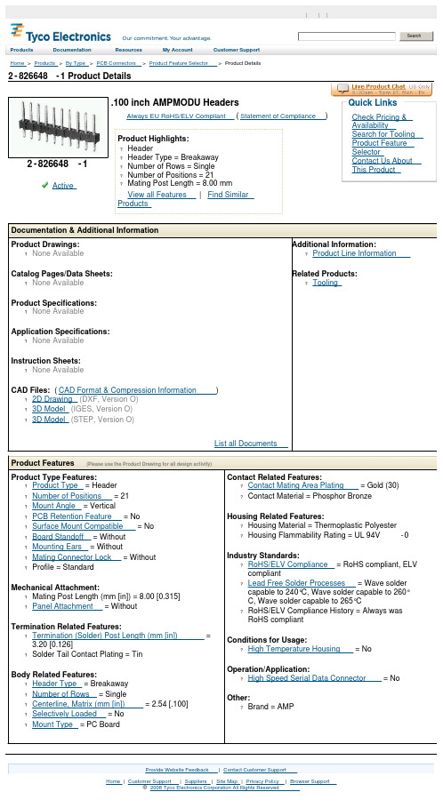
2-826648-1 Product DetailsHome | Customer Support | Suppliers | Site Map | Privacy Policy | Browser Support© 2008 Tyco Electronics Corporation All Rights Reserved SearchProducts Documentation Resources My Account Customer Support Home > Products > By Type > PCB Connectors > Product Feature Selector > Product Details2-826648-1Active .100 inch AMPMODU HeadersAlways EU RoHS/ELV Compliant (Statement of Compliance)Product Highlights:?Header?Header Type = Breakaway?Number of Rows = Single?Number of Positions = 21?Mating Post Length = 8.00 mmView all Features | Find SimilarProductsCheck Pricing &AvailabilitySearch for ToolingProduct FeatureSelectorContact Us AboutThis ProductQuick LinksDocumentation & Additional InformationProduct Drawings:?None AvailableCatalog Pages/Data Sheets:?None AvailableProduct Specifications:?None AvailableApplication Specifications:?None AvailableInstruction Sheets:?None AvailableCAD Files: (CAD Format & Compression Information)?2D Drawing (DXF, Version O)?3D Model (IGES, Version O)?3D Model (STEP, Version O)List all Documents Additional Information:?Product Line InformationRelated Products:?ToolingProduct Features (Please use the Product Drawing for all design activity)Product Type Features:?Product Type = Header?Number of Positions = 21?Mount Angle = Vertical?PCB Retention Feature = No?Surface Mount Compatible = No?Board Standoff = Without?Mounting Ears = Without?Mating Connector Lock = Without?Profile = StandardMechanical Attachment:?Mating Post Length (mm [in]) = 8.00 [0.315]?Panel Attachment = WithoutTermination Related Features:?Termination (Solder) Post Length (mm [in]) =3.20 [0.126]?Solder Tail Contact Plating = TinBody Related Features:?Header Type = Breakaway?Number of Rows = Single?Centerline, Matrix (mm [in]) = 2.54 [.100]?Selectively Loaded = No?Mount Type = PC Board Contact Related Features:?Contact Mating Area Plating = Gold (30)?Contact Material = Phosphor BronzeHousing Related Features:?Housing Material = Thermoplastic Polyester?Housing Flammability Rating = UL 94V-0Industry Standards:?RoHS/ELV Compliance = RoHS compliant, ELVcompliant?Lead Free Solder Processes = Wave soldercapable to 240°C, Wave solder capable to 260°C, Wave solder capable to 265°C?RoHS/ELV Compliance History = Always wasRoHS compliantConditions for Usage:?High Temperature Housing = NoOperation/Application:?High Speed Serial Data Connector = No Other:?Brand = AMPProvide Website Feedback | Contact Customer Support。

MAX488By cl1.概述双路单刀双掷无源开关,全双工,0.25Mbps(无源只是转换,有源除了实现232和485转换外还能保证两者之间的电气隔离)VCC,大于等于4.75V,小于等于5.25V,静态电流120uA1.1.RS485RS-485以差动方式发送和接收,两线间电压差为+(2~6)V表示逻辑1,-(2~6)V表示逻辑0,差动工作是同速率条件下传输距离远的根本原因(可达几十米到上千米);电压比RS232降低了,不易损坏接口电路的芯片,且该电平与TTL电平兼容,方便与TTL电路连接;最高速率10Mbps1.2.RS232RS232-C是EIA(美国电子工业协会Electronic Industry Association)制定的一种串行物理接口标准。
RS是英文“recommended standard(推荐标准)”的缩写,232为标识号,C表示修改次数。
设有25条信号线,包括一个主通道和一个辅助通道。
在多数情况下主要使用主通道,对于一般双工通信,仅需几条信号线就可实现,如一条发送线、一条接收线及一条地线。
RS-232-C标准规定的数据传输速率为每秒50、75、100、150、300、600、1200、2400、4800、9600、19200波特。
RS-232-C标准规定,驱动器允许有2500pF的电容负载,通信距离将受此电容限制;例如,采用150pF/m的通信电缆时,最大通信距离为15m;若每米电缆的电容量减小,通信距离可以增加。
传输距离短的另一原因是RS-232属单端信号传送,存在共地噪声和不能抑制共模干扰等问题,因此一般用于20m以内的通信。
2.封装RO:接收输出(Receiver Output),当A端电压比B端电压高超过200mV,RO输出高当A端电压比B端电压低200mV以上,RO输出低DI:驱动输入,低电平不能低于-0.5V,高电平不能高于VCC+0.5V 输入低电平时Y输出低,Z输出高;输入高电平时Y输出高,Z输出低3.应用。

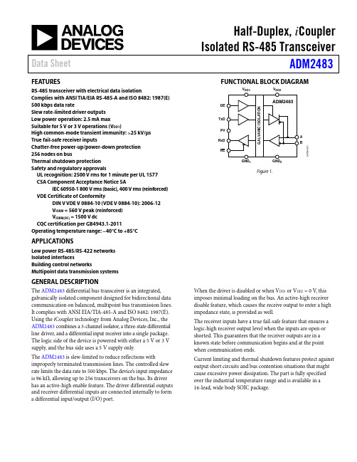
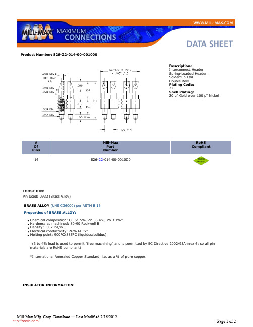

RS485-MODEBUS通讯协议1.字元结构1.1 10―bit字元框(FOR ASCII模式)1位起始位、7位数据位(低位在前,高位在后)、2位停止位(无校验时)1位起始位、7位数据位(低位在前,高位在后)、1位偶校验位、1位停止位(有校验时)1位起始位、7位数据位(低位在前,高位在后)、1位奇校验位、1位停止位(有校验时) 1.2 11―bit字元框(FOR RTU模式)1位起始位、8位数据位(低位在前,高位在后)、2位停止位(无校验时)1位起始位、8位数据位(低位在前,高位在后)、1位偶校验位、1位停止位(有校验时)1位起始位、8位数据位(低位在前,高位在后)、1位奇校验位、1位停止位(有校验时) 波特率:1200,2400,4800,9600,19200,384002.通信资料格式2.3功能码:03H:读出暂存器内容06H:写入一个WORD至暂存器08H:回路侦测2.3.1功能码03H:读出暂存器内容例如:主机(如PC)对地址01H处的从机(如仪表)进行数据读取操作:将从机起始暂存器地址为2000H处的两个连续地址空间中的数据读取出来,表示方法如下RTU模式:ASCII模式:2.3.2功能码06H :写入一个WORD 至暂存器例如:主机(如PC)对地址01H 处的从机(如仪表)进行数据写入操作:主机将数据03E8H 写入到从机暂存器2005H 地址中,表示方法如下RTU 模式:ASCII 模式:2.3.3功能码08H :回路侦测RTU 模式:ASCII 模式:2.4.错误通讯时的额外回应:当控制器(从机如仪表)做通信连接时,如果产生错误,此时控制器(从机如仪表)会回应错误码且将Function code AND 80H回应给主控系统(主机如PC),让主控系统(主机如PC)知道有错误产生。
错误通信时错误码具体涵义请参考“错误码的意义”表格RTU模式:ASCII模式:注:其中将原功能码AND 80H后返回,并在Except code中返回错误码(见下表格)2.5 ASCII模式检查码(LRC Check)将从Address开始到Data Content结束之间的数进行相加,再对相加的和值取其补码就得出检查码。

Q/电器有限公司企业标准布基胶粘带进厂检验要求2010-04-01发布2010-05-15实施公司发布布基胶粘带进厂检验要求Q 1 范围本标准规定了冰箱(柜)用涂胶布基胶粘带的技术要求、检验方法、验收规定。
2规范性引用文件下列文件中的条款通过本标准的引用而成为本标准的条款。
凡是注日期的引用文件,其随后所有的修改单(不包括勘误的内容)或修订版均不适用于本部分,然而,鼓励根据本部分达成协议的各方研究是否可使用这些文件的最新版本。
凡是不注日期的引用文件,其最新版本适用于本部分。
GB/T2828.1 计数抽样检验程序,第1部分:按接收质量限(AQL)检索的逐批检验抽样计划。
GB/T2792 压敏胶粘带180°剥离强度试验方法GB/T4850 压敏胶粘带低速解卷强度的测定GB/T4851 压敏胶粘带持粘性的测定3技术要求3.1 基材:涂塑布粘剂:橡胶3.2规格及公差要求见表13.3外观质量:胶粘带应用均匀卷布,不应有明显变形,缺口和溢胶现象,解卷时无明显胶层不均匀和脱胶现象。
3.4粘接性能见表24 试验方法Q/66-4.1胶带厚度的测试将两张25mm×20mm的试样对粘在一起,用2kg重的压辊滚压2次,用刻度0.01mm的千分尺测定其厚度,再将测定的厚度除以2,其结果应符合表1规定。
4.2宽度、长度的测试宽度、长度的测试用精度1mm的量具测量。
4.3 外观用目测法检查。
4.4 0°持粘力的试验按GB/T4851 规定进行测试。
4.5 常温180°剥离力的试验按GB/T2792 规定进行测试。
4.6低速解卷强度的试验按GB/T4850 规定进行测试。
5 检验规则5.1每批产品应附有生产厂家的检测结果和合格证。
对每批产品进行抽检,按GB/T2828.1特殊检查水平S-2,一次正常抽样查方案AQL=2.5。
FEATURES AND SPECIFICATIONS SPECIFICATIONS MTP* Optical
Round Ribbon Cable Assemblies 86282
Molex's MTP round jacketed ribbon cable assemblies provide easier installation than traditional flat ribbon cables in optical networks. System designers and installers have found it difficult to route flat ribbon cable in complex networks. The use of round ribbon cables allows the installer greater flexibility when routing multiple jacketed cables in dense system networks.
Molex developed a patent pending transition sleeve which maintains the routing features of the round cable while allowing the cable to be secured to the MTP connector. The primary benefit of the round ribbon cable is realized with the use of multiple ribbons within a single jacket. Stacked ribbons in traditional flat jacketed ribbon cables are prone to piston in relation to each other, causing attenuation in longer cable assemblies. The round ribbon cable prevents the “pistoning” effect by encasing the ribbons in a solid buffer core, preventing them from moving. Fiber counts up to 24 fibers are currently available while development continues on the 48 and 72 fiber versions.
Reference Information Packaging: Custom per assembly Mates With: MPO and MTP Connectors (86081 & 86082 Series)
Optical
Fiber Specifications:
Core: 50µm†
Clad: 125µm
Coating: 250µm
Insertion Loss (IL):
12F: 0.15 dB Typ. <0.5dB max.
24F: 0.25 dB Typ. <0.75dB max.
72F: 0.35 dB Typ. <1.00dB max. Attenuation:
850nm: Typ 2.5 dB/km
Max 3.0 dB/km
Min. Overfilled Bandwidth:
850nm: 500 MHz/km
1300nm: 500 MHz/km Mechanical
Min. Bend Radius: 3 inches for 12 fibers
(10X the outer jacket diameter)
Max. Tensile Rating: 667.23N (150 lbf) Physical
Outer Jacket: PVC
Fire Rating: OFNR (Riser) and OFNP (Plenum) Operating Temp.: -20 to +70°C
Storage Temp.: -40 to +70°C
Install Temp.: -0 to +70°C
Dimensions:
12F (2 Ribbons x 6 Fibers): 3.3mm OD
16F (2 Ribbons x 8 Fibers): 4mm OD
24F (2 Ribbons x 12 Fibers): 5mm OD
48F (4 Ribbons x 12 Fibers): N/A‡
72F (6 Ribbons x 12 Fibers): N/A‡
*MTP is a registered trademark of US Conec Ltd.
†Singlemode (9/125µm) and Multi-mode (62.5/125µm) may be available with Minimum Order Quantity
‡
Under development
Features and Benefits
I Round outer jacket is easily installed by end user I Flexible PVC outer jacket is able to bend easily I Plenum-rated meets system flammability requirements I Ribbons encased in solid buffer core ensures
reduced fiber pistoning between ribbons
I Multiple ribbons stacked inside round jacket provide
a low-profile solution for high-density applications
Optical Round Ribbon Cable Assemblies Offer Greater Flexibility in Interconnecting
Optical Network Systems
MTP Round Ribbon Cable Assembly with Long
Transition Sleeve
Proto-type Round Ribbon 72 Fiber Cable Assembly
MTP to MTP Round Ribbon Cable Assembly
APPLICATIONS
MTP* Optical Round Ribbon Cable Assemblies 86282
I Parallel optic transceiver interconnection I High Density interconnects for:- Optical electrical modules - PC cards and patch panels - Optical switches and routers - Data communication centers
Americas Headquarters Lisle, Illinois 60532 U.S.A.1-800-78MOLEX amerinfo@ Far East North Headquarters Yamato, Kanagawa, Japan 81-462-65-2324feninfo@ Far East South Headquarters Jurong, Singapore 65-6-268-6868fesinfo@ European Headquarters Munich, Germany 49-89-413092-0eurinfo@
Corporate Headquarters 2222 Wellington Ct.Lisle, IL 60532 U.S.A.630-969-4550Fax:630-969-1352
Visit our Web site at /fiber/mtp_roundcable.html
Order No. USA-272 Rev. 1
Printed in USA/JI/2004.11
©2004, Molex
ORDERING INFORMATION
Cable Assemblies: Transition Sleeve Boot Options
Cable Assemblies: No Transition Sleeve Boot Options
Notes:
- Only sold as terminated jumpers or pigtails
- The cable construction will be customer and system specific
- All new opportunities should be reviewed with the Molex Fiber Optics program or product manager。