SINUMERIK 808D_编程和操作手册_车削_第一部分_201212
- 格式:pdf
- 大小:11.48 MB
- 文档页数:96

SINUMERIK SINUMERIK 808D调试手册开机调试手册适用于以下控制系统:SINUMERIK 808D 车削(软件版本: V4.4 SINUMERIK 808D 铣削(软件版本:V4.4 目标使用人群:电气工程师、校准工程师以及测试工程师03/20126FC5397-4EP10-0RA0法律资讯警告提示系统为了您的人身安全以及避免财产损失,必须注意本手册中的提示。
人身安全的提示用一个警告三角表示,仅与财产损失有关的提示不带警告三角。
警告提示根据危险等级由高到低如下表示。
危险表示如果不采取相应的小心措施, 将会导致死亡或者严重的人身伤害。
警告表示如果不采取相应的小心措施, 可能导致死亡或者严重的人身伤害。
小心带有警告三角,表示如果不采取相应的小心措施,可能导致轻微的人身伤害。
小心不带警告三角,表示如果不采取相应的小心措施,可能导致财产损失。
注意表示如果不注意相应的提示,可能会出现不希望的结果或状态。
当出现多个危险等级的情况下,每次总是使用最高等级的警告提示。
如果在某个警告提示中带有警告可能导致人身伤害的警告三角,则可能在该警告提示中另外还附带有可能导致财产损失的警告。
合格的专业人员本文件所属的产品 /系统只允许由符合各项工作要求的合格人员进行操作。
其操作必须遵照各自附带的文件说明,特别是其中的安全及警告提示。
由于具备相关培训及经验,合格人员可以察觉本产品 /系统的风险,并避免可能的危险。
Siemens 产品请注意下列说明:警告Siemens 产品只允许用于目录和相关技术文件中规定的使用情况。
如果要使用其他公司的产品和组件,必须得到 Siemens 推荐和允许。
正确的运输、储存、组装、装配、安装、调试、操作和维护是产品安全、正常运行的前提。
必须保证允许的环境条件。
必须注意相关文件中的提示。
商标所有带有标记符号 ® 的都是西门子股份有限公司的注册商标。
标签中的其他符号可能是一些其他商标,这是出于保护所有者权利的目地由第三方使用而特别标示的。
Sinumerik 808D Programming and Operating Procedures for Turnings NotesProgramming and Operating — Turning Page 2 808D808DPage 3 Programming and Operating — TurningsBasic knowledge of programming for turning is required, before operating of a machine !NotessProgramming and Operating — Turning Page 4 808D808DPage 5 Programming and Operating — TurningMCP mode ChangingMode NavigationThe 808D machine control panel (MCP) is used to select the machine operating Menu navigationOperating area navigationAxis movement The 808D machine controlpanel (MCP) is used tocontrol manual operation ofthe axis.The machine can be movedwith the appropriate keys.OEM key The 808D machine controlpanel (MCP) is used to con-trol OEM machine functions.The machine functions canbe activated with the appro-808D(PPU)haseight vertical softkeys(abbr. SKs) on theright of the screen.These SKs can beactivated with thecorresponding button(located on the right). 808D(PPU)has eight horizontal SKs on the bottom of thescreen. These SKs can be activated with the corresponding button (located below).Programming and Operating — Turning Page 6 808D808D The service mode is opened with the appropriate key combination.In the service mode, the password can be activated and deactivated.The machine zero point (M) is determined by the machine manufacturer and cannot be changed.The workpiece zero point (W) is the origin of the workpiece coordinate system.The reference point (R) is used for synchronizing the measuring system.The tool holder reference point (F) is used to determine the tool offset.s NotesProgramming and Operating — Turning Page 8 808DStep 1Turn on the main switch of the machine.Step 2Make sure you perform the following operationRelease all the EMERGENCY STOPbuttons on the machine!End808D Page 9 Programming and Operating — TurningStep 3Step 2EndProgramming and Operating — Turning Page 10 808Ds Notes808D Page 11 Programming and Operating — Turnings NotesProgramming and Operating — Turning Page 12 808DPlease make sure the system is in JOG mode.Press “Offset” on the PPU.808D Page 13 Programming and Operating — TurningPress the “New tool” SK on the PPU.Press the “OK” SK on the PPU Press the “Input” button on the PPUThe correct “Edgeposition” selectiondirectly determinesthe correct toolcompensation which willbe described in thenext unit.Observe the relationship between the tool point direction and the positivedirection of the X axis and the Z axis.Find the corresponding position relationship in the figure belowNote that the tool tip direction here is the direction afterthe correct tool offset, not only the direction in tool load-The tool edge position code can also be changed in the posi-tion showed in the figure.Enter “3” at “Edgeposition”.Select the type of required tool.Note: Not every tool has eight position codes. All the options are shown above.Programming and Operating — Turning Page 14 808D808DPage 15 Programming and Operating — TurningPress the “Offset” key on the PPU.Press the “Edges” SK on the PPU. Use “D” code to represent the tool edge. The system activates theNo.1 tool edge as default at the beginning.orPress the “New edge” SK on the PPU.Press the “Tool list” SK on the PPU. → →→ →Programming and Operating — TurningPage 16808DPress the “Machine” key on the PPU.Press the “T.S.M” SK on the PPU. Press “CYCLE START” on the MCP.Press the “Back” SK on the PPU.Press the “JOG” key on the MCP.A maximum of nine tool edges can be created for each tool!Different tool lengths and radii can be saved in different tool edges as required.Please select the right tool edge for machining according to requirement!A handwheel can control the axis motion instead of the “JOG” button.Press the “Machine” key on the PPU.Press the “Handwheel” key on the MCP.The selected axis can now be moved with the handwheel.if set MD14512[16]=80 , the system will deactivate the func-Under “WCS” or “MCS”,a handwheel will be shownbeside the axis symbols,representing that the axiscan be moved using hand-808D Page 17 Programming and Operating — TurningStart the spindle before adjusting tools as follows: Press the “Machine” key on the PPU.Press the “CYCLE START” key on the MCP.Press the “Back” SK on the PPU.Press “Reset” on the MCP to stop the spin-dle rotation.Measure length:XPress the “Machine” key on the PPU.Press the “JOG” key on the MCP.Programming and Operating — Turning Page 18 808DUse the“Handwheel”key on theMCP andselect a suita-ble feedrateMove directly to zero point.Press the “Set length X” SK on the PPU.“X=0” or “Z=0” in the workpiececoordinate system is shown as “X0” /“Z0” in the following text.808D Page 19 Programming and Operating — TurningMove directly to zero point Press the “Back” SK on the PPU.Press the “Set length Z” SK on the PPU.Use the“Handwheel”key on theMCP andselect a suita-ble feedrateoverride toProgramming and Operating — Turning Page 20 808DPress the “Machine” key on the PPU. Press the “JOG” key on the MCP. Press the “Machine” key on the PPU. Press the “T.S.M” SK on the PPU.Press “CYCLE START” on the MCP. Press the “Reset” key on the MCP to stop the coolant function.You can see that the coolant function key on the MCP is active.In order to ensure the machine safety and correctness, the results of the tool offset should be tested appropriately.Press the “Machine” key on the PPU.Press the “MDA” key on the MCP.The ROV function activates the feedrate override switch underPress “CYCLE START” on the MCP.Increase the feedrate override gradually to avoid accidents caused by an axis moving too fast and observe whether the axis moves to the set position.NotesNotesBefore measuring, the spindle can be started as follows: Press the “Machine” key on the PPU.Press the “JOG” key on the MCP.Press “CYCLE START” on the MCP.Make sure the active tool is the measured toolPress the “Machine” key on the PPU.Press the “JOG” key on the MCP.Press the “Reset” key on the MCPto stop the spindle rotation.Press the “Offset” key on the PPU.Press the “Back” SK on the PPU.Enter tool number “1” in“T”.Set “Save in” as “G54” (or other offset).Set “Distance” as “0”Press the “Set work offset” SK on the PPU.Repeat the operations to set the “X” zero point. Press the “Back” SK on the PPU after measuring.In order to ensure the machine safety and correctness, the results of the tool offset should be tested appropriately.Press the “MDA” key on the MCP.The ROV function activates the feedrate override switch underPress “CYCLE START” on the MCP.Increase the feedrate override gradually to avoid accidents caused by an axis moving too fast and observe whether the axis moves to the set posi-tion.NotesNotes808D Page 31 Programming and Operating — TurningSelect NC as the storage location for the program. Programs can only be created12After editing the system will save it automatically.Programming and Operating — Turning Page 32 808D808D Page 33 Programming and Operating — TurningX0 Z50G500 ZG500 XX0 Z50G54 ZG54 XG54 X0G54 Z0G500 ZG500 XProgramming and Operating — Turning Page 34 808DStraight line (parallel/unparallel to axis)Straight line (parallel/unparallel to axis)808D Page 35 Programming and Operating — TurningG41 → direction along the tool mo-G42 → direction along the tool mo-Programming and Operating — Turning Page 36 808D808D Page 37 Programming and Operating — TurningProgramming and Operating — Turning Page 38 808DNotes808D Page 39 Programming and Operating — TurningNotesProgramming and Operating — Turning Page 40 808DThe easiest way to “Turn.” SK, you can enter the cycle and The “Contour turn-ed parameters canfollows:With the “New” SK and “Contour milling”, the operation can beN170 CYCLE95( "DEMO:DEMO_E", 2.5, 0.2 , 0.1 , 0.15 , 0.35 , 0.2 , 0.15 , 9 , , ,)Don't change!;*GP*;*RO*;*HD*The relevant cycle Select “Groove”N230 CYCLE93( 30.00000, -30.50000, 7.00000, 5.00000, 0.00000, 0.00000, 0.00000, 1.00000, 1.00000, ,0.00000, 0.20000, 0.10000, 2.50000, 0.50000, 11, )The easiest way toThe relevant cycle Select “Thread”N290 CYCLE99( 0, 20.00000, -18.00000, 20.00000, 2.00000, 0.00000, 1.00000, 0.01000, 29.00000, 0.00000, 1, 2, 2.50000 , 3001031, 1, , 0, 0, 0, 0, 0, 0, 0, 1, , , , 0)N375 CYCLE82( 5.00000, 0.00000, 2.00000, -5.00000, 0.00000, 0.50000)。

螺纹车削循环—CYCLE99======================系统:SINUMERIK 808D TSINUMERIK 808DA T=======================================================CYCLE99 基本上集合所有的螺纹工艺,包括公制螺纹、英制螺纹、单头螺纹、多头螺纹,直螺纹,锥螺纹,螺纹链等,使用CYCLE99车削螺纹无需计算X轴的每次的切削深度,只需设置螺纹深度及需要切削的次数,使用非常的灵活方便。
例:车削如下图的工件(单位:mm)毛坯: 铝棒Ø65*100工件装夹:工件端面到卡盘端面的距离大于75刀具及切削用量:刀具名称刀号/补偿号转速 进给X轴单边切深换刀点 说明粗 精 粗精2.0螺纹刀T1D1 600600 2 2 / X100Z150粗精车螺纹对刀方法请参见编程操作手册注:加工螺纹之前的外圆车削,在之前的CYCLE95中已经介绍,本文只介绍CYCLE99螺纹车削。
程序编辑:<1>创建程序1.点击“程序管理”2.点击屏幕左下角软按键“NC”3.点击屏幕右上角软按键“新建”,输入程序名“SSSS”4.点击屏幕右下角软按键“确认”,系统切换到(图一)编辑程序界面图一<2>编辑程序1.输入程序(图二):图二2.点击屏幕中下方软按键“车削”3.点击屏幕右上角软按键“螺纹”4.在点击“直螺纹”,系统显示如下螺纹参数设置界面,按照图三输入需设置的螺纹参数图三4.参数设置完成后,点击“确认”,回到程序界面,接着输入程序。
图四5.程序输完后,点击屏幕左下角软按键“编辑”,回到编辑模式。
6.在点击屏幕右上角“执行”,机床自动跳到“自动”模式,即可开始加工。
在刀具、补偿都设置好及正确装夹毛坯的前提下,按MCP(操作面板)右下角的“循环启动”按键,开始加工。
说明:<1> 以上讲解,是零件螺纹车削编程的操作步骤,和其它系统不同的地方在于CYCLE99螺纹参数的编写方式,一开始使用可能感觉有点混乱,但是,编写几次就熟悉了。

Training manualSinumerik 808D ADVANCED Commissioning Guide Version 2013-09s NotesCommissioning Guide Page 2 808D ADVANCED Turning and Milling808D ADVANCED Turning and MillingPage 3 Commissioning GuidesThe warranty is connected to the product serial number of the808D ADVANCED.You can find the product serial number:On the back of PPU system hardware.Picture 1product serialnumberOr on the display.After switch-on, press the “Shift” and “Alarm” keys together.Then press the “Extension” buttonThis will enter into the system area.(see picture 1)Press softkey to enter the screen of service axes ( see picture 2).Press softkey to enter the screen of version data ( see picture 3).You can find the serial number information which needs to be registeredstarting with the letters “SZV”.For any question about ”SZV” serial number and the steps to register ,Please contact the Siemens Technical Support & Service Hotline:+86 4008104288Picture 2Picture 3Product identification / SINUMERIK 808D ADVANCEDNotesCommissioning Guide Page 4 808D ADVANCED Turning and Milling808D ADVANCED Turning and Milling Page 5 Commissioning GuideNotesCommissioning Guide Page 6 808D ADVANCED Turning and Milling808D ADVANCED Turning and Milling Page 7 Commissioning GuideCommissioning Guide Page 8 808D ADVANCED Turning and MillingIn the following technical drawing the mounting dimensions for the PPU and the MCP are shown.You must provide sufficient space (recommended distance: 80 mm) between the maintenance door and the cabinet wall for replacing the For further components refer to :- Commissioning manual page 21Spindle encoderUSB stickHandwheels+24V DC power supply808D MCPMotor Motor MotorSINUMERIK808D ADVANCED PPUPC/PG Spindle motorInverter or servo spindle driveNotes :1. PC and memory stick is not included in scope of delivery.2. "USB", "Handwheel","24V DC power supply", "Emergency stop button", "Inverter or servo spindle drive", "Spindle encoder" are also not included in scope of delivery.Emergency stop buttonFactory NetworkSINAMICS V70 In total 14 clamps are provided together with the delivery of PPU 1. 8 clamps for mounting PPU. 2. 6 clamps for mounting MCP.Terminator808D ADVANCED Turning and Milling Page 9 Commissioning GuideBBAAX10 NCMCPThe clamps are located at the positions indicated with the black triangles. The black triangles can be seen in the above picture highlighted with red circles.PPU = P anel P rocessing U nit MCP = M achine C ontrol P anel808D PPU808D MCPCommissioning Guide Page 10 808D ADVANCED Turning and MillingThe clamps are located at the positions indicated with the black triangles. The black triangles can be seen in the following picture with red circles.MCPMCPVertical MCP without handwheelVertical MCP with ingrate handwheel808D PPU808D MCPThe cut-out dimensions for the 808D ADVANCED vertical PPU and Cut-out dimensionsElectrical cabinet> 20 mm> 20 mm> 20 mm> 20 mm> 100 m m> 100 m mSINAMICS V70 Servo driveSINAMICS V70 Servo driveSINAMICS V70 Servo drive For further information refer to :-Circuit breaker (optional) Switches off the power supply to protect thenetwork when overcurrent occursLine filter (optional)Protects the network from harmonic load and/or interference voltages.Braking resistor (optional) Absorb excess regenerative energy in the DC link when the capacity of the internal braking resistor is insufficientSINUMERIK 808D ADVANCEDEmergency stop button (optional)Stops a motor in emergency cases.24 V DC power supplyBrake cableEncoder cableP o w e r c a b l e3 phase 380V AC line supplyL1 l2 l3SIMOTICS S-1FL6 servomotorSINIMICS V70 servodriveAccessories not included in the scope of deliveryConnections not necessarily requiredShielding layerDrive bus terminator14 311 13414 126 47Legend Interface CommentMCP Back X10USB interface, for connection with thePPUBB AAX10 NCMCP back1NoteConnect USB cable between X30 on PPU and X10 on MCP.These 4 aspects should be considered during selection of 24V DC supply calculation base on name plate. Consideration of redundancy coefficient base on regulation of OEMMCP backX10 NCE-stop Limit X+ Limit X - Limit Y+ Limit Y- Limit Z+ Limit Z- Ref X M1 2 3 45 6 7 8 9 10X100+ 24VMillingDigital inputsDistribution I/O board For the connection of distribution I/O on X301must be configured. MLFB for distribution I/ORef Y Ref ZMagazine countMagazine at spindle position Magazine at original position Magazine at release position Magazine at clamp position M1 2 3 4 5 6 7 8 9 10X101+24VDisk magazine: magazine rotating CW Disk magazine: magazine rotating CCW Disk magazine: magazine in spindle position Disk magazine: magazine in original position Disk magazine: spindle tool releaseHandheld unit active M1 2 3 4 5 6 7 8 910X201Coolant level lowCooling motor overload Lubrication level lowLubrication motor overload M1 2 3 4 5 6 7 8 9 10X102+24VWorking lampChip remover forward Chip remover reverse Cooling pump Lubrication pump Safety door open M1 2 3 4 5 6 7 8 910X200Turning Digital inputs11 - Handheld unit: axis X selected 13 - Handheld unit: axis Z selected 14 - Handheld unit: axis 4th selected 15 - Handheld unit: INC X1 16 - Handheld unit: INC X10 17 - Handheld unit: INC X100 18 - Handheld unit: enabledMFor the connection of distribution I/O on X301must be configured. MLFB for distribution I/O X301 Distributed I/OE-stop Limit X+ Limit X -Limit Z+ Limit Z- Ref X M1 2 3 4 56 7 8 9 10X100+ 24VTurret motor overload Reserved for other turretChuck openCoolant level lowCooling motor overload Lubrication level lowLubricating motor overload M1 2 3 4 5 6 7 8 9 10X102+24VWork lampTailstock advancing Tailstock retracting Coolant pump Lubrication pump Chuck output 1 Chuck output 2 M1 2 3 4 5 6 7 8 910X200+24VTurret motor CW Turret motor CCWReserved for other turret Reserved for other turret Gear change: low Gear change: highHandheld unit active M1 2 3 4 5 6 7 8 910X201Ref. Z T1 T2 T3 T4 T5 T6 M 12345678910X101Spindle/ inverter motor(black)blackblack blackSpindle/ inverter motorSINUMERIK 808D ADVANCED PPUSINUMERIK 808D ADVANCED PPUIn some cases, an extra language has to be selected. Double-click the “Setup.exe”During the installation various dialogue boxes will appear. The dialogue boxes should be acknowledged and where necessary installation data should be entered and confirmed.Installing all the software packages will take approximately 30 minutes. When the installation has finished icons will be placed on the desk top.Activate the PLC connection setting in 808D (password set to “sunrise”) Double click highlighted area.The connection is now established, this is shown by a green box.Status description on front LED’s of PPUIf the drive data is different from the 808D backup data, a data synchroni-zation is required for synchronizing the drive data files between the NCStatus description on SINAMICS V70 Item DescriptionStatus LED’s indicator colour RDY-GreenStatus on power up with incremental encoderStatus on power up with absolute encoderType in “SUNRISE”Type in time and date using the key-board and the andWhen the PPU shows the followingTo accept the selection.On power up of the control the current alarms 4060 and 400006 can be acknowledged with the “Reset” and “Alarm cancel” buttons Type in SUNRISESelect the language withYou can load a new system language or update an existing language on Siemens will provide each language in the form of an archive file.“Option”, a new licence key Press the SKTo active an “Option”, enter Press the SKFunctionvertical =0 - horizontal=1Spindle braking timeMax Tool number in magazineLubrication intervalLubrication durationTool magazine:spindle poisoning angleTool magazine: Preparation position of Z axes for tool changeTool magazine: Tool changing posion of Z axesTool magazine: velocity of Z axis, Go to tool change preparation positionTool magazinevelocity of Z axis, back to tool change preparation positionRange Functionality- flat bed=0 - inclined bed = 15~200 Spindle braking time4, 6 Max Tool number in turret.(for tool amount >6, PLC to beprogrammed by customer them-selves)5~30 HED turret: Tool clamping time for 30~200 HED turret: Time monitoring fortool change5~300 Lubrication interval12~2000 Lubrication durationPLC MD is to be adapted to suit the machine To continue press the SKChanges will be activated MD set to default value MD set to previous valueIt may be that the machine tool builder requires further PLC functionality, if this is required the PLC has to be modified.To install PLC programming tool, follow the information in :- PLC Subroutines manual page 8 (install PLC programming tool) To make a connection to the PPU, press SK Then follow the information in:-PLC Subroutines manual page 18To continue press the SKFirst the “Sample PLC blocks” should be uploaded to the PC, then the modifications can be made to achieve the required functionality. Once this has been completed, the PLC should be put into stop and the modified PLC should be downloaded into the PPU. The PLC must then bePLC Subroutines manual page 25To continue press the SK All I/O status must be checked with the electrical drawing using the following SK’s. The status is shown on the right hand side as shown Vertical SK’s allow you to select digital inputs or outputs and selection ofTo continue press the SKChoose digital inputChoose digital outputChoose the digital O/I addresses of Byte -Choose the digital O/I addresses of Byte +You can edit the PLC user alarm text either directly on the HMI, or off line by transferring the file using a USB stick.Vertical SK’s allow you to import and export the text file from the HMI, and SK that that allows the text file to be directly edited on the HMI.To continue press the SKImport the backup alarm text into the PPU Edit the alarm textExport the finished alarm text from the PPU Set “address data” for each axis: Remove drive bus cable from terminal X10 Press M repeatedly (until “FUnC” is displayed) Press ▼(until “Addr” is displayed) Press ▼(until desired address is displayed) Press ▼(until “SAvE” is displayed) Screen will go blank (wait about 20sec) (Screen will display “S OFF” or a fault code) Replace drive bus cable to terminal X10 Drives must now be powered off/onStarts the configuring of the V70 drive.Starts the configuration of spindle motor motors on the M3 Drive BusSelect the motor from the table that matches the motor name plate.Starts the configuring of the motor data to the drive All axis motors are indentifiedStarts the configuration of each unidentified spindleAll axis and spindle motors are indentified.You can edit the spindle machine data for the required axis.Vertical SK’s allow you to edit, activate or set as default value.MD set to default valueMD set to previous valueTo continue press the SK To continue press the SKFollowed by creating the drive dataYou can edit the axis machine data and the for the required axis. Vertical SK’s allow you to edit, activate or set as defaultUsed to select the axis (X or Z turn or X, Y, or Z mill)Changes will be activatedMD set to default valueMD set to previous valueAn axis can be referenced You can edit the spindle machine data required.Vertical SK’s allow you to edit, activate or set as defaultUsed to select the axis (X or Z turn or X, Y, or Z mill)Changes will be activatedMD set to default valueMD set to previous valueTest spindle in MDA modeVertical SK allows you to, create the “series start-up archive” press SK Create production archiveWhen creating the productionbackup, store archive to USB You can edit the axis machine data for the required axis.Vertical SK’s allow you to edit, activate or set as defaultUsed to select the axis (X or Z turn or X, Y, or Z mill)Changes will be activatedMD set to default valueMD set to previous valueYou can edit the axis machine data for the required axis.Vertical SK’s allow you to edit, activate or set as defaultUsed to select the axis (X or Z turn or X, Y, or Z mill)Changes will be activatedMD set to default valueMD set to previous value You can edit the axis machine data for the required axis.Vertical SK’s allow you to edit, activate or set as defaultUsed to select the axis (X or Z turn or X, Y, or Z mill)Used to enter compensation data via the HMIChanges will be activatedThere are three “Optimization2 Aggressive measurement3 Conservative measurementPress “Start Optim.” SK Select the required strategy.To continue press the SKThe following window will be shown.To continue press the BUTTON To continue press the BUTTONThe axis optimization operation process will now optimise MZ1 axis of highPress “Next” SK to continueand low frequency measurement process. (a repeat of the 8 passes asVertical SK allows you to, create the “production archive” press SK “Create Create Start-up archivearchive, store archive to USB。
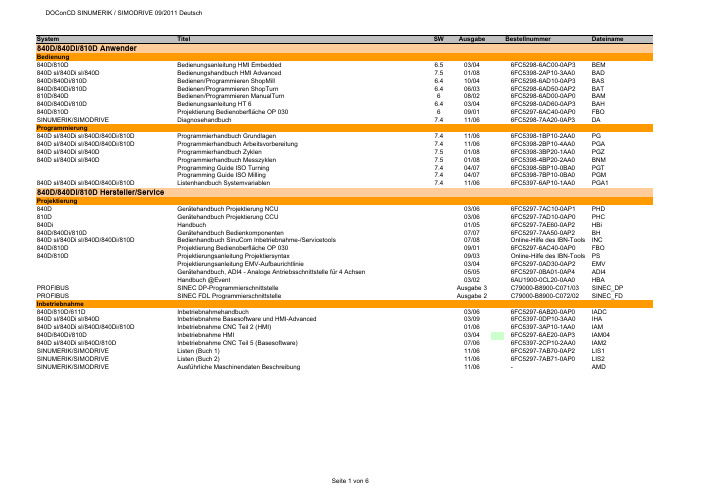
System Titel SW Ausgabe Bestellnummer Dateiname 840D/840Di/810D AnwenderBedienung840D/810D Bedienungsanleitung HMI Embedded 6.503/046FC5298-6AC00-0AP3BEM840D sl/840Di sl/840D Bedienungshandbuch HMI Advanced 7.501/086FC5398-2AP10-3AA0BAD840D/840Di/810D Bedienen/Programmieren ShopMill 6.410/046FC5298-6AD10-0AP3BAS840D/840Di/810D Bedienen/Programmieren ShopTurn 6.406/036FC5298-6AD50-0AP2BAT810D/840D Bedienen/Programmieren ManualTurn608/026FC5298-6AD00-0AP0BAM840D/840Di/810D Bedienungsanleitung HT 6 6.403/046FC5298-0AD60-0AP3BAH840D/810D Projektierung Bedienoberfläche OP 030609/016FC5297-6AC40-0AP0FBO SINUMERIK/SIMODRIVE Diagnosehandbuch7.411/066FC5298-7AA20-0AP3DA Programmierung840D sl/840Di sl/840D/840Di/810D Programmierhandbuch Grundlagen 7.411/066FC5398-1BP10-2AA0PG840D sl/840Di sl/840D/840Di/810D Programmierhandbuch Arbeitsvorbereitung 7.411/066FC5398-2BP10-4AA0PGA840D sl/840Di sl/840D Programmierhandbuch Zyklen 7.501/086FC5398-3BP20-1AA0PGZ840D sl/840Di sl/840D Programmierhandbuch Messzyklen7.501/086FC5398-4BP20-2AA0BNMProgramming Guide ISO Turning7.404/076FC5398-5BP10-0BA0PGTProgramming Guide ISO Milling7.404/076FC5398-7BP10-0BA0PGM840D sl/840Di sl/840D/840Di/810D Listenhandbuch Systemvariablen 7.411/066FC5397-6AP10-1AA0PGA1 840D/840Di/810D Hersteller/ServiceProjektierung840D Gerätehandbuch Projektierung NCU 03/066FC5297-7AC10-0AP1PHD810D Gerätehandbuch Projektierung CCU03/066FC5297-7AD10-0AP0PHC840Di Handbuch01/056FC5297-7AE60-0AP2HBi840D/840Di/810D Gerätehandbuch Bedienkomponenten07/076FC5297-7AA50-0AP2BH840D sl/840Di sl/840D/840Di/810D Bedienhandbuch SinuCom Inbetriebnahme-/Servicetools07/08Online-Hilfe des IBN-Tools INC840D/810D Projektierung Bedienoberfläche OP 03009/016FC5297-6AC40-0AP0FBO840D/810D Projektierungsanleitung Projektiersyntax09/03Online-Hilfe des IBN-Tools PSProjektierungsanleitung EMV-Aufbaurichtlinie03/046FC5297-0AD30-0AP2EMVGerätehandbuch, ADI4 - Analoge Antriebsschnittstelle für 4 Achsen05/056FC5297-0BA01-0AP4ADI4Handbuch @Event03/026AU1900-0CL20-0AA0HBA PROFIBUS SINEC DP-Programmierschnittstelle Ausgabe 3C79000-B8900-C071/03SINEC_DP PROFIBUS SINEC FDL Programmierschnittstelle Ausgabe 2C79000-B8900-C072/02SINEC_FD Inbetriebnahme840D/810D/611D Inbetriebnahmehandbuch03/066FC5297-6AB20-0AP0IADC840D sl/840Di sl/840D Inbetriebnahme Basesoftware und HMI-Advanced03/096FC5397-0DP10-3AA0IHA840D sl/840Di sl/840D/840Di/810D Inbetriebnahme CNC Teil 2 (HMI)01/066FC5397-3AP10-1AA0IAM840D/840Di/810D Inbetriebnahme HMI03/046FC5297-6AE20-0AP3IAM04840D sl/840Di sl/840D/810D Inbetriebnahme CNC Teil 5 (Basesoftware)07/066FC5397-2CP10-2AA0IAM2 SINUMERIK/SIMODRIVE Listen (Buch 1)11/066FC5297-7AB70-0AP2LIS1 SINUMERIK/SIMODRIVE Listen (Buch 2)11/066FC5297-7AB71-0AP0LIS2 SINUMERIK/SIMODRIVE Ausführliche Maschinendaten Beschreibung11/06-AMDFunktionen840D sl/840Di sl/840D/840Di/810D Funktionshandbuch Grundfunktionen11/066FC5397-0BP10-2AA0FB1840D sl/840Di sl/840D/840Di/810D Funktionshandbuch Erweiterungsfunktionen11/066FC5397-1BP10-2AA0FB2840D sl/840Di sl/840D/840Di/810D Funktionshandbuch Sonderfunktionen11/066FC5397-2BP10-2AA0FB3611D/840D/810D Funktionshandbuch Antriebsfunktionen05/106SN1197-0AA80-2AP1FBA840D/840Di/810D Funktionsbeschreibung Werkzeugverwaltung09/056FC5297-6AC60-0AP1FBW802D sl/840D/840D sl/840Di/840Di sl/810D Funktionshandbuch ISO-Dialekte für SINUMERIK03/076FC5297-7BP10-0AA0FBFA840D/611D Funktionshanduch HLA-Modul 03/066SN1197-0AB60-0AP4FBHLA840D/611D Funktionsbeschreibung ANA-MODUL02/006SN1197-0AB80-0AP0FBAN840D/611D Funktionsbeschreibung Safety Integrated03/066FC5297-7AB80-0AP1FBSI840D sl/840Di sl/840D/840Di/810D Funktionsbeschreibung Synchronaktionen11/066FC5397-5BP10-2AA0FBSY840D Funktionsbeschreibung Digitalisieren 07/996FC5297-4AC50-0AP0FBD840D/840Di/810D Funktionsbeschreibung Ferndiagnose03/046FC5297-0AF00-0AP3FBFE840D Funktionsbeschreibung C-PLC-Programmierung03/966FC5297-3AB60-0AP0FBP840D/840Di/810D Funktionsbeschreibung ShopMill 02/056FC5297-6AD80-0AP3FBSP840D/840Di/810D Funktionsbeschreibung ShopTurn03/046FC5297-6AD70-0AP2FBT840D/810D Funktionsbeschreibung ManualTurn08/026FC5297-6AD50-0AP0FBMA840D/810D Funktionsbeschreibung ManualTurn, Ergänzende Informationen07/04-FBMAx802D/802D base lineAnwender802D base line Bedienen und Programmieren, Drehen208/056FC5698-2AA00-1AP4802D_BPD802D Kurzanleitung Drehen111/006FC5698-1AA30-0AP0802DBNKD802D Kurzanleitung ISO-Dialekt Drehen109/016FC5698-1AA60-0AP0802D_ISD802D Bedienen und Programmieren, Fräsen208/056FC5698-2AA10-1AP5802D_BPF802D Kurzanleitung Fräsen111/006FC5298-1AA40-0AP0802DBNKF802D Kurzanleitung ISO-Dialekt Fräsen 109/016FC5698-1AA50-0AP0802D_ISF802D Diagnoseanleitung110/026FC5698-2AA20-0AP1802D_DIA Hersteller/Service802D base line Funktionsbeschreibung11/036FC5697-2AA10-0AP2802D_fb802D base line Inbetriebnahmehandbuch08/056FC5697-2AA00-1AP5802D_IBNGerätehandbuch, ADI4 - Analoge Antriebsschnittstelle für 4 Achsen05/056FC5297-0BA01-0AP4ADI4802S/802C base lineAnwender802S/ 802C base line Bedienen und Programmieren, Drehen408/036FC5598-4AA01-0AP0802SC_BPD 802S/ 802C base line Bedienen und Programmieren, Fräsen408/036FC5598-4AA11-0AP0802SC_BPF802S/ 802C base line Diagnoseanleitung408/036FC5598-4AA21-0AP0802SC_DIA Hersteller/Service802S/802C base line Funktionsbeschreibung08/036FC5597-4AA11-0AP0802SC_FB802C base line Inbetriebnahmeanleitung08/036FC5597-4AA21-0AP0802C_IBN802S base line Inbetriebnahmeanleitung08/036FC5597-4AA01-0AP0802S_IBN SIMODRIVE base line A Start-Up09/046SN1197-0AB21-0BP1802C_IBN_SBLASIMODRIVE611 digital Projektierungshandbuch Umrichter05/086SN1197-0AA00-1AP1PJU611 universal Funktionshandbuch06/116SN1197-0AB20-2AP3FBU611 universal Tausch Ersatzteil07/05A5E00150834FBU_TE611 universal Tausch Ersatzteil HR/HRS12/05A5E00423710FBU_TEH611 analog Inbetriebnahmeanleitung10/006SN1197-0AA60-0AP6IAA611 analog Beschreibung10/006SN1197-0AA30-0AP1BSFunktionsbeschreibung FM-STEPDRIVE/SIMOSTEP02/056SN1197-0AA70-0YP4FBSTSINAMICS S120/SIMODRIVE Systemhandbuch Schaltschrankintegration09/076SL3097-0AT00-0AP0SH1 SIMODRIVE SensorBenutzeranleitung Absolutwertgeber mit PROFIBUS-DP07/056SN1197-0AB10-0YP4BHAProjektierungshandbuch Hohlwellenmesssystem SIMAG H201/116SN1197-0AB31-0AP8PMH2Montageanleitung SIMAG H2 an SIMAG H08/05-SIMAGH2_M1Montageanleitung SIMAG H2 an SIZAG 208/05-SIMAGH2_M2Montageanleitung Zahnradgeber SIZAG 205/086SN1197-0AB00-0YP3SIZAG2_MBetriebsanleitung Gebersysteme ERN 1381.00106/03610.41 334.02ERN1381_BEBetriebsanleitung Gebersysteme ERN 1387 … / S21 / EQN 1325 …01/05610.41 304.02ERN1387_BEBeiblatt Anschlusshaube Hohlwellengeber PROFIBUS DP06/05-SSB_DPHBeiblatt Anschlusshaube Vollwellengeber PROFIBUS DP05/04-SSB_DPVBeiblatt Geberstecker SSI - EnDat06/08-SSB_SSIBeiblatt Geberstecker TTL - HTL- 1Vpp07/04-SSB_TTL Synchronmotoren1FK6Projektierungsanleitung Drehstrom-Servomotoren05/036SN1197-0AD05-0AP0PFK61FK7Projektierungshandbuch Synchromotoren10/056SN1197-0AD06-0AP1PFK71FK7Betriebsanleitung Drehstrom-Servomotoren 1FK7 02. - 1FK7 10. 03/11610.40700.01c1FK7_BE1FK7Betriebsanleitung Getriebemotoren03/05610.40 064.011FK7G_BE1FK7/1FT6Betriebsanleitung Getriebemotoren-Planetengetriebe09/05610.40 072.011FK7GP_BE1FT5Projektierungsanleitung Drehstrom-Servomotoren 05/036SN1197-0AD01-0AP0PFT51FT5Betriebsanleitung Drehstrom-Servomotoren 1FT5 02. -1FT5 04.09/93610.42078.21.a1FT502_BE1FT5Betriebsanleitung Drehstrom-Servomotoren 1FT5 06. -1FT5 13.04/93610.41199.21.c1FT506_BE1FT6Projektierungshandbuch Synchronmotoren 1FT610/056SN1197-0AD02-0AP1PFT61FT6Betriebsanleitung Drehstrom-Servomotoren 1FT6 02. -1FT6 10.07/03610.43 410.211FT602_BE1FT6Betriebsanleitung Drehstrom-Servomotoren 1FT6 13. -1FT6 16.03/07610.43 600.211FT613_BE1FT6Instandhaltungsanleitung Drehstrom-Servomotoren 1FT6 03 - 04 / 06 - 1307/96610.43411.02.a1FT6_IA1FT7Projektierungshandbuch Synchronmotoren 1FT703/106SN1197-0AC13-0AP3PFT71FT7Betriebsanleitung Synchronmotoren 1FT705/11610.40075.01c1FT7_BE1FE1Projektierungshandbuch Synchron-Einbaumotoren09/086SN1197-0AC00-1AP0PFE11FE1Montagehandbuch Synchron-Einbaumotoren10/10610.43000.011FE1_M1FE1Betriebsanleitung Spannungs-Begrenzungs-Modul VPM20008/09A5E00302261B1FE1_VPM200_BE 1FE1Betriebsanleitung Spannungs-Begrenzungs-Modul VPM200 DYNAMIK08/09A5E00777655A1FE1_VPM200D_BE 1FE1Betriebsanleitung Spannungs-Begrenzungs-Modul VPM12008/09A5E00302281B1FE1_VPM120_BE 1PH8Betriebsanleitung Synchron-/Asynchronmotoren 1PH813 und 1PH81605/10610.48006.011PH813_BE1PH8Betriebsanleitung/Montageanleitung Drehstrom-Synchronmotoren 1PH818, 1PH82207/10A5E03029571B AA1PH818S_BE1PH8Betriebsanleitung Drehstrom-Synchronmotoren 1PH818, 1PH82209/09A5E02446774B AB1PH818S_BE0909 2SP1Projektierungshandbuch ECS-Motorspindel11/086SN1197-0AD04-0AP5PMS2SP1Betriebsanleitung ECS-Motorspindel02/116SN1197-0AD14-0AP12SP1_BEAsynchronmotoren1PH2Projektierungsanleitung Asynchronmotoren 10/036SN1197-0AC63-0AP0APH21PH2Betriebsanleitung Drehstrom-Einbaumotoren 04/96610.43 414.021PH2_BE1PH4Projektierungshandbuch Asynchronmotoren04/066SN1197-0AC64-0AP1APH41PH4Betriebsanleitung Asynchronmotoren 1PH405/10610.43093.01e1PH4_BE1PH7Projektierungsanleitung Asynchronmotoren05/046SN1197-0AC65-0AP1APH71PH7Betriebsanleitung Fremdbelüftete Drehstrommotoren 1PH7 10-1611/08610.43 429.211PH7_BE1PH7Betriebsanleitung Drehstrom-Asynchronmotor 1PH71802/08A5E00215737A1PH718_BE 1PH7Betriebsanleitung Drehstrom-Asynchronmotor 1PH72203/08A5E00264361A1PH722_BE 1PH7Betriebsanleitung Drehstrom-Asynchronmotor 1PH72803/08A5E00171047A1PH728_BE 1PH8Betriebsanleitung Asynchronmotoren 1PH808 und 1PH81005/10610.48004.011PH808_BE 1PH8Betriebsanleitung Synchron-/Asynchronmotoren 1PH813 und 1PH81605/10610.48006.011PH813_BE 1PH8Betriebsanleitung Drehstrom-Asynchronmotor 1PH818, 1PH822, 1PH82807/09A5E02605207B AA1PH8_BE1PM6/1PM4Projektierungshandbuch Hohlwellenmotoren08/056SN1197-0AD03-0AP1PPM1PM6Betriebsanleitung Hohlwellenmotoren, luftgekühlt12/05610.40 037.311PM6_BE1PM4Betriebsanleitung Hohlwellenmotoren, flüssigkeitsgekühlt12/05610.40 036.311PM4_BE Linear-/Torquemotoren1FN1Projektierungshandbuch Linearmotoren10/066SN1197-0AB72-0AP0PFN11FN3Projektierungshandbuch Dauerlastmotoren03/086SN1197-0AB74-0AP2PFN3DLM1FN3Projektierungshandbuch Spitzenlastmotoren04/086SN1197-0AB73-0AP1PFN3SLM1FW6Projektierungshandbuch Einbau-Torquemotoren05/096SN1197-0AD00-0AP7PJTM1FW6Betriebsanleitung Einbau-Torquemotoren 1FW606/116SN1197-0AF00-0AP01FW6_BE1FN1/1FN3/1FW6Gerätehandbuch Sensor Module External SME9x11/076SN1197-0AE10-0AP0GH_SME9x Sicherheitshinweise für Direktantriebe01/10-1FN_FW_SH Dezentrale AntriebstechnikPOSMO A Benutzerhandbuch10/076SN2197-0AA00-1AP1POS1 POSMO A Betriebsanleitung Power Management Modul DC-PMM / 24 V04/03-POS1_BE24 POSMO A Betriebsanleitung Power Management Modul DC-PMM / 48 V04/03-POS1_BE48 POSMO A Montageanleitung08/03A5E00158596POS2 POSMO A Montageanleitung "getrennte Variante"12/06A5E00397126Aaf posa_mv POSMO A Montageanleitung Tausch Antriebseinheit 12/01A5E00101611B posa_mta POSMO A/SI Montageanleitung Tausch Getriebe02/04A5E00297127posa_mtg POSMO SI/CD/CA Benutzerhandbuch06/086SN2197-0AA20-1AP4POS3 POSMO SI/CD/CA Montageanleitung Entstörfilter 08/03A5E00245073B-A1poscd_mf POSMO SI/CD/CA Montageanleitung Tausch PROFIBUS–Einheit 07/06A5E00145169 ae poscd_mpe POSMO SI/CD/CA Montage Entstörfilter ECOFAST03/03-poscd_mfe POSMO SI/CD/CA Montageanleitung Tausch PROFIBUS-Einheit ECOFAST07/06A5E00335711 ac poscd_mpee POSMO SI Montageanleitung07/06A5E00282739 ac poss_m POSMO SI Montageanleitung Tausch Lüfter 07/05462 028 0042 00ab poss_mtl POSMO SI Montageanleitung Tausch Antriebseinheit 07/05A5E00145904ac poss_mta POSMO SI Montageanleitung mit PROFIBUS–Einheit ECOFAST07/06A5E00335557 ac poss_mpe POSMO CD/CA Montageanleitung07/06A5E00257954 ad posca_m POSMO CD/CA Montageanleitung mit PROFIBUS–Einheit ECOFAST07/06A5E00335554 ac posca_meMotion Control Information System840D sl/840Di sl/840D/840Di/810D Funktionshandbuch Rechnerkopplung RPC SINUMERIK10/056FC5297-6AD61-0AP1FBR840D sl/840Di sl/840D/840Di/810D Funktionshandbuch NC-Programmmanagement DNC Plant/Cell12/106FC5297-2AE80-0AP3FBDN840D sl/840Di sl/840D/840Di/810D Funktionsbeschreibung NC-Programmmanagement DNC Machine09/036FC5297-1AE81-0AP0FBDM840D sl/840Di sl/840D/840Di/810D Benutzeranleitung Bedienoberfläche "DNC-Machine"07/07-BBDNC 840D sl/840Di sl/840D/840Di/810D Funktionsbeschreibung,Vorbeugende Instandhaltung TPM02/076FC5260-2FX28-0AG3FBTP840D sl/840Di sl/840D/840Di/810D Funktionsbeschreibung TDI Ident Connection06/036FC5297-1AE60-0AP0FBIC840D sl/840Di sl/840D/840Di/810D Bedienungsanleitung Tool Data Information (TDI) 06/076FC5297-6AE01-0AP4BTDI840D sl/840Di sl/840D/840Di/810D Betriebsanleitung ADDM Server Version 6.008/05-BEDMS 840D sl/840Di sl/840D/840Di/810D Betriebsanleitung ADDM Client Version 6.110/07-BEDMC 840D sl/840Di sl/840D/840Di/810D Betriebsanleitung ADDM Agent Version 1.107/05-BEDMA 840D sl/840Di sl/840D/840Di/810D Benutzeranleitung MDA / PDA Maschinenauswertungen08/07-GUIRT 840D sl/840Di sl/840D/840Di/810D Benutzeranleitung MDA Monitor08/07-MonGUI 840D sl/840Di sl/840D/840Di/810D Benutzeranleitung MDA Bedienoberfläche "Projektierung"08/07-PrjGUI840D sl/840Di sl/840D/840Di/810D Benutzeranleitung MDA Werkskalender08/07-WkalGUI 840D sl/840Di sl/840D/840Di/810D Projektierung MDA10/07-PMDA840D sl/840Di sl/840D/840Di/810D Inbetriebnahme MDA Machine10/07-IMDA_M 840D sl/840Di sl/840D/840Di/810D Inbetriebnahme MDA Cell10/07-IMDA_C 840D sl/840Di sl/840D/840Di/810D Inbetriebnahme MDA HMI06/07-IMDA_HMI 840D sl/840Di sl/840D/840Di/810D Inbetriebnahme Datenbankprogramm Oracle für MDA04/05-IMDA_O 840D sl/840Di sl/840D/840Di/810D Funktionsbeschreibung MDA Machine 10/03-FMDA SIMATIC PostionierbaugruppenHandbuch FM 353 für Schrittantrieb08/086ES7353-1AH01-8AG0FM353Handbuch FM 354 für Servoantrieb08/086ES7354-1AH01-8AG0FM354Getting Started Erste Schritte zur Inbetriebnahme FM 354/FM 35304/07-FM354_GSHandbuch FM 357-2 für Servo- bzw. Schrittantrieb01/036ES7357-4AH00-8AG0FM357_2Handbuch FM 453 für Servo- bzw. Schrittantrieb08/086ES7453-3AH00-8AG0FM453Getting Started Erste Schritte zur Inbetriebnahme FM 45304/07-FM453_GS ePS Network Services840D/840Di/810D Installationshandbuch02/08-EPS_IA 840D/840Di/810D Bedienhandbuch11/06-EPS_BH 840D sl/840Di sl/840D/840Di Projektierungshandbuch04/10-EPS_PH 840D sl/840Di sl/840D/840Di Funktionshandbuch12/10-EPS_FH 840D sl/840D Betriebsanleitung eP-Satellite Server12/10-EP_BA 840D/840Di/810D Leistungsbeschreibung ASP Schein01/09-EPS_LB 840D sl/840Di sl/840D/840Di Release Notes12/10-EPS_RNSIMATICSIMATIC S7Getting Started: Erste Schritte und Übungen mit STEP 7 V5.403/06-S7_GS SIMATIC S7Programmieren mit STEP 7 V5.403/06-S7P SIMATIC S7HW konfigurieren und Verbindungen projektieren mit STEP 7 V5.403/06-S7_HW SIMATIC S7-300/400Referenzhandbuch Kontaktplan (KOP)03/06-S7_KOP SIMATIC S7-300/400Referenzhandbuch Funktionsplan (FUP)03/06-S7_FUP SIMATIC S7-300/400Referenzhandbuch Anweisungsliste (AWL)03/06-S7_AWL SIMATIC S7-300/400Referenzhandbuch System- und Standardfunktionen03/06-S7_SFC SIMATIC S7-300Betriebsanleitung CPU 31xC und CPU 31x: Aufbauen06/08-S7_BA31A SIMATIC S7-300Gerätehandbuch CPU 31xC und CPU 31x, Technische Daten06/08-S7_GH31TD SIMATIC S7-300Referenzhandbuch CPU-Daten CPUs 312 IFM bis 318-2 DP10.01-S7300Re2 SIMATIC S7-300Operationsliste CPU Daten: CPUs 312 IFM bis 318-2 DP10.01-S7OP1 SIMATIC S7-300Operationsliste CPU 31xC, CPU 31x06/08-S7OP2 SIMATIC S7-300Technologische Funktionen: CPU 31xC02/07-S7300TF SIMATIC S7-200Systemhandbuch09/07-S7200SH SIMATIC S7-200Systemhandbuch CPU 210Ausgabe 1-S7_C210 SIMATIC Systemhandbuch Kommunikation mit SIMATIC09/06-SSH_Komm SIMATIC HMI Betriebsanleitung Bediengerät Mobile Panel 177 (WinCC flexible)07/05-SBE_MP177 Info/TrainingSystemhandbuch Safety Integrated20056ZB5000-0AA02-0BA1APPL_HBSystemhandbuch Safety Integrated Nachtrag20066ZB5000-0AB01-0BA0APPL_HBNTrainingsunterlage Einfacher fräsen mit ShopMill08/066FC5095-0AA50-0AP2TUSMTrainingsunterlage Einfacher drehen mit ShopTurn04/046FC5095-0AA80-0AP1ST_ein840D/840Di/810D Einsteigeranleitung Fräsen und Drehen 10/036FC5095-0AB00-0AP1SIN_ein840D/840D sl/840Di Handbuch 5 Achs-Bearbeitung05/096FC5095-0AB10-0AP1SIN_WF5 840D/840Di/810D/802D sl Handbuch Werkzeug- und Formenbau (3 Achsen)08/076FC5095-0AB20-0AP0SIN_WF3 SteuerungsübersichtSINUMERIK powerline Funktionsübersichten 2009-BU840D/810D Steuerungsübersicht Fräsen mit ShopMill06/07-SSM840D/810D Steuerungsübersicht Drehen mit ShopTurn04/07-SSTaktualisierte Ausgabeerstmalig auf DOConCD。
SINUMERIKSINUMERIK ONE通用型操作手册适用于:SINUMERIK ONE软件版本用于 SINUMERIK ONE 的 CNC 系统软件 V6.15用于 PCU/PC 的 SINUMERIK Operate V6.1507/2021法律资讯警告提示系统为了您的人身安全以及避免财产损失,必须注意本手册中的提示。
人身安全的提示用一个警告三角表示,仅与财产损失有关的提示不带警告三角。
警告提示根据危险等级由高到低如下表示。
危险表示如果不采取相应的小心措施,将会导致死亡或者严重的人身伤害。
警告表示如果不采取相应的小心措施,可能导致死亡或者严重的人身伤害。
小心表示如果不采取相应的小心措施,可能导致轻微的人身伤害。
注意表示如果不采取相应的小心措施,可能导致财产损失。
当出现多个危险等级的情况下,每次总是使用最高等级的警告提示。
如果在某个警告提示中带有警告可能导致人身伤害的警告三角,则可能在该警告提示中另外还附带有可能导致财产损失的警告。
合格的专业人员本文件所属的产品/系统只允许由符合各项工作要求的合格人员进行操作。
其操作必须遵照各自附带的文件说明,特别是其中的安全及警告提示。
由于具备相关培训及经验,合格人员可以察觉本产品/系统的风险,并避免可能的危险。
按规定使用 Siemens 产品请注意下列说明:警告Siemens 产品只允许用于目录和相关技术文件中规定的使用情况。
如果要使用其他公司的产品和组件,必须得到 Siemens 推荐和允许。
正确的运输、储存、组装、装配、安装、调试、操作和维护是产品安全、正常运行的前提。
必须保证允许的环境条件。
必须注意相关文件中的提示。
商标所有带有标记符号 ® 的都是 Siemens AG 的注册商标。
本印刷品中的其他符号可能是一些其他商标。
若第三方出于自身目的使用这些商标,将侵害其所有者的权利。
责任免除我们已对印刷品中所述内容与硬件和软件的一致性作过检查。

SINUMERIKSINUMERIK ONE通用型操作手册适用于:SINUMERIK ONE软件版本用于 SINUMERIK ONE 的 CNC 系统软件 V6.20用于 PCU/PC 的 SINUMERIK Operate V6.2007/2022法律资讯警告提示系统为了您的人身安全以及避免财产损失,必须注意本手册中的提示。
人身安全的提示用一个警告三角表示,仅与财产损失有关的提示不带警告三角。
警告提示根据危险等级由高到低如下表示。
危险表示如果不采取相应的小心措施,将会导致死亡或者严重的人身伤害。
警告表示如果不采取相应的小心措施,可能导致死亡或者严重的人身伤害。
小心表示如果不采取相应的小心措施,可能导致轻微的人身伤害。
注意表示如果不采取相应的小心措施,可能导致财产损失。
当出现多个危险等级的情况下,每次总是使用最高等级的警告提示。
如果在某个警告提示中带有警告可能导致人身伤害的警告三角,则可能在该警告提示中另外还附带有可能导致财产损失的警告。
合格的专业人员本文件所属的产品/系统只允许由符合各项工作要求的合格人员进行操作。
其操作必须遵照各自附带的文件说明,特别是其中的安全及警告提示。
由于具备相关培训及经验,合格人员可以察觉本产品/系统的风险,并避免可能的危险。
按规定使用 Siemens 产品请注意下列说明:警告Siemens 产品只允许用于目录和相关技术文件中规定的使用情况。
如果要使用其他公司的产品和组件,必须得到 Siemens 推荐和允许。
正确的运输、储存、组装、装配、安装、调试、操作和维护是产品安全、正常运行的前提。
必须保证允许的环境条件。
必须注意相关文件中的提示。
商标所有带有标记符号 ® 的都是 Siemens AG 的注册商标。
本印刷品中的其他符号可能是一些其他商标。
若第三方出于自身目的使用这些商标,将侵害其所有者的权利。
责任免除我们已对印刷品中所述内容与硬件和软件的一致性作过检查。

Sinumerik 808D Commissioning GuideNotesCommissioning Guide Page 2 808D Turning and Milling808D Turning and Milling Page 3 Commissioning GuideNotesCommissioning Guide Page 4 808D Turning and Milling808D Turning and Milling Page 5 Commissioning GuideCommissioning Guide Page 6808D Turning and MillingPPU = P anel P rocessing U nit MCP = M achine C ontrol P anelSpindle encoder USBHandwheels+24V DC power supply 808D MCPSINAMICS V60Motor Motor MotorSINUMERIK 808D PPUPC/PG Spindle motorInverter or servo spindle drive Cut -out dimensionsThickness2 to 5mmCabinet panel80 mmNotes :1. PC/PG is not included in Siemens supply range2. "USB", "Handwheel","24V DC power supply", "Emergency stop button", "Inverter or servo spindle drive", "Spindle encoder" are options.Emergency stop button808D Turning and Milling Page 7 Commissioning GuideBBAAX10 NCMCPThe clamps are located at the positions indicated with the black triangles.The black triangles can be seen in the following picture with red circles.In total 14 clamps are provided together with the delivery of PPU 1. 8 clamps for mounting PPU. 2. 6 clamps for mounting MCP.14Legend Interface CommentX100, X101, X102Digital inputsX200, X201Digital outputsFAST I/OX301, X302Distributed I/OHand-wheel inputsSpindle encoder interfaceAnalog spindle interfaceRS232 interfaceX51, X52, X53Pulse drive interfacesUSB interface, for connection with theMCPPower supply interface, +24V DC powersupplyBattery interfaceSlot for the System Compact Flash Card(CF card)USB interface111334Commissioning Guide Page 8 808D Turning and MillingMCP backBB AAX10NC1Legend Interface CommentMCP Back1X10USB interface, for connection with thePPU①Maintenance door (as Page 8, legend 12)② Battery③Battery interface④Battery connectorNoteBattery: Lithium 3V DC 950mAHLife time: 3 yearsOrder number: 6FC5247-0AA18-0AA0.Note:When you have Alarm 2100 the battery must be changed.808D Turning and Milling Page 9 Commissioning GuideCommissioning GuidePage 10808D Turning and Milling1A -1B -+5V M 1 2 3 4 5 6 7 8 9 10X10+PULS/1(green) -PULS/2(yellow) +DIR/3 (gray ) -DIR/4 (pink ) +ENA/5 (brown ) -ENA/6 (white )RST/8() M24/9 (red)ALM1/10() ALM1/11(blue) RDY1/12(black) M24/16()+24V/14() RDY2/13(purple) Z-M/15(pink3 phase AC 220VSet point cableThese 4 aspects should be considered during selection of 24V DC supply calculation base on name shield Encoder cable Brake cablePower cablewhiteblackWarning: connection error between X5 and X6 may cause damage on the drive.E -stop Limit X+ Limit X - Limit Y+ Limit Y - Limit Z+ Limit Z - Ref X M1 2 3 45 6 7 8 9 10X100+ 24VMillingDigital InputsDistribution I/O board For the connection of distribution I/O on X301configured. MLFB for distribution I/ORef Y Ref Z Magazine count Magazine at spindle position Magazine at original position Magazine at release position Magazine at clamp position M1 2 3 4 5 6 7 8 9 10X101+24V Disk magazine: magazine rotating CW Disk magazine: magazine rotating CCW Disk magazine: magazine in spindle position Disk magazine: magazine in original position Disk magazine: spindle tool releaseHandheld unit active M1 2 3 4 5 6 7 8 910X201Coolant level low Cooling motor overload Lubrication level low Lubrication motor overload M1 2 3 4 5 6 7 8 9 10X102+24V Working lampChip remover forward Chip remover reverse Cooling pump Lubrication pump Safety door open M1 2 3 4 5 6 7 8 910X200TurningDigital Inputs11 - Handheld unit: axis X selected 13 - Handheld unit: axis Z selected 14 - Handheld unit: axis 4th selected 15 - Handheld unit: INC X1 16 - Handheld unit: INC X10 17 - Handheld unit: INC X10018 - Handheld unit: enabledMFor the connection of distribution I/O on X301configured. MLFB for distribution I/O : 6EP5 406X301 Distributed I/OE -stop Limit X+ Limit X -Limit Z+ Limit Z - Ref X M1 2 3 4 56 7 8 9 10X100+ 24VTurret motor overload Reserved for other turretChuck open Coolant level low Cooling motor overload Lubrication level low Lubricating motor overload M1 2 3 4 5 6 7 8 9 10X102+24V Work lampTailstock advancing Tailstock retracting Coolant pump Lubrication pump Chuck output 1Chuck output 2M1 2 3 4 5 6 7 8 910X200+24V Turret motor CW Turret motor CCW Reserved for other turret Reserved for other turret Gear change: low Gear change: highHandheld unit active M1 2 3 4 5 6 7 8 910X201Ref. Z T1 T2T3T4T5T6M1 2 3 4 5 6 7 8 9 10X101Spindle/ inverter motor(black)blackblack blackSpindle/ inverter motorType in “SUNRISE” Type in time and date using the key-board and the andTo accept the selection.Type in SUNRISE Select the language withOn power up of the control the current alarms 4060 and 400006 can be acknowledged with the “Reset” and “Alarm cancel” buttonsThere are 4 parameters that have to be set depending on which axis motor has been used in the construction of the machine.7.7Nm10 NmData Data1.52.117.718338585Functionvertical =0 - horizontal=1Spindle braking timeMax Tool number in magazineLubrication intervalLubrication durationTool magazine:spindle poisoning angleTool magazine: Preparation position of Z axes for tool changeTool magazine: Tool changing posion of Z axes Tool magazine: velocity of Z axis, Go to tool change preparation positionTool magazinevelocity of Z axis, back to tool chan-ge preparation positionRange Functionality- flat bed=0 - inclined bed = 15~200Spindle braking time4, 6Max Tool number in turret.(for tool amount >6, PLC to beprogrammed by customer them-selves)5~30HED turret: Tool clamping time for 30~200HED turret: Time monitoring fortool changeLubrication interval12~2000Lubrication durationPLC MD is to be adapted to suit the machineChanges will be activatedMD set to default valueMD set to previous value It may be that the machine tool builder requires further PLC functionality, if this is required the PLC has to be modified.To install PLC programming tool, follow the information in :-PLC Subroutines manual page 11 to 12(install PLC programming tool)To make a connection to the PPU, press SKThen follow the information in:-PLC Subroutines manual page 19 to 22First the “Sample PLC blocks” should be uploaded to the PC, then the modifications can be made to achieve the required functionality. Once this has been completed, the PLC should be put into stop and the mod-ified PLC should be downloaded into the PPU. The PLC must then be PLC Subroutines manual page 23-30 All I/O status must be checked with the electrical drawing using the following SK’s. The status is shown on the right hand side as shown Vertical SK’s allow you to select digital inputs or outputs and selection ofChoose digital inputChoose digital outputChoose the digital O/I addresses of Byte -Choose the digital O/I addresses of Byte +You can edit the PLC user alarm text either directly on the HMI, or off line by transferring the file using a USB stick.Vertical SK’s allow you to import and export the text file from the HMI, and SK that that allows the text file to be directly edited on the HMI.You can edit the axis machine data for the required axis.Vertical SK’s allow you to edit, activate or set as default value.Used to select the axis (X or Z turning or X, Y, or ZChanges will be activatedMD set to default valueMD set to previous valueImport the backup alarm text into the PPUEdit the alarm textExport the finished alarm text from the PPUV60 digital drive display normal status should be S-RUN .You can edit the axis machine data and the for the required axis. Vertical SK’s allow you to edit, activate or set as defaultUsed to select the axis (X or Z turn or X, Y, or Z mill)Changes will be activatedMD set to default valueMD set to previous valueAn axis can be referenced You can edit the spindle machine data required.Vertical SK’s allow you to edit, activate or set as defaultUsed to select the axis (X or Z turn or X, Y, or Z mill)Changes will be activatedMD set to default valueMD set to previous valueTest spindle in MDA modeMD 30200 is not in assistant and default value = 1..?Vertical SK allows you to, create the “series start-up archive” press SK Create production archiveWhen creating the productionbackup, store archive to USB You can edit the axis machine data for the required axis.Vertical SK’s allow you to edit, activate or set as defaultUsed to select the axis (X or Z turn or X, Y, or Z mill)Changes will be activatedMD set to default valueMD set to previous valueYou can edit the axis machine data for the required axis.Vertical SK’s allow you to edit, activate or set as defaultUsed to select the axis (X or Z turn or X, Y, or Z mill)Changes will be activatedMD set to default valueMD set to previous value You can edit the axis machine data for the required axis.Vertical SK’s allow you to edit, activate or set as defaultUsed to select the axis (X or Z turn or X, Y, or Z mill)Used to enter compensation data via the HMIChanges will be activatedVertical SK allows you to, create the “production archive” press SK Create Start-up archiveuparchive, store archive to USBNotes808D turning and milling Page 31 Commissioning guideNotesCommissioning guide Page 32 808D Turning and Milling808D Turning and Milling Page 33 Commissioning GuideVertical SK allows you to load the “production archive” press SK “LoadLoads production archiveWhen loading the productionarchive, use archive on USBTo continue press the SKCommissioning Guide Page 34808D Turning and MillingYou can edit the axis machine data for the required axis. Vertical SK’s allow you to edit, activate or set as defaultTo continue press the SK You can edit the axis machine data for the required axis. Vertical SK’s allow you to edit, activate or set as defaultTo continue press the SKUsed to select the axis (X or Z turn or X, Y, or Z mill)Changes will be activatedMD set to default valueMD set to previous value Used to select the axis (X or Z turn or X, Y, or Z mill)Changes will be activatedMD set to default valueMD set to previous value808D Turning and Milling Page 35 Commissioning GuideCommissioning GuidePage 36808D Turning and MillingYou can edit the axis machine data for the required axis. Vertical SK’s allow you to edit, activate or set as default To continue press the SKUsed to select the axis (X or Z turn or X, Y, or Z mill)Changes will be activatedControl will activate MDTo continue press the SKVertical SK allows you to, create the “production archive” press SK Create start -up archiveuparchive, store archive into OEM directory and on a USB+808D Turning and Milling Page 37 Commissioning Guides NotesCommissioning Guide Page 38 808D Turning and Milling808D Turning and Milling Page 39 Commissioning GuideCommissioning Guide Page 40808D Turning and MillingThe programming tool will prompt you that the software will close automatically and you will have to start the programming tool again.A connection must be made so that the PLC programming tool canActivate the PLC connection setting in 808D (password set to “sunrise”)Press soft keyPress key: +Operating processes : Follow the steps 1-3 on you PCConnection activateSame baud rate setting on PC3.Refresh1.PPU interface: 22.confirm baud rate setting is same as the setting on PPUThe correct system must Be chosen.Place the PLC into STOP. The location of the syntax errorcan be located easily, usingthe information contained inthe status window.Status : 0: LOW, 1: HIGH。

摘要数控技术发展飞速的今天,数控技术在现代制造业发挥越来越重要的作用,数控机床是数控制造业的核心,本文主要介绍了对数控车床的电气系统设计的过程。
本设计以CK6140车床为载体,对其数控电气系统经行详细设计。
其内容包括强电设计、弱电设计、PLC输入输出及接口设计,本设计选用西门子808D数控系统。
最后绘制出整个机床的电气系统原理图等。
本设计给出了整个机床的原理图绘制过程,重点部分模块化,较详细地介绍了各个部分的功能及用途。
分为 380V强电回路,控制回路,PLC输入输出控制,主轴驱动模块和进给伺服驱动模块,并介绍了相关的电气知识。
通过本设计说明书可以基本上掌握数控车床的电气原理,以及基本的电气常识,使读者无论是从整体上还是各个模块中都能够了解到数控车床相关的一系列电气知识。
关键词:数控系统;数控车床;PLC控制1ABSTRACTThe numerical controls that the technique development fast today, the numerical controls technique at the modern manufacturing industry exertive more and more importance function, numerical control tool machine is number control a manufacturing industry of core, this text mainly introduced logarithms to control the processed that the electricity system of lather design.The design CK6140 lathe as the carrier, the detailed design of the its NC electrical system through the line. its contents includes a strong electrically design, weakness design, PLC importation output and Interface design. The design uses a Siemens 808D CNC system. Finally, to map out the whole machine electrical system schematic. This principle diagram which designs to the whole tool machine draws process and the point parts of mold piece turn and compared to in detail introduce each function and use of part. Is divided into the 380 Vs strong electricity back track, control back track, the PLC importation outputs a control, the principal axis drives a mold piece and enters to servo drive a mold piece, and introduced related electronic knowledge.Through this design system can basically control numerical control the electricity principle of lather, and basic electronic common sense, make the reader regardless can understand numerical control the lather related series of electricity knowledge from wholly the top still each mold piece.Key Words:NC system; NC lathe; PLC control2目录摘要------------------------------------------------------------------------------------------------------- 1 ABSTRACT ------------------------------------------------------------------------------------------- 2目录------------------------------------------------------------------------------------------------------ 3第一章绪论----------------------------------------------------------------------------------------- 61.1前言 ------------------------------------------------------------------------------------------ 61.2国外数控系统的发展趋势 ------------------------------------------------------------- 61.2.1新一代数控系统采用开放式体系结构 ------------------------------------ 61.2.2新一代数控系统控制性能大大提高---------------------------------------- 71.2.3数控系统向软数控方向发展 ------------------------------------------------- 71.3我国数控技术的发展-------------------------------------------------------------------- 81.4CK6140数控车床主简介 ---------------------------------------------------------------- 9第二章西门子808D数控车床系统 --------------------------------------------------------- 112.1 西门子808D系统简介 --------------------------------------------------------------- 112.2人机界面 ---------------------------------------------------------------------------------- 132.3进给系统 ---------------------------------------------------------------------------------- 132.4 主轴驱动系统--------------------------------------------------------------------------- 132.5刀架控制系统 --------------------------------------------------------------------------- 142.6电柜设计及电源选用------------------------------------------------------------------ 142.6.1在设计电柜时应注意以下事项:----------------------------------------- 142.6.2 24VDC电源选用---------------------------------------------------------------- 152.7数控系统各部分的连接及接口 ----------------------------------------------------- 152.7.1系统的接线---------------------------------------------------------------------- 152.7.2 接口布置 ------------------------------------------------------------------------ 15第三章CK6140数控车床的基本组成和工作原理 --------------------------------------- 173.1数控车床组成 --------------------------------------------------------------------------- 173.2数控车床工作原理 --------------------------------------------------------------------- 193.3 CK6140数控车床运动分析 ---------------------------------------------------------- 2033.4 CK6140数控车床电气系统简述 ---------------------------------------------------- 21第四章CK6140数控车床硬件系统设计及元件选型------------------------------------ 254.1主轴驱动系统 --------------------------------------------------------------------------- 254.1.1主轴电动机---------------------------------------------------------------------- 254.1.2主轴电动机选型 --------------------------------------------------------------- 254.2机床进给伺服系统 --------------------------------------------------------------------- 264.2.1 CK6140数控车床对伺服驱动进给系统的要求------------------------ 274.2.2 伺服电机的选型--------------------------------------------------------------- 284.3控制电路原理图设计------------------------------------------------------------------ 314.3.1 380V系统强电控制回路----------------------------------------------------- 314.3.2电源回路 ------------------------------------------------------------------------- 334.4常用电器元件的选型------------------------------------------------------------------ 344.4.1低压电器选型的一般原则 -------------------------------------------------- 344.4.2断路器的选型------------------------------------------------------------------- 344.4.3电动机保护用自动开关的选型 -------------------------------------------- 354.4.4 熔断器选型 --------------------------------------------------------------------- 354.4.5接触器的选型------------------------------------------------------------------- 354.4.6热继电器的选型 --------------------------------------------------------------- 364.4.7中间继电器---------------------------------------------------------------------- 364.5 CK6140数控车床控制面板 ---------------------------------------------------------- 37第五章PLC设计及参数设置------------------------------------------------------------------- 395.1 PLC的基本结构及工作原理 --------------------------------------------------------- 395.2 PLC与CNC机床的联接方式 -------------------------------------------------------- 405.3 CNC加工代码在PLC上的实现方法----------------------------------------------- 415.3.1 T功能代码的实现方法------------------------------------------------------- 425.3.2 M功能代码实现方法--------------------------------------------------------- 425.4 PLC程序的模块化设计---------------------------------------------------------------- 425.5 PLC输入输出地址分配---------------------------------------------------------------- 425.6参数设置 ---------------------------------------------------------------------------------- 4445.6.1 PLC参数设置-------------------------------------------------------------------- 445.6.2机床参数设置------------------------------------------------------------------- 45第六章结论--------------------------------------------------------------------------------------- 47致谢 -------------------------------------------------------------------------------------------------- 48参考文献 --------------------------------------------------------------------------------------------- 495第一章绪论1.1前言装备工业的技术水平和现代化程度决定着整个国民经济的水平和现代化程度,机床制造业是一个国家的基本装备工业,是工业生产的技术基础,数控技术在给机床制造业带来显著经济效益及广阔发展前景的同时,也是发展新兴高新技术产业和尖端工业(如信息技术及其产业、航空、航天等国防工业产业)的使能技术和最基本的装备,因此它已成为衡量一个国家制造业水平的重要标志之一。
SINUMERIKSINUMERIK 808D车削第一部分:操作编程和操作手册适用于:SINUMERIK 808D 车削(软件版本:V4.4.2)目标使用人群:最终用户及服务工程师Siemens AG Industry Sector Postfach 48 4890026 NÜRNBERG 文件订购号: 6FC5398-5DP10-0RA0 Ⓟ 12/2012 本公司保留技术更改的权利 Copyright © Siemens AG 2012. 保留所有权利法律资讯 警告提示系统为了您的人身安全以及避免财产损失,必须注意本手册中的提示。
人身安全的提示用一个警告三角表示,仅与财产损失有关的提示不带警告三角。
警告提示根据危险等级由高到低如下表示。
危险表示如果不采取相应的小心措施,将会导致死亡或者严重的人身伤害。
警告表示如果不采取相应的小心措施,可能导致死亡或者严重的人身伤害。
小心表示如果不采取相应的小心措施,可能导致轻微的人身伤害。
注意表示如果不采取相应的小心措施,可能导致财产损失。
当出现多个危险等级的情况下,每次总是使用最高等级的警告提示。
如果在某个警告提示中带有警告可能导致人身伤害的警告三角,则可能在该警告提示中另外还附带有可能导致财产损失的警告。
合格的专业人员本文件所属的产品/系统只允许由符合各项工作要求的合格人员进行操作。
其操作必须遵照各自附带的文件说明,特别是其中的安全及警告提示。
由于具备相关培训及经验,合格人员可以察觉本产品/系统的风险,并避免可能的危险。
按规定使用Siemens 产品请注意下列说明:警告Siemens 产品只允许用于目录和相关技术文件中规定的使用情况。
如果要使用其他公司的产品和组件,必须得到 Siemens 推荐和允许。
正确的运输、储存、组装、装配、安装、调试、操作和维护是产品安全、正常运行的前提。
必须保证允许的环境条件。
必须注意相关文件中的提示。
商标所有带有标记符号 ® 的都是西门子股份有限公司的注册商标。
本印刷品中的其他符号可能是一些其他商标。
若第三方出于自身目的使用这些商标,将侵害其所有者的权利。
责任免除我们已对印刷品中所述内容与硬件和软件的一致性作过检查。
然而不排除存在偏差的可能性,因此我们不保证印刷品中所述内容与硬件和软件完全一致。
印刷品中的数据都按规定经过检测,必要的修正值包含在下一版本中。
前言本手册用途本手册提供了 SINUMERIK 808D 数控系统在车床上使用时的相关操作编程信息。
我的文档管理器(MDM)如何在西门子文档内容的基础上创建自定义文档,请访问以下链接:/mdm目标使用人群本手册可供下列人群使用:●安装了 SINUMERIK 808D 数控系统的车床最终用户,包括操作人员、编程人员和维护工程师●机床制造商的服务工程师标准功能范畴本手册仅描述了标准功能范畴。
机床制造商增添或者更改的功能,由机床制造商资料进行说明。
技术支持车削第一部分:操作前言欧盟一致性声明访问 获取 EMC 指令的欧盟一致性声明。
在网页中输入搜索关键字15257461或联系您所在地区的西门子办事处。
文档组成SINUMERIK 808D 的文档包括:●操作说明– 机械安装手册– 电气安装手册–PLC 子程序库手册– 功能手册– 参数手册●诊断手册●调试手册●编程和操作手册(车削)●编程和操作手册(铣削)●Manual Machine Plus(车削)●操作编程在线帮助(车削)●操作编程在线帮助(铣削)●Manual Machine Plus(车削)在线帮助车削第一部分:操作目录前言 (3)1 产品介绍 (7)1.1 SINUMERIK 808D 操作面板 (7)1.2 机床控制面板 (10)1.3 坐标系 (13)1.4 软件界面 (16)1.4.1 屏幕布局 (16)1.4.2 保护等级 (19)1.4.3 帮助系统 (20)2 开机和回参考点 (23)3 设置 (25)3.1 设置刀具 (26)3.1.1 创建新刀具 (26)3.1.2 创建新刀沿 (27)3.1.3 输入刀具偏移数据 (28)3.1.4 激活刀具并启动主轴 (29)3.1.5 分配手轮 (30)3.1.6 测量刀具(手动) (31)3.2 设置工件 (34)3.2.1 输入/修改零点偏移 (34)3.2.2 测量工件 (35)3.3 输入/修改设定数据 (37)3.4 设置 R 参数 (40)3.5 “JOG”模式下的其他设置 (41)3.5.1 设置相对坐标系(REL) (42)3.5.2 设置 JOG 数据 (43)4 零件编程 (45)4.1 创建文件或文件夹 (46)4.2 编辑零件程序 (47)4.3 管理零件程序 (49)4.4 计算轮廓元素 (52)4.5 自由轮廓编程 (56)车削第一部分:操作目录4.5.1 编程轮廓 (58)4.5.2 定义起始点 (59)4.5.3 轮廓元素编程 (60)4.5.4 轮廓元素的参数 (63)4.5.5 车削工艺退刀槽 (67)4.5.6 使用极坐标指定轮廓元素 (68)4.5.7 循环辅助 (71)4.5.8 编程举例,车床 (71)5 自动加工 (77)5.1 进行模拟 (78)5.2 程序控制 (80)5.3 程序测试 (81)5.4 启动和停止/中断零件程序 (82)5.5 执行/读入来自外部的零件程序 (83)5.6 在指定位置处加工 (86)6 系统 (87)7 数据备份 (89)A 附录 (91)A.1 计算器 (91)A.2 编辑中文字符 (93)索引 (95)车削第一部分:操作产品介绍1 1.1SINUMERIK 808D 操作面板PPU (面板操作单元)的组成* 更多详情请参阅下表。
车削第一部分:操作1.1 SINUMERIK 808D 操作面板其它信息车削第一部分:操作1.1 SINUMERIK 808D 操作面板USB 接口连接至 USB 设备,例如:∙外部 USB 存储器,在 USB 存储器和数控系统之间传输数据∙外部 USB 键盘,作为外部数控系统键盘使用组合键车削第一部分:操作1.2 机床控制面板车削 第一部分:操作1.2 机床控制面板MCP (机床控制面板)的组成① 急停键立即停止所有机床运行⑥ 用户定义键 *(均带有 LED 状态指示灯) ② 手轮键(均带有 LED 状态指示灯)用外部手轮控制轴运行⑦ 轴运行键 * ③ 刀具数量显示显示当前刀具数量⑧ 主轴控制键④ 操作模式键(均带有 LED 状态指示灯) ⑨ 程序状态键 * ⑤ 程序控制键 *(均带有 LED 状态指示灯)⑩ 进给倍率开关以特定进给倍率运行选中的轴* 更多详情请参阅下表。
其它信息1.2 机床控制面板1.2 机床控制面板预定义的插条MCP(机床控制面板)包装里包含两套(每套六条)预定义的插条。
其中一套用于数控系统车削版本并且已预先插入 MCP 背面。
另一套用于数控系统铣削版本。
对于 SINUMERIK 808D 铣削版本的数控系统,请使用铣削专用插条来替换预先插入的插条。
①用于数控系统车削版本的插条②用于数控系统铣削版本的插条自定义插条MCP 包装里还包含一张 A4 大小的空白塑料纸,上面印有可分离的插条。
如果预定义的插条不能满足您的需要,请自定义插条。
在 SINUMERIK 808D 工具盒 DVD 的\04040000\examples\MCP 文件夹里有一个符号库文件和一个插条模板文件。
自定义插条请按照以下步骤操作:1.从符号库文件中复制需要的符号到插条模板中指定的位置上。
2.用 A4 大小的空白塑料纸将模板打印出来。
3.把插条从塑料纸上分开。
4.从 MCP 上把预插入的插条抽出。
5.把自定义的插条插入 MCP 的背面。
1.3 坐标系说明该手册中所有的说明都是以 808D 标准机床控制面板(MCP)为依据的。
如果使用其它的 MCP,则操作可能会与该说明有所不同。
1.3坐标系坐标系通常由三条相互垂直的坐标轴组成。
通过右手的“三指定律”可以确定各个坐标轴的正方向。
坐标系以工件为参考,编程不受刀具或者工件移动的影响。
编程时始终假定:工件静止,而刀具相对于工件坐标系发生位移。
下图表示了如何来确定轴方向。
机床坐标系(MCS)机床坐标系的建立取决于各个机床的类型。
它可以旋转到不同的位置。
轴方向的确定遵循右手的“三指定律”。
站到机床面前,伸出右手,中指与主轴进刀的方向相反。
下图举例说明了车床上的机床坐标系。
1.3 坐标系此坐标系的原点是机床零点。
该点仅作为参考点,由机床制造商确定。
机床开机后不需要回原点运行。
机床坐标轴可以在坐标系负值区域内运行。
工件坐标系(WCS)在工件程序中描述一个工件的几何尺寸时也可以使用右旋直角坐标系。
编程人员可以在 Z 轴上任意选择该工件零点。
工件零点在 X 轴上位于旋转中心。
下图举例说明了工件坐标系。
1.3 坐标系相对坐标系(REL)除了机床坐标系和工件坐标系之外,该系统还提供一套相对坐标系。
使用此坐标系可以自由设定参考点,并且对工件坐标系没有影响。
屏幕上所显示的轴运动均相对于此参考点。
工件装夹加工工件时工件必须夹紧在机床上。
固定工件,保证工件坐标系坐标轴平行于机床坐标系坐标轴。
由此产生了机床零点与工件零点在 Z 轴上的偏移,该值输入到可设定的零点偏移中。
当数控系统程序运行时,例如可以用已编程的指令G54激活此偏移量。
下图举例说明了工件如何夹紧在机床上。
当前工件坐标系使用可编程的零点偏移TRANS可以设置相对于工件坐标系的偏移,由此生成当前工件坐标系。
1.4 软件界面1.4 软件界面1.4.1 屏幕布局状态区域应用区域 ① 有效操作区域 ⑧ 实际值窗口 ② 有效操作模式⑨ T, F, S 窗口③ 报警和信息提示区域 ⑩程序段显示操作窗口 ④ 当前时间和日期提示和软键区域 ⑤ 程序文件名 ⑪ 信息行 ⑥ 程序状态指示 ⑫ 水平软键条 ⑦有效程序控制模式⑬垂直软键条1.4 软件界面状态区域显示含义加工操作区系统数据管理操作区 程序编辑操作区 程序管理操作区 偏置参数操作区 ① 有效操作区域诊断操作区 "REF POINT”模式 "JOG”模式“JOG”模式下增量移动"MDA”模式 ② 有效操作模式"AUTO”模式显示带报警文本的有效报警报警号显示为红底白字。
相关报警文本显示为红字。
箭头指示还有更多报警。
箭头右边的数字表示所有有效报警的数量。
如果不止一条有效报警,则按照顺序滚动显示。
确认符号指示报警清除条件。
③报警和提示信息显示来自 NC 程序的提示信息来自 NC 程序的提示信息没有编号,显示为绿字。
1.4 软件界面显示含义④当前时间和日期⑤当前零件程序的文件名复位程序中断/缺省状态运行程序正在运行⑥程序状态停止程序已停止⑦“AUTO”模式下的程序控制提示和软键区域45231.4 软件界面1.4.2保护等级保护等级在 SINUMERIK 808D 中有一个保护等级方案用来释放数据区。