WP-1010可程式交流电源供应器规格书
- 格式:doc
- 大小:254.73 KB
- 文档页数:25

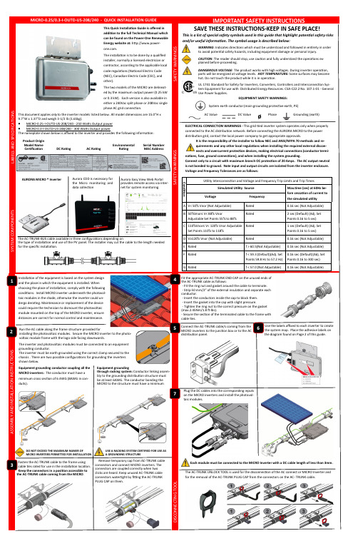
System earth conductor (main grounding protective earth, PE)The Power The inverter will not begin to feed energy into the distribution grid until the association procedure of the CDD (Concentrator Data Device) has been com-pleted.INTERFACE PROTECTION SYSTEM AND DEVICE DOWNSTREAM OF THE INVERTER not include any electromechanical devices (relays, contactors, etc.) for automatic disconnection from The installation technician is responsible for selecting a junction box with the appropriate dimensions and insulation. Do not to reverse the phase with the neutral!Choose the installation location of the CDD to configure the WiFi network and acquire the Micro Inverter. It is advisable NOT to fix the CDD to the wall in order to evaluate the placement based on the signal range. Configure the Wi -Fi device (via display on CDD), or connect the Associate the installed Micro Inverters on the CDD and select home networks for installation via wizard on the web server .Register at the Power -One AURORA Easy View web portal.Permanently mount the CDD to the wall. Consult the Instruction Manual for Aurora CDD operations and commissioning (found on the Power -One web page).Italy FacilityVia S. Giorgio, 64252028 Terranuova Bracciolini Italy +39 055 9195 1Camarillo Facility The purpose of the system map is to identify the inverter relative to its placement below the PV panel. The label affixed to the system map includes the identifying Serial Number. The CDD will display the production and other information based on the Serial Number.。

SPECIFICATIONSFX Form FactorSST-SX550550W Switching Power SupplyWith Active PFC 80Plus Gold01This is the specification of Model SX550; AC-line powered switching power supply with active PFC (Power Factor Correction) circuit, meet EN61000-3-2 and with Full Range Input features.The specification below is intended to describe as detailedly as possible the functions and performance of the subject power supply. Any comment or additional requirements to this specification from our customers will be highly appreciated and treated as a new target for us to approach.The subject power supply will meet the EMI requirements and obtain main safety approvalsas following:- FCC Part 15 Subpart J, Class ‘B’ 115 Vac operation.- CISPR 22 Class ‘B’ 230 Vac operation.2.1 EMI REGULATORY1. GENERAL DESCRIPTION AND SCOPE2. REFERENCE DOCUMENTS3. PHYSICAL REQUIREMENTS3.1 MECHANICAL SPECIFICATIONSThe mechanical drawing of the subject power supply, which indicate the form factor, location of the mounting holes, location, the length of the connectors, and other physical specifications of the subject power supply. Please refer to the attachment drawing.4. ELECTRICAL REQUIREMENTS4.1 OUTPUT ELECTRICAL REQUIREMENTSThe subject power supply will meet all electrical specifications below, over the full operation temperature range and dynamic load regulation.4.1.1. OUTPUT RATING(1)The +3.3V and +5V total output shall not exceed 120W(2) total output for this subject power supply is 550 watts.(3) Ripple and noise measurements shall be made under all specified load conditions through a singlepole low pass filter with 20MHz cutoff frequency. Outputs shall bypassed at the connector witha 0.1uF ceramic disk capacitor and a 10uF electrolytic capacitor to simulate system loading.02115V / 60Hz : 15 mSec. Minimum.230V / 50Hz : 15 mSec. Minimum.4.1.5.OVER VOLTAGE PROTECTION03The cross regulation defined as follows, the voltage regulation limits DC include DC Output ripple & noise.115V / 60Hz : 15 mSec. Minimum.230V / 50Hz : 15 mSec. Minimum.(10% TO 90% OF FINAL OUTPUT VALUE, @FULL LOAD)115V-rms or 230V-rms + 5Vdc : 20ms Maximum4.1.3. HOLD-UP TIME (@80 % LOAD)4.1.4.OUTPUT RISE TIME4.1.2. LOAD CAPACITY SPECIFICATIONS04P.G. SENSE Output short circuit is defined to be a short circuit load of less than 0.1 ohm.In the event of an output short circuit condition on +3.3V, +5V or +12V output, the power supply will shutdown and latch off without damage to the power supply. The power supply shall return to normal operation after the short circuit has been removed and the power switch has been turned off for no more than 2 seconds.In the event of an output short circuit condition on -12V output, the power supply will not be damaged. The power supply shall return to normal operation as soon as the short circuit has been removed. and the power switch has been turned off for no more than 2 seconds.The power good signal is a TTL compatible signal for the purpose of initiating an orderly star-up procedure under normal input operating conditions. This signal is asserted (low) until +5Vdc has reached 4.75 volts during power up. Characteristics:TTL signal asserted (low state) : less than 0.5V while sinking 10mA.TTL signal asserted (high state) : greater than 4.75V while sourcing 500uA. High state output impedance : less or equal to 1Kohm from output to common.4.1.6.SHORT CIRCUIT PROTECTION4.1.7.OVER CURRENT PROTECTION4.1.8.POWER GOOD SIGNALPOWER GOOD @ 115/230V,FULL LOAD POWER FAIL @115/230V, FULL LOAD100 – 500mSec.1 mSec. minimum05IAIB4.2. OUTPUT TRANSIENT LOAD RESPONSEV+5V and +12V must be within specification for a step change in current as specified below. The outputs will be tested one section at a time with all other sections at maximum load. The testtransition will be from IA to IB and IB to IA. The step current will have a nominal transition time of 0.5 amp per microsecond for +5V and 0.1 amp per microsecond for +12V.+5Vdc:IA: 16.0 amps IB: 11.2 ampsVolts variation: 400 mV max (p-p) Setting time: 10 ms max+12V:IA: 45.0 amps IB: 31.5 ampsVolts variation: 550 mV max (p-p) Setting time: 10 ms max +3.3Vdc:IA: 16.0 amps IB: 11.2 ampsVolts variation: 400 mV max (p-p) Setting time: 10 ms max4.2.1 Transient Load Requirement4.3. INPUT ELECTRICAL SPECIFICATIONS4.3.1. VOLTAGE RANGEPARAMETER UNITSV-in Range 90 - 264 V-rms4.3.2. INPUT FREQUENCYINPUT FREQUENCY 47–63Hz4.3.3. INRUSH CURRENT(Cold start – 25 deg. C)115V 60A230V 120A4.3.4. INPUT LINE CURRENT115V 8.0 Amps – rms maximum230V 4.0 Amps – rms maximum4.4. EFFICIENCYFull load (100%) Typical load (50%) Light load (20%) 115VAC 87% 90% 87%(loading shown in Amps)064.5. Standby Power Consumption (5Vsb):Input Power < 0.5W @ 5Vsb/45mA & 230Vac inputPS_ON input signal @ High State4.6. PS_ ON#PS_ON# is an active-low, TTL-compatible signal that allows a motherboard to remotely controlthe power supply in conjunction with features such as soft on/off, Wake on LAN+, or wake-on-modem.When PS_ON# is pulled to TTL low, the power supply should turn on the five main DC outputrails: +12VDC,+5VDC,+3.3VDC,and –12VDC. When PS_ON# is pulled to TTL highor open-circuited, the DC output rails should not deliver current and should be held at zeropotential with respect to ground. PS_ON# has no effect on the +5VSB output, which is always enabled whenever the AC power is present. Table 15 lists PS_ON# signal characteristics.The power supply shall provide an internal pull-up to TTL high. The power supply shall also provide debounce circuitry on PS_ON# to prevent it from oscillating on/off at startup when activated by a mechanical switch. The DC output enable circuitry must be SELV-compliant.Table 15. PS_ON# Signal Characteristics5. ENVIRONMENTAL REQUIREMENTSThe power supply will be compliant with each item in this specification for the following Environmental conditions.5.1. TEMPERATURE RANGEOperating 550W 0 to 50Storage -20 to 805.2. HUMIDITYOperating 5 –85% RH, Non-condensing Storage 5 –95% RH, Non-condensing075.3. VIBRATIONThe subject power supply will withstand the following imposed conditions without experiencingnon-recoverable failure or deviation from specified output characteristics.Vibration Operation, 0.01g²/Hz at 5 Hz sloping to 0.02g²/Hz at 20 Hz, and maintaining 0.02g²/Hz from20 Hz to 500 Hz. The area under the PSD curve is 3.13gRMS. The duration shall be 20 minutes per axisfor all three axes on all samples.Plane of vibration to be along three mutually perpendicular axes.5.4. SHOCKThe subject power supply will withstand the following imposed conditions without experiencingnon-recoverable failure or deviation from specified output characteristics.Storage 40G, 9 mSec. half-sine wave pulse in both directions on three mutually Perpendicular axes.Operating 10G, 11mSec. half-sine wave pulse in both directions on three mutually Perpendicular axes.6. SAFETYLEAKAGE CURRENTThe leakage current from AC to safety ground will not exceed 3.5 mA-rms at 264Vac, 50 Hz.7. ELECTORMAGNETIC COMPATIBILITY7.1. RADIATED EMIThe subject power suppy will meet FCC and CISPR 22 requirements under normal load conditions.0810.1 Physical Dimension09125 mm (W) × 63.5 mm (H) × 100mm (D)10. MECHANICAL REQUIREMENTS9.1. MTBF8.1. MODEL NUMBER LABEL8.2. DC OUTPUT IDENTIFICATIONCThe power supply have a minimum predicted MTBF(MIL-HDBK-217) of 100,000 hours ofcontinuous operation at 25 , maximum-output load, and nominal AC input voltage.Label marking will be permanent, legible and complied with all agency requirements.Labels will be affixed to the sides of the power supply showing the following:Each output connector will be labeled.- Manufacturer’s name and logo.- Model no., serial no., revision level, location of manufacturer.- The total power output and the maximum load for each output.- AC input rating.8. LABELLING9. RELIABILITY。

NS-1010PI供电交换机产品手册广州安网通信技术有限公司版权声明安网通信©2019安网通信版权所有,并保留对本手册及本声明的一切权利。
未得到安网通信的书面许可,任何人不得以任何方式或形式对本手册内的任何部分进行复制、摘录、备份、修改、传播、翻译成其他语言、将其全部或部分用于商业用途。
免责声明本手册内容依据现有信息制作,由于产品版本升级或其他原因,其内容有可能变更。
安网通信保留在没有任何通知或者提示的情况下对手册内容进行修改的权利。
本手册仅作为使用指导,安网通信在编写本手册时已尽力保证其内容准确可靠,但并不确保手册内容完全没有错误或遗漏,本手册中的所有信息也不构成任何明示或暗示的担保。
一、产品介绍产品图片NS-1010PI供电交换机提供10个10/100M自适应的RJ45端口,同时端口1~端口8具备PoE供电功能,可作为以太网供电设备。
端口1~端口8能自动检测识别符合IEEE802.3at/af标准的受电设备,并通过网线为其供电。
因而不需要担心会损坏私有标准的POE或非POE设备。
另外,当POE设备不连接时它会停止供电。
支持普通交换机供电100米或长距离供电250米传输。
NS-1010PI供电交换机是对想要经济的使用POE部署无线访问点(AP)和基于IP网络监控摄像头的小型商业网络的理想选择。
二、产品特性●遵循IEEE802.3以太网与IEEE802.3u快速以太网协议标准;●支持IEEE802.3at/af标准,兼容支持IEEE802.3at/af的受电设备(PD)●兼容符合已认证过的非标受电设备(PD)●支持普通POE交换机/VLAN隔离/250M传输等三种模式●提供10个10/100M自适应RJ45端口,其中端口1~端口8支持PoE供电;●所有端口均支持自动翻转(Auto MDI/MDI-X)功能●支持IEEE802.3X全双工流控与Backpressure半双工流控●所有端口均具备线速转发能力●支持MAC地址的自主学习与老化●全金属外壳,整机满载120W●即插即用三、技术参数硬件规格产品型号NS-1010PI(桌面型)背板带宽2Gbps网络接口8个10/100Mbps自适应电口(POE),2个10/100Mbps自适应上联电口(9、10口)LED指示灯Power指示灯红灯亮:正常POE指示灯绿灯亮:正常Link指示灯黄灯亮:正常电源输入AC输入100-240V、50/60H(内置电源)功耗标准IEEE802.3af/at单口最大功率30W,整机最大功率120WAI智能支持过流、过压、短路全保护支持大功率PD软启动支持顺序开机支持已认证的非标PD受电环境工作温度:-10°C~55°C存储温度:-40°C~70°C工作湿度:20%~85%(无凝结)存储湿度:10%~90%(无凝结)其他外形尺寸(长×宽×高):190mm*140mm*43mm(L*W*H)整机重量:约0.9kg软件功能转发模式存储转发协议支持IEEE802.3以太网介质访问控制协议IEEE802.3i10BASE-T以太网IEEE802.3u100BASE-TX快速以太网IEEE802.3af通过以太网数据线对或设备来实现以太网设备供电IEEE802.3at通过以太网数据线对或设备来实现以太网设备大功率供电IEEE802.3x流量控制传输速度100Mbps全双工,10or100Mbps半双工网络接口:10base-T或100base-TX以太网的RJ-45接口MAC表支持2K地址表管理模式拨码非管理型。

电源适配器技术规格承认书客户:产品型号: 5V1200MA类型:适配器版本号: A深圳市XXXX科技有限公司地址:联系人:电话:传真:1 适用范围此规格书用于规定适配器的电气、机械特性以及外部环境要求等各方面的规格。
2 存储条件3 电气特性3.1 输入特性3.1.1 电压/频率:输入电压范围是AC110V-240V,频率范围为47HZ-63HZ。
3.1.2 稳定电流(满载时):当输入交流电压AC90V–50/60HZ时,最大输入电流1000mA。
3.1.3 浪涌电流在冷开机的情况下,当输入230V电压后10uS内,最大浪涌电流小于27A。
3.1.4 空载消耗:240Vac输入,输出空载的情况下,输入功率小于1W。
3.1.5 最大功率:输出最大功率5W。
3.1.6 工作效率:在额定输入电压范围内和满载条件下,工作效率(输出功率/输入功率)≥ 50% 。
3.2 输出特性3.2.1 额定输出电压:DC5.0V3.2.1 输出电压范围:DC5.0V±0.5V3.2.3 输出电流范围:0.9~1.5A3.2.4 输出纹波:≤80mV(测试电路参考附图)测试方法:任何负载正常工作下,使用示波器带宽为20MHz连接到适配器的输出端,同时输出端并连一个104pF 陶瓷电容和一个10uF的电解电容。
3.2.5 起机延迟:输入额定电压后,该充电器应该在 100mS以内输出正常。
3.2.6 保持时间:断开交流输入,该适配器能保持输出电压在5.0V±0.5V以内,时间大于5mS(测试条件:240Vac输入,满载)。
3.3 保护电路3.3.1 短路保护能保证本产品在输出端短路状态下不会导致着火或任何损坏。
短路电流应不大于1000mA。
3.3.2 过温度保护当本产品内部温度过高时,内部过温度保护电路动作,使温度降低,不得出现着火或任何破坏。
4 环境适应性试验4.1 高温测试实验温度为65℃±2℃,产品不包装,持续实验时间为8小时。

电源技术规格书(客户承认书)SPECIFICATION FOR APPROV AL客户/ CUSTOMER: 光电显示客户物料号/CUSTOMER NO.:长城型号/ MODEL NO.: XSP200WV42B长城料号/ P/N .: 5171915电源版本/ POWER REV.: V01日期/ DATE: 2020.02.27客户确认签字,盖章后请回传一份承认书给我司。
Please return to us on copy of “SPECIFICATION FOR APPROV AL”with your approved signature.中国长城科技集团股份有限公司电源事业部China Greatwall Technology Group Co., LTD. Power Supply Division深圳宝安区石岩镇宝石东路长城工业园Great wall Industry Park, Baoshi East Rd, Shiyan Country, Baoan, ShenzhenTEL: 0755--29519374 / 26639997 FAX: 0755--29519395/power变更记录目录总则 (2)1 电气特性 (2)1.1输入特性 (2)1.1.1输入基本特性 (2)1.1.2输入保护特性 (2)1.2 输出特性 (2)1.2.1输出基本特性 (2)1.2.2输出保护特性 (3)1.2.3负载/温度曲线图&负载/输入电压曲线图 (3)2 环境 (4)3 电磁兼容性 (4)4 安规 (4)5 可靠性 (4)6 特殊要求 (4)7 外观结构 (5)7.1电源尺寸 (5)7.2标签图 (6)8 包装 (6)8.1电源净重 (6)8.2包装图 (6)8.3包装运输实验 (7)9条形码label说明 (7)10 使用注意事项 (8)10.1开箱检查 (8)10.2使用原则 (8)10.3安全注意事项 (8)11 产品保修 (8)11.1保修期限 (8)11.2维修范围 (8)11.3限制条款 (9)12 备注 (9)总则该款产品为AC转DC电源,90~264Vac交流输入,单路直流隔离输出,输出总功率168W,通过CCC、CE、UL认证,符合欧盟RoHS指令。

用户手册Rev1.0系列可编程交流电源用户手册版权所有翻印必究如有变更恕不通知目录1.联系我们 (25)2.保修与安全信息 (26)2.1有限售后保证 (26)2.2安全 (28)2.3安全规则 (28)2.4安全标识的含义 (28)2.5安全信息 (29)2.6安全注意事项 (31)3.产品概述 (39)3.1一般说明 (39)3.2产品特点 (40)13.3功能方框图 (41)3.4操作描述 (42)3.5测量与数据 (42)3.6附件 (42)3.7远程控制扩展接口 (43)4.技术规格 (45)4.1产品型号 (45)4.2技术规格 (46)4.3外形尺寸 (55)4.4输出电压与电流曲线 (56)4.5输出电压与频率曲线 (58)4.6输出电压THD与功率 (61)24.7输出电压THD与频率曲线 (62)4.8输出电压频率与功率曲线 (62)4.9输出电压精度与频率 (65)4.10谐波幅值误差与谐波次数关系曲线 (66)4.11直流模式输出功率曲线 (69)4.12输入电压与输出功率降额曲线 (71)4.13输出过流保护延迟曲线 (71)4.14环境 (72)4.15输出降额与环境温度 (73)4.15.1音频噪声与环境温度 (74)4.15.2音频噪声与输出功率 (75)4.15.3音频噪声与输出频率 (76)34.16安规及认证 (77)5.开箱和安装 (78)5.1检查 (78)5.2搬运说明 (79)5.3检查交流输入 (80)5.4交流输入连接 (80)5.5接地要求 (83)5.5.1机壳接地 (83)5.5.2输出中点接地 (84)5.6输入开关 (85)5.7桌面使用 (86)5.8通风 (87)45.9噪声水平 (87)5.10液体防护 (88)5.11清洁 (88)5.12负载连接 (89)5.12.1输出接线和建议线径 (89)5.12.2三相Y形负载连接 (90)5.12.3三相Δ形负载连接 (92)5.12.4单相/直流负载连接 (94)5.13远端补偿连接 (96)5.14异常状况处理 (96)6.前操作面板 (97)6.1前面板布局 (97)56.2开机/关机/复位按钮及操作 (99)6.2.1待机状态指示 (99)6.2.2开机状态指示 (101)6.2.3故障状态指示 (102)6.3输出使能按钮 (103)6.3.1输出状态指示 (103)6.3.2输出时序 (104)6.3.3输出响应时间 (104)6.4菜单键 (105)6.4.1测量键(MEAS) (105)6.4.2编程键(PROG) (106)6.4.3配置键(CONF) (107)66.4.4系统键(UTIL) (108)6.5功能键 (109)6.5.1方向键 (110)6.5.2返回键 (110)6.5.3确认键(OK) (110)6.5.4翻页键 (110)6.6数字键 (111)6.6.1数字键 (111)6.6.2取消键 (111)6.6.3消除按键 (111)6.6.4回车键 (112)6.7飞梭 (112)76.7.1电压飞梭旋钮 (112)6.7.2频率飞梭旋钮 (112)7.显示屏 (113)7.1测量 (113)7.1.1测量页面 (120)7.1.2电压页面 (121)7.1.3电流页面 (124)7.1.4功率页面 (127)7.1.5谐波页面 (128)7.2配置 (131)7.2.1稳态参数页面 (131)7.2.2输出设置页面 (137)87.2.3保护设置页面 (138)7.2.4波形数据页面 (139)7.2.5校准页面 (142)7.3编程 (149)7.3.1暂态List页面 (150)7.3.2暂态Pulse页面 (155)7.3.3暂态Step页面 (159)7.3.4谐波页面 (165)7.3.5间谐波页面 (167)7.3.6编程数据页面 (171)7.3.7触发设置页面 (178)7.4系统 (180)97.4.1通讯设置页面 (180)7.4.2参数存取页面 (184)7.4.3扩展设置页面 (186)7.4.4本地设置页面 (187)7.4.5系统信息页面 (189)8.后面板 (190)8.1输入连接器 (190)8.2输出连接器 (191)8.2.1电缆尺寸 (192)8.2.2连接步骤 (193)8.3接地端子 (193)8.4线缆固定 (194)108.5远端补偿接口 (194)8.6多功能接口 (195)8.6.1触发终端 (196)9.远端控制 (199)9.1概述 (199)9.2通信规约 (199)9.2.1常用符号 (199)9.2.2参数格式 (201)9.2.3SCPI指令介绍 (202)9.2.4执行次序 (206)9.3共同指令 (206)9.4仪器指令 (209)119.4.1测量指令 (209)9.4.2编程指令 (230)9.4.3设置指令 (260)9.4.4系统指令 (302)9.4.5状态指令 (306)9.4.6输出指令 (309)9.4.7触发指令 (310)9.4.8初始化指令 (314)9.5SCPI指令树 (316)10.附录1-内置谐波示例 (324)11.附录2-编程示例 (332)11.1电压暂降示例 (332)1211.2电压短时中断示例 (339)11.3短期供电电压变化试验示例 (341)13图1断开交流电源后的交流输入滤波器剩余电压检查示意图 (35)图2PAC系列功能框图 (41)图3PAC0115~PAC0315外型尺寸图 (55)图4恒功率曲线图 (57)图5PAC0115三相模式下单相输出电压与输出功率的关系 (59)图6PAC0215三相模式下单相输出电压与输出功率的关系 (60)图7PAC0315三相模式下单相输出电压与输出功率的关系 (61)图8输出频率与输出电压THD百分比关系 (62)图9PAC0315恒功率条件下输出电压与输出电流的关系 (63)图10输出频率与输出功率关系15 u-70 u (64)图11输出频率与输出功率关系70 u-5000 u (65)图1250/60 u谐波幅值误差与次数的关系 (67)14图13400 u谐波幅值误差与频次关系 (68)图14直流恒压模式下输出电压与输出电流关系 (70)图15降额曲线—输入电压 (71)图16过流保护延迟曲线 (72)图17温度与输出功率曲线 (74)图18环境温度与噪声曲线 (75)图19输出功率与噪声曲线 (76)图20PAC包装拆解示意图 (79)图21后面板接口说明图 (82)图22输出中点接地示意图 (85)图23输入开关图 (86)图24Y形负载连接示意图 (91)15图25Δ形负载连接示意图 (93)图26单相/直流负接线示意图 (95)图27远端补偿连接示意图 (96)图28功能及区域分划图 (98)图29输入开关-开机状态 (100)图30开机/关机/复位按钮-待机状态 (100)图31开机过程示意图 (101)图32开机结束示意图 (102)图33接通状态示意图 (103)图34电源输出时序图 (104)图35测量首页面 (106)图36编程首页面 (107)16图37配置首页面 (108)图38设置首页面 (109)图39页面区域功能分布示图 (114)图40测量-测量页面 (120)图41测量-电压页面 (121)图42电压波形信息图 (122)图43测量-电流页面 (124)图44电流波形信息图 (125)图45测量-功率页面 (127)图46测量-谐波页面 (129)图47稳态参数页面 (131)图48三角波对称度波形示例 (134)17图49交流分量斜率示例 (135)图50输出摆率示例 (136)图51输出设置页面 (137)图52保护设置页面 (139)图53波形数据页面 (140)图54外部存储页面 (141)图55外部波形存储页面 (142)图56解锁校准页面 (143)图57校准页面 (144)图58校准电压零偏接线示意图 (145)图59校准电压增益接线示意图 (147)图60暂态List页面 (150)18图61暂态List页面-更多设置 (151)图62暂态Pulse-基波页面 (155)图63暂态Pulse-脉冲页面 (156)图64暂态Pulse页面-更多设置 (157)图65暂态Step-交流页面 (160)图66暂态Step-直流页面 (161)图67暂态Step-频率页面 (162)图68谐波页面 (165)图69谐波存储界面 (167)图70间谐波页面 (168)图71间谐波页面-更多设置 (169)图72编程数据-暂态List数据列表 (172)19图73编程数据-暂态Pulse数据列表 (173)图74编程数据-暂态Step数据列表 (174)图75编程数据-暂态谐波数据列表 (175)图76编程数据-间谐波数据列表 (176)图77编程数据-外部存储-暂态 (177)图78触发设置页面 (178)图79通讯设置-RS232 (180)图80通讯设置-LAN (182)图81通讯设置-USB (183)图82参数存取页面 (184)图83扩展设置页面 (187)图84本地设置页面 (188)20图85系统信息页面 (189)图86补偿线缆连接顺序及色标 (195)图87触发终端前面板功能划分 (196)图88触发终端后面板功能划分 (198)图89指令结构 (203)21表1附件名称及数量表 (43)表2PAC系列型号表 (45)表3PAC系列尺寸重量表 (46)表4技术规格总揽表 (47)表5PAC工作环境表 (73)表6测量级页面快捷键功能 (115)表7电源故障信息 (116)表8电源状态信息表 (116)表9数据栏数值颜色含义 (118)表10电压波形信息计算方法表 (122)表11电流波形信息计算方法表 (126)表12功率信息计算方法表 (127)22表13谐波显示次数与频率的关系 (129)表14谐波显示数据范围表 (130)表15波形类型与频率范围关系表 (132)表16交流(V)与工作频率范围关系表 (152)表17有效值模式说明表 (154)表18交流(V)与工作频率范围关系表 (158)表19有效值模式说明表 (159)表20有效值模式说明表 (164)表21工作频率与可设谐波次数的关系 (166)表22输出连接器连接数据限值表 (192)表23编程指令的数字格式 (201)表24可用的共同指令 (206)23表25可用的SCPI子系统指令 (209)表26触发执行指令发送方式 (233)表27谐波编程电源设置 (254)表28电源输出频率与可设谐波次数间的关系 (254)表29电源输出频率与交流电压给定范围间的关系 (266)241.联系我们地址:中国·陕西·西安新型工业园区信息大道12号邮编:710119电话:+86(029)856918708569187185691872传真:+86(029)85692080网址:邮箱:******************252.保修与安全信息2.1有限售后保证西安爱科赛博电气股份有限公司对所制造及销售的PAC产品自交货之日起一年内,保证正常使用情况下产生故障或损坏,负责免费维修。

产品特点▶宽压输入85~265VAC,100~370VDC,47~400Hz▶高可靠性,高精度稳压输出,低纹波噪声▶额定功率7W,最大峰值功率10W▶空载功耗低至0.15W,满载效率范围80%~85%▶满足单路/双路隔离输出,隔离耐压≥2500VAC▶输出过流保护,输出短路保护自恢复▶工作温度:-40℃~+85℃▶通过CE认证;需求RoHS 标准下单时注明▶CE-EMC: B-E191227382▶CE-LVD: B-E191227383应用范围▶TA10 W2系列电源是一款小体积交直流两用电源模块,主要应对物联网市场要求体积小峰值功率大的特点开发的,输入范围85~265VAC,100~370VDC,满载使用功率7W,最大动态峰值功率达10W,适用于体积要求小负载动态变化大的应用场景; 空载功耗低至0.15W,效率范围80%~85%;满足单路/双路隔离输出,隔离耐压≥2500VAC; 工作温度-40℃~+85℃,满载使用时要求有良好的散热条件;输入欠压保护,过流保护,输出短路保护自恢复。
▶该系列广泛应用于物联网、AI设备、智慧城市、新能源、仪器仪表、办公及民用等行业中。
▶当应用有较高电磁兼容要求时,须参考本系列产品的EMC外围应用电路。
输入特性项目 说明输入电压范围 85~265VAC输入频率范围 47~400Hz推荐保险管 1A慢熔保险管待机功耗 低至0.15W输出特性项目 说明输出电压精度Vo1≤±2%Vo2稳压输出≤±2%,Vo2非稳压输出≤±5%线性调整率 ≤0.5%负载调整率 ≤1%温度系数 ≤0.02%/℃短路保护 长期短路保护,自恢复过流保护 ≥120%一般特性项目 说明隔离电压 输入输出之间隔离≥2500VAC,双路输出之间隔离≥1000VDC 绝缘电阻 500VDC,≥100MΩ开关频率 典型65KHz工作温度范围 -40~85℃存储温度范围 -40~105℃存储湿度 ≤95%RH焊接温度 手工焊接350~400℃,时间≤5S 波峰焊接260±5℃,时间5~10S冷却方式 自然冷却 平均无故障工作时间 200000h 隔离电容 1000Pf 外壳材质及重量 塑壳,≈23gEMC特性EMI 传导骚扰 EN55011(CISPR11) / EN55032(CISPR32,CLASS B(需外配电路) 辐射骚扰 EN55011(CISPR11) / EN55032(CISPR32,CLASS BEMS静电放电 IEC/EN61000-4-2辐射抗扰度 IEC/EN61000-4-3脉冲群抗扰度 IEC/EN61000-4-4(需外配电路) 浪涌抗扰度 IEC/EN61000-4-5(需外配电路) 传导骚扰抗扰度 IEC/EN61000-4-6(需外配电路) 电压暂降、跌落和短时中断抗扰度IEC/EN61000-4-11典型应用图图1 一般应用电路图2 EMC 解决方案单路输出外部电路元器件的典型值产品型号\ 元件FUSEMOV1 CXLDMLCMCY1,CY2C1C2 TVS TAS10-5-W2 T1A/250V MOV 为压电阻,推荐值为10D471KCX 为X2安规电容,104K/275V ACLDM 为差模电感,推荐值为470uH~1mH/电流0.1A/内阻1Ω表贴电感,感值越大效果越好LCM 为共模电感,推荐值为10~30mHY1:102M/ 400VAC105K/50V(瓷片电容)根据实际情况选配470uF/16VP6KE6.8ATAS10-12-W2 220uF/25V P6KE15A TAS10-15-W2 220uF/25VP6KE18A TAS10-24-W2100uF/35VP6KE27A双路输出外部电路元器件的典型值图3 双路隔离输出典型应用降额曲线图结构图及引脚定义型号/引脚号 1 2 3 4 5 6 7 TASXX-XX-W2单路输出 N L NP Vo- NP Vo+ NP TADXX-XXXX-WI2双路隔离输出 N L Vo1- Vo1+ NP Vo2- Vo2+ TADXX-XX V XX-WI2双路隔离输出 N L Vo1- Vo1+ NP Vo2- Vo2+备注:NP为无管脚,NC为空管脚包装信息:一盒40只,一箱15盒共600只。

INTERFACE创新电源——系统的可靠保证菲尼克斯电气中国公司地址:南京市江宁开发区菲尼克斯路36号南京江宁236信箱电话:(025)52121888传真:(025)52121555/800 8289722邮编:211100h t t p: //e-mail: phoenix@ CN 11/12 INTERFACE 创新电源TNR 5768710/10.2011-01 Printed In China© PHOENIX CONTACT2011突破性技术——电源解决方案创新促进发展。
菲尼克斯电气的电源产品无疑印证了这一宗旨。
在对理想的电源探索中,我们洞悉市场,与客户密切合作,坚持与执着,不断创造出卓越的新产品技术。
我们的目标是最大程度提高您的设备和系统的可用性。
QUINT电源提供最优产品功能,三个新产品系列在各自领域里树立了新的标杆。
新产品采用ACB技术的冗余模块ACB(自动电流平衡)技术可使您的冗余电源系统的使用寿命翻倍。
该技术确保一定范围内所有的电源平衡输出。
QUINT ORING冗余模块的ACB技术还可检测临界工作状态,并为您提供提前预警。
新产品采用IQ技术的不间断电源具有持续电池监控和智能管理功能的IQ技术可随时为您提供电池的充电状态、剩余工作时间和使用寿命等相关信息。
智能通信功能将预警您危险工况的出现。
这可减少维护工作量,提升系统可用性。
新产品采用SFB技术的DC/DC变换器SFB(选择性触发)技术可在一旦输出回路出现短路时,可靠地切断故障回路。
在短路情况下,将能提供6倍额定输出电流,维持12ms时间。
因此,SFB技术能够可靠地触发标准断路器。
您可快速地进行故障定位,并确保系统的重要设备继续工作。
——采用SFB技术为系统有效性提供最高保证新一代紧凑型QUINT电源,将最大程度地保证系统的有效性。
该电源采用SFB技术(选择性触发技术),能在12ms内输出6倍的额定电流,可靠快速地触发标准断路器脱扣。
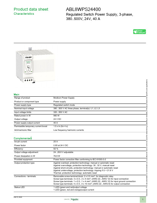
Product data sheetCharacteristicsABL8WPS24400Regulated Switch Power Supply, 3-phase,380..500V, 24V, 40 AMainRange of productModicon Power Supply Product or component type Power supplyPower supply type Regulated switch modeNominal input voltage 380...500 V AC three phase, terminal(s): L1, L2, L3Input voltage limits 320...550 V AC Rated power in W 960 W Output voltage24 V DC Power supply output current 40 APermissible temporary current boost 1.5 x In (for 4 s)Anti-harmonic filterLow frequency harmonic currentsComplementaryInrush current 25 APower factor 0.85 at 24 V DC Efficiency92 %Output voltage adjustment 24...28.8 V adjustable Power dissipation in W 76.8 WProvided equipment Power factor correction filter conforming to IEC 61000-3-2Output protection typeAgainst overload, protection technology: manual or automatic reset Against overvoltage, protection technology: 30...32 V, manual reset Against short-circuits, protection technology: manual or automatic reset Against undervoltage, protection technology: tripping if U < 21.6 V Thermal, protection technology: automatic resetConnections - terminalsRemovable screw terminal block: 2 x 2.5 mm², for diagnostic relayScrew type terminals: 3 x 0.5...3 x 4 mm², (AWG 22...AWG 12) for input connectionScrew type terminals: 1 x 0.5...1 x 4 mm², (AWG 22...AWG 12) for input ground connection Screw type terminals: 4 x 0.5...4 x 10 mm², (AWG 22...AWG 8) for output connection Status LED1 LED (green and red)output voltage1 LED (green, red and orange)output currenti s c l a i m e r : T h i s d o c u m e n t a t i o n i s n o t i n t e n d e d a s a s u b s t i t u t e f o r a n d i s n o t t o b e u s e d f o r d e t e r m i n i n g s u i t a b i l i t y o r r e l i a b i l i t y o f t h e s e p r o d u c t s f o r s p e c i f i c u s e r a p p l i c a t i o n sDepth160 mmHeight143 mmWidth166 mmNet weight 2.7 kgOutput coupling ParallelSeriesMarking CEMounting support35 x 7.5 mm symmetrical DIN rail35 x 15 mm symmetrical DIN railOperating position VerticalEnvironmentStandards CSA C22.2 No 60950-1UL 508Product certifications CCSAusEACULRCMEnvironmental characteristic EMC conforming to EN 61000-6-1EMC conforming to EN 61000-6-3EMC conforming to EN 55024EMC conforming to EN/IEC 61000-6-4EMC conforming to EN/IEC 61204-3Safety conforming to EN 61204-4Safety conforming to EN/IEC 60950-1Safety conforming to SELVOperating altitude2000 mIP degree of protection IP20 conforming to EN/IEC 60529Ambient air temperature for operation50…60 °C (with derating factor)-25…50 °C (without)Ambient air temperature for storage-40…70 °CRelative humidity0…90 % during operation0…95 % in storageDielectric strength3500 V between input and ground4000 V between input and output500 V between output and groundPacking UnitsPackage 1 Weight 3.325 kgPackage 1 Height 1.960 dmPackage 1 width 1.600 dmPackage 1 Length 1.860 dmOffer SustainabilitySustainable offer status Green Premium productREACh Regulation REACh DeclarationEU RoHS Directive Pro-active compliance (Product out of EU RoHS legal scope)EU RoHS DeclarationMercury free YesRoHS exemption information YesChina RoHS Regulation China RoHS declarationEnvironmental Disclosure Product Environmental ProfileCircularity Profile End of Life InformationPVC free YesContractual warrantyWarranty18 monthsDimensions DrawingsRegulated Switch Mode Power Supplies DimensionsRegulated Switch Mode Power Supply Internal Wiring DiagramRegulated Switch Mode Power SupplyLine Supply Wiring DiagramThree-phase (L1-L2-L3) 3 x 380 to 500 VRegulated Switch Mode Power SuppliesSeries or Parallel ConnectionSeries Connection(1)Two Shottky diodes Imin = power supply In and Vmin = 50 VParallel ConnectionNOTE: Series or parallel connection is only recommended for products with identical references.For better availability, the power supplies can also be connected in parallel using the ABL8RED24400 Redundancy module.Regulated Switch Mode Power SuppliesDeratingThe ambient temperature is a determining factor that limits the power an electronic power supply can deliver continuously. If the temperature around the electronic components is too high, their life will be significantly reduced.The nominal ambient temperature for the Universal range of Phaseo power supplies is 50°C. Above this temperature, derating is necessary up to a maximum temperature of 60°C.The graph below shows the power (in relation to the nominal power) that the power supply can deliver continuously, depending on the ambient temperature.X Maximum operating temperature (°C)ABL 8RPM, ABL 8RPS, ABL 8WPS mounted verticallyDerating should be considered in extreme operating conditions:●Intensive operation (output current permanently close to the nominal current, combined with a high ambient temperature)●Output voltage set above 24 Vdc (to compensate for line voltage drops, for example)●Parallel connection to increase the total powerRegulated Switch Mode Power SupplyLoad LimitManual Reset Protection Mode(1)Boost 4sAutomatic Reset Protection Mode(1)Boost 4s“Boost” Repeat AccuracyThis type of operation is described in detail in the user manual, which can be downloaded from the website.。
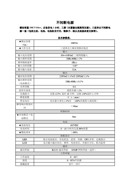
不间断电源额定容量20KV/16kw、后备供电2小时、工频(内置输出隔离变压器)、三进单出不间断电源一套(包括主机、电池、电池柜含开关、铜鼻子、线以及底座承重支架等)。
技术参数表:★额定容量20KVA(VA)★工作方式三进单出工频双变换在线式输入输入电压范围304~456V AC三相四线输入输入频率范围50Hz/60Hz±5%频率跟踪速率1Hz/s输入功率因数﹥0.97最大输入电流32A输出输出电压范围220V AC±1%或230V AC±1%输出频率范围50Hz/60Hz±0.5%(电池模式)功率因数0.8波形失真度线性负载<1%过载能力过载125% 延时10分钟,过载150%延时1分钟峰值系数3∶1(max)暂态电压电压最大变化±4%内(100%负载投入或切离)瞬变响应恢复时<40ms间转换时间★市电模式→电0ms池模式电池★直流电压192VDC充电时间8~10小时内完成90%容量★整机效率>90%面板显示LED 指示电池低压,市电状态,逆变,旁路,UPS异常,过载指示LCD 显示输入输出电压,频率,电池电压,负载百分比,机内温度通讯通讯界面RS232通讯界面SNMP网络界面(选件)工作环境工作温度0~40℃湿度0~95%不结露储藏温度-25℃~55℃噪音<55dB(距箱体1米处)物理特性净重(Kg)297毛重(Kg)337尺寸(W×D×H)mm725×430×1180执行标准YD/T1095-2008蓄电池★后备延时时间(满载)≥2小时有效容量开始使用100%使用1~2年90%使用4年后70~80%自放电速率25℃存放12个月,容量>60% 深充深放循环次数100%,≥180次可存放时间>4个月深度放电保护具备电池状态检测具备电池放电实时监测及显示具备充电时间8小时之内充到电池容量的90%电池保护具备厂商项目授权书、质保承诺函要求提供厂家设备服务承诺书原件(承诺本项目的整套设备的质保期为三年免费);要求提供针对本项目的厂家授权书原件。


大连泰思曼科技有限公司高压电源用户手册型号:TXR1010大连泰思曼科技有限公司地址:大连市高新园区火炬路1号电话:86-411-8475462286-411-8475472286-411-84754522传真:86-411-84754122电子邮件:sales@.网址: X-光机专用高压电源50W,25KV至● 输出电压从25KV 到65KV ● 集成可调的灯丝电源 ● 过压和输出短路保护 ● 电压和电流调节功能 ● 可遥控调节发射电流 ● 安全的互锁功能● 可根据用户要求订制发射电流控制: 泰思曼TXR1010系列高压电源是X 光机专用电源,它集成了输出直流电压5.5V 电流0.3A 到3A 可调的灯丝电源。
高压和灯丝电流可实现线性平稳上升。
TXR1010系列电源还可外接电位器实现输出电压和电流的远程控制,并且具有外接电压和电流显示、高压输出端过压和短路保护、安全互锁等功能。
电源内部:电源自带的多圈电位器可将电子束电流设置在0A 到最高电流。
外部遥控:外部0到10V 控制信号可将电子束电流设置在0A 到最高电流。
直流灯丝电源:输出电流为3.5A 可调,电压为5.5V 。
电压调整率:典型应用: 相对负载:0.01%(空载到额定负载)。
相对输入:±0.01% (输入电压变化为±10%)。
Kevex, Oxford, RTW, Superior, Varian andTrufocus 等品牌的阴极接地的X 光射线管。
电流调整率: 相对负载:0.01%(空载到额定负载)相对输入:±0.01% (输入电压变化±10%)。
可选功能: 纹波电压:输出额定电压条件下,纹波电压的峰峰值为最高输出电压的0.25%。
AC 交流灯丝电源 环境温度:工作时0到+50℃,CPC 恒功率输出 储存时-20℃到+80℃。
温度系数:每摄氏度0.01%。
规格说明: 稳定度:开机半小时后每8小时小于0.05%。

Quick Start PowerLINE WiFi 1000 Essentials EditionModels PL1010v2 and PLW1010v2Package ContentsIn some regions, a resource CD is included with your product.Get StartedPowerLINE adapters give you an alternative way to extend your network using your existing electrical wiring. Plug two or more PowerLINE adapters into electrical outlets to create a wired network connection. Use a PowerLINE WiFi access point to add a WiFi access point to your wired network. You can add up to eight adapters to extend your network.Meet Your AdaptersBefore you install your adapters, familiarize yourself with their LEDs, buttons, and ports.121. Power LED 4. Ethernet port7. WiFi LED2. Ethernet LED 5. Factory Reset button8. On/Off switch3. Pick A Plug LED 6. Security button9. WPS button 815234569 7Power LED Solid green. The electrical power is on.Solid amber. The adapter is in power saving mode (PL1010only).Blinking green. The adapter is in the process of setting upsecurity.Off. The adapter is not receiving electrical power. Ethernet LED Solid. The Ethernet port is linked.Off. No Ethernet connection is detected.Pick A Plug LED The Pick A Plug feature lets you pick the electrical outletwith the strongest link performance, indicated by the colordisplayed by the LED:Red. Link rate < 50 Mbps (good).Amber. Link rate > 50 and < 80 Mbps (better).Green. Link rate > 80 Mbps (best).Off. The adapter did not find any other compatiblePowerLINE devices using the same encryption key.WiFi LED Solid blue. The WiFi radio is on.Off. The WiFi radio is off.Factory Reset button Press the Factory Reset button for one second, and then release it to return the PowerLINE adapter to its factory default settings.Ethernet port Connect your wired devices, including computers, WiFirouters, and game consoles, to your PowerLINE network. Security button Use the Security button to create a secure PowerLINEnetwork.On/Off switch Use the On/Off switch to turn the device on and off.WPS button Use the WPS button to automatically connect your computer or other WiFi-enabled devices that support WPS to yourPowerLINE network.Install Your AdaptersNote: Do not plug your PowerLINE adapters into extension cords, power strips, or surge protectors.Room 1Room 2¾To install your adapters:1. Plug in your new adapters.2. Wait until the Pick A Plug LEDs are lit.3. Use your computer, tablet, or smartphone to connect to your newPowerLINE WiFi network. The WiFi SSID and key are printed on the adapter labels. The SSID is similar to Netgear##_EXT or Netgear##-5G_EXT.Congratulations. You installed your adapters and set up your network. You can customize the network and security settings later.Do MoreAfter your PowerLINE network is installed and running, you can use WPS to connect your access point, expand your network, customize the network settings, and customize security.Use WPS to Connect to Your Network¾To automatically connect to the PowerLINE access point using a WPS button:1. Press and hold the WPS button on the PowerLINE access point fortwo seconds and release it.The WiFi LED starts to blink.2. Press the WPS button on your WiFi device for two seconds andrelease it.When the WiFi LED stops blinking, your WiFi-enabled device isautomatically connected to the PowerLINE access point and you can surf the web.Add AdaptersTo add adapters before you configure the security feature, just plug them in and connect the adapters to your equipment. To add adapters after you configure the security feature, do the following:¾To add an adapter to a PowerLINE network with security set:1. Plug the adapter into a wall outlet where you want to add Internetaccess.2. If you used a private encryption key, press the Security button onone of the adapters that is already a part of the network for twoseconds, and then press the Security button on the new adapter for two seconds.Both buttons must be pressed within two minutes.Note: The Security button does not work in power saving mode.Do not press the Security button on the PowerLINE adapter until installation is complete and the adapters are communicating with each other (indicated by the blinking Power LED). Pressing this button too soon can temporarily disable PowerLINE communication. If this occurs, use the Factory Reset button to return the PowerLINE adapter to its factory default settings.Customize Your Network SettingsThe web browser setup guide helps you configure the WiFi settings of the PowerLINE.¾To change your settings:1. With your computer or WiFi device connected to your WiFi network,open a web browser.2. Navigate to the following address: .3. Follow the on-screen instructions.4. When prompted to log in, enter the user name admin and thepassword. The initial password is the same as the WiFi key password and is printed on the adapter label.You can record the new WiFi settings here:__________________________________________WiFi network name (SSID)___________________________________________Network key (passphrase)___________________________________________Customize Your Network SecurityWhen you first set up your network, the setup uses a default encryption key common to all PowerLINE adapters. You can change this and create a private secure network.¾To create a private secure network:1. Wait until the Pick A Plug LEDs are lit.2. Press the Security button for two seconds on one adapter, and thenpress the Security button on one of the other adapters for twoseconds. Both buttons must be pressed within two minutes. Note: The Security button does not work in power saving mode (see Troubleshooting Tips on page 13).Warning: Do not press the Security button on the PowerLINE adapter until installation is complete and the adapters are communicating with each other (indicated by the Power LED). Pressing this button too soon can temporarily disable PowerLINE communication. If this occurs, use the Factory Reset button to return the PowerLINE adapter to its factory default settings.If you add adapters later, use this procedure to add the new adapters to your secure network.Troubleshooting TipsPower LED is off.Make sure that power is supplied to the electricaloutlet, and that the PowerLINE devices are not pluggedinto an extension cord, power strip, or surge protector. Power LED is amber.Power saving mode occurs when the Ethernet LED isoff. This can occur in the following circumstances:• The Ethernet cable is unplugged.• The device that is connected through the Ethernetcable is turned off.• The adapter is idle for 10 minutes.It returns to normal mode within two secondsafter the Ethernet link is established.Pick A Plug LED is off.• If you already set network security, make surethat all PowerLINE devices are using the sameencryption key. For informtion, see the online usermanual.• Press the Factory Reset button on each devicefor one second to return the PowerLINE adapter toits factory default settings.Pick A Plug LED is amber or red.Something is interfering with communication between adapters. To resolve this, do the following:• Move the adapters to other outlets.• Unplug devices that might be causing interference such as surge suppressors and items with motors.Ethernet LED is off.• Make sure that the Ethernet cables are workingand securely plugged into the devices.• Press the Factory Reset button on each devicefor one second to return the PowerLINE adapter toits factory default settings.November 2019NETGEAR INTERNATIONAL LTD Floor 1, Building 3,University Technology Centre Curraheen Road, Cork,T12EF21, IrelandNETGEAR, Inc. 350 East Plumeria DriveSan Jose, CA 95134, USASupportThank you for purchasing this NETGEAR product. You can visit /support to register your product, get help, access the latest downloads and user manuals, and join our community. We recommend that you use only official NETGEAR support resources.Trademarks© NETGEAR, Inc., NETGEAR and the NETGEAR Logo are trademarks of NETGEAR, Inc. Any non‑NETGEAR trademarks are used for reference purposes only.ComplianceFor the current EU Declaration of Conformity, visit /app/answers/detail/a_id/11621.For regulatory compliance information, visit /about/regulatory/.See the regulatory compliance document before connecting the power supply.。

DAM10102继电器控制卡说明书V1.1北京聚英翱翔电子有限责任公司2015年01月目录一、产品特点 (1)二、产品功能 (1)三、产品选型 (1)四、主要参数 (1)五、接口说明 (2)六、接线方式 (2)1、RS485级联接线方式 (2)2、RS232接线连接方式 (3)七、输入输出接线 (3)1、继电器接线说明 (3)2、有源开关量接线示意图 (3)3、无源开关量接线示意图 (4)八、测试软件说明 (5)1、软件下载 (5)2、软件界面 (5)3、通讯测试 (6)九、参数及工作模式配置 (6)1、设备地址 (6)2、波特率的读取与设置 (7)3、闪开闪断功能及设置 (8)十、开发资料说明 (8)1、通讯协议说明 (8)2、Modbus寄存器说明 (9)3、指令生成说明 (10)4、指令列表 (11)5、指令详解 (12)十一、常见问题与解决方法 (14)十二、技术支持联系方式 (15)一、产品特点●DC7-30V;●继电器输出触点隔离;●通讯接口支持RS485或RS232;●通信波特率:2400,4800,9600,19200,38400(可以通过软件修改,默认9600);●通信协议:支持标准modbus RTU协议;●可以设置0-255个设备地址,5位地址拨码开关可以设置1-31地址码,大于31的可以通过软件设置;●具有闪开、闪断功能,可以在指令里边带参数、操作继电器开一段时间自动关闭;●具有频闪功能,可以控制器继电器周期性开关。
二、产品功能●10路光耦输入(5-24v),10路继电器输出,2路12位分辨率模拟量电压输入;●支持5位寻址地址;●支持波特率:2400,4800,9600,19200,38400。
三、产品选型型号modbus RS232RS485USB WiFi继电器DAM10102-RS232/485●●●10四、主要参数参数说明触点容量10A/30VDC10A/250VAC耐久性10万次数据接口RS485/RS232额定电压DC7-30V电源指示1路红色LED指示输出指示10路红色LED指示温度范围工业级,-40℃~85℃尺寸145*94*41mm重量330g默认通讯格式9600,n,8,1波特率2400,4800,9600,19200,38400,115200软件支持配套配置软件、控制软件;支持各家组态软件;支持Labviewd等五、接口说明六、接线方式1、RS485级联接线方式电脑自带的串口一般是RS232,需要配232-485转换器(工业环境建议使用有源带隔离的转换器),转换后RS485为A、B两线,A接板上A端子,B接板上B端子,485屏蔽可以接GND。

Eaton PDG24K0100E2NNEaton Power Defense molded case circuit breaker, Globally Rated, Frame 2, Four Pole (100% N), 100A, 50kA/480V, PXR20 LSI TU, No TerminalsGeneral specificationsEaton Power Defense molded case circuit breakerPDG24K0100E2NN 78667925420288.9 mm 152.4 mm 139.5 mm 2.46 kg Eaton Selling Policy 25-000, one (1) year from the date of installation of theProduct or eighteen (18) months from thedate of shipment of the Product,whichever occurs first.RoHS Compliant CCC MarkedIEC 60947-2UL 489CSAProduct NameCatalog Number UPCProduct Length/Depth Product Height Product Width Product Weight WarrantyCompliancesCertifications100 AComplete breaker 2Four-pole (100% N)PD2 Global Class A PXR 20 LSI600 Vac 600 V100% neutral protection No Terminals50 kAIC at 480 Vac10 kAIC Icu @125 Vdc10 kAIC Icu @250 Vdc25 kAIC @600V (UL/CSA)35 kAIC Icu/ 35 kAIC Ics/ 73.5 kAIC Icm @440V (IEC)30/25 kAIC Icu/ 15/13 kAIC Ics @525V South Africa (IEC)35 kAIC Icu/ 22.5 kAIC Ics/ 73.5 kAIC Icm @480V Brazil (IEC) 10 kAIC Icu/ 5 kAIC Ics/ 21 kAIC Icm @690V (IEC)50 kAIC @480V (UL)85 kAIC Icu/ 85 kAIC Ics/ 187 kAIC Icm @240V (IEC)50 kAIC Icu/ 50 kAIC Ics/ 105 kAIC Icm @380-415V (IEC)85 kAIC @240V (UL)100 A Eaton Power Defense MCCB PDG24K0100E2NN 3D drawingPower Xpert Protection Manager x64Power Xpert Protection Manager x32Consulting application guide - molded case circuit breakersPower Defense technical selling bookletPower Defense brochurePower Defense molded case circuit breaker selection posterPower Defense molded case circuit breakers - Frame 2 product aidMolded case circuit breakers catalogPower Xpert Release trip units for Power Defense molded case circuit breakersAmperage RatingCircuit breaker frame type FrameNumber of poles Circuit breaker type ClassTrip TypeVoltage rating Voltage rating - maxProtection TerminalsInterrupt rating Interrupt rating rangeTrip rating 3D CAD drawing package Application notesBrochuresCatalogsCertification reportsPDG2 CB reportEU Declaration of Conformity - Power Defense molded case circuit breakersPDG4 CCC certificationPDG4 CB reportInstallation instructionsPower Defense Frame 2 multi wire connector kit -PDG2X3(2)(4)TA2256W instructions - IL012242EN H01Power Defense Frame 2 PDG2 and PDC(E)9 breaker instructions -IL012106ENPower Defense Frame 2 shunt trip UVR instructions - IL012130EN Power Defense Frame 2 Bell Alarm Switch Instructions (IL012154EN).pdf Power Defense Frame 2 bell alarm switch instructions - IL012154EN Power Defense Frame 2/3/4/5/6 voltage neutral sensor module wiring instructions – IL012316ENPower Defense Frame 2 clamp terminal (steel), 20A, 4 pole instructions - IL012246EN H04Power Defense Frame 2 box terminal (aluminum), 225A, 4 pole instructions - IL012235EN H04Power Defense Frame 2 locking devices and handle block instructions - IL012149ENPower Defense Frame 1 IEC and Frame 2 Rotary Mechanism with NFPA Handle Attachment Instructions (IL012260EN).pdfPower Defense Frame 2 multi wire connector kit -PDG2X3(2)(4)TA2253W instructions - IL012243EN H01Power Defense Frame 2 screw terminal_end cap kit, 225A, 3 pole instructions - IL012258EN H01Power Defense Frame 2 box terminal (steel), 100A, 4 pole instructions - IL012234EN H04Power Defense Frame 1-2-3-4 IP door barrier assembly instructions -IL012278ENPower Defense Frame 2 tunnel terminal (aluminum), 100A, 4 pole instructions - IL012237EN H04Power Defense Frame 2 tunnel terminal kits - PDG2X1TA225K instructions- IL012239EN H01Power Defense Frame 2 terminal kit - PDG2X3(2)(4)TA225RF instructions - IL012245EN H01Power Defense Frame 2 tunnel terminal (aluminum), 150A, 4 pole instructions - IL012238EN H04Power Defense Frame 2 global terminal shield, 4 pole - IL012330EN Power Defense Frame 2 tunnel terminal (aluminum), 50A, 4 poleinstructions - IL012236EN H04Power Defense Frame 2 terminal kit - PDG2X3(2)(4)TA150RF instructions - IL012244EN H01Installation videosPower Defense Frame 2 TMTU Aux, Alarm, ST and UVR Animated Instructions.rhPower Defense Frame 2 Bell Alarm with PXR Animated Instructions.pdf.rh Power Defense Frame 2 withTMTU, Shunt Trip_UVR Animated Instructions.rhMultimediaPower Defense Frame 3 Variable Depth Rotary Handle Mechanism Installation How-To VideoPower Defense Frame 2 Direct Rotary Handle Mechanism Installation How-To VideoPower Defense Frame 2 Aux, Alarm, Shunt Trip, and UVR How-To Video Power Defense Frame 2 Variable Depth Rotary Handle Mechanism Installation How-To VideoPower Defense molded case circuit breakersPower Defense Frame 5 Trip Unit How-To VideoEaton Power Defense for superior arc flash safetyPower Defense BreakersPower Defense Frame 6 Trip Unit How-To VideoSpecifications and datasheetsEaton Specification Sheet - PDG24K0100E2NNTime/current curvesPower Defense time current curve Frame 2 - PD2White papersSingle and double break MCCB performance revisitedMolded case and low-voltage power circuit breaker healthIntelligent circuit protection yields space savingsIntelligent power starts with accurate, actionable dataMaking a better machineMolded case and low-voltage breaker healthSafer by design: arc energy reduction techniquesEaton Corporation plc Eaton House30 Pembroke Road Dublin 4, Ireland © 2023 Eaton. All Rights Reserved. Eaton is a registered trademark.All other trademarks areproperty of their respectiveowners./socialmedia。
可程式交流电源说明书型号WP-10101、输入电压:单相220V±10%2、输入频率:50Hz±5%或60Hz±5%3、输出电压:AUTO:0~300V(0-150V、150-300VZ自动切换)HV:0~300V4、电压设定:0-300V5、电压解析度:0.1V6、稳压率:<±0.5%7、频率设定:43.0-500.0Hz(0.1Hz/STEP)8、稳定率:<100PPM9、波形失真度:<1%10、额定容量:1000V A11、额定电流:0-150V 8.4.1A 0-300V 4.2A12、计时器设定:0.1S-999.9S13、电流上限设定:0.1A~8.4A14、具30组输出电压、频率等记忆功能15、功率因数:>0.816、自动程式记忆:可做10段不同测试值之连续测试17、启始角度设定:0-359°(1°/STEP)18、外规尺寸:W³D³H 单位:(MM)□420³175³50019、工作环境:温度0-40,湿度10%-90%。
20、保护装置:输入无熔丝开关,输出无熔丝开关电子式过载短路保护电路。
21、仪表规板:测试功能范围解析度精确度电压表0~300.0V 0.1V ±0.5%电流表0~100.00A 0.01A ±0.5%功率表0~10000W 1.0W ±1%频率表45.0~500Hz 0.1Hz ±0.1Hz测试时间0~999.9S 0.1S ±0.02S功率因数0.00~1.00 0.01 1%M O D E L :M O D E L V .S E T F .S E T 7 8 9 H I L O W ○ ○ C O N F I G P R O G 4 5 6 O /P A U T O ○ ○ U P O /P 1 2 3 R U N I -L I M ○ ○ D O W N Q U I T 0 ² E N T E R R M T L O C K ○ ○O U T P U T 显示区万用插座功能控制输入区 数字输入区 功能输入区P R O G R A M M A B L E A C P O W E R S O U R C E面板图说明功能控制输入说明一、功能控制输入区说明1、V.SET:电压(微调)设定键。
按一下之后,利用数字键输入设定所需之输出电压。
连续二下以后,利用▲▼键微调至所需电压。
2、F.SET:频率(微调)设定键。
按一下之后,利用数字键输入设定所需之输出频率。
连续按二下之后,利用▲▼键微调至所需频率。
3、PROG:自动程式设定键。
设定十组不同的电压、频率、时间,最多可做9999次的循环。
4、CONFIG:内部规划键,利用▲▼键改变选项。
AUTO:电压高低档选择。
MEMORY RD:三十组记忆资料读出。
MEMORY IN:三十组记忆资料储存。
TIME:不执行PROG时的工作时间。
AMP:电流上限设定。
LOCK:资料锁定与资料锁定解除。
LOOP:执行PROG的次数,设为0时为不执行PROG。
ANG:起始角度的设定。
ADDR:设定GPIB的位址。
5、OUT:输出键设定完成之后按此键机器才会有输出。
6、QUIT:跳脱键进入设定选项时,按此键跳出设定状态。
输入数字错误时,按此键跳出再重新输入。
、机器有输出时,按此键停止输出。
机器输出负载过大,蜂鸣器报警,按此键解除,灯熄灭。
7、▲:向上键改变显示或设定选项。
电压微调或频率微调时,此键为增加数值。
8、▼:向下键改变显示或设定选项。
电压微调或频率微调时,此键为减少数值。
9、ENTER:输入确定键1、RMT:电脑连线指示【电脑连线时亮灯】2、AUTO:自动切换高、低档【电压档位设定在AUTO时亮灯】3、LOW:电压从0~150V【电压档位设定在AUTO,而且输出电压在150V以下时亮灯】4、LOCK:锁定【面板按键拴锁时亮灯】5、RUN:执行自动程控式功能【RUN PROG程式时亮灯】6、O/P:输出【机器有输出时亮灯】7、HI:电压从0~300V【电压档位设定在HIGH或设定在AUTO档,而且输出电压在150V以上时亮灯】8、I-LIM:限流点【输出电流超过设定时灯闪烁,并且电压停止输出】CONFIG键使用功能基本功能介绍:A、PANGE档如设定AUTO时,当电压由低档转换成高档,或高档转换成低档时,此时负载含有瞬间断电(大约2~4m SEC),对做一些精密测试时略有影响,如设定HIGH时,就不会有此现象。
B、使用MEMORY,先将一些条件设定好之后,进入MEMORY IN内将其置于1 TO 30中之任一组,如果要使用时,进入MEMORYRD 输入该组号码后,再接ENTER键即可。
C、TIME SET此为定时设定键,将所需的时间输入,则于该设定的时间到时,自动停止输出,若时间设为0,则定时功能无效,就成为计时器。
(在RUN PROG时此能无效)D、DATA LOCK为资料锁定,此功能为避免不当触摸其他键,而造成工作上的不便。
E、使用以上之功能,只要由▲▼更改选项,输入所须之数值,按ENTER键即可。
电源开机介绍1、机器开机后(Turn on the Power ),LCD 显示区域即出现下列图示: 第一次显示值:V=电压值(V ) F=频率值(Hz ) I=电流(A ) P=瓦特值第二次显示值:(由功能控制键输入区域按为“▼”键) V=电压值(V ) F=频率值(Hz ) I=电流(A ) PF=功率因数第三次显示值:(由功能控制键输入区域再按“▼”键) V=电压值(V ) F=频率值(Hz ) I=电流(A ) IP=电流峰值第四次显示值:(由功能控制键输入区域再按“▼”键) V=电压值(V ) F=频率值(Hz ) I=电流(A ) T=时间(秒)由功能控制键输入区域再按“▼”键,即得第一次显示值,如此循环。
V=000.0 F=060.0 I=0.000 P=000.0V=000.0 F=060.0I=0.000 P=000.0 V=000.0 F=060.0 I=0.000 T=000.0 V=000.0 F=060.0 I=0.000 PF=00.0 V=000.0 F=060.0 I=0.000 IP=000.0电压值设定(V .SET )先在功能控制键输入区域按一下 键,即可在L.C.D 显示器得到下列书面:VOLT.SET=电压设定值 0.0 TO 300.0V由数值输入区域输入所需值后再按 键,即可在L.C.D 显示器得到下列书面:因电压尚未输出,而看不到刚才输入值,按 键,即可显示其电压值。
V .SET ENTER VOLT.SET=110.0 0.0 TO 300.0V=000.0 F=050.0 I=0.000 P=000.0V=电压值(V ) F=频率值(Hz ) I=电流(A ) P=瓦特值OUT电压微调(V .ADJ )先在功能控制键输入区域按二次 键,即可在L.C.D 显示器得到写列书面:(V 由大写变为小写)由功能控制键输入区域按“▲”,“▼”键,即可改变电压值(此为设定值)再由功能控制键输入区域按一次于 键,即恢复开机后第一次显示值。
PS :机器有电压输出时才可进行微调。
V=000.0 F=050.0 I=0.000 P=000.0 V=电压值(V ) F=频率值(Hz )I=电流(A ) P=瓦特值V .SET V .SET频率值设定(F.SET )先在功能控制键输入区域按一次 键,即可在L.C.D 显示器得到下列书面:FREQ. SET=频率设定值 45.0Hz 到 500.0Hz由数值输入区域输入预定值后再按 键,即可在L.C.D 显示器得到下列书面:F.SET FREQ. SET=050.0 45.0 TO 500.0 ENTER V=000.0 F=060.0 I=0.000 P=000.0 V=电压值(V ) F=频率值(Hz ) I=电流(A ) P=瓦特值频率微调(F.ADJ )先在功能控制键输入区域按二次键,即可在L.C.D 显示器得到下列书面:(F 由大写变为小写)V=电压值(V ) F=频率值(Hz ) I=电流(A ) P=瓦特值由功能控制键输入区域按“▲”,“▼”键,即可改变频率值。
再由功能控制键输入区域按一次于 键,即恢复开机后第一次显示值。
F.SET V=000.0 F=060.0I=0.000 P=000.0F.SET内部规划(CONFIG)设定说明1、先在功能控制键输入区域按二次 键,即可在L.C.D 显示器得到下列书面:若电压设定值在 1=自动跳档(0~150V 、150~300V )2=高档(0~300V )2、由功能控制键输入区域按“▼”键,即可在L.C.D 显示器得到下列书面:此为从记忆组中30组资料取出任一组资料。
3、由功能控制键输入区域按“▼”键,即可在L.C.D 显示器得到下列书面:此为将资料记忆在30组记忆组中任一组记忆组。
CONFIG V .RANGE=11=AUTO 2=HIGHMEMORY RD= 01 01 TO 30MEMORY IN= 01 TO 304、在功能控制键输入区域按“▼”键,即可在L.C.D显示器得到下列书面:TIME SET = 000.00.0 TO 999.9此为时间设定,依据所需之总时间,给予设定。
(RUN PROG时此功能无效)5、在功能控制键输入区域按“▼”键,即可在L.C.D显示器得到下列书面:OCP. SET = 000.10.1A TO RATING此为限流设定,依据所需之限流点,给予设定。
6、在功能控制键输入区域按“▼”键,即可在L.C.D显示器得到下列书面:DATA LOCK = 21=YES 2=NO此为面板资料锁定,防止触摸其他按键,造成数值改变的困扰。
7、在功能控制键输入区域按“▼”键,即可在L.C.D显示器得到下列书面:PROG. SET = 000.00 TO 9999此为自动控制次数,依据所须之次数,给予设定。
0为不执行PROG8、功能控制键输入区域再按“▼”键,即可在L.C.D显示器得到下列书面:ANG. SET = 900 TO 359 DEG.此为设定启始角度值,可以从0度到359度,任一整数输入。
9、在功能控制键输入区域按“▼”键,即可在L.C.D显示器得到下列书面:GPIB ADDR.= 150 TO 30此为设定GPIB位址设定,可以从0到30,任一整数输入。
由功能控制键输入区域再按“▼”键,即得第一次显示值,如此循环。
PROG 键使用说明基本功能介绍:◆机内程式控制可以执行十组不同的电压、频率、时间。