Fluid_mechanics-8
- 格式:ppt
- 大小:1.62 MB
- 文档页数:55
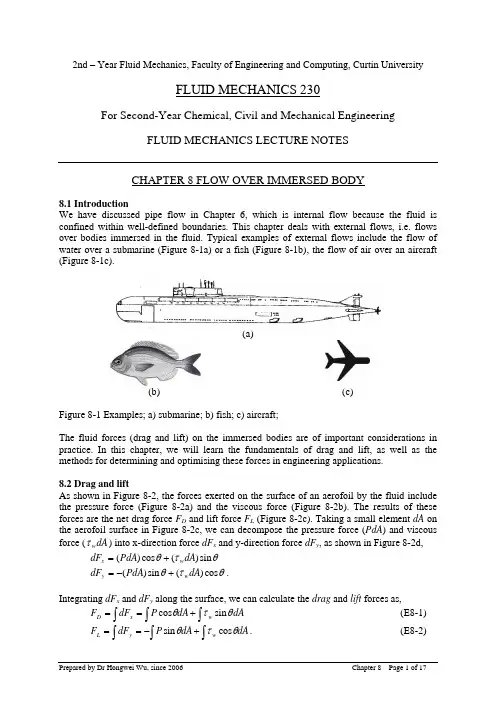
2nd – Year Fluid Mechanics, Faculty of Engineering and Computing, Curtin University FLUID MECHANICS 230For Second-Year Chemical, Civil and Mechanical EngineeringFLUID MECHANICS LECTURE NOTESCHAPTER 8 FLOW OVER IMMERSED BODY8.1 IntroductionWe have discussed pipe flow in Chapter 6, which is internal flow because the fluid is confined within well-defined boundaries. This chapter deals with external flows, i.e. flows over bodies immersed in the fluid. Typical examples of external flows include the flow of water over a submarine (Figure 8-1a) or a fish (Figure 8-1b), the flow of air over an aircraft (Figure 8-1c).(a)(b) (c)Figure 8-1 Examples; a) submarine; b) fish; c) aircraft;The fluid forces (drag and lift) on the immersed bodies are of important considerations in practice. In this chapter, we will learn the fundamentals of drag and lift, as well as the methods for determining and optimising these forces in engineering applications.8.2 Drag and liftAs shown in Figure 8-2, the forces exerted on the surface of an aerofoil by the fluid include the pressure force (Figure 8-2a) and the viscous force (Figure 8-2b). The results of these forces are the net drag force F D and lift force F L (Figure 8-2c). Taking a small element dA on the aerofoil surface in Figure 8-2c, we can decompose the pressure force (PdA ) and viscous force (dA w τ) into x-direction force dF x and y-direction force dF y , as shown in Figure 8-2d,θτθsin )(cos )(dA PdA dF w x += θτθcos )(sin )(dA PdA dF w y +−=.Integrating dF x and dF y along the surface, we can calculate the drag and lift forces as, dA dA P dF F w x D ∫∫∫+==θτθsin cos (E8-1) ∫∫∫+−==dA dA P dF F w y L θτθcos sin . (E8-2)Equations E8-1 and E8-2 reveals that 1) both shear stress and pressure contribute to the drag and lift. In the case of drag, the former is called friction drag ; the later is called pressure drag ;2) to calculate drag and lift, sufficient knowledge are required on three aspects: the body shape as it determines the distribution of θ; the distribution of pressure P and the distribution of shear stress w τ along the surface.Practically, it is very difficult to obtain the distribution of pressure and shear stress. Therefore, E8-1 and E8-2 are generally not very useful. To make it easy for engineers, dimensionless coefficients are often used instead. These dimensionless numbers are called drag coefficient C D and lift coefficient C L , defined as A V F C D D 22ρ= (E8-3) A V F C L L 22ρ= (E8-4) where A is projected (or frontal) area, i.e. the project area of the body in the flow direction.Figure 8-2 Forces on an aerofoil [1]: a) pressure force; b) viscous force; c). resultant drag andlift; d) pressure and viscous forces on a small surface area dA in (c), plotted in an x-y coordination system.8.3 The boundary layer8.3.1 Hydraulician and hydrodynamicistFor a fundamental understanding on the cause of drag and lift, we must have a good understanding on the boundary layer concept. Let’s start with some historical background on two groups of fluid mechanicians who developed two different approaches in dealing with problems of fluid mechanics by late 19th century.One is the group of hydraulicians, focused on experiments and attempted to generalise useful design equations from experimental data. This group developed the filed of experimental hydraulics, delivering empirical solutions with little theoretical content. The other is the group of hydrodynamicists, who focused on differential equations describing flows and tried to apply them to practical problems. In order to solve these differential equations, the fluid was assumed to have zero viscosity and constant density. This group developed the filed of theoretical hydrodynamics, seeking pure theoretical solutions based on ideal-fluid flows.The ideal-fluid solutions of hydrodynamicists agreed well with the observations of flows did not involve solid surface, e.g. tides, however did not agree with observed behaviours in the problems that concerned the hydraulicians, e.g, flow over immersed bodies. The following are two typical examples.(1) Flow over a thin plateFigure 8-3 illustrates the differences between the ideal solutions by the hydrodynamicists and the experimental observations by the hydraulicians for flow over a thin plate. For an ideal-fluid flow (Figure 8-3a), the fluid is inviscid, there is no friction between the fluid and the surface of the thin plate. Therefore, the fluid will maintain its free stream velocity when it flows over the thin plate. However, for a real-fluid flow, the interaction between the viscous fluid with the surface leads to a velocity gradient near the surface of the plate although the fluid far away from the plate still maintains its free stream velocity.(2) Flow over a circular cylinderFigure 8-5 shows the patterns of ideal and real flow over a circular cylinder. In absence of viscous effects, the wall shear stress is zero therefore the streamlines are symmetrical (see Figure 8-6a). The fluid coasts from the front (point A), pasts the top (point C) and then reaches to the rear (point F) of the cylinder.However, the experimental observations by the hydraulicians are very different from the above analysis by the hydrodynamicists, as shown in Figure 8-4b. A real-fluid flow cannot coast along the cylinder surface down to point F. Instead, flow separation occurs from the surface at a point between point C and F, leading to the formation of turbulent wake in the downstream (see Figure 8-4b). The friction between the viscous fluid and the cylinder surface leads to inevitable energy loss so that the flow does not have sufficient kinetic energy to travel along the surface down to the rear of the cylinder.From the above examples, it seems that the hydrodynamicists calculated what can NOT be observed while the hydraulicians observed what can NOT be calculated [2]. By early 20th century, the hydraulicians and hydrodynamicists had completely gone to live in their own worlds. The hydraulicians continued to solve their problems by trial and error based on experiments while the hydrodynamicists kept publishing academic papers based on mathematics with little bearing on engineering problems.(a) Ideal flow over a thin plate(b) Real flow over a thin plateFigure 8-3 Ideal (a) and real (b) flow over a thin plate(a) Ideal flow a cylinder (b) Real turbulent flow over a cylinderFigure 8-4 Ideal (a) and real (b) flow over a cylinder8.3.2 The boundary layer conceptThe revolutionary thinking was finally due in 1904. The two fields of theoretical hydrodynamics and experimental hydraulics were united by a German professor, Ludwig Prandtl (1857-1953). Prandtl proposed the concept of the boundary layer , which has brought the hydrodynamics and hydraulics together and laid the foundation of modern fluid mechanics.F A CTurbulentwakeThe key concept of the boundary layer is to conceptually divide the flow into two regions: •The boundary layer, the region close to solid surfaces, the effects of viscosity are too large to be ignored. Within the boundary layer, ideal-fluid flow is unsatisfactory and a set of boundary layer equations should be used.•Free stream region, the region outside the boundary layer, the effects of viscosity is small and can be neglected. In this region, Ideal-fluid flow is satisfactory.At the edge of boundary layer, the pressures and velocities of the two regions should be matched. Prandtl arbitrarily suggested the boundary layer be considered that region in which the x component of the velocity, v, is less than 0.99 times of the free-stream velocity, V, as shown in Figure 8-5.Figure 8-5 Thickness of the boundary layerThe introduction of the boundary layer concept is revolutionary in seamlessly uniting the fields of theoretical hydrodynamics and experimental hydraulics. The boundary layer concept is commonly accepted as the foundation of modern fluid mechanics, because it has •clarified numerous unexplained phenomena;•provided a much better intellectual basis for discussing complicated flows;•become a standard idea in minds of fluid mechanicians;•brought analogous ideas in heat and mass transfer, generally with useful results. However, it should be noted that•the division of the flow filed by the boundary layer concept does NOT correspond any physically obvious boundary;•the edge of boundary layer does NOT correspond to any sudden change in the flow but rather corresponds to an arbitrary definition;•even with this simplification the calculation is still difficult, and in general only approximate mathematical solutions are possible.Let’s use the boundary layer concept to explain the patterns of flow over a thin plate and flow over a circular cylinder at various Reynolds’ numbers.(1). Flow over a thin plate (Figure 8-6) [1]At a very low Reynolds number, e.g. Re = 0.1 (Figure 8-6a), the viscous force is more important than the inertial force. The viscous effects are therefore strong and the plate affects the flow considerably in a wide range (see the grey area) in all directions. Consequently, there is an extensively wide range around the plate in which the streamlines deflected considerably. The boundary layer is very thick. Outside the boundary layer is the free stream region where viscous effects are no long important so that the ideal-flow solutions is applicable.At a moderate Reynolds number, e.g. Re = 10 (Figure 8-6b), the region in which the viscous effects are important becomes much smaller. The boundary layer is much thinner. The streamlines over the plate only deflected somewhat.At a large Reynolds number, e.g. Re = 107 (Figure 8-6c), the flow is dominated by inertial force. The viscous effects are negligible anywhere except in a thin boundary layer close to the surface of the plate and the wake region. As the boundary layer is very thin, the flow streamlines are largely unaffected except slightly deflected near and within the boundary layer.Figure 8-6 Patterns of flow over a thin plate [1] at (a) a low Reynolds number; (b) a moderate Reynolds number and (c) a large Reynolds numberFigure 8-7 Patterns of flows over a circular cylinder [1] at (a) a low Reynolds number; (b) a moderate Reynolds number and (c) a large Reynolds number2). Flow over a circular cylinder (Figure 8-7) [1]At a low Reynolds number, e.g. Re = 0.1 (Figure 8-7a), flow past a cylinder is dominated by the viscous force. The viscous effects influence a large portion of the flow field, stretching to several diameters in any direction of the cylinder. However, the flow can still coast along the surface of the cylinder slowly. Such flow is sometime called creeping flow, which has streamlines essentially symmetric about the centre of the cylinder.At a moderate Reynolds number, e.g. Re = 50 (Figure 8-7b), the inertial force becomes more important. The region ahead of the cylinder in which the viscous effects are important becomes much smaller. The viscous effects are convected downstream and the flow loses its symmetry. The flow inertia dominates so that it does not coast along the surface down to the rear of the body, resulting in the formation of flow separation bubbles behind the cylinder.At a large Reynolds number, e.g. Re = 105 (Figure 8-6c), the flow is dominated by the inertialforce. The region affected by the viscous forces is forced further downstream, leading to theformation of a very thin boundary layer on the front portion of the cylinder. The boundary lay can be laminar or turbulent, depending on Reynolds number. Due to the strong inertia force, the boundary layer separation occurs from the cylinder, leading to the formation of a turbulent wake region extending far downstream. In the free stream region outside the boundary layer and the wake region, the velocity gradient is zero and the fluid flows as if it were inviscid.8.4 Drag force and streamlined bodies8.4.1 Drag forceIn 1710, Isaac Newton (cited in [2]) dropped hollow spheres from the inside of the dome of St Paul’s Cathedral in London and measured their rate of fall. He calculated that the drag force F D on a sphere and concluded that the following equation holds 242222V D V A F D ρπρ== where A is called projected (or frontal) area – the projected area seen by a person lookingtoward the object from a direction parallel to the upstream (see Figure 8-8).Figure 8-8 Drag force on a free-fall sphereIn other words, Isaac Newton thought that 122=V A F D ρ. However, subsequent experimental investigations by many other researchers found that the above formula must be modified by a coefficient C D in the right-hand side, i.e. D D C V A F =22ρ This is essentially same as the definition of drag coefficient C D in E8-3. Normally, drag coefficient C D is not 1. We can calculate the drag force of the flow on an immersed body as (E8-5)Therefore, when calculate drag force using E8-5, we have accumulated the effects of all rest factors into a single coefficient, C D , i.e. drag coefficient. One can see that the drag coefficient C D in E8-5 plays a similar role of the friction factor f in E6-22. The key difference between E8-5 and E6-22 is that in the case of pipe flow, the geometry of pipes (with different length and diameter) varies while all spheres have the same shape.8.4.2 Drag coefficient chartAccording to E8-1 and the discussion in Section 8-2, the drag coefficient of an object will be a function of Reynolds number, the shape and the surface properties of the object. We haverties)face_prope ,shape,sur Φ(C D Re = (E8-6)Practically, finding the exact function of E8-6 is extremely difficult, if not impossible. Therefore, for engineering applications, what we need is a drag coefficient chart, similar to Moody chart used for determining friction factor in pipe flows. Figure 8-9 shows the dragcoefficient as a function of Reynolds number for a smooth sphere and a smooth cylinder.Figure 8-9 Drag coefficient of a smooth sphere and a smooth circular cylinder [1].EX8-1: An exampleWe caught two breams in two consecutive casts. If we pulled the strings at the same speed, explain why we felt it was much harder to pull the big bream?Solutions:Figure 8-10The projected area of the big bream, A bf , is a much bigger than that of the small bream A sf . As both fishes are bream, we can reasonable assume that the two fishes have similar shape and surface characteristics. As both fishes were caught in consecutive casts in the same water area and we pulled the string at the same speed V , the water flows over the two fishes have same Reynolds numbers. Therefore, the drag coefficients can be taken as same. According to E8-5, the water would have induced much higher drag force on the big bream when we pulled the string.8.4.3 Pressure dragEquation E8-1 in Section 8.2 clearly shows that the drag consists of two components, friction drag and pressure drag. For flow over an immersed circular cylinder, as shown in Figure 8-7c, the fluid friction within the boundary layer certainly leads to the friction drag. In this section, let’s have a detailed analysis on the cause of pressure drag.Let’s start with inviscid flows, as shown in Figure 8-11. In absence of viscosity, the flow will coast along the cylinder surface and the streamlines are symmetrical. Based on theoretical hydrodynamics (further details can be found in Chapter 6 of Reference [1]), the distribution of pressure and velocity along the surface of the cylinder are )sin 41(21220θρ−+=V P P (E8-7) θsin 2V V fs = (E8-8) which are plotted in Figures 8-11b and 8-11c.Figure 8-11c indicates that for an ideal fluid (0=μ and ρ is constant), the fluid velocity along the surface varies from 0=fs V at the very front and rear (stagnation point A and F) of the cylinder to the maximum of V V fs 2= at the bop (point C) and bottom of the cylinder.Figure 8-11 Ideal flow over a circular cylinder [1] (a) streamlines for the ideal flow; (b) pressure distribution of the ideal flow; (c) fluid velocity distribution on the cylinder surfaceFigure 8-12 Real flow over a circular cylinder [1] (a) boundary layer separation; (b)distribution of pressure coefficient.Similarly, as shown in Figure 8-11b, the pressure distribution is also symmetrical about thevertical midplane of the cylinder, varying from a minimum of 2023V P ρ−at the top orbottom of the cylinder to a maximum of 2021V P ρ+. The decrease in pressure in thedirection of flow along the front half of the cylinder is termed as favourable pressure gradientwhile the increase in pressure in the direction of flow along the rear half of the cylinder istermed adverse pressure gradient . In absence of viscous effects, the fluid travelling from thefront to the back of the cylinder coasts down the “pressure hill” (see Figure 8-5b) from°=0θat point A to °=90θat point C and then back up to the hill to °=180θ(from point C topoint F ). Therefore, there is only energy exchange between kinetic energy and pressureenergy without any energy loss.However, the experimental observations are very different from the above theoreticalanalysis, as shown in Figure 8-12. At a large Reynolds number, the flow forms the boundarylayer on the surface of the cylinder and cannot coast along the cylinder surface down to therear stagnation point F. The boundary layer separation occurs at point D on the rear surface, (a)(b)leading to the formation of turbulent wakes in the downstream (see Figure 8-12a). The separation of the boundary layer can be explained by the pressure distribution in Figure 12b. Due to the friction between the viscous fluid and the cylinder surface, energy loss is inevitable so that after pass through point C, the fluid does not have enough kinetic energy to climb the pressure hill up to point F which sits on the top of pressure hill therefore the boundary layer separates at point D in Figure 12a.Figure 8-12b also indicates that the location of separation therefore the width of the turbulent wake and the pressure distribution on the surface depend on the nature of the boundary layer. Compared with a laminar boundary layer, a turbulent boundary layer has more kinetic energy and momentum so that it can flow further around the cylinder, resulting in a narrower wake, less drag, corresponding to a decrease in drag coefficient from point D to E in Figure 8-10. Because of the boundary layer separation, the average pressure on the front half of the cylinder is significantly greater than that on the rear half. This leads to the development of a large pressure drag. Under turbulent conditions, the friction drag is insignificant compared with the pressure drag, as discussed blow.Figure 8-13 Two objects of significant different size that have the same drag force [1]: (a) a circular cylinder - a blunt body, C D = 1.2; (b) a streamlined strut C D = 0.12.Table 8-1 Drag coefficients of various bodies8.4.4 Streamlined bodiesIt is clear now that the drag force developed on an object immersed in turbulent fluid isdominantly pressure drag as a result of boundary layer separation. Therefore, we can optimisethe body shape of the object to minimise the boundary layer separation hence reduce pressuredrag. This requires us to design streamlined bodies .Figure 8-13 shows the significance of body streamlining. The streamlined strut has a sizemuch bigger than the circular cylinder. However, the two bodies have the same drag forces.The boundary layer separation on the streamlined strut has been postponed to the tail of thebody so that pressure drag is minimised compared with that on a circular cylinder, which is ablunt body. It is interesting to revisit the shapes of submarine, fish and aerofoil in Figures 8-1and 8-2, we would appreciate that these bodies are actually all streamlined.8.4.5 Drag coefficient for various objectsThe drag coefficient information for a wide range of objects is available in the literature [1,2].Some of this information is listed in Table 8-1.8.4.6 Drag coefficient at low Reynolds number (Re < 1)At Re < 1, the flow over an immersed body is called creeping flow , dominated by viscouseffects. The drag coefficient gives the 1/Re dependence. Table 8-2 shows the drag coefficientsfor various bodies at Re < 1.Table 8-2 Drag coefficient of various bodies at Re < 1, from Reference [1]8.6 Terminal velocityIf an object in a body of fluid is free to move subject only to gravity, or perhaps centrifugalforces in certain circumstances, then it accelerates to a particular velocity at which the tractiondeveloped and the other forces on the body balance. This velocity is called terminal velocity .Generally, the acceleration is very rapid so that the whole process can be treated as the objecttravelling at the terminal velocity.Figure 8-14a illustrates the concept of terminal velocity of a sphere settling in a fluid. Figure8-14b shows the force analysis of the sphere. When the sphere travels at the terminal velocityV t , the force is balanced. V V V V Re4.20Re6.13Re0.24Re2.22Therefore, as shown in Figure 8-14b, the gravity force F W , drag force F D and buoyancy forceF B are in balance,B D W F F F += (E8-9)We know thatobject object W gV F ρ= (E8-10)object fluid B gV F ρ= (E8-11) projected t fluid D D A V C F 22ρ= (E8-12) where6)2(3433D D V object ππ== (E8-13)42D A projected π=. (E8-14)Assuming Re < 1, for a sphere (see Table 8-2), the drag coefficient is DV C t fluid fluid D ρμ24Re 24==. (E8-15)Substituting E8-15 into E8-12, we have t fluid t fluid t fluid fluid projected t fluid D D DV D V D V A V C F πμπρρμρ342242222===. (E8-16)This is the famous Stock’s law, which is only valid when Re < 1.(a) Concept of terminal velocity (b) Force analysisFigure 8-14 Terminal velocity of a sphereSubstituting E8-11, E8-13 and E8-16 into E8-9, we have fluidfluid object t gD V μρρ18)(2−= (E8-17)Equation E8-17 is not generally given for calculations so that if not available we are requiredto go through the force analysis for its derivation.Once we have calculated the terminal velocity, one final critical step is to double check Re toensure that 0.1Re <=fluid t fluid D V μρ (E8-18)so that our assumption leading to E8-16 is indeed valid.Solutions:We can use a free-body diagram of a mineral particle, as shown in Figure 8-14b. The mineralparticle moves downward with a constant velocity V t (relative to the moving air flow)that isgoverned by a balance between weight of particle, F W , the buoyancy force of the surroundingair, F B , and the drag of air on the particle, F D . Please Note: it is acceptable that thebuoyancy force of the surrounding air, F B , is neglected.(a) We haveB D W F F F += (E8-19)63p p p p W D g gV F πρρ== (E8-20) 63p air p air B D g gV F πρρ== (E8-21)Assuming Re <1, we have the drag coefficient of an mineral particle pt air air D D V C ρμ24Re 24== (E8-22) Therefore the drag force p t air pt air air p t air D p t air D D V D V D V C D V F πμρμπρπρ3244214212222=== (E8-23) Substitute E8-20, E8-21 and E8-23 into E8-19, we have p air p air p p UD D g D g πμπρπρ36633+= Therefore, the terminal velocity of a mineral particle relative to the flowing air is air p air p t gD V μρρ18)(2−= or airp p t gD V μρ182= if buoyancy is neglected,Therefore, we haves m m Ns m s m m kg m kg gD V air p air p t /029.0)/1079.1(18)1020(/8.9)/29.1/2400(18)(25262332=×××××−=−=−−μρρCheck Reynolds number 0.10418.0/1079.11020/029.0/29.1Re 2563<<=××××==−−m Ns m s m m kg D V air p t air μρ Therefore, the assumption to use E8-22 is valid.(b) We can calculate the air travelling velocity in the vertical tube s m m s L m L D Q A Q V tube air /017.0)05.0(14.3)60min 110001min 0.2(44232=××××===π Therefore, the residence time of a mineral particle in the vertical tube is 3.16/)017.0029.0(75.0=+=+=sm m V V L t air t sReferences[1]. Munson BR, Young DF and Okiishi TH, Fundamentals of Fluid Mechanics, 4th Edition,John Wiley & Sons, Brisbane, 2002.[2]. Noel de Nevers, Fluid Mechanics for Chemical Engineers, 3rd Edition, McGraw-Hill’sChemical Engineering Series, Sydney 2005.。
Computational Fluid Dynamics Computational Fluid Dynamics (CFD) is a branch of fluid mechanics that uses numerical analysis and algorithms to solve and analyze problems that involve fluid flows. It has become an essential tool in various industries, including aerospace, automotive, and environmental engineering, due to its ability to simulate and predict the behavior of fluids in complex systems. This technology has revolutionized the way engineers and scientists approach fluid dynamics problems, offering a cost-effective and efficient alternative to traditional experimental methods. The development of Computational Fluid Dynamics can be traced back to the early 20th century when scientists began to explore the mathematical modeling of fluid flows. However, it was not until the advent of digital computers in the 1960s that CFD began to gain traction as a practical tool for engineering applications. The ability to solve complex equations governing fluid flows numerically allowed engineers to tackle problems that were previously deemed intractable, leading to significant advancements in the design and analysis of various systems. From a historical perspective, the evolution of CFD has been marked by significant milestones, including the development of finite difference and finite element methods, as well as the introduction of commercial CFD software packages in the 1980s. These advancements have democratized the use of CFD, making it accessible to a wide range of industries and applications. Today, CFD is an indispensable tool for engineers and scientists, offering insights into fluid behavior that would be impossible to obtain through experimental means alone. One of the key debates surrounding Computational Fluid Dynamics revolves around the trade-off between accuracy and computational cost. While CFD has the potential to provide highly detailed and accurate simulations of fluid flows, the computational resources required to achieve such precision can be prohibitive. This has led to ongoing discussions about the balance between accuracy and efficiency in CFD simulations, with researchers exploring techniques to optimize computational performance without compromising the fidelity of the results. To illustrate the impact of CFD, consider the example of aerodynamic simulations in the automotive industry. By using CFD to analyze the airflow around vehicles, engineers can optimize the design of car bodies and components to reduce drag, improve fuelefficiency, and enhance stability. This has led to significant advancements in automotive aerodynamics, resulting in vehicles that are more fuel-efficient and environmentally friendly. Similarly, in the aerospace industry, CFD has been instrumental in the design of aircraft, enabling engineers to optimize wing shapes, engine placements, and control surfaces to improve performance and safety.Despite its numerous benefits, Computational Fluid Dynamics also has its limitations. One of the primary challenges is the validation of CFD simulations against experimental data, particularly in complex flow regimes where turbulence and other nonlinear phenomena are prevalent. While CFD has the potential toprovide valuable insights into fluid behavior, the accuracy of the simulations is contingent on the fidelity of the underlying mathematical models and the qualityof the numerical discretization. As such, there is a need for ongoing research to improve the robustness and accuracy of CFD methods, particularly in challenging flow scenarios. Looking ahead, the future of Computational Fluid Dynamics holds significant promise, with ongoing advancements in computational hardware and software paving the way for more sophisticated and accurate simulations. The integration of machine learning and artificial intelligence techniques into CFD workflows is also poised to revolutionize the field, offering new avenues for optimizing simulations and gaining insights into complex fluid dynamics phenomena. Additionally, the continued collaboration between academia, industry, and government institutions will be crucial in driving the development and adoption of CFD for a wide range of applications. In conclusion, Computational Fluid Dynamics has emerged as a powerful and versatile tool for simulating and analyzing fluid flows in various engineering and scientific disciplines. Its historical development, from the early theoretical foundations to the widespread use of commercial software packages, underscores its significance in modern engineering practice. While CFD offers numerous benefits, including the ability to optimize designs, improve performance, and reduce costs, it also presents challengesrelated to computational cost and validation. Looking ahead, the futureimplications of CFD are promising, with ongoing advancements in hardware, software, and methodology poised to further enhance its capabilities and impact. As thefield of CFD continues to evolve, it is essential for researchers andpractitioners to remain vigilant in addressing its limitations and harnessing its potential to drive innovation and progress in engineering and scientific endeavors.。
飞机维修中各类工具中英文对照扳手Wrenches/套筒Sockets开口扳手Open End Wrenches梅花扳手Spline End Wrenches块扳手Crowfoot Wrenches开口/梅花扳手Combination Wrenches内六角扳手Hex Wrenches平板棘轮扳手Slab Ratchet棘轮扳手Ratchet Wrenches力矩扳手Torque Wrenches管钳Pipe Wrenches活动扳手Adjustable Wrenches六角套筒Six Point Sockets梅花套筒Twelve Point Sockets万向套筒Universal Sockets转接头Adaptor套筒接杆Socket Extension万向转接头Universal Joint螺刀Screwdrivers快速螺刀Fast Screwdrivers仪表螺刀Electronic miniature Screwdrivers 十字头螺刀PILLIPS Screwdrivers磁性螺刀Magnetic Screwdrivers一字头螺刀Flat Tip Screwdrivers摇把Speeders钳Pliers尖嘴钳Needle Nose Pliers大力钳Locking Pliers保险丝钳Safety Wire Twisters鹰嘴钳Adjustable Joint Pliers插头钳Connector Plug剥线钳Wire Strippers鱼口钳Combination Slip-Joint Pliers卡环钳Convertible Snap Ring Pliers剪线钳Diagonal Cutters压线钳Wire Crimpers电气工具Electronic Tools矿灯Safety Lamb(Miner’s Lamb)手电Flashing Light对讲机Interphone电烙铁Electronic Iron耳机Earphone防静电手腕Static Wrist电池Battery充电器Charger扬声器Speaker电源插座Receptacle电枪Electronic Runner电钻Electronic Drills指挥棒Flashing Emergency Light超声波Ultrasonic测量工具Measuring Tools钢板尺Steel Rulers卷尺Tape Rulers螺旋卡尺Outside Micrometer塞尺Feeler(Thickness)Gauges量杯Measuring Cup游标卡尺Dial Caliper表Gauges三用表Multi Meter兆欧表Meg Ohm Meter杂项Diversiform反光镜Inspection Mirror放大镜Magnifier软杆双爪式机械手Flexible Two_claw Pick Up Tool软杆磁棒Flexible Magnetic Pick Up Tool 划刀Utility Knife刮刀Scraper Knife剪刀Snip(Scissor)锯Saw凿子Chisels錾子Punch三脚架Tripod(Spider)铜榔头Copper Hammer铁榔头Iron Hammer胶榔头Rubber Hammer弯勾Hook锉File镊子Nipper(Pliers)销钉插拔工具Pin Removal Tools气枪Pneumatic Runner气钻Pneumatic Drills铆钉枪Rivet Gun注射器Injector(Squirt)滑油加油车Oil Cart液压油加油车Hydraulic Fluid Cart注油枪Grease Gun抹布Dishcloth手套Glove绳索Rope工具箱Tools Kit工具架Tools Rack千斤顶Jack撬棒Tommy Bar工作梯Work Ladder砂轮Grinding wheel砂纸Sand paper胶带Adhesive Tape焊锡Soldering Tin拖把Tow Bar发光背心Flashing Vest护目镜Goggle(Blinkers)安全带Life Belt(Safety Belt)增补两用扳手CONBINATION SPANNER两用扳手套装COMBINATION SPANNER SET加长型两用扳手COMBINATION SPANNER EXTRA LONG梅花棘轮开口扳手OPEN ENDED SPANNER WITH RING RATCHET 梅花棘轮开口扳手套装OPEN ENDED SPANNER WITH RING RATCHET SET两用棘轮扳手COMBINATION RATCHET SPANNER两用棘轮扳手套装COMBINATION RATCHET SPANNER SET1/4'连接物ADAPTOR1/4'组合支架工具COMBINATION HOLDING TOOL小型发光二极管MINIATURE LED LAMP活动扳手SINGLE OPEN ENDED SPANNER扳手套装MAGNETO SPANNER SET单开口扳手/呆扳手SINGLE ENDED OPEN JAW SPANNER双开口扳手DOUBLE OPEN ENDED SPANNER双开口扳手套装DOUBLE OPEN ENDED SPANNER SET扩口螺母扳手PLARE NUT SPANNER(OPEN)半月型梅花扳手HALF-MOON RING SPANNER双头梅花扳手(短)DOUBLE ENDED SPANNER(SHORT)双头梅花扳手(长)DOUBLE ENDED SPANNER(LONG)平头梅花扳手(直)FLAT RING SPANNER STRAIGHT PATTERN 开口敲击扳手OPEN ENDED SLOGGING SPANNER梅花敲击扳手RING SLOGGING SPANNER高颈梅花敲击扳手DEEP AFFSET RING SLOGGING SPANNER直头梅花扳手DEEP RING SPANNER(STRAIGHT PATTERN)延长管EXTENSION TUBE爪型扳手CROWFOOT SPANNER两用活头扳手COMBINATION SWIVEL HEAD WRENCH活结T型扳手SWIVEL HANDLE WITH SLIDING T套筒扳手SOCKET WRENCH弯头套筒扳手ANGLED SOCKET WRENCH双头套筒扳手DOUBLE ENDED SOCKET WRENCH旋棒TOMMY BAR分节旋棒STEPPED TOMMY BAR3C把手套筒扳手SOCKET WRENCH WITH3C-HANDLET型及磁性套筒扳手SOCKET WRENCH WITH T-HANDLE AND MAGNET 钩头扳手HOCK SPANNER WITH LUG带销扳手PIN SPANNER可调式两爪钩扳手CALIPER FACE SPANNER WITH ADJUSTABLE1/4'标准六角套筒HEXAGON SOCKET1/4'加长六角套筒HEXAGON LONG PATTERN SOCKET棘轮扳手RATCHETS套筒SOCKETS套筒套装SOCKETS SETS摩擦棘轮扳手FRICTION RATCHETS冲击工具IMPACT TOOLS旋具头BITS扭矩扳手TORQUE WRENCHES1/4梅花套筒SOCKET UD PROFILE1/4六角套筒星型套筒SOCKET FOR PROTRUDING HEAD SCREWS1/4一字,十字,星型,内六角旋具套筒1/4’双向棘轮套筒扳手1/4’REVERSIBLE RATCHETT柄棘轮扳手RATCHET WITH T-HANDLE手用棘轮头HAND RATCHET WITHOUT HANDLE1/4转3/8转换接头CONVERTER1/4TO3/8T型滑动头手柄TOMMY BAR WITH SLIDING T活动延长杆FLEXIBLE EXTENSION通用延长杆UNIVERSAL-JOINT EXTENSION1/4四方驱动连接头SQUARE-DRIVE COUPLER1/4万向接头UNIVERSAL JOINT活动头手柄SWIVEL HANDLE套筒固定夹SOCKET RAIL WITH MAGNETIC3/8一字,十字,星型,内六角旋具套筒3/8六角套筒SOCKET HEXAGON3/83/8梅花套筒SOCKET UD PROFILE塑料棘轮扳手PLASTIC RATCHET旋具头接头BIT ADAPTOR旋具头棘轮扳手BIT RATCHET旋具头螺丝起子BIT SCREWDRIVER旋具头延长杆BIT EXTENSION旋具头SCREWDRIVER BITS风动套筒IMPACT SOCKET风动套筒附件ACCESSORIES FOR IMPACT SOCKET手动操作冲击手柄HAND-OPERATED INPACT DRIVER摩擦式梅花棘轮扳手FRICTION TYPE RATCHET WITH RING WITH BI-HEXAGON摩擦式四方棘轮扳手FRICTION TYPE RATCHET WITH SQUARE RING 安装扳手/尖尾扳手CONSTRUCTION RATCHET BI-HEXAGON0.6-5.4NM扭力螺丝起子TORQUE SCREWDRIVER HANDLE0.6-5.4NM3C一字螺丝起子3C-SCREWDRIVER FOR SLOTTED HEAD SCREWS3C十字PH螺丝起子3C-SCREWDRIVER FOR CRUCIFORM HEAD PH3C米字螺丝起子3C星型螺丝起子3C球头六角螺丝起子5件/6件/7件/155件螺丝起子套装SET FOR HEAD SCREWS电工螺丝旗子ELECTRONIC SCREWDRIVER木柄螺丝起子SCREWDRIVERS WITH WOODEN HANDLE磁化/消磁器MAGNETIZER AND DEMAGNETIZER方刃锥子SQUARE BLADED AWLT型六角螺丝起子HEXAGON SCREWDRIVER WITH T-HANDLET型内六角扳手HEXAGON SOCKET KEY WITH T-HANDLE内六角扳手HEXAGON SOCKET KEY加长内六角扳手EXTRA LONG HEXAGON SOCKET KEY加长球头内六角扳手内六角扳手套装HEXAGON SOCKET KEY SETT型星形螺丝起子SCREWDRIVER WITH T-HANDLE曲柄螺丝起子CRANKED SCREWDRIVER量规GARGE车灯测电笔CAR LIGHT TESTER6-24伏测电笔VOLTAGE TESTER6-24V150-250伏测电笔VOLTAGE TESTER150-250V钳子3件套装PLIERS SET,3-PIECE万能手钳48件套UNIVERSAL PLIERS ASSORTMENT WITH48PIECE 小钢丝钳SMALL COMBINATION PLIERS钢丝钳(德式)COMBINATION PLIERS(GERMAN PATTERN)钢丝钳(欧式)COMBINATION PLIERS(EURO PATTERN)强力钢丝钳POWER COMBINATION PLIERS塑料水口钳SIDE CUTTERS FOR PLACTIC剪钳(瑞典款式)SIDE CUTTERS(SWEDISH PATTERN)电工剪钳ELECTRICIAN’S SIDE CUTTERS剪钳(美国款式)POWER SIDE CUTTERS(AMERICAN PATTERN)杠杆剪钳LEVER-ACTION SIDE CUTTERS杠杆顶剪钳LEVER-ACTION END CUTTING NIPPERS核头钳TOWER PINCERS拨钉钳PINCERS平头钳FLAT NOSE PLIERS圆头钳ROUND NOSE PLIERS直头尖嘴钳LONG NOSE PLIERS弯头尖嘴钳电话钳TELEPHONE PLIERS强力尖嘴钳TRIPLE-FUNCTION PLIERS直口机修工钳MECHANICS PLIERS STRAIGHT PATTERN曲口机修工钳MECHANICS PLIER ANGLED PATTERN偏口机修工钳MECHANICS PLIER OFFSET PATTERN30度平圆机修钳MECHANICS PLIER WITH30电缆刀CABLE KNIFE电工电缆刀ELECTRICIAN’S CABLE KNIFE防静电专用钳子电子钳ELECTRONIC PLIERS迷你电子钳MINIATURE ELECTRONIC PLIERS防静电尖嘴钳/防静电顶切钳/电子平头钳/电子剪钳/防静电剪钳/电子剥线钳电缆剪钳CABLE CUTTERS小型万用剪SMALL UNIVERSAL SCISSORS万用电缆刀UNIVERSAL CABLE KNIFE自动剥线钳STRIPPING PLIERS ANTOMATIC剥线钳STRIPPING PLIERS固定剥线钳STRIP-FIX STRIPPING PLIERS剥线工具WIRE STRIPPER高效剥线钳HIGH-PERFORMANCE WIRE STRIPPER数据传输电缆精确剥线钳PRECISION WIRE STRIPPER FOR DATA CABLES同轴电缆剥线钳WIRE STRIPPER FOR COAXIAL CABLES绝缘剥漆钳INSULATING VARNISH STRIPPER剥线刀WIRE STRIPPING KNIFE绝缘胶带INSULATING TAPE压线钳CRIMPING PLIERS锁把式压线钳LOCK-GRIP CRIMPING PLIERS端子压线钳WIRE END-SLEEVE PLIERS模块压线夹钳MODULAR LOCK-GRIP CRIMPING PLIERS模块压线钳MODULAR CRIMPING PLIERS精确压线钳PRECISION CRIMPING PLIERS外卡簧钳(轴用)EXTERNAL CIRCLIP PLIERS(ON SHAFTS)直头/弯头外卡簧钳(轴用)内卡簧钳(孔用)INTERNAL CIRCLIP PLIERS(IN BORES)直头/弯头内卡簧钳(孔用)大型/重型卡簧钳X型把X-GRIP大力钳LOCK-GRIP PLIERS平行钳夹大力钳PARALLEL JAW LOCK-GRIP PLIERS宽口大力钳WIDE JAW LOCKING PLIERS滑行杆式大力钳LOCK-GRIP SLIDE CLAMP固定大力钳GRIP WRENCH FOR GLUEING机械工作台钳MACHINE WORKBENCH CLAMP焊接大力钳LOCK-GRIP WELDING CLAMP管子焊接大力钳LOCK-GRIP TUBE WELDING CLAMPC型大力钳LOCK-GRIP C CLAMP水泵钳UNIVERSAL PLIERS(7种设置/5种设置)水泵钳WATER PUMP PLIERS特殊水泵钳SPECIAL WATER PUMP PLIERS可调式高速管子钳HIGH-SPEED PIPE WRENCH WITH SCREW ADJUSTER 高速曲口管子钳HIGH-SPEED PIPE WRENCH CURVED迷你链式管子钳MINI CHAIN PIPE WRENCH链钳CHANIN PIPE WRENCH重型管子钳STILLSON PIPE WRENCH断线钳BOLT CUTTERS钳子套装(3件/4件/6件/8件)VDE绝缘安全电工工具VDE INSULATED SAFETY TOOLSVDE绝缘标准符合DIN EN60900IEC60900:2004以及VDE680适合在高压区安全工作(AC1000V DC1500V)VDE绝缘螺丝起子VDE SCREWDRIVER(一字/十字/米字/星型/内六角)VDE绝缘起子套装电压传感器/电压测试器VOLTAGE DETECTOR/TESTER绝缘扭力扳手VDE TORQUE WRENCH绝缘双向棘轮扳手VDE REVERSIBLE RATCHET绝缘六角套筒VDE SOCKET HEXAGONAL绝缘旋具头套筒VDE SCREWDRIVER BIT SLCKETT型绝缘扳手VDE T-HANDLE绝缘延长杆VDE EXTENSION绝缘电工工具组套(3件/8件/14件/108件)VED3C绝缘手柄套筒扳手VDE SOCKET WRENCH WITH3C HANDLE绝缘梅花扳手VDE SINGLE-ENDED RING SPANNER WITH DEEP OFFSET 绝缘开口扳手VDE SINGLE-ENDED OPEN SPANNERVDE绝缘钢锯HACKSAW绝缘电缆刀VDE CABLE KNIFE绝缘电缆剪CABLE SHEARS棘轮式绝缘电缆剪钳CABLE CUTTERSVDE绝缘电缆剪VDE CABLE SHEARS绝缘剥线钳/绝缘固定剥线钳/绝缘水泵钳/绝缘强力钢丝钳/绝缘斜口钳/绝缘电工斜口钳/绝缘平口钳/绝缘圆头钳/绝缘直头尖嘴钳/绝缘弯头尖嘴钳VDE绝缘橡胶垫VDE RUBBER COVER SHEETVDE绝缘电工安全手套VDE ELECTRICIANS’S SAFETY GLOVES绝缘塑料夹VDE PLASTIC CLAMPS车轮扳手WHEEL WRENCHES十字扳手4WAY WHEEL WRENCH撬棒TYRE LEVER轮毂罩移除工具HUBCAP RENOVING TOOS配重钳BALANCE-WEINHT PLIERS制动弹簧钳BRAKE-SPRING PLIERS闸线弹簧钳PLIERS FOR BRAKE-CABLE SPRINGS制动钳刷BRAKE-CALIPER BRUSH放油塞扳手(四方)DRAIN-PLUG WRENCH WITH SQUARE 油壶OIL CANS过滤器扳手UNIVERSAL FILTER WRENCH皮带钳PULLEY WRENCH阀门研磨机VALVE GRUNDER阀门研磨工具VALVE LAPPING TOOS油封钳VALVE-SEAL PLIERS GUNMETAL FINISH汽缸/活塞环压缩器VALVE SPRING COMPRESSOR BRIGHT NICKEL-PLATDE 活塞环钳PISTON RING PLIERS软管夹钳HOSE CLIP PLIERS电极拉马BATTERY TERMINAL PULLER电池测试器BATTERY TESTER火花塞套筒SPARK PLUG SOCKET火花塞套筒扳手SPARK PLUG SOCKET WRENCH火花塞刷SPARK-PLUG BRUSH特殊尖冲凿SPECIAL PIN PUNCH弹簧撑开器SPRING SPREADER球头拉拔器UNIVERSAL BALL JOINT REMOVER通用罐UMIVERSAL CANISTER防冻测试器ANTI-FREEZE TESTER安装钳INSTALLATION PLIERS吸盘SUCTION LIFTER磁性拾取工具MAGNETIC PICK-UP TOOL金属片切割器NIBBER杠杆剪切机LEVER-ACTION TIN SNIPS打孔钳PUNCH PLIERS橡胶锤RUBBER HAMMER塑料锤PLASTIC HAMMER无后坐力锤RECOILLESS HAMMER钳工球头锤ENGINEERS’S BALL PEIN HAMMER钳工锤ENGINEERS’S HAMMER平面刮刀FLAT SCRAPER三角空心刮刀THREE-EDGED HOLLOW-GROUND SCRAPER三角实心刮刀THREE-EDGED FLAT-GROUND SCRAPER密封刮刀GASKET SCRAPER平锉HAND FILE圆锉ROUND FILE三角锉TRIANGULAR FILE半圆锉HALF-ROUND FILE锉类6件套装中心冲/凿/开口销冲CENTRE PUNCHES/CHISELS/DRIFT PUNCHES 钢锯HACKSAW栓孔锯KEYHOLE SAW小金属锯SMALL METAL SAW小PUK钢锯PUK JUNIOR HACKSAWHOBBY锯台钳/台虎钳METALWORKING VICE(100/125/150mm)钢卷尺STEEL TAPE MEASURE(3米/5米/8米)阀塞尺VALVE FEELER GAUGE塞尺火花塞塞尺SPARK PLUG GAUGE螺纹规THREAD GAUGE游标卡尺POCKET VERNIER CALLIPER数显游标卡尺DIGITAL CALLIPER划线器SCRIBER镊子TWEEZERS十字镊子CROSSLOCK TWEEZERS螺钉取出器BOLT EXTRACTOR断螺钉取出器套装SCREW EXTRACTOR SET机械螺母破开器MECHANICAL NUT SPLITTER螺栓插入及取出器STUD INSERTER AND EXTRACTOR丝锥THREAD FILE管子割刀PIPE CUTTER自动切割机AUTOMATIC PIPE CUTTER链式切管机CHAIN PIPE CUTTER虹吸扳手SIPHON TRAP PLIERS钢丝刷WIRE BRUSH锉刀清洁刷FILE CLEANING BRUSH裁缝剪TAILORS SCISSORS发光二极管井下检查灯LED INSPECTION LAMP井下检查灯INSPECTION LAMP发光二极管工作灯LED WORK LIGHT工程锤ENGINEERS HAMMER ROTBAND-PLUS工程圆头锤ENGINEERS’BALL PEIN HAMMER胡桃木备用手柄SPARE HANDLE HICKORY工匠锤JOINERS’HAMMER ROTBAND-PLUS石匠锤CLUB HAMMER双面石匠锤DOUBLE FACED CLUB HAMMER ROTBAND-PLUS大锤SLEDGE HAMMER大碎石锤STONE SLEDGE HAMMER劈木锤WOOD SPLITTING HAMMER铺路锤PAVING HAMMER单板锤VENEER HAMMER磁性锤MAGNETIC HAMMER ROTBAND玻璃装配工锤GLAZIERS HAMMER炭化合金瓦锤CARBIDE TILE HAMMER羊角锤CLAW HAMMER电焊敲锤SCALING HAMMER ROTBAND-PLUS无弹力安全锤RECOILLESS HAMMER安全锤SAFETY HAMMER SOFT-PLUS塑料锤PLASTIC HAMMER橡皮锤RUBBER MALLET HARD尼龙锤NYLON HAMMER木锤WOOLEN MALLET铜锤COPPER HAMMER CLUB SHAPE铝锤ALUMINIUM HAMMER ROTBAND桶形铝锤LEAD HAMMER SARREL SHAPE冷凿锤COLD CHISEL HAMMER热凿锤HOT CHISEL HAMMER平底压摸锤SET HAMMER TOP PART压槽铁锤TOP FULLER上型模锤BOTTOM FULLER冲锤PUNCH HAMMER镰刀锤SCYTHE HAMMER锻工钳BLACKSMITH’S TONGS铆钉钳RIVETTING TONGS锥型冲子/中心冲子/销式冲子DRIFT PUNCHES/CENTRE PUNCHES/PIN PUNCHES 自动中心冲子AUTOMATIC CENTRE PUNCH WITH TIP 冲子组套DRIFT PUNCH SET铆钉装配器RIVET SETTER字母及数字冲子LETTER AND NUMBER PUNCHES装配冲子SETTING PUNCH撬杆PRVBAR起钉器NAIL FIFER OCTAGONAL撬棍CROWBAR通用拉马UNIVERSAL PULLER两爪拉马PULLER2-ARM PATTERN三爪拉马PULLER3-ARM PATTERN防腐蚀拉马COROSTOP PULLER PATTERN快速拉马QUICK-ACTION PULLER两爪液压拉马UNIVERSAL2-ARM PULLER拉马延长杆EXTENSION FOR PULLERS液压轴杆HYDRAULIC PRESSURE SPINDLE三爪液压拉马UNIVERSAL2-ARM PULLER拉马套装PULLER SET螺母劈开器NUT SPLITTER液压螺母劈开器NUT SPLITTER HYDRAULIC螺栓提取器STUD EXTRACTOR轴承提取器BALL BEARING EXTRACTOR滚珠轴承提取器套装BALL BEARING EXTRACTOR SET内提取器INTERNAL EXTRACTOR冲击轴承拉马IMPACT BEARING PULLER汽缸拉马CYLINDER LINER PULLER COMPLETE WITH SUPPORT BRACE 分离拉马SEPARATOR PULLER轴承分离器BEARING SEPARATOR传动轴轴承拉马DRIVE SHAFT BEARING PULLER分离器及拉马套装SEPARATOR AND PULLER SET拉拔卡盘PULLING CHUCK液压泵HYDRAULIC PUMP液压手泵HYDRAULIC HAND PUMP液压工具拉马1.50PULLER FOR HUDRAULIC IMPLEMENT1.50液压增力器HYDRAULIC PRESS轮毂拉马WHEEL-HUB PULLER传动轴拉马DRIVE-SHAFT PULLER方向盘拉马STEERING-WHEEL PULLER装配叉DISMANTLING AND ASSEMBLY FORK球头拉拔器BALL JOINT PULLER三爪机滤扳手OIL FILTER HOOK弹簧撑SPRING SPREADER塑料轴承安装套装PROFESSINAL PLASTIC BEARING INSTALLATION SET 法兰分离器FLANGE SEPARATORS轨距测量器TRACK ALIGNMENT GAUGE扳手WRENCHES管子切割器PIPE CUTTERS扩口工具FLARING TOOLS弯管机PIPE BENDERS管子工具PLUMBING TOOLS铁皮剪/断线钳TIN SNIPS/BOLT CUTTERS管子清洁设备PIPE CLEANING EQUIPMENT弯管系统PIPE BENDING SYSTEMSSNAP管道扳手PIPE WRENCH ECK-SNAP钢管切割器PIPE CUTTER TUBEX FOR STEEL PIPES生铁管切割器PIPE CUTTER TUBEX FOR CAST IRON PIPES不锈钢管切割器RATCHET PIPE CUTTER NIRO FOR STAINLESS STEEL PIPES管子修边器PIPE DEBURRING REAMER不锈钢管修边器PIPE DEBURRING REAMER FOR STAINLESS STEEL PIPES 扩口工具套装FLARING TOOL SET BOERDEX钢管扩口钳EXPANDER PLIERS FOR COPPER PIPES带滑轨的弯管机PIPE BENDER WITH SLIDE RAIL带滚轴的弯管机PIPE BENDER WITH ROLLER弯管钳PIPE BENDING PLIERS带滑轨的弯管钳PIPE BENDING PLIERS WITH SLIDE RAIL 带滚轴的弯管钳PIPE BENDING PLIERS WITH ROLLER手动弯管机MANUAL BENDING TOOL液压弯管机HYDRAULIC PIPE BENDER手动液压弯管机PIPE BENDING MACHINE FOR MANUAL HYDRAULIC OPERATION 电动液压弯管机PIPE BENDING MACHINE FOR ELECTRO HYDRAULIC OPERATION 管道矫直工具PIPE STRAIGHTENING TOOL金属片弯边钳SHEET METAL CRINPING PLIERS折边钳SEAMING PLIERS快速夹取扳手QUICK-CLAMP WRENCH夹管钳GRIPPING PLIERS分级扳手STEPPED KEY复合分级扳手COMBINATION STEPPED KEY铁皮剪TIN SNIPS/HOLE CUTTING SNIPS/PELICAN PATTERN SNIPS 断线钳BOLT CUTTER管道清洁软轴FLEXIBLE PIPE CLEANING SHAFT排水管清洁器DRAIN PIPE CLEANER工作台几工作桌WORKBENCHES AND WORK TABLES工具车TOOL TROLLEYS工具柜TOOL CABINETS车间推车WORKSHOP TROLLEYS抽屉柜/箱DRAWER-CABINETS/BOXES衣柜/工作服柜WARDROBES矮橱LOWER CUPBOARD UNIT图纸夹DRAWING HOLDER电源面板PWER SUPPLY PANEL防酸放腐蚀工作台面板六边形工作台HEXAGONAL WORKBENCH带抽屉工作台WORKBENCH WITH DRAWER CABINET塑料抽屉插件PLASTIC DRAWER INSERT工作桌推车WORKSHOP TABLE TROLIEYS工作台WORKBENCH带背板工作台坚固推车TROUGH TROLLEY平板车PLATFORM TROLLEY带手柄平板车PLATFORM TROLLYE WITH HANDLE维护推车SERVICE TROLLEY带工具箱车间推车WORKSHOP TROLLEY WITH TOOL CHEST工具箱TOOL CHEST存放斗STORAGE TRAY卷纸架PAPER ROLL HOLDER垃圾桶WASTE BASKET移动架写字板LECTERN WORKTOP存储盒STORAGE BOXES带门库架CUPBOARD WITH SHELVING WITH DOORS开敞式壁板COMPLETE PANEL SYSTEM WITH SLOTTED PANELS 存物柜LOCKER WITH HINGED DOORS滑门橱CUPBOARD WITH SLIDING DOORS电脑柜COMPUTER CABINET桌上设备DESK INSTALLATION移动电脑架PC STAION MOBILE电脑车间组合PC WORKPLACE COMBINATION更衣室条凳CHANGING CUBICLE SEAT BENCH安全橱SAFETY CUPBOARD衣橱CLOTHES LOCKER带凳子的衣橱CLOTHES LOCKER WITH SEAT BENCH消防员衣橱FIREFIGHTER’S CUPBOARD工具橱TOOL CABINET移动式可回收物品垃圾收集箱RECYCLING WASTE-COLLECTION CONTAINER MOBILE固定可回收物品垃圾收集箱RECYCLING WASTE-COLLECTION CONTAINER STATIONARY 分类垃圾收集站WASTE-COLLECTION STATION CONTAINER立式烟灰缸STAND ASHTRAYOCHSENKOPF系列斧头欧洲ILTIS型斧制图用刮刀专业伐木斧快劈斧抢险袖珍刀CAROLUS特殊工具KLANN汽车专用工具弹簧压缩器横杆球头拉拔器轮轴拉马液压手用压力器轴衬提取器发动机锁定工具套装扭距测试仪及设备TORQUE TESTER AND EQUIPMENT扭距倍增器TORQUE MULTIPLIERS扭距角度指示器TORQUE ANGLE INDICATORS特殊DREMO工具SPECIAL DREMO TOOLSDREMOMETER系列扭力工具DREMOMETER TOOLS扭距螺丝刀TORQUE SCREWDRIVERS扭距扳手/扭力扳手TORQUE WRENCHES电子扭距测试仪ELECTRONIC TORQUE TESTERDKD校准遵守DKD准则3-7/3-8/DIN EN ISO6789RAHSOL DREMOTEC产品校准按照DIN EN ISO6789标准迷你型扭距扳手DREMOMETER MINIDREMOMETER高强度铝合金扭距扳手含:DREMOMETER1-12NM/10-100LBF.IN(塑料外表)DREMOMETER6-30NM/50-270LBF.INDREMOMETER8-40NM/70-350LBF.INDREMOMETER20-120NM/15-90LBF.FTDREMOMETER40-200NM/30-150LBF.FTDREMOMETER50-300NM/35-220LBF.FTDREMOMETER80-360NM/60-260LBF.FTDREMOMETER110-550NM/80-405LBF.FTDREMOMETER140-760NM/105-560LBF.FTDREMOMETER520-1000NM/380-730LBF.FTDREMOMETER750-2000NMDREMOMETER1500-3000NMDREMOMETER系列棘轮头RATCHET HEADS DREMOMTER扭距限制接合器TORQUE LIMIT UNIT转角仪TORQUE ANGLE INDICATOR圆形插头式扭距扳手(覆盖范围8-1000NM)开口扳子头OPEN END RTTING梅花扳子头RING END RTTING半开口梅花扳子头FLARED END FITTING棘轮头RATCHET HEAD四方头FIXED SQUARE HEAD方形插头式扭距扳手(覆盖范围8-400NM)开口插头RECTANGULAR OPEN END RTTING梅花插头RECTANGULAR RING END RTTING半开口梅花插头RECTANGULAR FLARED END RTTINGTORCOFIX系列带四方驱动的扭距扳手TORCOFIX K扭距扳手(四方头)TORQUE WRENCH TORCOFIX K含:4549-011-5NM1/4’方头4549-022-25NM1/4’方头4549-055-50NM3/8’方头4550-1010-100NM1/2’方头4550-2020-200NM1/2’方头4550-3060-300NM1/2’方头4550-4075-400NM1/2’方头4550-55100-550NM3/4’方头4550-75140-750NM3/4’方头TORCOFIX K扭距扳手套装TORCOFIX K TORQUE WRENCH SETTORCOFIX K快速旋转把手QUICK-TURN WITH T-GRIP TORCOFIX K 蘑菇头MUSHROOM HEADTORCOFIX Z扭距扳手(圆形插头)TORQUE WRENCH TORCOFIX ZTORCOFIX SE扭距扳手(四方插头)TORQUE WRENCH TORCOFIX SE TORCOFIX FS扭距扳手(可预设扭力值2-200NM)TORQUE WRENCH TORCOFIX FSTORCOFIX UK扭距扳手TORCOFIX UK TORQUE WRENCHTORCOFIX K扭距扳手TORCOFIX K TORQUE WRENCH扭距螺丝刀/扭力螺丝起子TORQUE SCREWDRIVERSFS型扭距螺丝刀范围0.02-13.6NMS型扭距螺丝刀范围0.05-9NMSP型扭距螺丝刀范围10-500CNMTSN预置扭距滑转扳手TSN SLIPPER QORQUE WRENCH范围3-125NM TBN折弯式扭距扳手TBN BREAKER QORQUE WRENCH范围0.2-135NM TSP预置扭距滑转扳手TSP SLIPPER QORQUE WRENCH范围1-10NM TSC预置扭距滑转扳手TSC SLIPPER QORQUE WRENCH范围1-10NM 电线标示系统PLASTIC-TAG MARKING SYSTEM刻度盘/表盘扭距扳手DIAL MEASUREMENT TORQUE WRENCHES适用场合:测试控制维护工作应用环境ADS40.8-4NM1/4’方头ADS12D 2.4-12NM1/4’方头ADS255-25NM3/8’方头ADS408-40NM3/8’方头BDS80E16-80NM1/2’方头BDS20040-200NM1/2’方头CDS400S80-400NM3/4’方头DDS800S160-800NM3/4’方头EDS1400S280-1400NM1’方头EDS2000S400-2000NM1’方头88型折弯式扭距扳手TYPE88BREAKER TORQUE WRENCH范围100-1500NM8800-013/4’方头100-500NM8800-023/4’方头150-700NM8800-033/4’方头300-1000NM8800-043/4’方头700-1500NM8800-06圆形插头16mm130-550NM扭距倍增器/扭力放大器/齿轮减速器TORQUE MULTIPLIERS在狭小的空间内获得巨大的扭距输出型号不同范围含1000NM-47500NM比例有1:51:151:15.51:251:261:751:125等等数字扭距扳手/数显扭力扳手ELECTRONIC TORQUE WRENCHE-TORC微处理器控制扭距扳手E-TORC ELECTRONIC TORQUE WRENCHTORCOTRONIC数显扭距扳手TORCOTRONIC ELECTRONIC TORQUE WRENCH 电子扭距测试仪ELECTRONIC TORSIONS TORQUE TESTER E-TP智能型电子扭距测试仪系列E-TP ELECTRONIC TORSIONS TORQUE TESTER范围包括:0.5-1000NM的测试扭距扳手测试架TORQUE WRENCH TEST FRAMEE-TP打印机E-TP PRINTERE-TP固定架E-TP ADAPTER PLATEE-TP转接器E-TP ADAPTORE-TP软件及数据线E-TP SOFTWARE INCL AND PC-CONNECTION CABLE E-TP包装箱E-TP PLASTIC-CASE。
研究生机械工程专业英语考试必背单词在研究生机械工程专业的学习中,英语考试是必不可缺的一部分。
为了顺利通过考试,背诵和掌握一些重要的专业词汇是至关重要的。
本文将为大家介绍一些研究生机械工程专业英语考试必背单词,助您在考试中取得好成绩。
1. Mechanics(力学)Mechanics is a branch of physics that deals with the behavior of physical bodies when subjected to forces or displacements, and the subsequent effect on their motion.(力学是物理学的一个分支,研究物体在受力或变位作用下的行为及其对运动的影响。
)2. Dynamics(动力学)Dynamics is the branch of mechanics that deals with the motion of objects and the forces that cause the motion.(动力学是研究物体运动及引起运动的力的力学分支。
)3. Kinematics(运动学)Kinematics is the branch of mechanics that deals with the motion of objects without considering the forces that cause the motion.(运动学是研究物体运动而不考虑引起运动的力的力学分支。
)4. Thermodynamics(热力学)Thermodynamics is the branch of physics that deals with the relationships between heat and other forms of energy.(热力学是研究热能与其他形式能量之间关系的物理学分支。
第八版西北工业大学平面机构的结构分析1、如图a所示为一简易冲床的初拟设计方案,设计者的思路是:动力由齿轮1输入, 使轴A连续回转;而固装在轴A上的凸轮2与杠杆3组成的凸轮机构将使冲头4上下运动以达到冲压的目的。
试绘出其机构运动简图(各尺寸由图上量取),分析其是否能实现设计意图?并提出修改方案。
解1 )取比例尺i绘制其机构运动简图(图b)。
2 )分析其是否能实现设计意图。
图a)由图 b 可知,n3,p 4,p h 1,p 0,F 0故:F 3n (2p l p h p) F 3 3 (2 4 1 0) 0 0因此,此简单冲床根本不能运动(即由构件3、4与机架5和运动副B、C、D组成不能运动的刚性桁架),故需要增加机构的自由度。
图b)3)提出修改方案(图c )。
为了使此机构能运动,应增加机构的自由度(其方法是:可以在机构的适当位置增加一个活动构件和一个低副,或者用一个高副去代替一个低副,其修改方案很多,图c给出解 3— 1: n 7, p i 10,P h 解 3 — 2: n 8,p i 11, P h3n 了其中两种方案)图cl ) 图c2 )2、试画出图示平面机构的运动简图,并计算其自由度图a )3、计算图示平面机构的自由度。
将其中的高副化为低副。
机构中的原动件用圆弧箭头表示。
解:n 3,p 4, P h 0, F 3n 2p i P h 1 解:n 4,p i 5, p h 1, F 3n 2p i P h 1 3n 2p i2P i解3-3: n 9 , p 12 , p h 2, F 3n 2p i P h 14、试计算图示精压机的自由度解:n 10,p l 15,p h 0解:n 11,P i 17,P h 0(其中E、D及H均为复合铰链)(其中C F、K均为复合铰链)5、图示为一内燃机的机构简图,试计算其自由度,并分析组成此机构的基本杆组。
又如在该机构中改选EG为原动件,试问组成此机构的基本杆组是否与前者有所不同。
机械工程专业英语翻译Introduction机械工程是一门研究设计、制造和运用机械的学科,涵盖了从小型个体零件到大型机械系统的广泛领域。
在机械工程领域,英语是一门必不可少的工具语言。
良好的机械工程专业英语翻译能力对于相关领域人员的沟通和交流至关重要。
本文将介绍机械工程专业英语翻译的重要性以及几种常见的机械工程术语的英文翻译。
The Importance of Mechanical Engineering Professional English Translation在全球化的今天,机械工程领域的国际交流越来越频繁。
无论是在学术界还是商业领域,机械工程专业的英文表达能力对于与全球同行和客户进行高效沟通至关重要。
机械工程师需要能够准确理解和表达技术概念、工程要求和设计规范等重要信息。
而对于非英语为母语的机械工程师来说,良好的英语翻译能力是沟通和交流的关键。
机械工程专业英语翻译的重要性还在于英文文献的广泛应用。
研究和发表英文论文是机械工程师在学术界和国际间交流的常见方式。
有效的英文翻译能力可以确保论文的质量和准确性,进而提高研究成果的认可度和影响力。
Common Mechanical Engineering Terminology Translation下面是一些常见的机械工程术语及其英文翻译。
1.机械工程 - Mechanical Engineering2.设计 - Design3.制造 - Manufacturing4.自动化 - Automation5.材料科学 - Materials Science6.工程力学 - Engineering Mechanics7.流体力学 - Fluid Mechanics8.热力学 - Thermodynamics9.控制系统 - Control Systems10.结构分析 - Structural Analysis11.数值模拟 - Numerical Simulation12.机器人学 - Robotics13.传热 - Heat Transfer14.机械加工 - Machining15.电子仪器 - Electronic Instruments以上只是一小部分机械工程术语的英文翻译示例,机械工程领域的专业术语非常丰富。
实用文档机械原理课后答案西北工业大学机械原理及机械零件教研室编第八版第2章2-1 何谓构件?何谓运动副及运动副元素?运动副是如何进行分类的? 答:参考教材5~7页。
2-2 机构运动简图有何用处?它能表示出原机构哪些方面的特征? 答:机构运动简图可以表示机构的组成和运动传递情况,可进行运动分析,而且也可用来进行动力分析。
2-3 机构具有确定运动的条件是什么?当机构的原动件数少于或多于机构的自由度时,机构的运动将发生什么情况?答:参考教材12~13页。
2-4 何谓最小阻力定律?试举出在机械工程中应用最小阻力定律的1、2个实例。
2-5 在计算平面机构的自由度时,应注意哪些事项?答:参考教材15~17页。
2-6 在图2-20所示的机构中,在铰链C、B、D处,被连接的两构件上连接点的轨迹都是重合的,那么能说该机构有三个虚约束吗?为什么?答:不能,因为在铰链C、B、D中任何一处,被连接的两构件上连接点的轨迹重合是由于其他两处的作用,所以只能算一处。
2-7 何谓机构的组成原理?何谓基本杆组?它具有什么特性?如何确定基本杆组的级别及机构的级别?答:参考教材18~19页。
2-8 为何要对平面高副机构进行“高副低代"?“高副低代”应满足的条件是什么?答:参考教材20~21页。
2-9 任选三个你身边已有的或能观察到的下列常用装置(或其他装置),试画出其机构运动简图,并计算其自由度。
1)折叠桌或折叠椅;2)酒瓶软木塞开盖器;3)衣柜上的弹簧合页;4)可调臂台灯机构;5)剥线钳;6)磁带式录放音机功能键操纵机构;7)洗衣机定时器机构;8)轿车挡风玻璃雨刷机构;9)公共汽车自动开闭门机构;10)挖掘机机械臂机构;…。
2-10 请说出你自己身上腿部的髋关节、膝关节和踝关节分别可视为何种运动副?试画出仿腿部机构的机构运动简图,并计算其自由度。
2-11图示为一简易冲床的初拟设计方案。
设计者的思路是:动力由齿轮j输入,使轴A连续回转;而固装在轴^上的凸轮2与杠杆3组成的凸轮机构使冲头4上下运动,以达到冲压的目的。
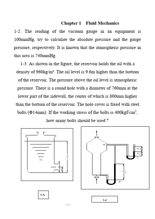
Chapter 1 Fluid Mechanics1-2.The reading of the vacuum gauge in an equipment is 100mmHg, try to calculate the absolute pressure and the gauge pressure, respectively. It is known that the atmospheric pressure in this area is 740mmHg.1-3.As shown in the figure, the reservoir holds the oil with a density of 960kg/m³. The oil level is 9.6m higher than the bottom of the reservoir. The pressure above the oil level is atmospheric pressure. There is a round hole with a diameter of 760mm at the lower part of the sidewall, the center of which is 800mm higher than the bottom of the reservoir. The hole cover is fixed with steel bolts (Φ14mm). If the working stress of the bolts is 400kgf/cm2,how many bolts should be used ?1-4. There are two U-tube differential pressure meters fixed on the fluid bed reactor, as shown in the figure. It is measured that the reading is R1=400mm,R2=50mm, respectively. The indicating liquid is mercury. To avoid the mercury vapor diffusing in the air, water is injected in the U-tube which is connected with air on the right side, and the height R3=50mm. Try to calculate the pressure at point A and B.1-5.As shown in the figure, the manometric tubes are connected with the equipment A , B, C, respectively. The indicating liquid in the tubes is mercury, while on the top of the tube is water, water surface of the three equipments is at the same level. Try to determine:1)Is the pressure equal with each other at the point 1, 2 and 3?2)Is the pressure equal with each other at the point 4, 5 and 6?3)If h1=100mm, h2=200mm, and equipment A is open to the atmosphere (the atmospheric pressure is 760mmHg), try to calculate the pressure above the water surface in equipment B and C.1-6. As shown in the figure, the steam pressure above the boiler is measured with the U-tube differential pressure meters in series. The indicating liquid in the differential pressure meter is mercury, the connecting tube between the two U-tube meters is full of water.Given that the vertical distance between the mercury levels and the referring level is h 1=2.3m, h 2=1.2m, h 3=2.5m, h 4=1.4m respectively. The vertical distance between the water level in the boiler and the base level is h 5=3m. The atmospheric pressure Pa is 745mmHg. Try to calculate the vapor pressure P 0 above the water level in the boiler.(inN/m²,respectively.)2/364400m N1-7. Based on the reading of the differential pressure meter as shown in the figure, calculate the gauge pressure of the gas in the tube line. The indicating liquids in the differential pressure meter are oil and water, with the density of 920kg/m³ and 998kg/m³, respectively. The distance between the water and oil interfaces in the U-tube R is 300mm. The inner diameter of the expansionchambers is 60mm, and that of the U-tube is 6mm . When the gas pressure in the tube line is equal to the atmospheric pressure, the liquid level in the two expansion chambers is even with each other. 20m /N 257003.081.99203.081.9)920998(P =⨯⨯+⨯⨯-=1-8. The tube bundle of a tubular heat exchanger is constituted of 121 steel tubes (Φ25×2.5mm). The air with an average temperature of 50℃ flows in the tube bundle at 9m/s. The pressure of the air is 2kgf/cm²(gauge pressure). The local atmospheric pressure is 740mmHg . Try to calculate :1) The mass flow of the air;(质量流量)2) The volume flow rate of the air under the operation condition;(体积流量)1-9. The gas at the average pressure of 1atm flows in the pipe (Φ76⨯3mm). Now the average pressure is changed to 5atm , if it is required that the gas flows at the same temperature, rate and mass velocity , what should the inside diameter of the tube be?1-10. The feeding liquid with a density of 850kg/m³ is sent into the tower from the elevated tank (储槽). The liquid level in the elevated tank keeps constant. The gauge pressure in the tower is 0.1kgf/cm², and the feeding rate is 5m³/h . The connecting pipe issteel pipe (Φ38⨯2.5mm), the energy loss in the connecting pipe of the feed liquid is 30J/kg (the energy loss in the exit is not included). What is the distance between the liquid level of the elevated tank and the feeding inlet?1-11. The water level in the elevated tank is 8m highe r than the floor. Water flows out of the pipeline (Φ108⨯4mm), of which the outlet is 2m higher than the floor. Under the given condition, the energy loss of the water flowing through system (the energy loss of the outlet is not included) can be calculated with Σh f=6.5u², where u is the water velocity (in m/s). Try to calculate:1)The water velocity at the section A-A’;2)The flow rate of water (in m3/h).1-12. Water with a temperature of 20℃ flows through the horizontal pipe (Φ38⨯2.5mm) at 2.5m/s . The pipe is connected with another horizontal pipe (Φ53⨯3mm) t hrough a conical pipe. As shown in the figure, two vertical glass tubes are inserted at section A and B on either side of the conical pipe, respectively. If the energy loss when water flows through section A and B is1.5J/kg, try to calculate the distance between the two water levels in the glass tubes (in mm)? Draw out the relative position of the water level in the figure.O m m H p p A B 26.88798.9/5.868==-A B p p >1-13. Water at 20℃ is sent to the top of the scrubber from the reservoir with a centrifugal pump. The water level in the reservoir keeps constant, as shown in the figure. The diameter of the pipeline is Φ76⨯2.5mm. Under the operation condition, the reading of the vacuum gauge at the pump entrance is 185mmHg . The energy loss when water flows through the suction tube (The entrance of the pipe is not included) and the discharge tube can be calculated according to formula Σh f,1=2u² and Σh f‚2=10u², where u is the water velocity in the suction or discharge tube. The gauge pressure at thejoint of the discharged tube and the spray nozzle is 1kgf/cm 2. Try to calculate the effective power of the pump. kW W w W N s e e 26.2226092.74.285==⨯==1-15. A cooling brine circulating system is shown in the figure. The density of the brine is 1100kg/m³, and the circulation is 36m³/h. The diameter of all the pipelines is the same. The energy loss when the brine flows from point A to B through two heat exchangers is 98.1J/kg, and the loss when the brine flows from B to A is 49J/kg. Try to calculate:1) If the efficiency of the pump is 70%, what is the shaft power of it?(in kw)2) If the reading of the manometer at point A is 2.5kgf/cm², what is the reading of the manometer at point B?1-17. Liquid with a density of 850kg/m³, and a viscosity of 8cp flows in the steel pipe (the inside diameter is 14mm). The liquid velocity is 1m/s. Try to calculate:1) The Reynolds number, and point out the flow pattern.2) The position where the local velocity is equal to the average velocity.3) Suppose the pipeline is a horizontal pipe, and the pressure of the upstream is 1.5kgf/cm², How long the liquid has to flow through when the pressure drop to 1.3kgf/cm²?1-18. As shown in the figure, an inverse U-tube differential pressure meter is fixed between the cross sections of two horizontal pipes with different diameters in order to measure the pressure difference of the two cross sections. When the flow rate is 10800kg/h, the reading of the differential pressure meter is 100mm. The diameters of the two pipe are Φ60⨯3.5mm and Φ42⨯3mm, respectively. Calculate :1) The energy loss of 1kg water flowing through the two cross sections;2) The pressure drop which is correspondent to the energy loss (in N/m²).1-19. Liquid is flowing laminarly in a straight pipe. If the pipelength and the physical property keeps constant, with the diameter decreases to half of the original, how many times is the energy loss aroused by the flow resistance as much as the original?1-22.Liquid is sent to the elevated tank from the reactor with a pump at 2⨯104kg/h (as shown in the figure). The pressure above the liquid surface in the reactor keeps a vacuum of 200mmHg, and that above the liquid surface in the elevated tank is the atmospheric pressure. The pipeline is the steel pipe(Φ76⨯4mm), with the length of 50m. There are two wide open brake valves, a orifice meter (the resistance coefficient is 4), five standard elbows in the pipeline. The vertical distance from the liquid surface in the reactor to the exit of the pipeline is 1.5m. If the efficiency of the pump is 0.7, try to calculate the shaft power of the pump. It is given that the density of the liquid is 1073kg/m³, the viscosity is 0.63cP, and the absolute roughness of the pipe wall ε is 0.3mm.1-23. There are a few solvents in the exhaust gas discharged from the equipment. Before vented to the atmosphere, the gas is sent through a washing tower in order to recover the solvents and avoid the environmental pollution. The flow rate of gas is 3600m³/h (under the operation condition), and the physical property of gas is almost the same as that of air at 50℃. As shown in the figure, a U-tube differential pressure meter with the indicating liquid ofwater is fixed in the pipeline before the gas entering the blower. The reading of the meter is 30mm. The inside diameters of both the delivering pipe and the venting pipe are 250mm. The total equivalent length of the pipe line, fitting, and valves is 50m (The resistance of entering and leaving the tower is not included),and the vertical distance between the vent and the entrance of the blower is20m. Suppose the pressure drop of the gas through the filler layer in the tower is 200mm H2O, the absolute roughness of the pipe wall εcan be taken as 0.15mm and the atmospheric pressure is 1atm, try to calculate the effective power of t he blower (风机).1-24.As shown in the figure, the water level in the reservoir keeps constant. A steel drainpipe (with the inside diameter of 100mm) is connected to the bottom of the reservoir. There is a gate valve fixed in the pipeline, and a U-tube differential meter with the indicating liquid of mercury is fixed at the position 15m away from the entrance of the pipeline. One part of the differential meter is connected to the pipe, and the other is connected to air. The connecting tube of the differential pressure meter is full of water. The length of the straight pipe between the pressure measuring point and the outlet of the pipeline is 20m.a)When the gate valve is closed, R=600mm, h=1500mm; when the gate valve is opened partly, R=400mm, h=1400mm. The friction coefficient λ is 0.025, and the local resistance coefficient at the entrance of the pipeline is 0.5. Calculate the flow rate of water when the gate valve is opened partly. (in m³/h)b)When the gate valve is widely open, calculate the static pressure at the pressure measuring point (in gauge pressure, N/m²). It is given that le/d≈15when the gate valve is widely open, and the frict ion coefficient λ is still 0.025.2)The pressure at the pressure measuring point when the gate valve is widely open.1-26.Water at 20℃passes through a steel pipe with an insidediameter of 300mm. There is a branch pipe(Φ60 3.5mm) which is parallel with the main pipe. The total length including all the local frictional loss of the branch pipe is 10m. A rotameter is fixed in the branch pipe. From the rotameter, the flow rate of water is 2.72m3/h. Try to calculate the flow rate in the main pipe and the total flow rate, respectively. The frictional coefficient of the main pipe and the branch pipe is 0.018 and 0.03, respectively.Chapter 2 Fluid Transportation2-1. water is used in the experiment to measure the property of pump. As the flow rate is 26m3/h, the reading of piezometer at the exit of the pump is 152 kPa and the reading of vacuum gauge at the entry of the pump is 24.7 kPa.The shaft power is 2.45kw, rotational speed is 2900r/min, respectively. If the vertical distance between the vacuum meter and piezometer is 0.4m, the pipeline diameters of the entry and exit of pump are the same. The frictional resistance between two gauges is negligible. Calculate the efficiency of pump and list the performance of the pump under this efficiency.2-2. Hot water at 60℃in reservoir is sent by a centrifugal pump at the flow rate of 40m3/h to thetop of a cooling water tower, then is sprayed by a sprayer and drops into a cooling reservoir,so that the hot water is cooled. Given the gage pressure maintains 49kPa before water enter the sprayer, the inlet of sprayer is 0.5m above the level of hot water in the reservoir. The total head loss of inhalation pipeline and vent pipeline is 1m and 3m respectively, and the kinetic head in pipeline can be negligible.Try to select a fitting centrifugal pump and determine the installation height. Suppose the local atmosphere pressure is 101.33kPa.(=3.77m)2-3. Oil products are filled in a groove under the normal pressure, the density is 760kg/m3, absolute viscosity is less than 20cp. Under the operating condition, the saturated vapor pressure is 80kPa. Now the oil would be sent by 65Y-60B oil pump into an equipment in which the gauge pressure is 1.8mH2O. The level of oil in the groove is invariability. The entry of the equipment is 5m above the level of oil in the groove. The total heads loss of inlet pipeline and outlet pipeline is 1m and 4m respectively. Try to calculate whether the pump can work normally.If the oil pump is 1.2m below the level of oil in the groove, whether the pump can be operated normally? Suppose the local atmosphere pressure is 101.33kPa.Based on the table of textbook, the capability of 65Y-60B oil pump is listed as followsFlow rate, m³/h 19.8Total head, m 38Shaft power, kW 3.75Efficiency, % 55Cavitation, m 2.6(65Y-60B oil pump is operable ).m H g 74.016.281.976010)8.00133.1(5-=--⨯⨯-= The actual suction lift is -1.2m < -0.74m, which means the pump can operate normally .。
《渗流力学》中英文课程简介英文名称:Fluid mechanics in porous medium of oil and gas 课程编号:适用专业:石油工程专业学时:54 学分: 3 实验学时: 8 课内上机学时:10一、预修课程开发地质学、流体力学、油藏物理二、中文内容提要《渗流力学》是油田开发和开采专业的主要专业基础课之一。
其任务是要使学生掌握水驱、弹性驱以及溶解气驱方式下地层流体的运动规律、产能的计算和通过不稳定试井方法确定地层参数。
为学生毕业后正确根据地层性质、流体性质和地质条件,选择合理的数学模型,研究流体运动规律并进行动态预测作准备。
为解决油田开发过程中的实际问题和从事科研工作准备必要的专业理论知识。
三、英文内容提要(5号黑体)‘Fluid mechanics in porous medium of oil and gas’ is one of the main basic courses of major oil and gas development and exploitation. The mission of the course is to guide students to master the kinematical law of formation fluid under circumstances of water flooding, elastic drive and depletion drive, master the deliverability calculation and determine formation parameters through method of non-stabilized well test. According to this course, students can set a good preparation for how to choose a reasonable model to study the laws of fluid motion and how to make a dynamic prediction using formation characteristics, fluid properties and geological conditions. The content of this course is the necessary speculative knowledge for solving practical problems and doing research work in process of oil-field development.四、教材:《油气渗流力学基础》,李璗主编,陕西科学技术出版社,2001.五、教材类别:自编制订者(签字):校对者(签字):审定者(签章):批准者(签章):。
在撰写学术论文或报告时,引用文献是一个重要的环节。
EndNote 是一款广泛使用的文献管理软件,它可以帮助用户整理和管理文献资料,并生成符合各种期刊要求的引用格式。
对于《Journal of Fluid Mechanics》这篇期刊,您需要使用正确的引用格式,以确保您的论文能够顺利通过同行评审和发表。
通常,《Journal of Fluid Mechanics》接受的引用格式是按照学术出版协会(如APA、MLA、Chicago等)的标准来标注的。
EndNote 提供了这些标准的引用格式模板,您可以选择相应的模板来格式化您的文献引用。
以下是使用EndNote 格式化《Journal of Fluid Mechanics》引用的一般步骤:1. 打开EndNote,并选择“文件”菜单中的“新建文献”选项。
2. 在新建的文献记录中,输入您的文献信息,包括作者、标题、出版年份、卷号、期号、页码等。
3. 在“引用类型”或“文献类型”菜单中,选择“期刊文章”或《Journal of Fluid Mechanics》的具体引用格式模板。
4. 输入所有必要的文献信息,并确保所有的字段都准确无误。
5. 完成后,点击“添加到文献库”或“保存”按钮来保存您的文献记录。
6. 您可以在论文中通过EndNote 插件或命令来插入已经格式化的引用。
EndNote 用户还可以自定义引用格式,如果《Journal of Fluid Mechanics》有特定的引用格式要求,您可以根据期刊提供的指南在EndNote 中进行相应的设置。
正确的引用格式不仅仅是为了美观,更是学术诚信的体现。
确保您的引用准确、完整,并且遵循期刊的具体要求。
在提交论文之前,建议您仔细检查所有的引用,并确保它们符合《Journal of Fluid Mechanics》的引用规范。
新能源科学与工程专业本科培养计划Undergraduate Program for Specialty in New Energy Science and Engineering一、培养目标Ⅰ.Educational Objectives本专业着重培养集清洁与可再生能源科学及工程知识与现代信息技术为一体的跨学科复合型高级技术人才和管理人才。
毕业生能在电力、动力、汽车、化工、冶金、机械等部门从事节能减排和太阳能、风能、生物质能等新能源及自动化等相关方面的的研究、教学、设计、开发、管理和营销等工作。
This program is designed to prepare cultivation of compound interdisciplinary top-ranking technicians and managers of both clean energy & renewable energy science and power engineering knowledge and modern information technique. Students can pursue a career in departments related to electric power, cryogenic refrigenration, automotive ergineering, fluid machinery, metallurgy, chemical industry, medicine and other various sectors. Students are quealified for jobs concerning research, teaching, design, development, and management on energy saving, emissions reduction, solar energy, wind energy, bioenergy, automotive ergineering and other various sectors.二、基本规格要求Ⅱ.Skills Profile1、具有一定的人文社会科学和自然科学基本理论知识,特别是有较好的人文素质;2、系统地掌握本专业必需的技术基础理论,主要包括力学、热学、电工与电子、自动控制及能源动力工程基础理论等;3、熟悉本专业领域内1~2个专业方向或有关方面的专业知识,了解其学科前沿和发展趋势;4、具有本专业必需的制图、计算、测试、调研、查阅文献和基本工艺、操作、运行等基本技能;5、掌握一门外国语,要求能阅读专业书刊,并有一定的听说能力,对于英语应达到国家四级以上水平(含四级);6、具有一定计算机相关知识和较强的计算机应用能力,能熟练使用计算机解决工程中的有关·167·问题;7、具有较强的自学能力、分析能力和创新意识。