H-1-4TNC中文资料
- 格式:pdf
- 大小:99.74 KB
- 文档页数:1
![1海德汉中文使用说明书[1]](https://img.taocdn.com/s1/m/2933bb4c0b4e767f5acfcedc.png)
1前言1.1TNC 426,TNC 430HEIDENHAIN TNC是一种面向生产车间的仿型控制器,使您能以一种便于使用的对话式编程语言,编制使机床准确加工运转的对话式程序。
TNC控制器可用于铣削、钻孔和镗削加工,也可用于加工中心。
TNC 426最多可控制五根轴;TNC 430最多可控制九根轴。
您也可在程序控制下改变主轴的角度位置。
一体化的硬盘能存储许多您所喜欢的程序,不论这些程序是脱机创建的还是数字化的。
为了能快速计算,随时随地都能在屏幕上调出袖珍计算器。
键盘和屏幕布局清晰合理,功能调用快捷,使用方便。
编程:HEIDENHAIN对话式和ISO格式HEIDENHAIN对话式编程是一种特别容易的程序写入方法,交互式的图形表示仿型编程的各个加工步骤。
如果某一张生产图纸没有标注NC适用的尺寸,HEIDENHAIN FK任意形状轮廓编程就会自动执行必要的计算。
工件的加工状况,无论是现在正在加工中还是在加工之前,都能用图形模拟显示。
在ISO编程格式或DNC模式中都由此功能。
当TNC在运行另一段程序时,您也可输入或测试一段程序。
兼容性TNC能执行所有写在TNC 150B及以后的HEIDENHAIN 控制器上的零件程序。
1.2可视显示器和键盘可视显示器TNC显示器可使用CRT彩色显示器(BC120)或TFT 液晶显示器(BF120)。
右上图为BC120的键盘和控制器,右中图为BF120的键盘和控制器。
屏幕端部当TNC接通电源时,屏幕端部显示选定的操作方式:左侧为加工方式,右侧为编程模式。
当前激活的模式显示在一个较大的方框中,在此方框中,同时也显示对话提示和TNC信息(如果没有,则仅显示图形)。
软键TNC底部一排软键表示辅助功能。
直接按下这些键,即可选用这些辅助功能。
紧接着软键行上面的行表示软键的编号,可以左右移动黑色光标调用。
被激话的软键行高亮显示。
软键选择键切换软键行设置屏幕布局用于转换加工和编程模式的移位键仅在BC120上的键屏幕退磁:为屏幕设置退出主菜单为屏幕设置选择主菜单:在主菜单中:高亮显示部向下移动在子菜单中:减小数值;图形向左或向下移动在主菜单中:选择子菜单在子菜单中:退出子菜单主菜单对话功能BRIGHTNESS调节亮度CONTRAST调节对比度H-POSITION调节水平位置主菜单对话功能V-POSITION 调节图形高度V-SIZE调节图形高度SIDE-PIN纠正桶型失真TRAPEZOID纠正梯形失真ROTATION纠正倾斜COLOR TEMP调节色温R-GAIN调节红色浓度B-GAIN调节兰色浓度RECALL无功能BC120对磁场和电噪声敏感,可能会使图形的位置和几何形状产生失真。
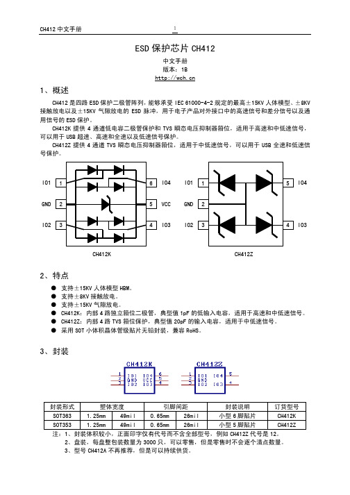
ESD 保护芯片CH412中文手册 版本:1B 1、概述CH412是四路ESD 保护二极管阵列,能够承受IEC 61000-4-2规定的最高±15KV 人体模型、±8KV 接触放电以及±15KV 气隙放电的ESD 脉冲,用于电子产品对外接口中的高速信号和差分信号以及通用信号的ESD 保护。
CH412K 提供4通道低电容二极管保护和TVS 瞬态电压抑制器箝位,适用于高速和中低速信号,可以用于USB 超速、高速和全速以及低速信号保护。
CH412Z 提供4通道TVS 瞬态电压抑制器箝位,适用于中低速信号,可以用于USB 全速和低速信号保护。
CH412K CH412Z2、特点● 支持±15KV 人体模型HBM 。
● 支持±8KV 接触放电。
● 支持±15KV 气隙放电。
● CH412K :内部4路独立箝位二极管,典型值1pF 的低输入电容,适用于高速和中低速信号。
● CH412Z :内部4路TVS 箝位保护,典型值20pF 的输入电容,适用于中低速信号。
● 采用SOT 小体积晶体管级贴片无铅封装,兼容RoHS 。
3、封装封装形式 塑体宽度 引脚间距 封装说明 订货型号 SOT363 1.25mm 49mil 0.65mm 26mil 小型6脚贴片 CH412K SOT353 1.25mm 49mil 0.65mm 26mil 小型5脚贴片 CH412Z 注:1、封装体积较小,正面印字仅有代号而不含全部型号,例如CH412Z 代号是12。
2、盘装,每盘整包装数量为3000只,可以零售,但是零售时不会逐个清点数量。
IO4 IO3 IO3 VCC IO44、型号CH412B已经停产,请换用CH412K,多出的两个通道可以悬空或并联(低速时)。
4、引脚CH412K 引脚号CH412Z引脚号引脚名称类型引脚说明2 2 GND 电源公共接地端,必须直接连接到全局地5 无VCC 电源正电源端,必须靠近引脚对GND连接0.1μF电容,用于USB信号保护时通常为3.3V(或者5V),用于其它信号须同被保护芯片的电源电压(2V~5V)1,3,4,6 1,3,4,5 IO1~IO4 信号ESD保护通道,与被保护芯片的信号引脚并联5、应用说明CH412设计用来与被保护芯片内置的ESD保护一起工作。
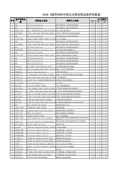

欧姆龙PLC样本与手册全集小型机CP1H选型样本(中文)r05-cn-03cp1h/cp1l选型样本(中文)sbca-c-051dcp1l选型样本(英文)p20e-en-01cp1e中英文选型样本cp1h操作手册(中文)w450-cn5-02cp1h操作手册(英文)w450-e1-01cp1l操作手册(中文)w462-cn5-03cp1l操作手册(英文)w462-e1-06Cp1e单元软件用户手册(中文和英文)w480-e1-01w480-cn5-01cp1e单元硬件用户手册(中文和英文)w479-e1-01w479-cn5-01cp1e单元硬件用户手册(英文)(包括Na)w479-e1-03cp1h/cp1l编程手册(英文)w451-e1-03cp1h/cp1l编程手册(中文)cp1e指令参考手册(中文)w483-cn5-04cp1e指令手册(英文)Cpm1a-v1选型样本(英文)p039e1-11cpm1a操作手册(英文)w317-e1-4cpm1/1a/2a/2c/srm1编程手册(英文)w353-e1-1cpm1a操作手册(中文)omp-zco97101bcpm1a/2a/2ah/2c编程手册(中文)cpm1操作手册(英文)w262-e1-4cpm2a/2c选型样本(英文)p049-e1-08cpm2ah选型样本(中文)Cpm2ah-s选型样本(中文)P01z-cn-01cpm2a操作手册(英文)w352-e1-1cpm2ah-s操作手册(中文)CPM2A/Cpm2ah操作手册(中文)cpm2c选型样本(英文)cpm2c操作手册(英文)w356-e1-08cpm2b操作手册(中文)omp-ad000102acpm2b-s001m-drt操作手册(英文)w399-e1-1中型计算机cj1系列选型样本(中文)Cj2h/cj2m选型样本(中文)sbce-cn-058dc200hx/c200hg/c200he选型样本(中文)cj1m内置i/o操作手册(中文)w395-c1-01cj1操作手册(中文)w393-c1-02cj1编程手册(中文)w340-c1-08cj1最新编程手册(英文)w340-e1-1Cj2cpu装置硬件操作手册(中文)w472-cn5-06cj2操作手册(英文)w472-e1-01cj2m MD操作手册(英文)w486-e1-01cj2编程手册(英文)w473-e1-01cj1w AD/DA操作手册(中文)w345-c1-05cj1w TC操作手册(中文)w396cj1w PTS操作手册(英文)w368-e1-07c200hx/Hg/he编程手册(中文)Oez-zcp97201ac200he/Hg/HX操作手册(中文)Oez-zci96201ac200h模拟量(ad001/da001)操作手册(中文)omp-zco99406ac200h模拟量i(ad003/da003)操作手册(英文)w325-e1-04c200h-tc温度控制单元操作手册(英文)w124-e1-5c200h操作手册(英文)w130-e3-5c200hs安装手册(英文)c200hs操作手册(英文)cqm1h选型样本(中文)cqm1h操作手册(中文)cqm1h编程手册(中文)Cqm1h系列CPU及内置板操作手册(英文)Cqm1h系列CPU及内置板编程手册(英文)Cqm1h专用I/O单元操作手册(中文)Cqm1h/CQM1专用I/O手册(英文)大型机Cs1w PTS过程控制I/O模块操作手册(英文)w368-e1-07cs1-h型号选择样本(中文)cs1d型号选择样本(中文)cs1可编程控制器操作手册(中文)w339-cn5-10cs1编程手册(中文)w340-c1-08cs1最新编程手册(英文)Cs1d双机操作手册(英文)w405-e1-06cs1w AD/DA操作手册(中文)w345-c1-05cs1w AD/DA最新操作手册(英文)w345-e1-11c500安装手册(英文)w132-e1-3dc500编程手册(英文)w131-e1-02c500-lk操作手册(英文)w143-e1-05串行通信cs1/cj1w-scu/scb串行通讯单元/板卡操作手册(英文)-w336-e1-10cqm1h-scb41操作手册(英文)-w365-e1-02nt-al001使用手册(英文)C200hpc链路系统手册(英文)-w135-e1-2b以太网Cs1-etn01/11和cj1-etn11操作手册(英语)-w343-e1-07cs1/cj1-etn21操作手册(英语)-w420-e1-06cs1/cj1-etn21应用手册(英语)-w421-e1-04cs1d-etn21d操作手册(英语)-w430-e1-02cj1m-cpu1□ - ETN操作手册(英文)-w441-e1-03controllerlink3g8f7-clk21/52/12安装指南(英文)w388-e1-2c200hw/cvm1-clk21操作手册(中文)-oez-zco97404acs/cj1w/c200hw/cvm1/cqm1h-clk21cs1w-rpt01/02/03操作手册(英文)-w309-e1-113g8f7-clk12/21/52(-EV1)/13/23/53(-E)操作手册(英文)-w383-e1-04cs1w/cvm1-clk12/52/13/53操作手册(英文)-w370-e1-07cs1/cj1-drm21-v1操作手册(英文)-w380-e1-07Cvm1/c200hw-drm21/cqm1-drt21drt1系列操作手册(英文)-w267-e1-6cs1/CJ1系列drm21操作手册(中文繁体)-sbcd-314h-tw5-01itnc-epx01/itnc-epx01-drm开放网络控制器操作手册(英文)-v228-e1-02c200hw/cqm1-drt21/drt1系列操作手册(英文)-w347-e1-06devicenet操作手册(英文)-w267-e1-113g3mv-pdrt1-sinvdevicenet通信单元操作手册(英文)-i529-e1-02drt2系列从机单元操作手册(英文)-w404-e1-08nt-drt21devicenet接口单元操作手册(英文)-v066-e1-13g3fv-pdrt1-sin操作手册(英文)-i525-e1-023g3mv/3g3rv-pdrt2devicenet操作手册(英文)-i539-e1-03grt1-drt模块操作手册(英文)-w455-e1-06Omnucw系列伺服驱动器r88a-ncw152-drt操作手册(英文)-i538-e1-01omnucw系列伺服驱动器r88a-ncw152-drt选择样本(英文)-ds13p1cs/cj1w-drm21 AB公司drt集群站安装说明(英文)c200hw/cj1/cqm1-srm21srt1/srt2操作手册(英文)-w226-e1-09CS/cj1w-crm21操作手册(英文)-w456-e1-03profibus-dp。

组串式逆变器技术规范书协鑫新能源系统有限公司2014年08月目录1总则 (1)2 设备规范 (1)2.1设备名称 (1)2.2型式(或型号)、用途和安装数量 (2)2.3参数 (2)3设备的运行环境条件 (2)3.1工程概况 (2)3.2厂址条件 (2)3.3安装运行条件 (2)4 技术要求 (2)4.1技术条件 (2)4.2性能要求 (5)4.3经济要求(主要指能耗等) (7)4.4结构要求 (7)4.5配供驱动机要求 (7)4.6设备材质要求 (8)4.7仪表和控制要求 (8)4.8安装调试要求 (8)4.9其它要求(噪音) (8)5 供货范围 (8)5.1一般要求 (8)5.2供货范围 (9)5.3备品备件 (10)5.4专用工器具(卖方填写) (10)6 质量保证及试验 (10)6.1设计、制造应遵守的规程、规范和标准 (10)6.2设备性能、质量保证 (12)6.3设备的试验及要求 (12)6.4其它 (12)7 油漆、包装和运输 (12)7.1油漆和防腐 (12)7.2包装 (12)7.3运输 (13)8 技术资料和交付进度 (13)8.1一般要求 (13)8.2卖方应提供的技术文件内容、数量、时间 (14)9 交货进度 (14)10 监造(检验)和性能验收试验 (15)10.1监造依据 (15)10.2监造方式 (15)10.3监造内容 (15)10.4对卖方配合监造的要求 (15)10.5性能验收试验 (16)11 技术服务和联络 (16)11.1卖方现场技术服务 (16)11.2培训 (17)11.3设计联络 (18)11.4售后服务 (18)12 分包商/外购部件情况 (18)13 大件部件情况 (18)14 技术规范书的基本响应方式 (19)14.1对技术规范响应方式的基本要求 (19)15 差异表 (19)1总则1.1本招标文件适用于并网光伏发电项目的并网组串逆变器,它提出了该设备的功能设计、结构、性能、安装和试验等方面的技术要求。

化学品安全技术说明书第1部分化学品及企业标识化学品中文名:1,1,2,2-四溴乙烷化学品英文名:1,1,2,2-Tetrabromoethane企业名称:此处填写贵公司名称企业地址:此处填写贵公司地址传真:此处填写贵公司传真联系电话:此处填写贵公司电话企业应急电话:此处填写贵公司应急电话产品推荐及限制用途:For industry use only.。
第2部分危险性概述紧急情况概述:造成严重眼刺激。
吸入致命。
GHS危险性类别:严重眼损伤/ 眼刺激类别 2急性吸入毒性类别 2危害水生环境——长期危险类别 3标签要素:象形图:警示词:危险危险性说明:H319 造成严重眼刺激。
H330 吸入致命。
H412 对水生生物有害并具有长期持续影响。
防范说明:•预防措施:•P264 作业后彻底清洗。
•P280 戴防护手套/穿防护服/戴防护眼罩/戴防护面具。
•P260 不要吸入粉尘/烟/气体/烟雾/蒸气/喷雾。
•P271 只能在室外或通风良好处使用。
•P284 [在通风不足的情况下] 戴呼吸防护装置•P273 避免释放到环境中。
•事故响应:•P305+P351+P338 如进入眼睛:用水小心冲洗几分钟。
如戴隐形眼镜并可方便地取出,取出隐形眼镜。
继续冲洗。
•P337+P313 如仍觉眼刺激:求医/就诊。
•P304+P340 如误吸入:将人转移到空气新鲜处,保持呼吸舒适体位。
•P310 立即呼叫解毒中心/医生•P320 紧急具体治疗 ( 见本标签上的…… )。
•安全储存:•P403+P233 存放在通风良好的地方。
保持容器密闭。
•废弃处置:•P501 按当地法规处置内装物/容器。
物理和化学危险:无资料健康危害:造成严重眼刺激。
吸入致命。
环境危害:对水生生物有害并具有长期持续影响。
第3部分成分/组成信息第4部分急救措施急救:吸入: 如果吸入,请将患者移到新鲜空气处。
皮肤接触: 脱去污染的衣着,用肥皂水和清水彻底冲洗皮肤。

SHT4x4th Generation, High-Accuracy, Ultra-Low-Power, 16-bit Relative Humidity and Temperature SensorFeatures• Relative humidity accuracy: up to ±1.5 %RH • Temperature accuracy: up to ±0.1 °C • Supply voltage: 1.08 V … 3.6 V • Average current: 0.4 µA (at meas. rate 1 Hz) • Idle current: 80 nA• I2C fast mode plus, CRC checksum• Operating range: 0…100 %RH, -40…125 °C • Fully functional in condensing environment • Variable power heater • NIST traceability• JEDEC JESD47 qualification• Mature technology from global market leaderGeneral DescriptionSHT4x is a digital sensor platform for measuring relative humidity and temperature at different accuracy classes. The I2C interface provides several preconfigured I2C addresses and maintains an ultra-low power budget. The power-trimmed internal heater can be used at three heating levels thus enabling sensor operation in demanding environments. The four-pin dual-flat-no-leads package is suitable for surface mount technology (SMT) processing.Device OverviewFunctional Block DiagramFull product list on page 15ContentsFeatures (1)General Description (1)Device Overview (1)Functional Block Diagram (1)1 Quick Start – Hello World (3)2 Humidity and Temperature Sensor Specifications (4)2.1 Relative Humidity (4)2.2 Temperature (5)2.3 Recommended Operating Conditions (6)3 Electrical Specifications (6)3.1 Electrical Characteristics (7)3.2 Timings (7)3.3 Absolute Maximum Ratings (8)4 Sensor Operation (8)4.1 I2C communication (8)4.2 Data type & length (9)4.3 Checksum Calculation (9)4.4 Command Overview (10)4.5 Conversion of Signal Output (10)4.6 Serial number (11)4.7 Reset & Abort (11)4.8 Heater Operation (11)5 Physical Specification (12)5.1 Package Description (12)5.2 Package Outline (12)5.3 Land Pattern (12)5.4 Pin Assignment & Laser Marking (13)5.5 Thermal Information (14)6 Quality and Material Contents (14)7 Tape and Reel Packaging (14)8 Product Name Nomenclature (15)9 Ordering Information (15)10 Bibliography (15)11 Revision History (16)1 Quick Start – Hello WorldA typical application circuit for SHT4x is shown on the left-hand side of Figure 1. After reaching the minimal supply voltage and allowing for the maximal power-up time of 1 ms the sensor is ready for I2C communication. The quickest way to measure humidity and temperature is pseudo-coded on the right-hand side of Figure 1. Together with the conversion formulae given in equations ( 1 ), ( 2 ), and ( 3 ), the digital signals can be translated into relative humidity and temperature readings.the signal cropping in the last four lines see section 4.5.Find code resources and embedded drivers on: https:///Sensirion/embedded-sht/releasesCAD files can be downloaded from SnapEDA: https:///parts/SHT40-AD1B-R3/Sensirion/view-part/2 Humidity and Temperature Sensor SpecificationsEvery SHT4x is individually tested and calibrated and is identifiable by its unique serial number (see section 4.6 for details on the serial number). For the calibration, Sensirion uses transfer standards, which are subject to a scheduled calibration procedure. The calibration of the reference, used for the calibration of the transfer standards, is NIST traceable through an ISO/IEC 17025 accredited laboratory.2.1 Relative HumidityTable 1: General relative humidity sensor specifications.Figure 2: SHT40 typical and maximal relative humidity accuracy at 25 °C. Figure 3: SHT41 typical and maximal relative humidity accuracy at 25 °C.1For definition of typ. and max. accuracy, please refer to the document “Sensirion Humidity Sensor Specification Statement”.2The stated repeatability is 3 times the standard deviation (3σ) of multiple consecutive measurement values at constant condit ions and is a measure for the noise on the physical sensor output. Different repeatability commands are listed in Table 7.3Valid for 25°C and 50%RH.4Resolution of A/D converter.5 Specified range refers to the range for which the humidity or temperature sensor specification is guaranteed.6For details about recommended humidity and temperature operating range, please refer to section 2.3.7Time for achieving 63% of a humidity step function, measured at 25°C and 1 m/s airflow. Humidity response time in the application depends on the design-in of the sensor.8Typical value for operation in normal RH/T operating range. Max. value is < 0.5 %RH/y. Value may be higher in environments with vaporized solvents, out-gassing tapes, adhesives, packaging materials, etc. For more details please refer to Handling Instructions.Relative Humidity Accuracy at the Extended Temperature RangeThe typical RH accuracy tolerances in the range of T=0°C … 80 °C are given in Figure 6 and Figure 7.SHT40 |typ. Delta %RH| R e l a t i v e H u m i d i t y (%R H )100 390 280 70 60 50 1.8 40 30 20 210 0 3 01020304050607080Temperature (°C)SHT41 |typ. Delta %RH|R e l a t i v e H u m i d i t y (%R H ) 100 902 80 70 60 50 1.8 40 30 2010 2 01020304050607080Temperature (°C)Figure 4: Typical RH accuracy tolerance over humidity and temperature for SHT40. Figure 5: Typical RH accuracy tolerance over humidity and temperature for SHT41.2.2 TemperatureTable 2: General temperature sensor specifications.9 Temperature response time depends on heat conductivity of sensor substrate and design-in of sensor in application. 10 Max. value is < 0.04°C/y.Figure 6: SHT40 typical and maximal temperature accuracy. Figure 7: SHT41 typical and maximal temperature accuracy.2.3 Recommended Operating ConditionsThe sensor shows best performance when operated within the recommended normal temperature and humidity range of 5 °C … 60 °C and 20 %RH … 80 %RH, respectively. Long term exposure to conditions outside recommended normal range, especially at high relative humidity, may temporarily offset the RH signal (e.g. +3 %RH after 60 h at > 80 %RH). After returning into the recommended normal temperature and humidity range the sensor will recover to within specifications by itself. Prolonged exposure to extreme conditions may accelerate ageing.To ensure stable operation of the humidity sensor, the conditions described in the document (Sensirion, 2020) regarding exposure to volatile organic compounds must be met. Please note as well that this does apply not only to transportation and manufacturing, but also to operation of the SHT4x.3 Electrical SpecificationsValid for all electrical specifications: Typical values correspond to V DD = 3.3 V and T = 25 °C. Min. and max. values are valid in the full temperature range -40 °C … 125 °C and at declared V DD levels.3.1 Electrical CharacteristicsTable 3: Electrical specifications.3.2 TimingsMax. values are measured at -40°C and 1.08 V supply voltage (based on characterization).Table 4 System timing specifications.3.3 Absolute Maximum RatingsStress levels beyond those listed in Table 5 may cause permanent damage or affect the reliability of the device. These are stress ratings only and functional operation of the device at these conditions is not guaranteed. Ratings are only tested each at a time.Table 5: Absolute maximum ratings.4 Sensor Operation4.1 I2C communicationI2C communication is based on NXP’s I2C-bus specification and user manual UM10204, Rev.6, 4 April 2014. Supported I2C modes are standard, fast mode, and fast mode plus. Data is transferred in multiples of 16-bit words and 8-bit checksum (cyclic redundancy check = CRC). All transfers must begin with a start condition (S) and terminate with a stop condition (P). To finish a read transfer, send not acknowledge (NACK) and stop condition (P). Addressing a specific slave device is done by sending its 7-bit I2C address followed by an eighth bit, denoting the communication direction: “zero” indicates transmission to the slave, i.e. “write”, a “one” indicates a “read” request. Schematics of the I2C transfer types are sketched in Figure 8. The sensor does not support clock-stretching. In case the sensor receives a read header and is still busy with e.g. measurement or 11The recommended storage temperature range is 10-50°C. Please consult the document “SHTxx Handling Instructions” for more in formation.heating, it will return a NACK. Measurement data can only be received once and will be deleted from the sensor’s register after the first acknowledged I2C read header.Figure 8: I2C transfer types: First a write header is sent to the I2C slave, followed by a command, for example “measure RH&T with highest precision”. After the measurement is finished the read request directed to this I2C slave will be acknowledged and transmission of data will be started by the slave.4.2 Data type & lengthI2C bus operates with 8-bit data packages. Information from the sensor to the master has a checksum after every second 8-bit data package.Humidity and temperature data will always be transmitted in the following way: The first value is the temperature signal (2 * 8-bit data + 8-bit CRC), the second is the humidity signal (2 * 8-bit data + 8-bit CRC).4.3 Checksum CalculationFor read transfers each 16-bit data is followed by a checksum with the following propertiesTable 6 Data checksum properties.The master may abort a read transfer after the 16-bit data, if it does not require a checksum.4.4 Command OverviewTable 7 Overview of I2C commands. If the sensor is not ready to process a command, e.g. because it is still measuring, it will response with NACK to the I2C read header. Given heater power values are typical and valid for VDD=3.3V.4.5 Conversion of Signal OutputThe digital sensor signals correspond to following humidity and temperature values:RH=(−6+125∙S RH216−1)%RH( 1 )T=(−45+175∙S T216−1)°C( 2 )T=(−49+315∙S T216−1)°F( 3 )N.B.: The RH conversion formula (1) allows values to be reported which are outside of the range of 0 %RH … 100 %RH. Relative humidity values which are smaller than 0 %RH and larger than 100 %RH are non-physical, how ever these “uncropped” values might be found beneficial in some cases (e.g. when the distribution of the sensors at the measurement boundaries are of interest). For all users who do not want to engage in evaluation of these non-physical values, cropping of the RH signal to the range of 0 %RH … 100 %RH is advised.4.6 Serial numberEach sensor has a unique serial number, that is assigned by Sensirion during production. It is stored in the one-time-programmable memory and cannot be manipulated after production. The serial number is accessible via I2C command 0x89 and is transmitted as two 16-bit words, each followed by an 8-bit CRC.4.7 Reset & AbortA reset of the sensor can be achieved in three ways:•Soft reset: send the reset command described in Table 7.•I2C general call reset: all devices on I2C bus are reset by sending the command 0x06 to the I2C address 0x00.•Power down (incl. pulling SCL and SDA low)Any command that triggers an action at the sensor can be aborted via I2C general call reset or soft reset.4.8 Heater OperationThe sensor incorporates an integrated on-chip heater which can be switched on by the set of commands given in Table 7. Three heating powers and two heating durations are selectable. After reception of a heater-on command, the sensor executes the following procedure:1. The heater is enabled and the timer starts its count-down2. On timer expiration a temperature and humidity measurement with the highest repeatabilityis started, the heater remains enabled3. After the measurement is finished the heater is turned off4. Temperature and humidity values are now availableThe maximum on-time of the heater commands is 1 second, in order to prevent overheating of the sensor by unintended usage of the heater. Thus, there is no dedicated command to turn off the heater. For extended heating periods it is required to send periodic heater-on commands, keeping in mind that the heater is designed for a maximal duty cycle of less than 5%. To obtain a fast increase in temperature the idle time between consecutive heating pulses shall be kept minimal. Possible Heater Use CasesThere will be dedicated Sensirion application notes elaborating on various use cases of the heater. In general, the applications of the on-chip heater range around:1. Removal of condensed / spray water on the sensor surface. Although condensed water isnot a reliability / quality problem to the sensor, it will however make the sensor non-responsive to RH changes in the air as long as there is liquid water on the surface.2. Creep-free operation in high humid environments. Periodic heating pulses allow for creep-free high-humidity measurements for extended times.Important notes for operating the heater:1. The heater is designed for a maximum duty cycle of 5%, meaning the total heater-on-timeshould not be longer than 5% of the sensor’s lifetime.2. During operation of the heater, sensor specifications are not valid.3. The temperature sensor can additionally be affected by the thermally induced mechanicalstress, offsetting the temperature reading from the actual temperature.4. The sensor’s temperature (base tempe rature + temperature increase from heater) mustnot exceed T max = 125 °C in order to have proper electrical functionality of the chip.5. The heater draws a large amount of current once enabled (up to ~75mA in the highestpower setting). Although a dedicated circuitry draws this current smoothly, the powersupply has to be strong enough to avoid large voltage drops that could provoke a sensor reset.If higher heating temperatures are desired, consecutive heating commands have to be sent to the sensor. The heater shall only be operated in ambient temperatures below 65°C else it could drive the sensor outside of its maximal operating temperature.5 Physical Specification5.1 Package DescriptionSHT4x is provided in an open-cavity dual flat no lead (DFN) package. The humidity sensor opening is centered on the top side of the package. The sensor chip is made of silicon, hosted on a copper lead frame and overmolded by an epoxy-based mold compound. Exposed bottom side of the leadframe with the metallic contacts is Ni/Pd/Au coated, side walls are bare copper.Moisture sensitivity level (MSL) of 1 according to IPC/JEDEC J-STD-020 is achieved. It is recommended to process the sensors within one year after date of delivery.5.2 Package OutlineFigure 9 Dimensional drawing of SHT4x including package tolerances (units mm).5.3 Land PatternThe land pattern is recommended to be designed according to the used PCB and soldering process together with the physical outer dimensions of the sensor. For reference, the land pattern used with Sensirion’s PCBs and soldering processes is given in Figure 10.Soldering of the central die pad is optional. Sensirion recommends to not solder the central die pad because the sensor can reach higher temperatures upon heater activation.Figure 10: Recommended land pattern (in mm). Details can vary and depend on used PCBs and solder processes. There shall be no copper under the sensorother than at the pin pads.5.4 Pin Assignment & Laser MarkingFigure 11 Pin assignment (transparent top view). Dashed lines are only visible if sensor is viewed from below. The die pad is not directly connected to any pin.The laser marking consists of two lines, indicated in Figure 11. In the first line a filled circle serves as pin-1 indicator and is followed by “SH4”. The last character will indicate the accuracy class of this product (here “x” serves as place holder). In the second line, the first three characters specify the product characteristics according to positions 7,8 and 9 of Table 9. The second three characters serve as internal batch tracking code.5.5 Thermal InformationTable 8 Typical values for thermal metrics. In the “heater on” columns a heater power of 200 mW was assumed. Soldering of the die pad is not recommended, therefore the two right hand side columns are bold. Values are based on simulation.6 Quality and Material ContentsQualification of SHT4x is performed based on the JEDEC JESD47 qualification test method,qualification report available on request. The device is fully RoHS and WEEE compliant, e.g. free of Pb, Cd, and Hg.For general remarks of best practice in processing humidity sensor please refer to the handling instructions (Sensirion, 2020).7 Tape and Reel PackagingAll specifications for the tape and reel packaging can be found on Figure 12. Reel diameters are 13 inch and 8 inch for the 10k and the 2.5k packaging sizes, respectively.Figure 12: Tape and reel specifications including sensor orientation in pocket (see indication of two sensorson the right side of the tape).8 Product Name NomenclatureTable 9 SHT4x product name nomenclature.9 Ordering InformationTable 10 SHT4x ordering options.10 BibliographySensirion. (2020). Handling Instructions for Humidity Sensors. Retrieved from 11 Revision HistoryImportant NoticesWarning, Personal InjuryDo not use this product as safety or emergency stop devices or in any other application where failure of the product could result in personal injury. Do not use this product for applications other than its intended and authorized use. Before installing, handling, using or servicing this product, please consult the data sheet and application notes. Failure to comply with these instructions could result in death or serious injury.If the Buyer shall purchase or use SENSIRION products for any unintended or unauthorized application, Buyer shall defend, indemnify and hold harmless SENSIRION and its officers, employees, subsidiaries, affiliates and distributors against all claims, costs, damages and expenses, and reasonable attorney fees arising out of, directly or indirectly, any claim of personal injury or death associated with such unintended or unauthorized use, even if SENSIRION shall be allegedly negligent with respect to the design or the manufacture of the product.ESD PrecautionsThe inherent design of this component causes it to be sensitive to electrostatic discharge (ESD). To prevent ESD-induced damage and/or degradation, take customary and statutory ESD precautions when handling this product.See application note “ESD, Latchup and EMC” for more information.WarrantySENSIRION warrants solely to the original purchaser of this product for a period of 12 months (one year) from the date of delivery that this product s hall be of the quality, material and workmanship defined in SENSIRION’s published specifications of the product. Within such period, if proven to be defective, SENSIRION shall repair and/or replace this product, in SENSIRION’s discretion, free of charge to the Buyer, provided that:•notice in writing describing the defects shall be given to SENSIRION within fourteen (14) days after their appearance;•such defects shall be found, to SENSIRION’s reasonable satisfaction, to have arisen from SENSIRION’s faulty design, material, or workmanship;•the defective product shall be returned to SENSIRION’s factory at the Buyer’s expense; and•the warranty period for any repaired or replaced product shall be limited to the unexpired portion of the original period.This warranty does not apply to any equipment which has not been installed and used within the specifications recommended by SENSIRION for the intended and proper use of the equipment. EXCEPT FOR THE WARRANTIES EXPRESSLY SET FORTH HEREIN, SENSIRION MAKES NO WARRANTIES, EITHER EXPRESS OR IMPLIED, WITH RESPECT TO THE PRODUCT. ANY AND ALL WARRANTIES, INCLUDING WITHOUT LIMITATION, WARRANTIES OF MERCHANTABILITY OR FITNESS FOR A PARTICULAR PURPOSE, ARE EXPRESSLY EXCLUDED AND DECLINED.SENSIRION is only liable for defects of this product arising under the conditions of operation provided for in the data sheet and proper use of the goods. SENSIRION explicitly disclaims all warranties, express or implied, for any period during which the goods are operated or stored not in accordance with the technical specifications.SENSIRION does not assume any liability arising out of any application or use of any product or circuit and specifically disclaims any and all liability, including without limitation consequential or incidental damages. All operating parameters, including without limitation recommended parameters, must be validated for each customer’s applications by customer’s technical experts. Recommended parameters can and do vary in different applications.SENSIRION reserves the right, without further notice, (i) to change the product specifications and/or the information in this document and (ii) to improve reliability, functions and design of this product.Copyright© 2021, by SENSIRION. CMOSens® is a trademark of Sensirion. All rights reservedHeadquarters and SubsidiariesSensirion AG Laubisruetistr. 50CH-8712 Staefa ZH Switzerlandphone: +41 44 306 40 00 fax: +41 44 306 40 30 ****************** Sensirion Inc., USAphone: +1 312 690 5858*********************Sensirion Korea Co. Ltd.phone: +82 31 337 7700~3*********************/krSensirion Japan Co. Ltd.phone: +81 3 3444 4940*********************/jpSensirion China Co. Ltd.phone: +86 755 8252 1501*********************/cnSensirion Taiwan Co. Ltdphone: +886 3 5506701******************To find your local representative, please visit /distributors。

HQ SeriesSPECIFICATIONS STANDARD*SPECIAL ELECTRICALCenter Frequency (Fc)100 to 1000 Mhz80 to 1400 MHz 3dB Relative Bandwidth (% of FC) 4 to 40 4 to 50 Number of Sections Available 3 to 8 2 to 10 Nominal Impedance50 Ohms50 to 75 Ohms Maximum Insertion Loss See Curve See Curve Maximum VSWR 1.5/1 1.3/1 Attenuation in the Stopband See Graph See GraphMaximum Input Power (Average)(Watts to10,000 ft.)500 x 3dB BW (MHz)(Loss Factor)(Fc MHz)See StandardMaximum Input Power (Peak)(Watts to10,000 ft.)300 x 3dB BW (MHz)Fc (MHz)2,000ENVIRONMENTALShock15 G's25 G's Vibration 5 G's10 G's Humidity90% relative100% relativeINSERTION LOSS:The Maximum Insertion Loss at center frequency is equal to :LF x (N + 0.5) / % 3 dB BW + 0.2 Where:LF= Loss Factor, N= Number of Sections% 3dB BW:3dB BW (MHz) x 100divided byCenter Frequency (MHz) Example:A 3 section HQ with a center frequency of 400 MHz and a 3dB BW of 40 MHz would have,1.5 x 3.5 / 10 = 5.25 / 10 = 0.525 0.525 + 0.2 = 0.8 dBConnectors Available on HQ Series:Lark Code Type C DIM.Inches & MMLarkCodeType C DIM.Inches & MMA SMA JACK.800 & 20.3G N JACK 1.625 & 41.3B SMA PLUG.855 & 22.5H N PLUG 1.585 & 40.3C TNC JACK 1.350 & 34.3L SOLDER MPINAXIAL.625 & 15.9D TNC PLUG 1.280 & 32.5*M SOLDER PINRADIAL.625 & 15.9E BNC JACK 1.350 & 34.3S SPECIALF BNC PLUG 1.280 & 32.5*Not recommended for use with this series.LENGTH:The approximate length of a Lark HQ series filter can be determined by the formula:( 0.5 N + 2 / %BW ) x LC = LWhere N is the number of sections used, % BW is:3dB BW (MHz) x 100divided byCENTER FREQUENCY (MHz)LC is the length constant at the specified center frequency, L is the dimension between theconnectors; C1 and C2 are the connector lengths as shown above. All of the length information given here is approximate. Exact length specifications must be quoted by the factory. If a special length is needed,please submit all of your requirements - both electrical and mechanical. This will enable Lark Engineering to quote the optimum design for your application.Example:A 3 section HQ with a center frequency of 400 MHz a 3dB BW of 40 MHz and SMA jack input and output connectors would be:(1.5 + 0.2) x 1.38 = 2.35 + C1 + C2In most cases, the L dimension is rounded to the nearest 1/4 inch which in this instance would be 2.25inches and the O.A.L. is:2.25 + .800 + .800 =3.85 inches.To convert inches to millimeters multiply x 25.40.Lark Engineering HQ SERIES元器件交易网STOPBAND ATTENUATIONThe graph on the following pages defines the normal specification limits on attenuation Lark bandpass filter series HP, HQ, SF, and SM. The minimum level of attenuation in dB is shown as a "number of 3dB bandwidths from center frequency".Since the frequency characteristics vary for differing bandwidths, it is necessary to establishspecifications for each bandwidth of filter. The different graphs represent various 3dB percentage bandwidths. Intermediate values should be interpolated. The 3dB percentage bandwidth is defined asfollows:STOPATT5.HTM元器件交易网As the 3dB bandwidth is exactly 10% of the center frequency, the answer can be read directly from the 10% graph. Using the 5 section curve at the point -1.5 (255 MHz) we find the minimum level of attenuation is 36dB. At +1.6 (348 MHz) the minimum level of attenuation is 48dB.For special requirements, please contact our Application Engineering Department.STOPBAND ATTENUATIONSTOPBAND ATTENUATIONSTOPATT5.HTM元器件交易网STOPBAND ATTENUATIONSTOPBAND ATTENUATIONSTOPBAND ATTENUATION。

1 产品概述波导连接器、转接器为我厂新开发的符合GJB977-1990具有高传输频带,高传输容量的波导产品,随着高频设备在飞机内的大量应用,频率的范围也越来越高,现阶段的高频连接器已经不能够满足飞机内部传输指令的要求,波导连接器理所当然的担当起了传输更高频率信号的任务。
波导连接器以其具有体积小、重量轻、传输频率高、抗电磁干扰等特点,在国内外各研发的新机型、新式雷达中有着广泛的应用。
我厂现已经开发出符合GJB/Z60-1994《军用同轴波导转接器》系列同轴波导连接器、转接器。
并可实现波导对接、同轴信号转波导信号等相互转换的转接器,现阶段已经具备波导连接器、转接器的生产能力、测试能力,并具有一定的批量生产规模,现已经为国内多家军工企业提供波导连接器、转接器。
我公司现在已经能够生产美军标系列、俄军标系列用同轴波导转接器。
在未来的几年间我公司将致力于波导连接器、转接器的研制与开发,使我公司的波导连接器成为我国航空事业强有力的支柱。
2 技术性能2.1 使用温度:-55℃~+125℃;2.2 适用波导:BJ48 BJ58 BJ70 BJ100 BJ1202.3 工作频率: 1.12~15GHz2.4 插入损耗: 0.1 Db2.5 电压驻波比:1.252.6 冲击;加速度2940 m/s2过2.7 振动:10~2000Hz,加速度达588m/s2,从室温至175℃,共振动36h2.8 盐雾:96小时2.9机械寿命:500次2.10 壳体材料壳体材料分为铅黄铜、锡青铜、铍青铜等材料。
3 标记示例美军标系列同轴转波导型号命名如下:B S Z 100 A波导系列产品美标接口类型波导转接器转接波导型号用户特殊要求我厂现在生产的有SMA、N、SMB、TNC等同轴接口的转接器俄军标系列同轴转波导型号命名如下:我厂现在生产的有CP-50-154FB、CP-50-276FB、CP-75-154FB等同轴接口的转接器B CP Z 100波导系列产品俄标接口类型波导转接器转接波导型号4 产品结构由于飞机内部各种高频电子设备的增多且频率要求也越来越高,所以我厂的波导产品主要以同轴转波导产品为主,结构见下图。
4.2文件管理基本原理利用MOD功能PGM MGT(参阅414页“配置PGM MGT”),在标准文件管理和高级文件管理之间选择。
如果TNC连接成一个网络(选用项),则要使用有附加功能的文件管理。
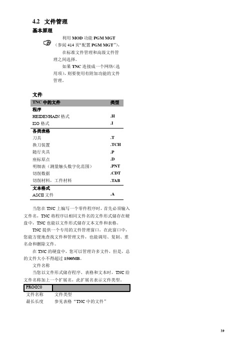
文件TNC中的文件类型程序HEIDENHAIN格式.HISO格式.I各类表格刀具.T换刀装置.TCH随行夹具.P座标原点.D明细表(测量触头数字化范围).PNT切削数据.CDT切削材料,工件材料.TAB文本格式ASCII文件.A当您在TNC上编写一个零件程序时,首先必须输入文件名,TNC将程序以相同文件名的文件形式储存在硬盘中,TNC也能以文件形式储存文本文件和表格。
TNC提供一个专用的文件管理窗口,在此窗口中,您能方便地查找文件和管理文件,也能调用、复制、重名命和删除文件。
在TNC的硬盘中,您可以管理许多文件,但是,总的文件大小不得超过1500MB。
文件名称当您以文件形式储存程序、表格和文本时,TNC给文件名称加上一个扩展名,此扩展名表示文件类型。
最长长度参见表格“TNC中的文件”数据安全我们建议定期在PC上保存最新编写的程序和文件。
您可以从HEIDENHAIN获得免费的后备程序TNCBACK。
EXE用于在PC上保存程序和文件。
您的机床制造商能提供TNCBACK。
EXE的复制件。
此外,您还需要一个软盘,用于储存机床专用数据,例如PLC程序、机床参数等等。
有关后备程序和软盘的详细资料,请和机床制造商联系。
☞保存硬盘上的全部内容可能要几个小时,因此,一个好的办法是在工作时间以外来保存(例如隔夜),或者利用平行执行功能,工作时在后台保存。
☝根据运转条件不同(例如震动负荷),当运转了三—五年之后,硬盘一般会有较高的故障率,因此,HEIDENHAIN建议三至五年之后,要对硬盘进行检查。
4.3标准文件管理说明如果您打算在一个目录下面保存全部文件,或者您已经在老的TNC控制器上已操作的很熟练,标准文件管理则是最好的方法。


气体应用大全目录一、金属有机化合物气体 (1)(一)、三甲基锡Sn(CH3)3 (1)(二)、三甲基氯硅烷SiCl(CH3)3 (1)(三)、二甲基二氯硅烷SiCl2(CH3)2 (2)(四)、甲基三氯硅烷SiCl3CH3 (3)(五)、四甲基硅烷Si(CH3)4 (3)(六)、三乙基铟In(C2H5)3 (4)(七)、三甲基铟In(CH3)3 (4)(八)、三乙基镓Ga(C2H5)3 (5)(九)、三甲基镓Ga(CH3)3 (6)(十)、三乙基三氯化二铝Al2Cl3(C2H5)3 (6)(十一)、三异丁基铝Al(i-C4H9)3 (7)(十二)、三乙基铝Al(C2H5)3 (8)(十三)、三甲基铝Al(CH3)3 (9)(十四)、三丁基硼B(C4H9)3 (11)(十五)、三丙基硼B(C3H7)3 (12)(十六)、三乙基硼B(C2H5)3 (12)(十七)、三甲基硼B(CH3)3 (13)(十八)、二乙基汞Hg(C2H5)2 (13)(十九)、二甲基汞Hg(CH3)2 (14)(二十)、二乙基镉Cd(C2H5)2 (14)(二十一)、二甲基镉Cd(CH3)2 (15)(二十二)、二乙基锌Zn(C2H5)2 (15)(二十三)、二甲基锌Zn(CH3)2 (16)(二十四)、二乙基碲Te(C2H5)2 (17)(二十五)、二甲基碲Te(CH2)2 (18)(二十六)、二乙基硒Se(C2H5)2 (18)(二十七)、三乙基锑Sb(C2H5)3 (19)(二十八)、三乙基磷P(C2H5)3 (19)(二十九)、四乙基铅Pb(C2H5)4 (20)(三十)、四甲基铅Pb(CH3)4 (22)(三十一)、溴化三-正--丁基锡SnBr(C4H9)3 (22)(三十二)、溴化三乙基锡SnBr(C2H5)3 (23)(三十三)、溴化三乙基锡SnBr(C2H5)3 (23)(三十四)、四乙基锡Sn(C2H5)4 (23)(三十五)、四甲基锡Sn(CH3)4 (24)(三十六)、三乙基锡Sn(C2H5)3 (24)二、氟化物气体 (25)(一)、三氟硅烷SiHF3 (25)(二)、二氟硅烷SiH2F2 (26)(三)、一氟硅烷SiH3F (26)(四)、六氟丙酮C3F6O或CF3COCF3 (26)(五)、羰基氟COF2或CF2O (28)(六)、1,2-二溴四氟乙烷C2Br2F4或CF2BrCBrF2 (29)(七)、溴代三氟乙烯C2BrF3或F2CCBrF (30)(八)、三氟溴甲烷CF3Br (31)(九)、二氟二溴甲烷CBr2F2 (35)(十)、1,2-二氯四氟乙烷C2C12F4或CClF2CClF2 (36)(十一)、溴代三氟乙烯C2BrF3或F2CCBrF (37)(十二)、三氟溴甲烷CF3Br (38)(十三)、二氟二溴甲烷CBr2F2 (42)(十四)、1,2-二氯四氟乙烷C2C12F4或CClF2CClF2 (44)(十五)、三氟三氯乙烷C2C13F3或CCI2FCCIF2 (45)(十六)、氯三氟乙烯C2C1F3或CF2CClF (46)(十七)、二氟四氯乙烷C2C14F2或CFCl2CFCl2 (47)(十八)、三氟氯甲烷CClF3 (48)(十九)、三氟乙烷C2H3F3或CH3CF3 (49)(二十)、1,1-二氟乙烷C2H4F2或H3CCHF2 (50)(二十一)、1,1-二氟乙烯C2H2F2 (52)(二十二)、乙基氟C2H5F (53)(二十三)、氟乙烯C2H3F或CH2CHF (54)(二十四)、三氟甲烷CHF3 (55)(二十五)、二氟甲烷CH2F2 (56)(二十六)、甲基氟CH3F (57)(二十七)、五氟化碘IF6 (58)5(二十九)、三氟化溴BrF3 (61)(三十)、五氟化氯C1F5 (62)(三十一)、三氟化氯C1F3 (63)(三十二)、六氟化钨WF6 (65)(三十三)、六氟化钼MoF6 (66)(三十四)、六氟化碲TeF6 (67)(三十五)、六氟化硫SF6 (68)(三十六)、四氟化硫SF4 (69)(三十七)、二氟化氧OF2 (70)(三十八)、五氟化砷AsF5 (71)(三十九)、三氟化砷AsF3 (71)(四十)、五氟化磷PF5 (72)(四十一)、三氟化磷PF3 (74)(四十二)、四氟肼N2F4 (75)(四十三)、三氟化氮NF3 (76)(四十四)、四氟化锗Ge4 (77)(四十五)、六氟乙硅烷Si2F6 (77)(四十六)、四氟硅烷SiF4 (78)(四十七)、全氟丁烷C4F10 (80)(四十八)、八氟丙烷C3F8 (81)(四十九)、六氟丙烯C3F6或CF3CFCF2 (82)26(五十一)、四氟乙烯C2F4 (84)(五十二)、四氟化碳CF4 (85)(五十三)、三氟化硼BF3 (87)(五十四)、氟化氢HF (89)(五十五)、氟F2 (91)(五十六)、二氟一氯一溴甲烷CF2ClBr (94)(五十七)、1,1-二氟-1-氯乙烷C2H3C1F2或CH3CF2Cl (96)(五十八)、氯二氟乙烯C2HClF2或CF2CHCl (97)(五十九)、一氯二氟甲烷CHClF2 (98)(六十)、二氯氟甲烷CHCl2F (100)(六十一)、过氯氧基氟C1O3F (101)(六十二)、硫酰氟SO2F2 (102)三、氯化物气体 (103)(一)、光气COCl2 (103)(二)、氯化氰ClCN (107)(三)、三氯硅烷SiHCl3 (109)(四)、二氯二氢硅SiH2Cl2 (112)(五)、氯丙烯C3H5Cl或CH2CHCH2Cl (114)(六)、氯乙烷C2H5Cl或CH3CH2C1 (115)(七)、1,2-二氯乙烷C2H4C12或CH2ClCH2Cl (118)(八)、氯乙烯C2H3Cl (119)23(十)、氯甲烷CH3Cl (122)(十一)、二氯甲烷CH2Cl2 (125)(十二)、五氯化锑SbCl5 (126)(十三)、三氯化锑SbCl3 (127)(十四)、三氯化砷AsCl3 (129)(十五)、三氯化磷PCl3 (130)(十六)、迭氮氯ClN3 (133)(十七)、四氯化锡SnCl4 (134)(十八)、四氯化锗GeCl4 (135)(十九)、四氯硅烷SiCl4 (136)(二十)、四氯化碳CCl4 (138)(二十一)、三氯化硼BCl3 (141)(二十二)、氯化氢HCl (143)(二十三)、氯Cl2 (148)(二十四)、三氯氢硅 (153)(二十五)、一氯一溴甲烷CH2ClBr (155)(二十六)、氧氯化磷POCl3 (155)(二十七)、亚硝酰基氯NOCl (157)(二十八)、五氯化磷PCl5 (159)四、常用标准混合气体 (160)(一)、激光混合气 (161)(二)特殊仪器仪表用混合气 (161)(三)、焊接用混合气 (162)(四)、保鲜混合气 (163)(五)、电光源用混合气 (164)(六)、医疗及生物研究混合气 (164)(七)、外延(生长)混合气 (166)(八)、参杂混合气 (166)(九)、化学气相淀积(CVD)用混合气 (167)(十)、蚀刻混合气 (167)(十一)、特殊仪器用混合气 (168)(十二)、激光混合气 (169)五、单组份气体 (170)(一)、氙Xe (170)(二)、氪气Kr (172)(三)、氩气Ar (173)(四)、氖气Ne (175)(五)、氦气He (176)(六)、氮气N2 (178)(七)、空气 (181)六、溴化物气体、碘化物气体 (182)(一)、溴乙烯C2H3Br (182)(二)、溴乙烷C2H5Br (184)3(四)、溴化氢HBr (188)(五)、溴Br2 (191)(六)、三溴化硼BBr3 (194)(七)、三溴化磷PBr3 (195)(八)、碘化氢HI (196)七、氧化物气体 (198)(一)、羰基铁C5FeO5或Fe(CO)5 (198)(二)、羰基镍Ni(CO)4 (199)(三)、羰基硫COS (200)(四)、三氧化硫SO3 (203)(五)、二氧化硫SO2 (204)(六)、一氧化二氮N2O (209)(七)、三氧化氮N2O3 (210)(八)、一氧化氮NO (212)(九)、二氧化氮NO2或N2O4 (214)(十)、二氧化碳CO2 (219)(十一)、一氧化碳CO (221)(十二)、臭氧O3 (225)(十三)、氧O2 (226)八、氢化物气体 (230)(一)、碲化氢TeH2 (230)2(三)、硫化氢H2S (234)(四)、过氧化氢H2O2 (238)(五)、锑化氢SbH3 (242)(六)、砷化氢AsH3 (243)(七)、磷化氢PH3 (247)(八)、迭氮酸HN3 (251)(九)、氨NH3 (252)(十)、四氢化锡SnH4 (256)(十一)、氢化锗GeH4 (256)(十二)、乙硅烷Si2H6 (259)(十三)、丙硅烷Si3H8 (261)(十四)、丁硅烷Si4H10 (262)(十五)、硅烷SiH4 (262)(十六)、乙硼烷B2H6 (266)(十七)、重氢D2 (270)(十八)、氢H2 (272)九、碳氢化合物气体 (277)(一)、乙醚C2H5OC2H5 (277)(二)、二乙胺(C2H5)2NH (280)(三)、甲基乙烯基醚C3H6O或CH3OCHCH2 (282)(四)、三甲胺C3H9N(CH3)3N (284)(五)、甲醚C2H6O或CH3OCH3、(CH3)2O (287)(六)、乙醇CH3CH2OH (289)(七)、氧化乙烯 (292)(八)、乙醛C2H4O或CH3CHO (295)(九)、二甲(基)胺C2H2N或(CH3)2NH (297)(十)、单乙基胺C2H7N或C2H5NH2 (300)(十一)、甲基硫醇CH4S或CH3SH (302)(十二)、四氢呋喃 (304)(十三)、二氧五环 (306)(十四)、甲醛HCHO (307)(十五)、六氢吡啶C5H11N (310)(十六)、吡啶C5H5N (311)(十七)、单甲基胺CH5N或CH3NH2 (313)(十八)、重氮甲烷CH2N2 (316)(十九)、氰化氢HCN (317)(二十)、苯C6H6 (321)(二十一)、2,2-二甲基丙烷C5H12或(CH3)4C (325)(二十二)、3-甲基-1-丁烯C5H10或(CH3)2CHCHCH2 (327)(二十三)、异丁烯C4H8或(CH3)2CCH2 (329)(二十四)、异丁烷C4H10或CH(CH3)3 (331)(二十五)、正丁烷C4H10 (332)(二十六)、环丁烷 (335)(二十七)、反-2-丁烯C4H8或CH3CHCHCH3 (336)(二十八)、顺-2-丁烯C4H8或CH3CHCHCH3 (338)(二十九)、1-丁烯C4H8或CH3CH2CHCH2 (340)(三十)、乙基乙炔C4H6或CH3CH2CCH (342)(三十一)、2-丁炔C4H6或CH3CCCH3 (344)(三十二)、1,3-丁二烯C4H6或H2CCHCHCH2 (345)(三十三)、乙烯基乙炔C4H4或CH2CHCCH (348)(三十四)、丙烷C3H8 (348)(三十五)、环丙烷 (351)(三十六)、丙烯C3H6或CH3CHCH2 (353)(三十七)、丙二烯C3H4或CH2CCH2 (356)(三十八)、甲基乙炔C2H4或CH3CCH (358)(三十九)、乙烷C2H6 (360)(四十)、乙炔C2H2 (362)(四十一)、乙烯C2H4 (366)(四十二)、甲烷CH4 (369)十、其他气体 (372)(一)、液化天然气LNG (373)(二)、液化石油气LPG (374)(三)、煤气 (378)(四)、汽油C5H12~C12H26 (379)(五)、氰C2N2或NCCN (382)(六)、二硫化碳CS2 (384)(七)、汞Hg (389)一、金属有机化合物气体(一)、三甲基锡Sn(CH3)31.别名·英文名Trimethyl tin.2.用途杀虫剂、种子的消毒剂、合成橡胶的稳定剂和阻氧化剂、木材和纺织材料的防腐剂。

简答第一章1.试述生物膜的化学组成、结构特点和分布特征。
细胞膜:细胞质膜以及包裹各种细胞器的膜性结构化学组成:膜脂(约占生物膜40%-50%):磷脂(含量最多),糖脂,胆固醇膜蛋白(约占生物膜50%):外周蛋白(20-30%),内在蛋白(70-80%)膜糖类(约占生物膜〈10%):以寡糖链形式位于质膜外结构特点:生物膜是一种有序排列的、流动的、嵌有蛋白质和附着糖链的脂质双分子层结构。
糖、脂和蛋白质在膜中分布呈不对称和流动性。
膜脂:两性分子(一侧含亲水的头部:极性头;另一侧含疏水尾部:疏水尾);可在水溶液中自动形成团粒或片状双层结构膜蛋白:可单次或多次跨膜分布特征:膜蛋白分布在脂质双层两侧表面,有的部分或全部嵌入其内部,有的横跨膜层膜糖全部分布在膜的非胞质面膜脂分布不对称性:表现为各种组分含量比例上的差异膜蛋白分布不对称:有的蛋白质对膜的一侧结合得比另一侧紧密2.试述生物膜流动镶嵌模型的主要内容。
生物膜是一种有序排列的、流动的、嵌有蛋白质和附着糖链的脂质双分子层结构。
1.脂质双分子层是由磷脂和糖脂构成的连续体2.膜脂、膜蛋白和糖类在膜中呈不对称分布3.膜脂和膜蛋白主要进行侧向扩散运动4.膜蛋白功能需要其周围的界面脂来维系5.功能上相关联的膜蛋白常形成复合体3.举例说明脂质、蛋白质和糖链在膜中分布不对称的意义。
生物膜脂质、蛋白质和糖链在质膜两侧分布的不对称性,保证了生物膜执行功能的定向性和不对称性。
膜脂:1.脂双层两侧具有不同的流动性;2.有利于膜脂本身的代谢变化;3.使镶嵌蛋白具有特定的微环境;4.有利于生物膜发挥特殊功能膜蛋白:生物膜执行定向性功能。
寡糖链:参与细胞之间的相互识别、相互作用、信息传递等多方面功能。
举例:1.多数激素的受体分布在膜外侧面(配体来源于质膜外);2.腺苷酸环化酶分布在膜内侧面(作用的底物ATP来源于细胞内);3.镶嵌在膜中的Na+-K+-ATP酶(转运的Na+,K+分别来自于胞内,胞外)4.试述膜蛋白生物合成的信号假说要点,及其特征。
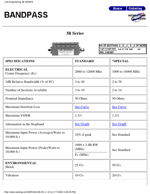
3B SeriesSPECIFICATIONS STANDARD *SPECIAL ELECTRICALCenter Frequency (Fc)2000 to 12000 Mhz 1000 to 18000 MHz 3dB Relative Bandwidth (% of FC) 3 to 20 2 to 70Number of Sections Available 3 to 10 2 to 14Nominal Impedance 50 Ohms 50 Ohms Maximum Insertion Loss See Curve See Curve Maximum VSWR 1.5/1 1.3/1Attenuation in the StopbandSee Graph See Graph Maximum Input Power (Average)(Watts to 10,000 ft.)10% if peak See StandardMaximum Input Power (Peak)(Watts to 10,000 ft.)1000 x 3 dB BW (MHz)Fc (MHz)See StandardENVIRONMENTAL Shock 25 G's 50 G's Vibration10 G's20 G'sHumidity90% relative100% relative Altitude Unlimited UnlimitedTemperature Range (Operating)-25 to + 50 degreescelsius-54 to + 100 degreescelsiusTemperature Range (Non-Operating)-54 to + 70 degreescelsius-62 to +150 degreescelsiusMECHANICALApproximate Weight in oz.0.8 x H x L0.7 x H x LMounting Provisions See below See belowSpecial Configurations Consult Factory Consult FactoryINSERTION LOSS:The Maximum Insertion Loss atcenter frequency is equal to :LF x (N + 0.5) / % 3 dB BW + 0.1Where:LF= Loss Factor, N= Number ofSections% 3dB BW:3dB BW (MHz) x 100divided byCenter Frequency (MHz)Example:A 5 section 3B with a centerfrequency of 10000 MHz and a 3dBBW of 500 MHz would have,.9 x 5.5 / 5 = 0.990.99 + 0.1 = 1.1 dBMECHANICAL SPECIFICATIONSL Dimension = N x (0.3 + 0.5 / %BW)+ 1.0 inch Approx H Dimension = 1450 / Fc(MHz) + 0.6 inch Approx.Connectors Available on 3B SeriesLark Code Type C DIM.Inches & MMLarkCodeType C DIM.Inches & MMA SMA JACK.375 & 9.5*G N JACK.736 & 18.7B SMA PLUG.507 & 12.9*H N PLUG.819 & 20.8*C TNC JACK.750 & 19.1S SPECIAL*D TNC PLUG.844 & 21.4* Not recommended for use with this SeriesThe size shown is a standard used by Lark to facilitate a low cost, easily reproducible unit. Should you require another size, please submit all of your requirements-both electrical and mechanical. This will enable Lark Engineering to quote theoptimum design for your application.STOPBAND SPECIFICATIONSThe graphs on the following pages define the normal specification limits on attenuation Lark bandpass filter series 2B, 3B, and 4B. The minimum level of attenuation in dB is shown as a "number of 3dB bandwidths from centerfrequency".Since the frequency characteristics vary for differing bandwidths, it is necessary to establish specifications for each bandwidth of filter. The different graphs represent various 3dB percentage bandwidths. Intermediate values should be interpolated. The 3dB percentage bandwidth is defined as follows:3dB Bandwidth (MHz) x 100divided byCenter Frequency (MHz)The exact relationship is as follows:1. 3dB Bandwidths From Center Frequency= Rejection Frequency (Mhz) -Center Frequency (Mhz) divided by 3dB Bandwidth (Mhz)Example:Given:2. Center Frequency = 5000 MHz Minimum 3dB Bandwidth = 500 MHzNumber of Sections = 5Find: Minimum attenuation levels at 4250 MHz and 5800 MHz.3dB BW's from Fc = 4250 - 5000 / 500 = - 1.5and 5800 - 5000 / 500 = + 1.6The answer can be read directly from the 10% graph. Using the 5 section curve at the point -1.5 (4250 MHz) we find the minimum level of attenuation is 40dB.At +1.6 (5800 MHz) the minimum level of attenuation is 50dB.For special requirements, please contact our Application EngineeringDepartment.STOPSP3.HTM元器件交易网STOPBAND SPECIFICATIONSSTOPBAND SPECIFICATIONSSTOPSP3.HTM元器件交易网STOPBAND SPECIFICATIONS。

TN系统。
TN电力系统有一点直接接地,电气设施的外露可导电部分用保护线与该点连接。
按照中性线与保护线的组合情况,TN系统有以下三种型式:TN-S系统.整个系统的中性线与保护线是分开的。
TN-C-S系统,系统中有一部分中性线与保护线是合一的。
TN-C系统,整个系统的中性线与保护线是合一的。
TT系统:TT电力系统有一个直接接地点,电气设施的外露可导电部分发接至电气上与力系统的接地点无关的接地极根据近年来,杭州经济技术开发区开发的民用建筑,低压配电较常用的接地系统为TN-S和TNCS系统,TNS系统由于自变电所至用电设备专用PE保护线,因此,相线L与中性线N 发生短路或中性线电位偏移所引起的对地电位对PE线无影响,有利于防止人体接触电压的危险,但该系统需敷设专用的PE线,且N线自变电所引出后至用电设备不可接地,因此当出现故障时N线将呈现高电位,有可能导致检修人员触电的危险,所以在建筑物进户处总开关和末级线路保护开关,需设四级或二极开关切断N线,作为检修时隔离的作用,TNC-S 系统由于变电所出线是用PEN线引出,省却了专用的PE线,且PEN线与相线L为等截面,减小了相零回路阻挠,增大了接地短路电流1d,有利于提高接地保护装置的动作可靠性,与建筑物进户处及末级线路的保护开关均不需要为分断N线设四极和二极开关,一次投资较TNS系统节省。
2.间接接触电击预防技术1)保护接地(IT系统)保护接地系统就是IT系统。
其构成如图15所示。
图中,Ll,L2,L3是相线,N是中性点,Z是配电网对地绝缘阻抗,Rp是人体电阻,RE是保护接地电阻,IE是接地电流。
所谓接地,就是将设备的某一部位经接地装置与大地紧密连接起来。
保护接地的做法是将电气设备在故障情况下可能呈现危险电压的金属部位经接地线、接地体同大地紧密地连接起来;其安全原理是把故障电压限制在安全范围以内。
IT系统的字母I表示配电网不接地或经高阻抗接地,字母T表示电气设备外壳接地。
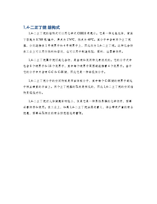
1,4-二正丁烷 结构式
1,4-二正丁烷的结构式可以用化学式C8H18来表示。
它是一种无色液体,常温下密度为0.769克/毫升,沸点为174℃,燃点为49℃。
其分子中含有两个正丁烷基,分别连接在1号碳原子和4号碳原子上,因此称为1,4-二正丁烷。
这种化合物在工业上可以用作燃料和溶剂,也可以用于制造橡胶、塑料、油墨等物质。
1,4-二正丁烷属于烷烃类化合物,是由碳和氢两种元素组成的。
它的分子式中包含8个碳原子和18个氢原子,其中每个碳原子周围都连接着4个氢原子。
由于它的分子中只含有C-C和C-H键,因此它是一种非极性分子。
1,4-二正丁烷分子的空间构型是四面体型分子,其中每个C-H键的碳原子都处于相互垂直的平面上。
两个正丁烷基的取向是相反的,因此1,4-二正丁烷的空间结构呈镜像对称。
1,4-二正丁烷对人体健康影响较小,但是它是一种易燃易爆的化学物质,需要妥善保存和使用。
在工业上,如果1,4-二正丁烷泄漏或着火,将会带来严重的安全隐患,需要采取相应的安全防范措施来管理。
ISHANDONG UNIVERSITY OF TECHNOLOGY毕业设计说明书飞秒激光深孔加工理论与系统设计学院:机械工程学院专业:机械设计制造及其自动化学生姓名:王继刚学号: 1111011178指导教师:张彦斐2015年 6 月摘要飞秒激光加工以其独特的加工优势越来越受到人们的注意,近年来飞秒激光加工技术迅猛发展。
本设计对飞秒激光深孔加工的理论和飞秒激光深孔加工系统进行了研究,主要研究内容如下:一、从飞秒激光加工原理角度出发,研究了飞秒激光加工的一般原理及其加工的优点。
首先,对飞秒激光加工的理论基础和理论模型进行了研究,理论模型采用双温方程,对其进行了研究;其次,重点研究了飞秒激光加工的一般原理;最后,总结出了飞秒激光加工深孔的优势。
二、采用有限元法对一维双温方程进行合理约化。
现行比较盛行的对双温方程的简化几乎都是采用有限差分法,其理论基本已经相当成熟,考虑到现代计算机技术的飞速发展,本论文提出采用有限元法对双温方程进行合理约化,并采用matlab进行数值模拟。
三、本设计在认真研究飞秒激光深孔加工理论的基础上,设计出了一种应用于飞秒激光深孔加工的加工平台。
该平台与现行的加工平台有所不同,可以实现X、Y、Z三个方向的大行程移动和X、Y方向的微小移动,并将二自由度微定位平台应用于其中。
关键词:飞秒激光,深孔加工,加工平台,系统设计IIAbstractFemtosecond laser machining is becoming very popular because of its unique advantages in recent years,femtosecond laser processing technology developed rapidly.This design has studiedfemtosecond laser deep hole machining theory and femtosecond laser deep hole processing system ,The main contention this dissertation are classified as follows.1. From the Angle of the femtosecond laser machining principle, the general principles of femtosecond laser machining and its processing advantages is studied.Firstly,On the basic theory of femtosecond laser machining and theoretical models are studied,the theoretical model is the double -temperature equation.Secondly,the general principles of femtosecond laser machining is mainly stly,summarized the advantage of femtosecond laser deep-hole processing.2. Using finite element methodtosimplify the one-dimensional double-temperature equation in a reasonable manner.The current relatively popular simplifying double-temperatureequation are almost using the finite difference method,and its basic theory has been quite mature.Considering the rapid development of modern computer technology,this paper presents the finite element method about the double- temperature equation in a reasonable mannerand numerical simulation with matlab.3.This design in earnest study of femtosecond laser theory on the basis of the deep hole processing, devised a application form of a second laser deep-hole processing platform. The platform are different from the existing processing platform, it can realize the X, Y, Z three directions of big trip and X, Y direction of the tiny movement, and it is applied to two degree of freedom micropositioning platform.Key words: Femtosecond laser; Thedeep-hole processing ; Processing platform; System designIII目录摘要 (I)ABSTRACT................................................................................................................ I II 目录 . (IV)第一章绪论 .............................................................................................................. - 1 -1.1课题的研究背景及其目的意义 (1)1.2现代深孔加工的方法 (2)1.2.1 现代深孔钻削技术................................................................................ - 2 -1.2.2 深孔的特种加工技术............................................................................ - 3 -1.2.3 SIED技术............................................................................................... - 4 -1.3飞秒激光打孔的优点 (5)1.4飞秒激光打孔技术在国内外的研究现状 (5)1.4.1 飞秒激光加工技术的发展.................................................................... - 5 -1.4.2 飞秒激光孔加工技术的研究现状........................................................ - 7 -1.5飞秒激光加工系统概况 (8)1.6本课题的研究内容 (10)第二章飞秒激光加工的理论基础与理论模型 .................................................... - 11 -2.1飞秒激光加工的理论基础 (11)2.1.1 飞秒激光加工金属的一般机理.......................................................... - 11 -2.1.2 飞秒激光加工的主要理论.................................................................. - 12 -2.2飞秒激光加工的理论模型 (13)2.3本章小结 (14)第三章飞秒激光与金属材料相互作用时有限元数值模拟 ................................ - 15 -3.1模型的建立 (15)3.11适用于飞秒激光的双温方程 (15)3.1.2模拟参数 (15)IV3.1.3有限元法计算 (15)3.1.4计算结果与分析 (21)3.2本章小结 (23)第四章飞秒激光深孔加工研究 ............................................................................ - 24 -4.1飞秒激光深孔零件加工工艺特点及基准选择 (24)4.1.1 飞秒激光深孔零件的加工工艺特点.................................................. - 24 -4.1.1 飞秒激光深孔零件加工的基准选择.................................................. - 24 -4.2影响深孔圆度的参数 (24)4.3影响深孔深度的参数 (26)4.4本章小结 (26)第五章飞秒激光深孔加工系统设计 .................................................................... - 28 -5.1飞秒激光器 (28)5.2飞秒激光深孔加工系统的主要组成 (30)5.2.1 偏振片.................................................................................................. - 30 -5.2.2 波片...................................................................................................... - 31 -5.2.3 衰减片.................................................................................................. - 32 -5.2.4 物镜...................................................................................................... - 33 -5.2.5 CCD图像传感器 ................................................................................. - 33 -5.3飞秒激光深孔加工平台总体设计与工作原理 (34)5.3.1 飞秒激光深孔加工平台的总体设计.................................................. - 34 -5.3.2 飞秒激光深孔加工平台的工作原理.................................................. - 36 -5.4 DELTA机构设计 (36)5.4.1 动平台的结构设计.............................................................................. - 36 -5.4.2 上、下连杆的结构设计...................................................................... - 37 -5.4.2 带轮座的结构设计.............................................................................. - 39 -5.5二自由度微定位平台设计 (40)5.6本章小结 (42)第六章结论 ............................................................................................................ - 43 -V参考文献 ................................................................................................................ - 44 -致谢 ........................................................................................................................ - 46 -VI- 1 -第一章绪论1.1课题的研究背景及其目的意义深孔加工,特别是微小深孔的加工是现代机械加工领域研究的重要内容,不论从机械装备品的发展还是从深孔加工技术的现有水平来看,深孔加工技术都还处于新兴发展阶段。

安全技术说明书页: 1/11 巴斯夫安全技术说明书按照GB/T 16483编制日期 / 本次修订: 17.12.2021版本: 4.1日期/上次修订: 25.05.2021上次版本: 4.0日期 / 首次编制: 17.09.2013产品: 特夫蓝Product: Turf Mark(30587783/SDS_GEN_CN/ZH)印刷日期 22.10.20231. 化学品及企业标识特夫蓝Turf Mark推荐用途和限制用途: 特种染料公司:巴斯夫(中国)有限公司中国上海浦东江心沙路300号邮政编码 200137电话: +86 21 20391000传真号: +86 21 20394800E-mail地址: **********************紧急联络信息:巴斯夫紧急热线中心(中国)+86 21 5861-1199巴斯夫紧急热线中心(国际):电话: +49 180 2273-112Company:BASF (China) Co., Ltd.300 Jiang Xin Sha RoadPu Dong Shanghai 200137, CHINA Telephone: +86 21 20391000Telefax number: +86 21 20394800E-mail address: ********************** Emergency information:Emergency Call Center (China):+86 21 5861-1199International emergency number: Telephone: +49 180 2273-1122. 危险性概述纯物质和混合物的分类:根据 GHS 标准,该产品不需要进行分类。
巴斯夫安全技术说明书日期 / 本次修订: 17.12.2021版本: 4.1产品: 特夫蓝Product: Turf Mark(30587783/SDS_GEN_CN/ZH)印刷日期 22.10.2023标签要素和警示性说明:防范说明:P101如需就医:请随身携带产品容器或标签。