诺瓦科技全彩LED接收卡MRV316产品使用说明书
- 格式:rtf
- 大小:5.36 MB
- 文档页数:15


西安诺瓦电子科技有限公司
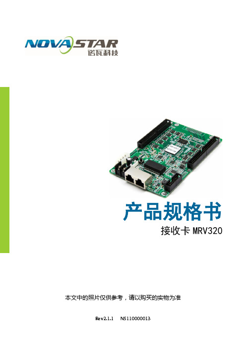
产品规格书
接收卡MRV340
概述
MRV340 是诺瓦 M3 系列的升级版本接收卡,其兼容 MRV300 所有功能。
1)单卡输出RGBR’数据16组;
2)单卡输出RGB数据20组;
3)单卡输出RGB数据24组;
4)单卡输出串行数据64组;
5)单卡带载像素为256×226;
6)支持配置文件回读;
7)支持温度监控;
8)支持网线通讯状态检测;
9)支持供电电压检测;
10)支持逐点亮色度校正;
11)支持接收卡预存画面设置。
接口定义
控制系统有 4 种工作模式,每种模式的 2 个 50P 输出不同数据,只需要用一版通用程
序和软件即可,无需定制程序;接口定义如下:
4)64 组串行数据模式
支持 64 组串行数据,定义如下:
JH1 JH2
尺寸外观说明
板卡厚度约1.6m m,总厚度(板卡厚度+正反面器件厚度)约为18.5m m。
单位:m m
技术参数
附录
串行译码电路:
第10页。


A5sCopyright © 2018 Xi’an NovaStar Tech Co., Ltd. All Rights Reserved.No part of this document may be copied, reproduced, extracted or transmitted in any form or by any means without the prior written consent of Xi’an NovaStar Tech Co., Ltd.Change HistoryChange HistoryTrademarkis a trademark of Xi’an NovaStar Tech Co., Ltd.StatementYou are welc o me to use the product of Xi’an NovaStar Tech Co., Ltd. (hereinafter referred to as NovaStar). This document is intended to help you understand and use the product. For accuracy and reliability, NovaStar may make improvements and/or changes to this document at any time and without notice. Any problem in use or any good suggestion, please contact us through ways provided in the document. We will do our utmost to solve the problems and adopt the suggestions after evaluation as soon as possible.www.novastar.tech ContentsContents 1Safety (1)1.1 Storage and Transport Safety ......................................................................................................................11.2 Installation and Use Safety ..........................................................................................................................12Overview (2)3Characteristics (3)3.1 Improvement in Display Effect .....................................................................................................................33.2 Improvement inMaintainability (3)3.3 Improvement in Hardware Reliability ...........................................................................................................43.4 Improvement in Software Reliability ............................................................................................................54Hardware Structure (6)4.1 Appearance ..................................................................................................................................................64.2 Dimensions ..................................................................................................................................................64.3 Indicator .......................................................................................................................................................74.4 Definition of the Data Interface (Top) ...........................................................................................................84.4.1 32-Group Parallel Data Interface ..............................................................................................................84.4.2 64-Group Serial Data Interface ................................................................................................................114.4.3 Reference Design for Expandable Interfaces .........................................................................................145Software Structure (16)6Typical Networking (17)7Specifications (18)A Acronyms and Abbreviations (19)B Terms (20)XI'ANNOVASTAR 1 Safety1Safety This chapter illustrates the safety of the A5s receiving card to ensure products’ storage, transport, packing and application safety. Safety description is applicable to all personnel that contact or use the products. Pay attention to following points: ●Read throughout the description. ●Save the whole description. ● Be complied with the whole description.1.1 Storage and Transport Safety●Pay attention to dust and water prevention. ●Avoid long-term direct sunlight. ●Do not place the products at the position near fire and heat. ●Do not place the products in an area containing explosive materials. ●Do not place the products in strong electromagnetic environment. ●Place the products at a stable position to prevent damage or personal injury caused by dropping. ● Save the packing box and materials which will come in handy if you ever have toship your products. For maximum protection, repack your product as it was originally packed at the factory.1.2 Installation and Use Safety ●Only trained professionals may install the products. ●Do not insert and unplug (power cord plug) when the power is on. ●Ensure the safe grounding of the device. ●Always wear an anti-static wrist band and insulating gloves. ● Do not place the products in an area having more or strong shake.NOVASTARTECHCO., LTD. ●Perform dust removing regularly. ●Do not maintain the products without authorization but contact NovaStar as soon as possible. ● Replace spare parts only with the same parts supplied by NovaStar.www.novastar.tech12 Overview2Overview A5s is a high-end receiving card developed by NovaStar, featuring small size and large loading capacity with the single card loading capacity up to 320×256 (PWM IC) pixels. A5s supports pixel level brightness and chroma calibration, which removes color difference effectively and improves display consistency of LED images. In addition, it also supports image rotation in 90° increments, creating richer images and improving visual experiences. Software and hardware designs of the A5s concern the user deployment as well as operating and maintenance scenarios, enabling easier deployment, more stable operating and more efficient maintenance. Advanced hardware design: ●Small size and thinner thickness save space for increasingly narrower cabinet space and smaller spacing between lamps. ●Use high-density connector which is resistant to dust and vibration and features high stability and high reliability. ● Assembly network transformer features simple design and improved magnetic compatibility, helping user’s products to successfully pass the EMC authentication.Useful software design: ● Support for LVDS transmission (customized function)Product Description 3 Characteristics●Support for smart module (customized function)●Support for auto module calibration●Support for Mapping function●Support for pre-stored image setting of the receiving card●Support for module Flash management●Support for monitoring of temperature, power supply voltage●Support for monitoring of Ethernet cable communication status (customizedfunction)●Support for 5-pin LCD module●Support for image rotating in 90° incrementsProduct DescriptionProduct Description 3 CharacteristicsProduct Description 4 Hardware StructureProduct Description 3 Characteristics3.4Improvement in Software ReliabilityXI'ANA5s Receiving Card Product Description4 Hardware StructureBoard thickness is not greater than 2.0mm, and the total thickness (board thickness +thickness of both front panel and back panel) is not greater than 7.5mm.Unit of the dimension chart is “mm”. Ground connection is enabled for location hole (GND).4Hardware Structure4.1AppearanceProduct images provided in this file are for reference only , and the actual products shall prevail.Models of the high-density receptacle and plug used by A5s are shown in T able 4-1 . Table 4-1 Model of high-density connector4.2 DimensionsNOVASTARTECHCO.,LTD.Product Description 4Hardware Structure4.3 Indicator The receiving card works normally, Ethernet cable connection is normal, while no video source input is available.LTD.4.4 Definition of the Data Interface (Top) 4.4.1 32-Group Parallel Data InterfaceNC 23 24 NCNote 2. RGB data groups must be used in group.Note 3. Operating indicator that meets low level is valid.Note 4. OE_RED, OE_GREEN and OE_BLUE are display enabled pins. In case thatOE_RGB are not controlled separately, OE_RED signal is applied. When PWM chip is used, GCLK signal is enabled. Note 5. RFU1–18 are the reserved extended function interfaces. Please refer to4.4.2 64- Group Serial Data Interface XI'ANNOVASTARTECHCO.,LTD.“4.4.3 Reference Design for Expandable Interfaces”.Gigabit Ethernet portTECHCO.,Note 7. Operating indicator that meets low level is valid.Note 8. OE_RED, OE_GREEN and OE_BLUE are display enabled pins. In case thatOE_RGB are not controlled separately, OE_RED is applied. While PWMchip is used, GCLK signal is enabled.Note 9. RFU1–18 are the reserved extended function interfaces. Please refer to“4.4.3 Reference Design for Expandable Interfaces ”.RFU8 and RFU10 are signal multiplexing expandable interfaces for which the interfaces of either Recommended Smart Module Interface or Recommended Module Flash Interface can be selected at a time.LTD.CO.,TECHNOVASTARXI'AN5 Software Structure5Software StructureProgram download method:Visit w ww.novastar.tec h a nd choose D ownload > F irmware . On the F irmware section, choose the desired program package to download.XI'ANNOVASTARTECHCO.,LTD.6 Typical Networking6Typical NetworkingA5s is applied to LED display synchronous system which is generally composed of the LED display, HUB board, receiving card, video controller and controller peripheral. The receiving card is connected to the display over a HUB board.Synchronous system requires connecting a c omputer to display the computer’s images and texts on the LED screen. Structure of the synchronous system is asshown in the following figure.XI'ANNOVASTARTECHCO.,LTD.XI'ANficationsA Acronyms and AbbreviationsAAcronyms and AbbreviationsEEMC Electromagnetic Compatibility FFPGA Field - P rogrammable Gate A rray LLED Light E mitting Diode MMCU Microcontroller UnitRRCFGReceiving Card ConfigurationXI'ANNOVASTARTECHCO.,LTD.B Term sBT ermsCalibration coefficient Calibration system generates a group of values for each LED lamp, includinginformation about brightness and chroma. After display calibration, the calibrationvalues of each lamp are just the calibration coefficient.Smart moduleThe smart module is composed of Flash and MCU.The Flash could store calibration coefficients and module information. MCU could communicate with the receiving card to realize monitoring over temperature, voltage and wiring communication status, as well as LED error detection. The smart module could make monitoring unit smaller, requiring no independentmonitoring card and saving cabinet space. MappingAfter the Mapping function is enabled on NovaLCT, the target cabinet will display the cabinet number and Ethernet port information, and the user could get the receiving card’s location and wiring route.Error detectionPerform status detection for each LED lamp. If the LED lamp fails, the user could notify in a timely manner upon monitoring system.XI'ANNOVASTARTECHCO.,LTD.。

V-Can视频控制软件版本编号: Rev3.1.0 文档编号NS160000266用户手册西安诺瓦电子科技有限公司版权所有 ©2018 西安诺瓦电子科技有限公司。
保留一切权利。
非经本公司书面许可,任何单位和个人不得擅自摘抄、复制本文档内容的部分或全部,并不得以任何形式传播。
商标声明是诺瓦科技的注册商标。
声明欢迎您选用西安诺瓦电子科技有限公司(以下简称诺瓦科技)的产品,如果本文档为您了解和使用产品带来帮助和便利,我们深感欣慰。
我们在编写文档时力求精确可靠,随时可能对内容进行修改或变更,恕不另行通知。
如果您在使用中遇到任何问题,或者有好的建议,请按照文档提供的联系方式联系我们。
对您在使用中遇到的问题,我们会尽力给予支持,对您提出的建议,我们衷心感谢并会尽快评估采纳。
网址: i西安诺瓦电子科技有限公司目 录1 概述 .................................................................................................................................................. 1 2 软件安装 (2)2.1 软件获取 ...................................................................................................................................................... 2 2.2 软件安装 ...................................................................................................................................................... 2 2.3 软件运行 ...................................................................................................................................................... 2 2.4 界面介绍 (3)3 功能介绍 (5)3.1 系统 ............................................................................................................................................................. 5 3.1.1 重连 .......................................................................................................................................................... 5 3.1.2 刷新 .......................................................................................................................................................... 6 3.1.3 固件升级 ................................................................................................................................................... 6 3.1.4 自测试 ...................................................................................................................................................... 7 3.1.5 恢复出厂 ................................................................................................................................................... 8 3.1.6 网络设置 ................................................................................................................................................... 8 3.1.7 语言选择 ................................................................................................................................................... 9 3.2 配置 ............................................................................................................................................................. 9 3.2.1 输入设置 . (10)3.2.1.1 输入设置 .............................................................................................................................................. 10 3.2.1.2 输入画质 ............................................................................................................................................... 11 3.2.2 输出设置 ................................................................................................................................................. 13 3.2.2.1 输出设置 .............................................................................................................................................. 13 3.2.2.2 输出画质 .............................................................................................................................................. 14 3.2.3 模式切换 ................................................................................................................................................. 15 3.2.4 拼接 ........................................................................................................................................................ 16 3.2.5 添加窗口 ................................................................................................................................................. 17 3.2.6 设置窗口属性 ......................................................................................................................................... 18 3.2.7 配置场景信息 ......................................................................................................................................... 22 3.2.8 特效 ........................................................................................................................................................ 23 3.2.8.1 切源特效 .............................................................................................................................................. 23 3.2.8.2 Take 特效 ............................................................................................................................................. 23 3.2.9 特效速度 . (24)西安诺瓦电子科技有限公司3.2.10 场景播放 ............................................................................................................................................... 24 3.2.11 同步模式 ............................................................................................................................................... 26 3.2.12 AUX ....................................................................................................................................................... 26 3.3 OSD ........................................................................................................................................................... 27 3.3.1 J6和N6的OSD 添加 ............................................................................................................................. 27 3.3.2 其他设备OSD 添加 .. (29)西安诺瓦电子科技有限公司使用手册1 概述1概述V-Can 是一款视频处理器的智能控制平台,支持J6、N6等视频处理器和VX5s 、VX6s 等二合一视频控制器。
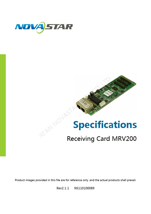
SpecificationsReceiving Card MRV200Product images provided in this file are for reference only , and the actual products shall prevail.Rev2.1.1NS110100089XI 'AN NOVA S TAR T E C H C O .,L T D.OverviewNova M3 MRV200 is the mini-version of Nova M3 receiving card. It has small size and powerful functions. It retains all the functions and features of MRV300 receiving card and is more suitable to LED curtain and die-cast aluminum cabinet.Features1) Single card outputs 16-group of RGBR 'data;2) Single card outputs 20-group of RGB data; 3) Single card outputs 64-group of serial data; 4) Single card supported resolution 256x226; 5) Configuration file readback; 6) Temperature monitoring.7) Ethernet cable communication status detection; 8) Power supply voltage detection; 9) Pixel-by-pixel brightness and chromaticity calibration. Brightnessand chromaticity calibration coefficients for each LED; 10) Pre-store picture setting; 11) Comply with EU RoHs standard; 12) Comply with EU CE-EMC standard.XI 'A N N O V A S T A R T E C H C O .,L T D.Output Interface DefinitionUnder all the three different working modes of it, three 26P interfaces can output different data, and only one common program and software is required. No customized program is necessary. Interfaces are defined as follows:1) 16-group data mode (With virtual output )Supporting 16-group of RGBR 'parallel data, defined as follows:Virtual red signal of the eighth group of data is exported as E signal of decoded signal under 32-scanning working mode.XI 'AN NOVA S TAR T E C HCO .,L T D.2) 20-group parallel data modeSupporting 20 sets of parallel data, defined as follows:I 'AN T E C HCO .,L T D.3)64-group serial data modeSupporting 64 sets of serial data, defined as follows:X I'A NN OV AS TA RT EC HC O.,L TD.Under serial mode, there are 64 data cables totally. Each cable can drive one LED bar independently.In case of horizontal LED bar, the default is, Data1 drives the first row from the top, and Data64 drives the 64th row. (front view)In case of vertical LED bar, the default is, Data1 drives the first column of from the left, and Data64 drives the 64th column. (front view).4) Special interface for light series or color screenDimensions Board thickness is not greater than 2mm, and the total thickness (board thickness + thickness of both front panel and back panel) is not greater than 18mm.Unit: mm.XI 'A N N OV A S T A R T C HCO .,L T D.AppearanceNote: Product images provided in this file are for reference only, and the actual products shall prevail.J2 definition (Connector interface of the network ports )J9 definition (Indicator light Socket ) SpecificationsI 'A N L T D.Specific Model ListTo meet the needs of different customers, Nova provides more specificmodels of the products, including standard products in stock. Othermodels need to be customized.AppendixSerial data decoding circuit:X I'A NN OV AS TA RT EC HC O.,L T。
接收卡规格书产品版本:V1.0.0文档编号:NS120000328接收卡TR100规格书www.novastar-l 更新记录V1.0.0i接收卡TR100规格书www.novastar-l ed.c n目录1概述 (1)2产品特性 (2)2.1提升显示效果 (2)2.2提升可维护性 (2)2.3提升硬件可靠性 (3)2.4提升软件可靠性 (3)3接口定义 (4)3.1 32组并行数据接口 (4)3.2扩展功能参考设计 (7)4外观 (8)5尺寸 (9)6产品规格 (10)接收卡TR100规格书www.novastar-l ed.c n1概述TR100是诺瓦科技推出的新一代接收卡,单卡带载384×384像素。
TR100支持1.0/2.3(S AA)同轴接口,使系统的连接和数据传输更加可靠。
支持SerDes技术,具有低延迟特性。
同时,T R100支持18B it+灰度输出,有效处理LED显示屏因亮度降低带来的灰度损失问题,使图像更细腻。
接收卡TR100规格书规格书备注2.RGB 数据组必须成组使用。
备注3.运行指示灯为低电平有效。
备注4.OE_RED、OE_GREEN、OE_BLUE 为显示使能引脚。
OE_RGB 不分开控制时,使用OE_RED。
当使用PWM 芯片时,为GCLK 信号。
备注5.RFU1~18 是预留扩展功能接口,详细信息请参见“3.2 扩展功能参考设计”。
规格书www.novastar-l ed.c n4外观本文中的产品照片仅供参考,实际出厂产品安装散热片,请以实际购买到的产品为准。
TR100使用的高密度接插件的母座(R eceptacle)型号如表4-1所示。
公座(P LUG)型号可以根据实际需求选择。
4-1规格书www.novastar-l ed.c n5尺寸(单位:m m)。

Receiving CardMRV328Document Version:V1.0.0Document Number: NS110100409Product Description XI 'AN N O VA S T AR T E C H CO .,LT D.Copyright © 2018 Xi’an Nov aStar Tech Co., Ltd. All Rights Reserved.No part of this document may be copied, reproduced, extracted or transmitted in any form or by any means without the prior written consent of Xi’an NovaStar Tech Co., Ltd.Trademarkis a registered trademark of Xi’an NovaStar Tech Co., Ltd.StatementYou are welcome to use the product of Xi’an NovaStar Tech Co., Ltd. (hereinafter referred to as NovaStar). This document is intended to help you understand and use the product. For accuracy and reliability, NovaStar may make improvements and/or changes to this document at any time and without notice. Any problem in use or any good suggestion, please contact us through ways provided in the document. We will do our utmost to solve the problems and adopt the suggestions after evaluation as soon as possible.X I'A NN OV AS TA RT EC HC O.,L TD.Product Description Change HistoryChange HistoryX I'A NN OV AS TA RT EC HC O.,L TProduct Description ContentsContentsChange History (ii)1 Safety (1)2 Overview (2)3 Features (3)4 Hardware Structure (4)4.1 Appearance (4)4.2 Dimensions (5)4.3 Indicators (5)4.4 Definition of Data Interface (6)5 Software Structure (7)6 Typical Networking (8)7 Specifications (10)X I'A NN OV AS TA RT EC HC O.,L TD.Product Description1 Safety1SafetyThis chapter illustrates safety of the MRV328 receiving card to ensure the produc t’s storage, transport, installation and use safety. Safety instructions are applicable to all personnel who contact or use the product. First of all, pay attention to following points.● Read through the instructions. ● Retain all instructions. ●Comply with all instructions.Storage and Transport Safety● Pay attention to dust and water prevention. ● Avoid long-term direct sunlight.● Do not place the product at a position near fire and heat.● Do not place the product in an area containing explosive materials. ● Do not place the product in a strong electromagnetic environment. ● Place the product at a stable position to prevent damage or personal injury caused by dropping.●Save the packing box and materials which will come in handy if you ever have to store and ship the product. For maximum protection during storage and shipping, repack the product as it was originally packed at the factory.Installation and Use Safety● Only trained professionals may install the product.● Plugging and unplugging operations are prohibited when the power is on. ● Ensure safe grounding of the product.● Always wear a wrist band and insulating gloves.● Do not place the product in an area having frequent or strong shake. ● Perform dust removing regularly.● Contact NovaStar for maintenance at any time, rather than have the productdisassembled and maintained by non-professionals without authorization. ●Replace faulty parts only with the spare parts supplied by NovaStar.XI 'AN NOVA S T AR T E C H CO .,LT D.2OverviewThe MRV328 is a new receiving card developed by NovaStar. A single MRV328 loads up to 256x256 pixels.The MRV328 supports pixel level brightness and chroma calibration, which effectively removes color difference, greatly improves display consistency of LED images, and presents finer displays to users.Software and hardware designs of the MRV328 have fully concerned users'deployment, operating and maintenance scenarios, enabling easier deployment, more stable operating and more efficient maintenance.Hardware design:● Integrates 8 standard HUB75 connectors, which makes the HUB board unnecessary.●Adopts the Gigabit Ethernet port, which can connect to the PC.Software design:● Supports pixel level brightness and chroma calibration. ● Supports setting of images pre-stored in the receiving card. ● Supports status detection of temperature, voltage, Ethernet cable communication and video source signals. ●Supports the 5-pin LCD module.XI 'AN NOVA S T AR T E C H CO .,LT D.3FeaturesXI 'A.4Hardware Structure4.1 AppearanceProduct images provided in this file are for reference only, and the actual products shall prevail.XI 'AN NOVA S T AR T E C H CO .,LT D.4.2 DimensionsThe board thickness is not greater than 2.0 mm, and the total thickness (board thickness + thickness of components on front and rear panels) is not greater than 17.0 mm.The unit of dimension chart is “mm”. T he location holes are connected to signal grounds (GND).4.3 IndicatorsXI 'A S T AR T E C H CO .,LT D.4.4 Definition of Data InterfaceX I'A RT EC HC O.,L TD.Product Description 5 Software Structure5 Software StructureMethod of downloading the firmware upgrade package:Visit www.novastar.tech and choose Download > Firmware. On the Firmwaresection, choose the desired program package to download.X I'A NN OV AS TA RT EC HC O.,L TD.6 Typical Networking The MRV328 is applied to the LED display synchronous system which is generally composed of the LED display, receiving card, LED display controller (optional) and controller peripherals. The receiving card is connected to the LED display over HUB connectors.The synchronous system requires connecting a computer to display the computer’s images and texts on the LED display. The synchronous system's structure is shownin the following figure.Figure 6-1 Sending card modeX I'A NN OV AS TA RT EC HC O.,L TD.Figure 6-2 No sending card modeX I'A NN OV AS TA RT EC HC O.,L TD.Product Description 7 Specifications7 SpecificationsX I'A N.。
MRV316Receiving CardDocument Version:V1.0.0Document Number: NS110100375Product Description XI 'AN N O VA S T AR T E C H CO .,LT D.Copyright © 2017 Xi’an Nov aStar Tech Co., Ltd. All Rights Reserved.No part of this document may be copied, reproduced, extracted or transmitted in any form or by any means without the prior written consent of Xi’an NovaStar Tech Co., Ltd.Trademarkis a registered trademark of Xi’an NovaStar Tech Co., Ltd.StatementYou are welcome to use the product of Xi’an NovaStar Tech Co., Ltd. (hereinafter referred to as NovaStar). This document is intended to help you understand and use the product. For accuracy and reliability, NovaStar may make improvements and/or changes to this document at any time and without notice. Any problem in use or any good suggestion, please contact us through ways provided in the document. We will do our utmost to solve the problems and adopt the suggestions after evaluation as soon as possible.X I'A NN OV AS TA RT EC HC O.,L TD.Product Description Change HistoryChange HistoryX I'A NN OV AS TA RT EC HC O.,L TProduct Description ContentsContentsChange History (ii)1 Safety (1)2 Overview (2)3 Features (3)4 Hardware (4)4.1 Appearance (4)4.2 Dimensions (5)4.3 Indicators (5)4.4 Definition of Data Interface (6)5 Software Structure (8)6 Typical Networking (9)7 Specifications (11)X I'A NN OV AS TA RT EC HC O.,L TD.Product Description1 Safety1SafetyThis chapter illustrates safety of the MRV316 receiving card to ensure the product’s storage, transport, installation and use safety. Safety instructions are applicable to all personnel who contact or use the product. First of all, pay attention to following points.● Read through the instructions. ● Retain all instructions. ●Comply with all instructions.Storage and Transport Safety● Pay attention to dust and water prevention. ● Avoid long-term direct sunlight.● Do not place the product at a position near fire and heat.● Do not place the product in an area containing explosive materials. ● Do not place the product in a strong electromagnetic environment. ● Place the product at a stable position to prevent damage or personal injury caused by dropping.●Save the packing box and materials which will come in handy if you ever have to store and ship the product. For maximum protection during storage and shipping, repack the product as it was originally packed at the factory.Installation and Use Safety● Only trained professionals may install the product.● Plugging and unplugging operations are prohibited when the power is on. ● Ensure safe grounding of the product.● Always wear a wrist band and insulating gloves.● Do not place the product in an area having frequent or strong shake. ● Perform dust removing regularly.● Contact NovaStar for maintenance at any time, rather than have the productdisassembled and maintained by non-professionals without authorization. ●Replace faulty parts only with the spare parts supplied by NovaStar.XI 'AN NOVA S T AR T E C H CO .,LT D.2OverviewThe MRV316 is a new receiving card developed by NovaStar. A single MRV316 loads up to 512x256 pixels.The MRV316 supports pixel level brightness and chroma calibration, which effectively removes color difference, greatly improves display consistency of LED images, and presents finer displays to users.Software and hardware designs of the MRV316 have fully concerned users'deployment, operating and maintenance scenarios, enabling easier deployment, more stable operating and more efficient maintenance.Hardware design:● Integrates 16 standard HUB75 connectors, which makes the HUB board unnecessary.●Adopts the Gigabit Ethernet port, which can connect to the PC.Software design:● Supports pixel level brightness and chroma calibration. ● Supports setting of images pre-stored in the receiving card. ● Supports status detection of temperature, voltage, Ethernet cable communication and video source signals. ●Supports the 5-pin LCD module.XI 'AN NOVA S T AR T E C H CO .,LT D.3FeaturesXI 'A.4Hardware4.1 AppearanceProduct images provided in this file are for reference only, and the actual products shall prevail.XI 'AN NOVA S T AR T E C H CO .,LT D.4.2 DimensionsThe board thickness is not greater than 2.0 mm, and the total thickness (board thickness + thickness of components on front and rear panels) is not greater than 17.5 mm.The u nit of dimension chart is “mm”. The location holes are connected to signal grounds (GND).4.3 IndicatorsXI 'VA S T AR T E C H CO .,LT D.4.4 Definition of Data InterfaceXI 'AN NOVA S T AR T E C H CO .,LT D.Product Description 4 HardwareX I'A NN OV AS TA RT EC HC O.,L TD.Product Description 5 Software Structure5 Software StructureFirmware in the delivery MRV316 includes MCU program and FPGA program.Program download method:Visit and change the user interface language to English at thetop right. Then, on the displayed Products&Downloads page, click the targetreceiving card in the Receiving Card section to enter its detail introduction page. Atlast, click Downloads to enter the download list and download the required programpackages.X I'A NN OV AS TA RT EC HC O.,L TD.6 Typical Networking The MRV316 is applied to the LED display synchronous system which is generally composed of the LED display, receiving card, LED display controller and controller peripherals. The receiving card is connected to the LED display over HUB connectors.The synchronous system requires connecting a computer to display the computer’s images and texts on the LED display. The synchronous system's structure is shownin the following figure.Figure 6-1 Sending card modeX I'A NN OV AS TA RT EC HC O.,L TD.Figure 6-2 No sending card modeX I'A NN OV AS TA RT EC HC O.,L TD.Product Description 7 Specifications7 SpecificationsX I'A.。


X3C接收卡规格书产品版本:V1.0.1文档编号:NS110000348版权所有© 西安诺瓦电子科技有限公司2017。
保留一切权利。
非经本公司书面许可,任何单位和个人不得擅自摘抄、复制本文档内容的部分或全部,并不得以任何形式传播。
商标声明是诺瓦科技的注册商标。
声明欢迎您选用西安诺瓦电子科技有限公司(以下简称诺瓦科技)的产品,如果本文档为您了解和使用产品带来帮助和便利,我们深感欣慰。
我们在编写文档时力求精确可靠,随时可能对内容进行修改或变更,恕不另行通知。
如果您在使用中遇到任何问题,或者有好的建议,请按照文档提供的联系方式联系我们。
对您在使用中遇到的问题,我们会尽力给予支持,对您提出的建议,我们衷心感谢并会尽快评估采纳。
更新记录目录更新记录 (ii)目录 (iii)1概述 (1)2功能特性 (2)3外观说明 (3)4尺寸图 (4)5引脚定义 (5)6规格参数 (7)规格书1概述1概述X3C是一款小尺寸全功能接收卡。
采用邮票孔接口,可以当做一个集成芯片一样焊接到转接板上。
X3C单卡最大可带载256×226像素,最多可扩展至16组并行数据,支持亮色度校正、电压温度检测等功能。
规格书2功能特性2功能特性●单卡支持256×226像素点。
●单卡支持8组RGB信号并行输出,通过D扩展可扩展为16组并行数据。
1~1/扫之间的任意扫描类型,支持595等串行译码扫描。
●支持32●支持常规芯片、P WM芯片等所有主流LED驱动芯片。
●支持高灰阶高刷新率。
●支持逐点亮色度校正。
●支持配置文件回读。
●支持网线通讯状态检测。
●支持接收卡预存画面设置。
●支持电压、温度检测。
●符合欧盟CE-EMC标准。
规格书3外观说明3外观说明本文中的产品照片仅供参考,请以实际购买到的产品为准。
规格书4尺寸图4尺寸图单位:m m 板卡厚度不大于2.0m m,正面器件厚度不大于3.5m m。
接收卡X3C规格书 5 引脚定义接收卡X3C规格书6规格参数6规格参数w 7。

2.1. 播放方案的组成播放方案对应保存为后缀plym的文件,由多个常规时段组成,此外,也可包含一个或多个插播时段。
常规时段和插播时段均由一个或多个节目页组成,每个节目页又由一个或多个窗口组成。
窗口可分为通用窗口、时钟窗口、走马灯窗口、计时窗、天气预报窗和视频设备窗。
通用窗口可添加一个或多个不同种类的媒体。
播放方案的组成如下图示例。
图2-1 播放方案组成示例常规时段可指定播放日期、一周有效播放天数、一天内有效播放时段的播放段。
例如:常规播放段“段1”,从2012/6/23到2012/6/30,星期一、三、五,每天8:00至12:00播放,如下图。
图2-2常规播放段“段1”定时插播段在指定日期范围内的有效天内,指定时间点开始播放指定次数或时长的播放段;例如:定时插播段“插播段2”,从2012/6/23到2012/6/30,星期一、三、五,每天8:30开始播放10分钟,如下图所示。
图2-3 定时插播段“插播段2”周期插播段在指定的日期范围、指定的有效天内、指定的时间段内,每隔一定时间播放指定次数或时长的播放段;例如:周期插播段“插播段3”,从2012/6/23到2012/6/30,星期一、三、五,12:00至18:00,每隔30分钟播放1次,如下图所示。
✧节目页计算机显示器屏幕上映射到LED显示屏的区域,用以实现可视的媒体数据(如视频、图像、字幕等)在LED显示屏上的显示播放。
可划分为多个显示区域,每个显示区域对应一个窗口。
●全局节目页:时段播放过程中,一直播放的节目页,可包含多个窗口。
全局节目页的播放窗口在播放时位于其它常规节目页的窗口前面。
在实际应用中,如果需要使用多种窗口布局的常规节目页,但又希望在固定位置一直显示时钟、天气预报、走马灯等媒体,可将该媒体编辑到全局节目页中;●常规节目页:常规节目页可包含多个窗口,每个常规节目页可有不同的窗口布局。
同一个播放时段可包含多个常规节目页。
多个常规节目页按从上到下的方式循环播放。

诺瓦科技LED联网播放器快速使用指南Taurus SeriesMultimedia PlayersQuick S tart Guide Document V ersion:V1.3.2Document Number:NS120100369Copyright ? 2018 Xi’an NovaStar Tech Co., Ltd. All Rights Reserved.No part of this document may be copied, reproduced, extracted or transmitted in any form or by any means without the prior written consent of Xi’an NovaStar Tech Co., Ltd.Trademarkis a trademark of Xi’an NovaStar Tech Co., Ltd.Statementwww.novastar.techi aurus Series Multimedia Players Quick Start Guide Table of ContentsTable of ContentsYou are welcome to use the product of Xi’an NovaStar Tech Co., Ltd. (hereinafter referred to as NovaStar). This document is intended to help you understand and use the product. For accuracy and reliability, NovaStar may make improvements and/or changes to this document at any time and without notice. If you experience any problems in use or have any suggestions, please contact us via contact info given in document. We will do our best to solve any issues, as well as evaluate and implement any suggestions.TTable ofContents ........................................................... .. (ii1)Overview (1)1.1 Scenario (1)1.2 Procedures (1)2 Preparation (2)2.1 Getting and Installing Software (2)2.2 Getting Required Account Information (3)3 Taurus Connections (4)3.1 Connecting via Ethernet Cable (4)3.2 Connecting via Local Area Network (LAN) (4)3.3 Connecting via Wi-Fi (5)3.3.1 Wi-Fi AP Mode .................................................................................................................. ........................53.3.2 Wi-Fi Sta Mode (6)3.3.3 Wi-Fi AP+Sta Mode (6)4 Receiving Card Parameter Configuration (8)4.1 Loading Configuration File or Configuring the Parameters Manually Through NovaLCT (8)4.2 Loading the Configuration File Through ViPlex Handy (9)5 Screen Configuration (10)6 General Operations (11)6.1 Taurus Login with ViPlex Handy (Android and iOS) (11)6.2 Taurus Login with ViPlex Express (Windows) (11)7 Caution (13)www.novastar.tech ii1 Overview 1.1 Scenario1.2 ProceduresThis document introduces a quick way to use Taurus series multimedia players andprovides instructions for the first-timer.www.novastar.tech2 Preparation2 PreparationTaurus Series Multimedia PlayersQuick Start Guidewww.novastar.tech2 Preparation3 Taurus Connections3 Taurus Connections 3.1 Connecting via Ethernet Cablewww.novastar.tech 3Taurus Series Multimedia PlayersQuick Start GuideNetwork DiagramConfiguration Users can access the Taurus directly when it is connected via the Ethernet cable.ViPlex Handy:Step 1 Refer to 6.1 Taurus Login with ViPlex Handy (Android and iOS ) to log in to the Taurus.Step 2 Click the screen name to enter the Screen management page.Step 3 Choose Network Settings > W ired Network Setting .Step 4 Turn off DHCP and set static IP address for the Taurus.ViPlex Express:Step 1 Refer to 6.2 Taurus Login with ViPlex Express (Windows ) to log in to the Taurus.Step 2 At the top right, click and select DHCP Service .Taurus Series Multimedia PlayersQuick Start GuideStep 3 Enable DHCP service to automatically assign an IP address to the Taurus.3.2 Connecting via Local Area Network (LAN)Network DiagramUsers can access the Taurus through LAN when it is connected via LAN. www.novastar.techConfigurationNo need for configuration.3.3 Connecting via Wi-FiThe Taurus series products have dual Wi-Fi function which can provide Wi-Fi hotspotas well as serve as Wi-Fi Station at the same time. The Wi-Fi working frequencyrange is 2400 MHz to 2483.5MHz.Users can access the Taurus directly when it is connected via Wi-Fi AP .3.3.1 Wi-Fi AP ModeNetwork DiagramConfigurationNo need for configuration. Please connect the Wi-Fi AP of the Taurus. SSID is “AP +last 8 digits of the SN”, for example, “AP10000033”. The default password is“12345678”.3.3.2 Wi-Fi Sta ModeNetwork DiagramUsers can access T aurus through external router when it is connected via Wi-Fi Sta.ConfigurationStep 1Refer to 6 General Operations to log in to the Taurus. Step 2 Turn on Wi-Fi Sta mode. Click the Wi-Fi name of the external router and then enter the password of the Wi-Fi.●ViPlex Handy: Select N etwork Settings > W i-Fi Setting in the S creen management page. ● ViPlex Express: Select S creen Control > N etwork configuration .3.3.3 Wi-Fi AP+Sta ModeBy using Wi-Fi AP+Sta connection, users can directly access the Taurus or accessthe Internet through bridging connection.Network DiagramConfigurationStep 1 Refer to 6 General Operations to log in to the Taurus.Step 2 Turn on Wi-Fi Sta mode. Click the Wi-Fi name of the external router and then enterthe password of the Wi-Fi.●ViPlex Handy: Select Network Settings > Wi-Fi Setting in the Screen management page. ● ViPlex Express: Select Screen Control > Network configuration .Related Information●●The Taurus can be connected to the Internet through following two ways. The priorityorder of the two ways is from high to low.Wired networkWi-Fi StaQuick Start Guide4Receiving Card Parameter Configuration 4Receiving Card Parameter ConfigurationTaurus Series Multimedia PlayersQuick Start GuideStep 5 ClickStep 6 Confirm whether the local PC has the required receiving card configuration file.www.novastar.tech4 Receiving Card Parameter Configuration●Yes. Please perform Load Configuration File . ● No. Please perform Manual Configuration .If receiving card parameters are already configured, please skip this chapter andperform the operations in 5 Screen Configuration . Loading Configuration File or Configuring the4.1 Parameters Manually Through NovaLCTStep 1 Open NovaLCT and choose User > Media Player Login . The system automatically searches the multimedia players in the same networksegment and then displays them in a specified sorting order.Step 2Click the terminal name in the terminal list. Step 3Click Connect System . Step 4Enter user name and password for logging in the terminal, and click OK . The default user na me is “ a dmin ” , and the default password is “ 123456 ”. on the main interface, and the Screen Configuration window pops up as shown in Figure 4-1 .Figure 4-1 The Screen Configuration windowTaurus Series Multimedia PlayersQuick Start GuideLoading Configuration FileStep 1 Select Load Configuration File. Click Browse to choose a configuration file from the local PC.Step 2 Click Next to load the configuration file.Manual ConfigurationStep 1 Select Configure Screen and click Next.Step 2 Configure receiving card parameters based on actual conditions.Step 3 Click Send to Receiving Card.Step 4 Adjust parameters until the screen displays normally and then click Save.Step 5 (Optional) Click Save System Configuration File to back up the receiving cardconfiguration file to the local PC.4.2 Loading the Configuration File Through ViPlex HandyStep 1 Save the receiving card configuration file to mobile phone.Step 2 Refer to 6.1 Taurus Login with ViPlex Handy (Android and iOS) to log in to the Taurus.Step 3 Click screen name to enter the Screen management page.Step 4 Select Screen Settings > RV Card Configuration to enter the RV CardConfiguration page.Step 5 Select the receiving card configuration file and click Send.5 Screen Configuration5 Screen ConfigurationStep 1 Refer to 6.1 Taurus Login with ViPlex Handy (Android and iOS) to log in to the Taurus.Step 2 Click screen name to enter the Screen management page.Taurus Series Multimedia PlayersQuick Start GuideStep 4 Configure screen information based on actual conditions and click OK. www.novastar.tech6 General Operations6 General OperationsTaurus series products feature the Wi-Fi AP function which is taken as the example bythis chapter to introduce T aurus Login methods.6.1 Taurus Login with ViPlex Handy (Android and iOS)Before You Begin●Acquire the SSID and password of Wi-Fi AP of Taurus series products. SSIDis default to be composed of AP and the last 8 numbers of SN, and thepassword is default as “12345678”.●Acquire the login password of user “admin” of which the default password is“123456”.Operating ProceduresViPlex Handy can connect numerous Taurus series products.Step 1 Connect Wi-Fi AP of the Taurus series products.Step 2 Start ViPlex Handy.System can automatically detect the Taurus series products and refresh Screen list.Users can also slide down Screen list to manually refresh the list.●: denotes that Taurus is online and you can log into it.●: denotes that Taurus is offline and you cannot log into it.●: denotes that Taurus login is successful.Step 3 Click Connect next to the screen name.Step 4 Enter the user name and password and click Login.6.2 Taurus Login with ViPlex Express (Windows) Before You Begin● Acquire the SSID and password of Wi-Fi AP of Taurus series products. SSID isdefault to be composed of AP and the last 8 numbers of SN, and the password is default as “12345678”.www.novastar.tech6 General Operations● Acquire the login password of user “admin” of which the default password is“123456”.Operating ProceduresViPlex Express can connect numerous Taurus series products.Step 1 Connect Wi-Fi AP of the Taurus series products.Step 2 Start the ViPlex Express.Step 3 Click Refresh and the screen list will be displayed on the page.●●●: denotes that Taurus is online and you can log into it.: denotes that Taurus is offline and you cannot log into it.: denotes that Taurus login is successful.After the Taurus is found by ViPlex Express, the ViPlex express will try to log into to the Taurus with the default account or the account used for last login.Step 4 Taurus login is successful or not.Yes.appears and no further operation is required. No. appears and then perform Step 5 .Step 5Click Connect o n the right of the screen information. Step 6 Enter the username and password, and click OK .。

产品规格书
接收卡 MRV220-1
本文中的照片仅供参考,请以购买的实物为准
Rev2.1.4 NS110000246
功能特性
MRV220-1是诺瓦M3系列28组数据小接收卡。
具有以下特性:
1)单卡输出RGB数据24组;
2)单卡输出RGB数据28组;
3)单卡输出串行数据64组;
4)单卡带载像素为256×226;
5)支持配置文件回读;
6)支持温度监控;
7)支持网线通讯状态检测;
8)支持供电电压检测;
9)支持逐点亮色度校正;
10)符合欧盟RoHs标准;
11)符合欧盟CE-EMC CLass A标准。
接口定义
控制系统有2种工作模式,每种模式的2个60P输出不同数据,每个60P还可
以分成2个30P,接口定义如下:
1)24组并行数据模式
支持24组RGB并行数据,定义如下:
技术参数
附录
串行译码电路:。
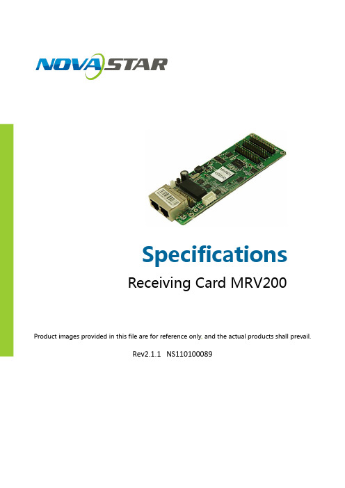
Product images provided in this file are for reference only , and the actual products shall prevail.Rev2.1.1 NS110100089SpecificationsReceiving Card MRV200OverviewNova M3 MRV200 is the mini-version of Nova M3 receiving card. It hassmall size and powerful functions. It retains all the functions andfeatures of MRV300 receiving card and is more suitable to LED curtainand die-cast aluminum cabinet.Features1)Single card outputs 16-group of RGBR 'data;2)Single card outputs 20-group of RGB data;3)Single card outputs 64-group of serial data;4)Single card supported resolution 256x226;5)Configuration file readback;6)Temperature monitoring.7)Ethernet cable communication status detection;8)Power supply voltage detection;9)Pixel-by-pixel brightness and chromaticity calibration. Brightnessand chromaticity calibration coefficients for each LED;10)Pre-store picture setting; 11)Comply with EU RoHs standard;12)Comply with EU CE-EMC standard.Output Interface DefinitionUnder all the three different working modes of it, three 26P interfaces ca n o u t p u t d i f f erent data, and only one common program and software is required. No customized program is necessary. Interfaces are defined as follows:1) 16- g roup data mode ( W ith virtual output )Support i ng 16-group of RGBR 'parallel data, defined as follows:Virtual red signal of the eighth group of data is exported as E signal of decoded signal under32-scanning working mode.group serial data B17 14 G18 16 R19 18 B19 20 G20 22 NC 24 GND 26modeUnder serial mode, there are 64 data cables totally. Each cable can drive one LED bar independently.In case of horizontal LED bar, the default is, Data1 drives the first row from the top, and Data64 drives the 64th row. (front view)Inof verticalbar, theis,drivesthe first column of from the left, and Data64 drives the 64th column.(front view).4)Special interface for light series or color screenUnit: mm.Specific Model ListTo meet the needs of different customers, Nova provides more specificmodels of the products, including standard products in stock. Othermodels need to be customized.AppendixSerial data decoding circuit : Page 10。
版权所有© 西安诺瓦电子科技有限公司2018。
保留一切权利。
非经本公司书面许可,任何单位和个人不得擅自摘抄、复制本文档内容的部分或全部,并不得以任何形式传播。
商标声明是诺瓦科技的注册商标。
声明欢迎您选用西安诺瓦电子科技有限公司(以下简称诺瓦科技)的产品,如果本文档为您了解和使用产品带来帮助和便利,我们深感欣慰。
我们在编写文档时力求精确可靠,随时可能对内容进行修改或变更,恕不另行通知。
如果您在使用中遇到任何问题,或者有好的建议,请按照文档提供的联系方式联系我们。
对您在使用中遇到的问题,我们会尽力给予支持,对您提出的建议,我们衷心感谢并会尽快评估采纳。
更新记录目录1安全说明 (1)1.1存储和运输安全 (1)1.2安装和使用安全 (1)2概述 (2)3产品特性 (4)3.1提升显示效果 (4)3.2提升可维护性 (5)3.3提升硬件可靠性 (5)3.4提升软件可靠性 (6)4硬件结构 (7)4.1外观 (7)4.2尺寸图 (7)4.3指示灯 (8)4.4数据接口定义(T op) (9)4.4.132组并行数据接口 (9)4.4.264组串行数据接口 (12)4.4.3扩展功能参考设计 (15)5软件结构 (16)6典型组网 (17)7产品规格 (18)A缩略语 (19)B术语 (20)产品说明书1安全说明1安全说明本章介绍A10s接收卡的安全说明,目的是保证产品的存储、运输、安装和使用安全。
安全说明适用于所有接触和使用产品的人员。
首先请注意以下几点:●请阅读所有说明。
●请保留所有说明。
●请遵循所有说明。
1.1存储和运输安全●请注意防尘防水。
●请避免阳光长时间直射。
●请勿靠近热源和火源。
●请勿放置在易爆气体环境中。
●请勿放置在强电磁环境中。
●请将产品放在稳固的位置,以防坠落造成产品损坏或人身伤害。
●请保存包装箱和包装材料。
存储和运输产品时可以使用。
为了最大程度地保护设备,请将产品按照出厂时的原始包装重新包好。
产品规格书
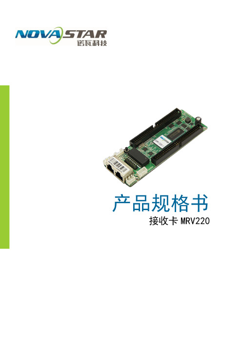
接收卡 MRV220
功能特性
M
R V 220 是诺
瓦
M
3
系列 28 组数据小接收卡。
具有以下特性:
1) 单卡输出 RGB 数据 24 组; 2) 单卡输出 RGB 数据 28 组; 3) 单卡输出串行数据 64 组; 4) 单卡带载像素为 256 × 226 ; 5) 支持配置文件回读; 6) 支持温度监控;
7) 支持网线通讯状态检测; 8) 支持供电电压检测; 9) 支持逐点亮色度校正; 10) 符合欧盟 RoHs 标准; 控制系统有 2 种工作模式 , 每种模式的 2 个 60 P 输出不同数据,每个 P 60 还可 以分成 2 个 30 P ,接口定义如下 : 1) 24 组并行数据模式 支持 24 组 RGB 并行数据, 定义如下:
11)符合欧盟 CE-EMC CLass A 标准。
接口定义
支持 28 组 RGB 并行数据,8 扫以上需要串行译码(串行译码电路见附录),定义如下:
单位:mm
附录
串行译码电路:。
MRV316
接收卡
版本 编号: V1.0.0 文档编号 :
NS 110000374
产品说明书
版权所有©2017西安诺瓦电子科技有限公司。
保留一切权利。
非经本公司书面许可,任何单位和个人不得擅自摘抄、复制本文档内容的部分或全部,并不得以任何形式传播。
商标声明
是诺瓦科技的注册商标。
声明
欢迎您选用西安诺瓦电子科技有限公司(以下简称诺瓦科技)的产品,如果本文档为您了解和使用产品带来帮助和便利,我们深感欣慰。
我们在编写文档时力求精确可靠,随时可能对内容进行修改或变更,恕不另行通知。
如果您在使用中遇到任何问题,或者有好的建议,请按照文档提供的联系方式联系我们。
对您在使用中遇到的问题,我们会尽力给予支持,对您提出的建议,我们衷心感谢并会尽快评估采纳。
产品说明书更新记录
更新记录
产品说明书目录
目录
更新记录 (ii)
1安全说明 (1)
2概述 (2)
3产品特性 (3)
4硬件结构 (4)
4.1外观 (4)
4.2尺寸图 (5)
4.3指示灯说明 (5)
4.4数据接口定义 (6)
5软件结构 (7)
6典型组网 (8)
7产品规格 (10)
产品说明书1安全说明
1安全说明本章介绍接收卡MRV316的安全说明,目的是保证产品的存储、运输、安装和使用安
全。
安全说明适用于所有接触和使用产品的人员。
首先请注意以下几点:
●请阅读所有说明。
●请保留所有说明。
●请遵循所有说明。
存储和运输安全
●请注意防尘防水。
●请避免阳光长时间直射。
●请勿靠近热源和火源。
●请勿放置在易爆气体环境中。
●请勿放置在强电磁环境中。
●请将产品放在稳固的位置,以防坠落造成产品损坏或人身伤害。
●请保存包装箱和包装材料。
存储和运输产品时可以使用。
为了最大程度地保护设
备,请将产品按照出厂时的原始包装重新包好。
安装和使用安全
●只有通过培训的专业人员才可以安装产品。
●禁止带电插拔。
●请确保箱体安全接地。
●请佩戴防静电护腕,穿戴绝缘手套。
●请勿将产品安装在震动多或强的环境中。
●请定期除尘。
●请勿擅自维修产品,您可以随时联系诺瓦科技。
●请使用诺瓦科技的同款产品进行备件更换。
产品说明书2概述
2概述
MRV316是诺瓦推出的新款接收卡,单卡带载512×256像素。
MRV316支持逐点亮色度校正,有效消除色差,显著提升LED画面显示的一致性,给
用户带来更加细腻的画面。
MRV316的硬件设计和软件设计充分考虑用户部署、系统运行和维护时的场景,使部
署更容易,运行更稳定、维护更高效。
硬件设计:
●集成16个标准HUB75接口,免接HUB板。
●采用千兆网口,可以连接PC端。
软件设计:
●支持逐点亮色度校正。
●支持接收卡预存画面设置。
●支持温度、电压、网线通讯和视频源信号状态检测。
●支持5P in液晶模块。
MRV316
接收卡MRV316
4
产品说明书硬件结构
4硬件结构
4.1外观Array
本文中的产品照片仅供参考,请以实际购买到的产品为准。
MRV316
硬件结构
接收卡MRV316
产品说明书硬件结构
MRV316
硬件结构
产品说明书5软件结构
5软件结构
MRV316出厂固件包括MCU程序和FPGA程序。
程序包下载方法:
请访问www.novastar-led.c n,选择“下载中心> 软件及资料”。
在“接收卡”区域中
单击“程序软件”,进入下载列表并获取所需程序包。
6典型组网
MRV316应用于LED显示屏同步系统。
同步系统一般由LED显示屏、接收卡、L ED 显示屏控制器(可选)和控制器外设等组成。
接收卡通过HUB接口连接显示屏。
同步系统需要连接计算机工作,将计算机上的图像文字显示在LED大屏幕上。
同步系统的架构如下图所示。
发送卡模式
图6-1
图6-2无发送卡模式
产品说明书。