Telematics_基础教程
- 格式:ppt
- 大小:869.00 KB
- 文档页数:37


Telemat ics基本介绍通常所说的Telematics就是指应用无线通信技术的车载电脑系统。
随着电脑和网络技术应用到汽车上,正在形成称之为T elema tics的新的电脑市场。
T elemat ics是无线通信技术、卫星导航系统、网络通信技术和车载电脑的综合产物,被认为是未来的汽车技术之星。
汽车行驶当中出现故障时,通过无线通信连接服务中心,进行远程车辆诊断,内置在发动机上的计算机记录汽车主要部件的状态,并随时为维修人员提供准确的故障位置和原因。
通过终端机接收信息并查看交通地图、路况介绍、交通信息、安全与治安服务以及娱乐信息服务等,在后座还可以玩电子游戏、网络应用(包括金融、新闻、E-mail等)。
通过T elematics提供的服务,用户不仅可以了解交通信息、临近停车场的车位状况,确认当前位置,还可以与家中的网络服务器连接,及时了解家中的电器运转情况、安全情况以及客人来访情况。
也就是说:综合上述所有功能的车载计算机系统叫Telematics。
运作模式Telemat ics市场还可以分为以移动通信运营商为主的Aft er Market(AM)市场和以汽车厂商为主的Before Market(BM)市场两个部分。
T elemat ics AM市场是指在汽车出厂之后安装相应的设备提供T elematic s业务,T elemat ics BM指在出厂时就可以提供服务的形式。
T elema t ics系统运作模式极为复杂,就目前发展的模式观察,基本上可将其分为汽车定位系统(GPS)与资讯存取(Access)两部分。
在GPS系统运作模式方面,主要透过其内建具有广播、微波与卫星之三向接收与发射天线与卫星连结,透过卫星的三角定位法,以T elematics系统内建的GP S系统与地理资讯系统(GIS),以地形图(3D)或平面(2D)地图方式,为驾驶员提供导航服务。


使用说明安装软件1. 此软件是绿色软件,不需要安装。
2. 将:华尔街英语盘中内容全部复制到您计算机的非系统盘的根目录下使用说明一、按钮使用说明:跳过本环节的学习!在任何情况下点击此按钮将退出学习关闭此页面进入下一环节学习重新学习此环节复习对话内容再听一变播放比较原因和录音复习本课重点学习语法二、开始学习:1、双击“Wsi_English.exe”应用程序,然后点击图片中间位置,可进入课程选择页面,即2图!2、选择你要开始学习的级别!在你要学习的课程上,用鼠标左键双击数字,选择你要学习的课程!弹出对话框,输入用户名 UserName: 21 密码 Passport: 密码为空,就是不用输入。
注意不要点击整个窗口右下角的ok键。
三、学习界面说明:第一遍是听力练习:此环节下,播放一段录音,字幕和图片将跟随播放的录音而变化!第二遍是跟读和复读练习:熟悉新单词和新短语跟随电脑朗读部分课文。
你的声音不用录音。
第三遍是跟读及波形对比练习:熟悉新单词和新短语跟随电脑朗读部分课文。
图标Speak 出现时可开始录音。
录音完毕后点击“Compare”与标准录音比较。
第四遍是录音测试页面:图标Speak 出现时可开始录音。
你的录音将自动与电脑标准音进行比较,如果通过测试,会进入下一课或下一个场景;录音不通过,对提示你继续进行跟读和复读练习。
点击“REVIEW”按钮进入此界面!点击小图片练习听一句或者一段录音!以下是各种测试界面,如果有70% 正确,将会显示“PASS”,否则显示“FAIL”且重新测试一次!蓝色框内显示问题!如果蓝色框内没有显示,将会播放一段录音,根据问题或录音选择答案!(在答案上点击即可)根据问题或者录音选择正确答案!问题是否正确!根据播放录音选择正确答案!根据问题或者播放录音选择正确答案!阅读表格内容,准备进行后面的角色扮演!根据内容进行对话练习!显示Focus 和Grammar!点击下面的“English”显示英文版!“Chinese”显示中文版。

imaster nce操作手册iMaster NCE操作手册简介iMaster NCE(网络控制引擎)是一种高性能、高可靠的网络控制平台,广泛应用于企业网络和数据中心网络。
本操作手册旨在帮助用户深入了解iMaster NCE的功能和使用方法,提供相关操作指南和技巧。
安装和配置•下载iMaster NCE安装包•执行安装程序,按照提示进行安装•完成安装后,进行基本配置,如网络设置、用户权限等界面介绍•iMaster NCE主界面包括导航栏、工作区和状态栏•导航栏提供各个功能模块的快速入口•工作区用于显示各个功能模块的具体操作界面•状态栏显示系统状态和操作提示信息•进行设备的注册和认证,建立与设备的连接•设备列表显示已注册的设备信息,可进行增删改查操作•支持设备批量管理和自动发现功能网络拓扑•可通过网络拓扑界面查看网络设备之间的连接关系•支持自动绘制拓扑图和手动修改拓扑结构•提供实时的链路状态和设备状态监测配置管理•支持设备配置的备份、导入和导出•提供配置变更记录和版本对比功能•支持配置模板的管理和下发故障排除•提供故障诊断和排查的工具和功能•支持设备运行状态的实时监控和告警通知•可进行日志查询和日志分析,定位故障原因•提供网络设备的性能监控和报表功能•支持对设备资源利用率、流量情况等进行实时监测•可生成各种报表和图表,用于性能分析和优化安全管理•支持用户权限的管理和角色分配•提供认证、授权和审计功能•支持防火墙配置和安全策略管理扩展功能•iMaster NCE提供了丰富的扩展功能和插件支持•可以通过插件机制添加额外的功能和定制化需求•开发者可以参考相关文档进行插件开发和集成以上为iMaster NCE操作手册的概要内容,通过按照相应的章节和步骤,您可以更好地理解和使用iMaster NCE平台。
希望本手册能帮助您在网络控制和管理方面取得更好的效果!问题解答本节将回答一些常见问题和疑惑,帮助用户更好地使用iMaster NCE。
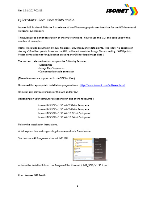
Quick Start Guide: Isomet iMS StudioIsomet iMS Studio v1.30 is the first release of the Windows graphic user interface for the iMS4- series of 4 channel synthezisers.This guide gives a brief description of the iMS4 functions , how to use this GUI and concludes with a number of examples.[Note: This guide assumes individual file sizes < 1024 frequency data points. The iMS4-P is capable of storing >10 million points however the GUI will react slowly for Image files exceeding ~4000 points. Please contact Isomet for guideance on using the GUI for large image sizes ]The current release does not support the following features:- Diagnostics- Image Play Sequences- Compensation table generator(These features are supported in the SDK for C++ ).Download the appropriate installation program from: /software.html Uninstall any prevous versions of the SDK and/or GUIDepending on your computer select and run one of the followimg :Isomet iMS SDK v 1.30 Win7 32-bit Setup.exeIsomet iMS SDK v 1.30 Win7 64-bit Setup.exeIsomet iMS SDK v 1.30 Win10 32-bit Setup.exeIsomet iMS SDK v 1.30 Win10 64-bit Setup.exeFollow the installation instructions.A full explanation and supporting documentation is found underStart menu > All Programs > Isomet iMS SDKor from the installed folder : >> Program Files / Isomet / iMS_SDK / v1.30 / docRun: Isomet iMS Studio.Overview: GUI Windows and tabsOpening windowCentre window is the main input array. This behaves much like a typical spread sheet.- Copy and paste can be applied to individual cells, cell groups, entire rows or columns.- Rows can be deleted or inserted.The array is used to input the Frequency, Amplitude , Phase, and Synchronous output data.The column data is predefined and differs depending on the selected operating mode:Tone buffer(s) modeOne or more tables of 256 frequencies/amplitude/phase (F/A/P) values.∙Columns display the Frequency, Amplitude and Phase values.This is repeated for each of the 4 channels.∙Rows display the buffer entry. Up to 256 max lines per buffer.Array values can be entered directy into the GUI array or copied from an Excel spread sheet. Image files (s) modeOne or more files containing many frequencies/amplitude/phase/sync data points.∙Columns display the Frequency, Amplitude and Phase values PLUS a 12bit wide digital output register and two synchronous output DACs.The F/A/P data is repeated for each of the 4 channels.∙Rows display the image point entry.Image mode is useful for generating larger more complex frequency scan patterns.Values can be entered directy into the GUI array or data copied from an Excel spread sheet .For both modes, the data in selected cells within a column can be auto filled or interpolated.1: Signal Path tabMain purpose this tab is to set the RF power limits and enable RF power amplifer(s) that are connectedto the control outputs of the iMS4 (connector J5 or J6)Overview: Output Power control1.1: The 10-bit Amplitude values specified for each frequency point in the Image File or Tone Buffer.This value is multiplied by a Array Compensation factor stored in acalibration look up table (LUT).The LUT can be bypassed if required.The LUT is applied by default.1.2: DDS Power Level.8-bit non-volatile digital pot.GUI slider control is providedin the Signal Path tab1.3: Amplitude Control Source for the output RF mixers.Selection and slider optionsare provided under theSignal Path tabA typical selection is Wiper 1,which is a 8-bit non-volatiledigital pot with GUI slider controlThe optimum slider settings will depend on the connected RF power amplifier and AO device. Recommended values will be provided on the AO test data sheet supplied with the iMS4- Sliders values will increment/decrement in steps of 0.1 by using the up-down arrow keysSignal Path tab cont’dIn a typical system, the iMS4- will be the frequency source to a power amplifer(s). This in turn is connected to the AO modulator, frequency shifter , deflector or tuneble filter.Depending on the amplifier model, the iMS4- will provide the enable or Gate signal to the external power amplifier(s).Amplifer Enable controlsToggle Buttons, as shown Turn Green when activeExamples:2: Compensation tabA calibration or compensation look-up-table (LUT) contains frequency specific phase and amplitude data. It may be applied to Image and Tone Buffer frequency points in order to :a: to compensate for amplitude non-linearitiesb: apply a predefined phase shift between adjacent RF channels *.* For beam steered AO deflectors with multiple RF inputs, a frequency dependent phase shift “steers”the acoustic column in crystal. This optimizes the Bragg angle relationship resulting in higher effiency across the scan angle. (see App Note “Beam Steered AO Deflectors”)∙LUT values are AO device specific.∙LUT tables can be generated in Excel and converted to the correct format for the GUI. (The Compensation Functions window of the present GUI release is not active)Step 1: Import the desired LUT tableA graphic representation of the selected LUT data will appear in the panel e.g. phaseStep 2: DOWNLOAD into iMS4Download will not abort if no iMS4 is connected.3: Calibration tab (Single Tone output)This mode does not use the input array.Values are controlled using the sliders.The same frequency , amplitude and phase increment are applied across all channels(Channel 1 is always zero phase)Use this mode to check basic iMS4 operation and/or initial AO device alignment.Click Calibration tab on right side toolbarAdjust sliders to the desired value.Use with caution.The Slider limits are fixed and may exceed the range of any connected power amplifier and AO device. The Compensation LUT values are bypassed.Click the large RED button to activate . This will change to Green (arrowed).Click again to disable. It will toggle back to RED.4: Player Configuration tabThese functions apply to the Image File output.e.g. Choice of Trigger and Clock Source.Select the active edge for external clock and/or trigger.Action at the end of the Image play.Check boxes allow selective disabling of the Image mode LUT compensation.WHEN UNCHECKED:- Image point amplitude value is multiplied by 100%- Phase offset = 0 deg all frequencies, all channels.5: Image Play controlTool bar buttonsTo Start image play(Reserved for future use)Stop at end of current Image playStop immediatelyEmergencey Stop, reducing RF power controls to Zero %and disabling any connected power ampsExample 1: Image Mode10 point image on Channel 1 and Channel 2 only.Linear frequency scan : 60-100MHz100% amplitudeCompensation LUT appliedSynchronous output at mid-scan point, data = 255Internal Clock, No trigger, Repeated continuous outputiMS4 only. No connected power amps.1: Enter Number of Image Points2: Input Channel1 frequency end pointsPoint 0, input 60.00 MHz, Point 9, input 100.00 MHzClick on the column header to highlight the cells and right click to reveal the options window. Choose Interpolate to fill in incrementing values between the start and end point frequencies. 3: Input Channel1 AmplitudeClick on the column header to highlight the amplitude cells.Enter 100. A 100% value will auto fill down all highlighted cells.Navigate away from the amplitude column to complete4: Copy to Channel 2Left click cell: Channel1_Frequency_Row 0 to select and highlightNavigate to cell: Channel1_Amplitude_Row 9. Shift- left click this cell.This will select the Frequency and Amplitude data for Channel 1Copy & Paste into Channel 25: Set Synchronous digital output (outputs through connecter J7)Use the lower slider to navigate to the Sync Data columnsInput ‘FF’ at the desired cell(s)Ensure Digital Sync Output Source field is set to ImageDigital[Note for iMS4-L users. Sync data can only applied using the Compensation LUT . In this case the Digital Sync Output Source is set to LookUpFieldCh1]6: Apply Compensation table ∙Import the desired LUT table∙DOWNLOAD into iMS47: Set Player Configuration Image Clock Source: Internal Image Trigger: No TriggerImage Repeats : Repeat forever8: Set power levelsIn this exampleDDS power to 63%Amplitude Control Source is Wiper 1 Wiper 1 setting = 80%9: Start PlayExample 2: Tone Buffer Mode16 tones only.Channel 1: Linear frequency increments, 150-90MHzChannel 1: Linear amplitude slope : 100 – 70%Channel 2: Static frequency increments, 120MHzChannel 2: Static amplitude : 55%No Compensation LUT appliediMS4 only. No connected power amps.At output, Tones selected though the GUI software (USER)1: Click in the Tone Buffer window . Edit the name if desired.or click “ + ” to add another buffer fileThe input array will fill with 256 rows = 256 x 4 channel F/A/P data pointsNot all 256 need be used.In this example we are not applying compensation table.2: Uncheck Amplitude Compensation box, Phase Compensation box3: In the Control Source, select User ** Other options are External and Extended ExternalThe 256 tone buffer (LTB) locations are arranged in 16 pages.Within each page, the 16 F/A/P Tones may be rapidly addressed using 4x external LTB address lines on connector J8. See IMS4- manual for details4: Channel1 Frequency, enter end point valuesTone 0, enter 150.00 MHz 9 (Start) , Tone 15, enter 90.00 MHz (End) 5: Channel1 Amplitude , enter end point valuesTone 0, enter 100 %, Tone 15, enter 70 %6: Channel2 Frequency, enter end point valuesTone 0, enter 120.00 MHz 15 (Start) , Tone 15, enter 120.00 MHz (End) 7: Channel2 Amplitude, enter end point valuesTone 0, input 55 %, Tone 15, input 55 %Use the Interploate feature to fill the remainimg 14 cellsFor each coloum:- Left click on Start cell- Hold down the shift key- Navigate to the end cell and left click(This should select and highlight all 16 cells)- Right click to open sub window- Select Intepolate8: Set power levelsIn this exampleDDS power to 63%Amplitude Control Source is Wiper 1 Wiper 1 setting = 80%9: Enable output10: Tone SelectionClick on then desired Row to output that frequency set11: To disable outputClick as shownExample 3: Calibration ModeUse internal amplitude control, Wiper 1. Apply cautious power settings for initial use. Set slider of AO centre freq e.g. 80MHz External Amplifier connected to J61: Set power level limitsIn this exampleDDS power 40%Amplitude Control Source is Wiper 1 Wiper 1 setting = 30%2: Enable amplifier3: Select Calibration tabAdjust sliders as requiredClick the large RED button to activate . This will change to Green. Click again to disable. It will toggle back to RED.。


摩斯密码自学入门教程摩斯密码(Morse Code)是一种用滴答声和停顿来传输文本信息的方法,是一种早期的无线电通信系统。
由美国研究员西蒙·摩斯创造,他的贡献使无线电在全球范围内的发展得以加速。
摩斯密码也被用于重要场合,如发射航班任务等,它被广泛用于新闻、报刊、商业部门和广播服务。
摩斯密码是传输信息的关键,它使用短音(类似点)和长音(类似划)来传输字母,数字和符号。
摩斯密码在无线电通信当中十分重要,它是由一个赤道准线单元和一个短波发射器组成的。
摩斯密码利用一种叫做解调的过程,它通过在接收者的终端上检测到的信号的控制点来实现。
要想学会摩斯密码,有几件事情需要你注意:首先,在学习如何使用摩斯密码之前,你需要学习字母表。
字母表是由26个字母组成的,它们被分成四组,A-E,F-J,K-O和P-T。
每组使用一种摩斯密码序列来表示,比如字母“A”用“.-”表示,字母“B”用“-...”表示,字母“C”用“-.-.”表示。
其次,学习如何使用解调器。
解调器是一种用于识别摩斯密码的装置。
它可以帮助你检测和测量信号的强度。
使用解调器,你可以更准确地检测摩斯密码,他能够更快地帮助你解码信息。
最后,学习如何接收和发送摩斯密码消息。
接收和发送摩斯密码信息是一种技术活动,需要你有良好的知识和技巧,以及耐心和专注。
你可以先学习几个简单的摩斯密码,然后再学习更复杂的摩斯密码。
学习摩斯密码并不是一件容易的事情,但是它可以帮助你更好地了解无线电领域的工作内容,也可以学习到更多相关的知识。
所以,努力学习吧,这一切都会是值得的!。
telephone速记法如何使用集成电话速记法。
步骤一:了解集成电话速记法集成电话速记法是一种通过快速记录电话对话的技巧,旨在提高记录员的工作效率和准确性。
它采用一种简化的速记系统,使记录员能够准确地记录会话中的重要信息,而不会错过关键细节。
步骤二:准备好工具和材料要使用集成电话速记法,您需要准备一支速记笔和一本速记本。
速记笔应该是您喜欢且熟悉的类型,以确保您的记录速度和准确性。
速记本最好是有线或螺旋绑定,以便翻阅和整理。
步骤三:学习速记符号和缩写集成电话速记法使用一些特殊的符号和缩写来记录电话对话。
例如,您可以使用箭头符号“->”表示对话的方向,使用“T”表示电话呼入,使用“C”表示电话呼出,使用“#”表示电话号码,使用“?”表示不确定的信息,等等。
学习这些符号和缩写,并熟练掌握它们,可以帮助您更快地记录电话对话。
步骤四:提前准备会话的主题和目的在每个电话之前,确保您了解对话的主题和目的。
这将有助于您更好地理解重要信息,并准确记录下来。
如果可能的话,在每个电话之前,预先准备一些问题或要点,以确保您不会错过任何重要信息。
步骤五:专注并提问在电话对话中,保持专注,并尽可能少地打断。
您可以以简洁的方式提出问题或澄清信息,以确保您正确理解对方的意思。
使用缩写和符号记录重要信息,并在适当的时候向对方确认您的记录是否准确。
步骤六:尽快整理和复查记录在电话结束后,尽快整理和复查您的记录。
使用清晰的书写和适当的间距,使记录易于阅读。
复查记录,确保准确性,并校对电话号码和其他关键细节。
如果发现错误或遗漏,尽快进行修正,以免遗漏重要信息。
步骤七:保护记录的隐私性与安全性集成电话速记法需要您记录和处理他人的信息,因此保护隐私性和安全性非常重要。
在处理记录时,要确保记录的存储和访问受到适当的安全措施保护。
要从记录中删除或匿名敏感信息,并定期清理记录以保持数据的安全。
总结:集成电话速记法是一种提高记录员工作效率和准确性的技巧。

下面我们进入正题。
1、样本文件。
本文使用的样本文件可到以下链接下载使用:/Files/Doc/sample1.doc或者,可将以下文本复制到WORD文档当中,命名为sample1.doc。
Sample for Learning TRADOS. (注:请将此句标题的字体设置大一些)Mr. Ray is a translator.Mr. Ray is a translator.He was born in 1949.Mr. Jason is a translator.He was born in 2005.They all use TRADOS in the process of translation.Mr. Ray is a translator.He was born in 1965.Mr. Jason is also a translator.He was born in 1980.He runs a translation website called .2、准备记忆体(事先声明一下,本文使用的是TRADOS7.0版,但是使用其它版本的同行们不用担心,因为各个版本的使用方法基本相同。
)在程序组当中点击Translator's Workbench(下文简称为Workbench),进入Workbench界面。
单击菜单中的文件(File)--新建(New),新建一个记忆库。
如果是第一次使用,会弹出对话框,让您输入用户名(User ID),以后由您在这个记忆库里记下的句段就都是属于这个ID的了。
然后弹出的是建立翻译记忆体对话框(Create Translation Memory),选择您即将翻译的源语言(Source languages)与目标语言(Target languages),本例是英译中,所以在源语言栏当中选择English (United States),在目标语言栏中选择Chinese (PRC),选好了点击“创建”(Create)。

SKU17022,17023SiK Telemetry Radio V3Quick Start GuideOverviewThis Holybro SiK Telemetry Radio is a small, light and inexpensive open source radio platform that typically allows ranges of better than 300m “out of the box” (the range can be extended to several kilometres with the use of a patch antenna on the ground).This radio is plug-n-play all Pixhawk Standard and other Flight Controller, providing the easiest ways to setup a telemetry connection between your Autopilot and a ground station. It uses open source firmware which has been specially designed to work well with MAVLink packets and to be integrated with the Mission Planner, Ardupilot, QGroundControl, PX4 Autopilot.The radios can be either 915Mhz or 433Mhz and you should purchase the model which is appropriate for your country/region.Note:This radio does not support firmware upload via Mission Planner 1.3.75 or order. Please useMission Planner 1.3.75.1 or newer if firmware upload is needed.P a g e | Features⚫Open-source SIK firmware⚫Plug-n-play for Pixhawk Standard Flight Controller⚫Easiest way to connect your Autopilot and Ground Station⚫Interchangeable air and ground radio⚫Micro-USB port (Type-C Adapter Cable Included)⚫6-position JST-GH connectorSpecification⚫100 mW maximum output power (adjustable) -117 dBm receive sensitivity ⚫RP-SMA connector⚫2-way full-duplex communication through adaptive TDM UART interface ⚫Transparent serial link⚫MAVLink protocol framing⚫Frequency Hopping Spread Spectrum (FHSS) Configurable duty cycle⚫Error correction corrects up to 25% of bit errors Open-source SIK firmware ⚫Configurable through Mission Planner & APM Planner⚫FT230X is a USB to BASIC UART ICDimensions⚫28 x 53 x 10.7mm (without antenna)Electrical Data⚫Supply voltage: 5V DC (from USB or JST-GH)⚫Transmit current: 100 mA at 20dBm⚫Receive current: 25 mA⚫Serial interface: 3.3 V UARTProduct DescriptionLEDs Indicators StatusThe radios have 2 status LEDs, one red and one green.The meanings of the different LED states are:Green LED blinking - searching for another radioGreen LED solid - link is established with another radioRed LED flashing - transmitting dataRed LED solid - in firmware update modeConnecting to Pixhawk Standard Flight ControllerUse the 6 pin JST-GH connector that come with the radio to connect the radio to your flight controller's “Telem 1” (“Telem 2” can also be used but the default recommendation is “Telem1”).Connecting to a PC or Ground StationConnecting the radio to your Windows PC or Ground Station is as simple as connecting the micro/type-C USB cable (both included with the radio) to your PC/Ground Station.The necessary drivers should be installed automatically and the radio will appear as a new “USB Serial Port” in the Windows Device Manager under Ports (COM & LPT). The Mission Planner’s COM Port selection drop-down should also contain the same new COM port.Package IncludedRadio modules with antennas *2Micro-USB to USB-A cable *1Micro-USB to Micro-USB OTG adapter cable *1Micro USB to Type C AdapterJST-GH-6P to JST-GH-6P cable *1 (for Pixhawk Standard FC)JST-GH-6P to Molex DF13 6P (for Pix32, Pixhawk 2.4.6, etc.)Holybro is a registered trademark of Holybro, registered in the U.S. and other countries.©Copyright 2018 Holybro. All Rights Reserved.。
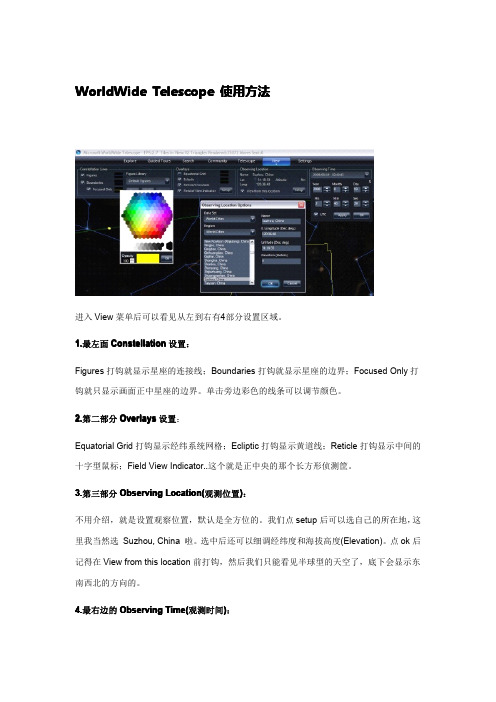
WorldWide Telescope使用方法进入View菜单后可以看见从左到右有4部分设置区域。
1.最左面Constellation设置:Figures打钩就显示星座的连接线;Boundaries打钩就显示星座的边界;Focused Only打钩就只显示画面正中星座的边界。
单击旁边彩色的线条可以调节颜色。
2.第二部分Overlays设置:Equatorial Grid打钩显示经纬系统网格;Ecliptic打钩显示黄道线;Reticle打钩显示中间的十字型鼠标;Field View Indicator..这个就是正中央的那个长方形侦测筐。
3.第三部分Observing Location(观测位置):不用介绍,就是设置观察位置,默认是全方位的。
我们点setup后可以选自己的所在地,这里我当然选Suzhou,China啦。
选中后还可以细调经纬度和海拔高度(Elevation)。
点ok后记得在View from this location前打钩,然后我们只能看见半球型的天空了,底下会显示东南西北的方向的。
4.最右边的Observing Time(观测时间):配合前面的观测位置,点下拉箭头,默认是格林尼的时间,去掉钩则和电脑时间同步。
和北京时间有时差的地方就手动调节时间吧,然后ok。
(注意,开始当前时间和位置后整个天空会实时转动,可以按暂停按钮暂停转动。
)完成这些设置,展现在眼前的就是当前的星空景象啦。
然后顺手进下一个Setting设置。
如图(同上理由,点这个看大图:这里也是4个部分,还是从左到右的来。
1.Solar System Option太阳系相关的选项,从上往下依次是:显示太阳系天体/高精度模式/显示行星实际大小/把卫星(月亮)显示成一个点。
2.Earth and Planets地球相关选项,上面是显示云层,下面是显示海拔。
这些设置只在观测地球时候有效(见下面内容栏Look at介绍)。
那个云层显示不知道是不是即时的,是的话就可以当气象软件了哈。
telegram 技巧Telegram是一款非常受欢迎的聊天应用程序,它提供了一些很好的工具和功能。
不仅它提供了跨平台使用,还允许您加密聊天和媒体共享。
在这份文档中,我们将讨论Telegram的各种技巧,帮助您在使用这一应用时更加便利和高效。
1. 了解机器人Telegram的机器人是可以帮助您自动化操作的程序。
许多站点和应用程序都提供Telegram机器人,它们可以用于许多不同的用途,如新闻聚合、天气预报、产品价格监控等等。
要使用一个机器人,只需在Telegram中搜索其名称并关注即可。
一旦与机器人建立联系,您可以通过发送不同的消息来与它互动。
机器人还支持指令(/command),根据机器人的不同,这些指令可以用于执行不同的任务。
2. 投票Telegram中的投票功能是非常有用的。
您可以通过向群组发送投票来获取群组中成员的意见,也可以在1对1聊天中使用它。
使用投票功能将各种选项显示给其他人,让其他人选择它们最喜欢的选项。
投票功能也可以帮助您组织和计划团队活动。
要创建投票,请从键盘中选择投票图标并按照提示创建投票。
3. 隐藏聊天Telegram中的隐藏聊天功能允许您隐藏聊天会话,以保护隐私。
要隐藏聊天,请轻轻向左滑动您要隐藏的聊天记录,并选择“隐藏”。
4. 创建链接Telegram允许您创建链接,使其他人可以轻松地访问您想要共享的内容。
链接可以是聊天组,频道,甚至可以指向一个特定的信息。
要创建连接,请长按您要共享的内容,并选择“共享链接”。
5. 快捷键Telegram中的快捷键是可以帮助您提高效率的好工具。
快捷键允许您通过键盘上的特殊组合键来执行不同的任务,如新建聊天或快速搜索信息。
快捷键的具体组合取决于你的设备,您可以在Telegram的设置中查找每个特殊功能的组合。
6. 定时消息定时消息功能允许您在未来的某个时间发送消息。
例如,如果您想在非工作时间通知某人,请设置定时消息,以便在第二天上班时间发送。
摩尔斯电报使用训练讲义一、教学目标1.了解摩尔斯电报的历史和基本原理,包括发明者、应用领域和通信方式等。
2.掌握摩尔斯电报的拍发技巧,包括正确的姿势、手指的力量和节奏等。
3.掌握摩尔斯电报的接收技巧,包括如何调整接收机的灵敏度、如何分辨不同的点和划等。
4.能够准确快速地传递信息和解读摩尔斯电报,达到在紧急情况下能够迅速有效地进行通信的目的。
二、教学内容1.摩尔斯电报的历史和基本原理•摩尔斯电报的发明者萨缪尔·摩尔斯及其贡献。
•摩尔斯电报的基本原理:通过点和划的组合表达字母、数字和符号。
•摩尔斯电报在历史上的应用领域,如航海、军事等。
2.摩尔斯电报的拍发技巧•正确的拍发姿势:坐姿端正,双脚平放地面,双手舒适地放在键盘上,身体微微前倾。
•手指的力量:适当的力量能够保证清晰度和速度,避免疲劳。
•节奏的掌握:快速的点和划交替,保持稳定和节奏感。
3.摩尔斯电报的接收技巧•调整接收机的灵敏度:根据不同的环境和信号强度,调整接收机的灵敏度以达到最佳接收效果。
•分辨不同的点和划:通过声音的节奏和大小,准确地分辨点和划。
•注意信号干扰:在存在干扰的情况下,注意信号的变化和干扰源。
4.摩尔斯电报的实际应用和操作•练习材料:提供预先编制的摩尔斯电报练习材料,包括不同难度和主题的练习。
•操作流程:指导学员按照操作流程进行拍发和接收练习,强调准确性和速度。
•操作问题:解答学员在操作过程中遇到的问题,指导其正确使用摩尔斯电报。
三、教学过程1.导入(10分钟)•介绍摩尔斯电报的历史和基本原理,让学员了解摩尔斯电报的发明和应用,以及在军事通信中的重要地位。
•展示摩尔斯电报机的图片和模型,让学员了解其外观和结构。
2.拍发训练(20分钟)•讲解正确的拍发姿势和手指的力量,并进行示范。
•带领学员进行基本的拍发练习,强调节奏和稳定。
•对学员的拍发进行指导和纠正,确保其掌握正确的技巧。
3.接收训练(20分钟)•讲解如何调整接收机的灵敏度和分辨不同的点和划,并进行示范。
莫斯机及专业设备使用操作莫斯机以及专业设备,是一类广泛应用于通信、电报和电信领域的设备。
它们在信息传递和通讯中起着重要的作用。
为了正确地操作和使用莫斯机及专业设备,我们需要了解其基本原理和操作规范。
本文将介绍莫斯机及专业设备的使用操作,并提供一些实用的操作技巧。
一、莫斯机概述莫斯机,又称摩尔斯键控电报机,是一种通过电信号传输英文字符的设备。
它采用了斯堪的纳维亚电码,将英文字母、数字、标点符号等转换为短音和长音的组合来表示,通过电报线路传输信息。
莫斯机的使用需要掌握摩尔斯电码和相应操作技巧。
二、莫斯机的基本操作步骤1. 打开莫斯机电源并进行初始化。
对于机械式的莫斯机,还需检查机械部分的运行情况。
2. 调整莫斯机的音量和音调,以适应操作者的听觉感受。
3. 熟悉莫斯机键盘和操作按钮的位置,了解各个按键的功能。
4. 开始输入摩尔斯电码。
通过按下按键,按照英文字符对应的摩尔斯电码输入字符。
5. 每输入一个字符后,等待一段时间以便接收方接收信号。
6. 输入完整的单词后,用一个稍长的时间间隔表示单词结束。
7. 输入完整的句子后,用一段较长的时间间隔表示句子结束。
三、专业设备的使用操作除了莫斯机,还有许多其他专业设备在不同领域得到广泛应用,如医疗设备、科学实验仪器等。
使用这些专业设备需要遵循一定的操作规范和注意事项。
1. 阅读说明书和操作手册。
在使用任何专业设备之前,首先要详细阅读相关的说明书和操作手册。
了解设备的安装、调试以及使用方法。
2. 进行设备的安全检查。
确保设备的连接正常、电源稳定,并按照要求进行设备的校准和预热等操作。
3. 严格按照操作流程进行。
根据设备操作手册中给出的操作流程,按照步骤进行,不得随意操作或尝试其他方式。
4. 注意设备的维护和保养。
对于长期使用的专业设备,定期进行维护和保养是十分重要的,可以延长设备的使用寿命和保证设备的可靠性。
5. 注意安全和卫生问题。
在使用一些特殊的专业设备时,应注意个人的安全和卫生,比如佩戴防护装备、遵循操作规范等。

汽车电子的下一步——Telematics
艾伦
【期刊名称】《《电子与电脑》》
【年(卷),期】2006(000)011
【总页数】5页(P94-98)
【作者】艾伦
【作者单位】
【正文语种】中文
【中图分类】F426.471
【相关文献】
1.数字电视怎样在Telematics中应用——介绍韩国SK Car Life Telematics发展状况 [J],
2.智能网联、信息安全、车载以太网,汽车电子行业热点趋势大探讨——2016(第四届)国际汽车电子创新技术论坛暨汽车电子创新产品评选颁奖典礼在沪举办[J], ;
3.汽车电子行业热点趋势大探讨——“2016(第四届)国际汽车电子创新技术论坛暨汽车电子创新技术评选颁奖典礼”在沪举办 [J], ;
4.汽车电子的下一步——Telematics [J], 艾伦
5.赛格导航中国领先的Telematics车载智能信息终端制造商中国Telematics汽车在线服务开拓者公司简介 [J],
因版权原因,仅展示原文概要,查看原文内容请购买。

0欧阻抗50欧阻抗无穷大所有绿色为导纳圆所有红色为阻抗圆串联电感电容电阻,line 为微带线并联电感电容电阻,TRANSF 为变压器.圆下半部分为容性-圆上半部分为感性+ 输入阻抗和频率负载端源端特性阻抗为50 驻波比Q 值极坐标形式: 模、角导纳,阻抗加电阻移动轨迹1. 一开始选Keyboard :2.例子, 一个40+80J 的电路要匹配到50欧,在2.4G 的时候.1. 点击DATSPUN ,选择Keyboard 键盘输入2. 输入40和80和2.4GHZ输入的为阻抗阻抗实部阻抗虚部频率笛卡尔坐标 极坐标反射系数 导纳(单位:S 西门子)3.点击串联电容C, 点1开始往下转,在点2处单击左键停止.4.点击并联电容C, 点2开始往点3跑,在点3(点3为50欧)点击左键,即完成匹配。
点击串C5. 匹配电路为:40+80j欧50欧一个电路为负载40+80j阻抗经过串联一个1.1PF的电容,和并联一个660Ff=0.66PF的电容。
达到了L型匹配。
(此图651.2fF和660.8fF有点误差,没有关系的,是一样的。
那是因为鼠标没有点准)要领:1.smith史密斯图用于阻抗匹配2.圆上的任何点都是阻抗.3.红色是阻抗圆,绿色是导纳圆。
4.圆心是50欧,最左是0欧,最右是无穷大电阻。
5.圆的上半部分是感抗(比如5-6j)下半部分是容抗.(比如3+2j)6.加电感向上转,加电容向下转.(加电阻沿着电阻线跑,一般用不着电阻)7. 串联沿着红色圆(阻抗圆)移动,并联沿着绿色圆(导纳圆)移动.8.阻抗有几种数学表示方法,一个是复数的形式,比如40+80J, 一个是极坐标的形式.9.一般每次都要转到和50阻抗圆或0.02导纳圆处,再换下一个元件.第9条的解析,一般要移动到0.02或50这个圆上,然后再换元件.。

直立手键电码拍发技巧用直立手键拍发莫尔斯电码是个古老的技术,目前还坚持用直立手键的人已经不多。
在 HAM 中也同样,通联或比赛中使用直立手键的朋友寥寥无几。
上次我听香港的一个 HAM 说过,美国众多HAM 曾经在网上讨论得出的结论是:直立手键在世界 HAM 中几乎灭绝了,大家还喜欢手键主要原因是为了收藏和怀念。
但是据我了解,我们周边喜爱直立手键的朋友非常之多,而使用直立手键通联的却很少,主要是大家都有畏难情绪,喜爱它,但又怕难学。
其实只要掌握正确的学习方法,克服畏难情绪,经过刻苦练习大家都会成功的。
在无线电通信中,用电键把电码符号传递给对方,叫做发报。
目的是让对方正确的把报文抄收下来。
如果您发的报不正规或有毛病,致使对方无法抄收或辨别,就难以完成电码的传递任务。
所以,正规、流利、快捷的电码拍发很重要。
电键的调整以常用的直立手键 K4 电键为例,键梁支架螺丝是固定键梁的,为了保持键梁的灵活性,支架螺丝不易拧的太紧,但两边固定螺母要拧紧,防止键梁脱落。
然后根据个人情况调整触点的大小和弹簧的软硬程度,初学者弹簧硬一些,触点间隔大一些。
调整好后都需要把固定螺母拧紧。
我平常电键触点间隙大概 0.5mm ,触点接触时键钮的压力大概 1kg 。
我的报训队老师曾经对我们这些学员说过,电键弹簧越硬越不容易坏手。
所以,几十年我的电键弹簧硬度始终为 1kg ,比较硬,所以从来没有坏过手。
手键报电码拍发时的坐姿上身自然挺直,两脚与肩同宽平稳放置在地面,身体离操作台十五公分左右,右手握键,大臂自然下垂,小臂与电键保持在一条直线上,肘部与身体保持十公分间隔。
键钮置于操作台边沿位置。
左手按住报底,眼睛注视报底。
握键姿势一般手键拍发有两种握姿:一个是立姿,一个是跪姿。
立姿:食指立在键钮顶上,自然弯曲成弧形,拇指与中指合力捏住键钮的腰部。
跪姿:中指用第一个关节跪在键钮底盘右侧之上,拇指捏住键钮左侧腰部,食指和立姿相同,站立在键钮顶部,自然弯曲成弧形。