Study on detection method of voltage sag characteristics for power system
- 格式:pdf
- 大小:92.71 KB
- 文档页数:2
1、高电压试验技术GB/T16927 高电压试验技术[1] GB/T 16927.1-1997, 高电压试验技术 第一部分: 一般试验要求High voltage test techniques--Part 1: General test requirements[2] GB/T 16927.2-1997, 高电压试验技术 第二部分:测量系统High voltage test techniques--Part 2: Measuring systemsGB/T 17627 低压电气设备的高电压试验技术[1] GB/T 17627.1-1998, 低压电气设备的高电压试验技术 第一部分:定义和试验要求High-voltage test techniques for low-voltage equipment Part 1: Definitions,test and procedure requirements[2] GB/T 17627.2-1998, 低压电气设备的高电压试验技术 第二部分:测量系统和试验设备High-voltage test techniques for low-voltage equipment Part2:Measuring system and test equipmentDL/T 848 高压试验装置通用技术条件[1] DL/T 848.1-2004, 高压试验装置通用技术条件 第1部分:直流高压发生器General technical specification of high voltage test devices Part 1: High voltage DC generator [2] DL/T 848.2-2004, 高压试验装置通用技术条件第2部分:工频高压试验装置General technical specification of high voltage test devices Part 2: Power frequency high voltage test device[3] DL/T 848.3-2004, 高压试验装置通用技术条件第3部分:无局放试验变压器General technical specification of high voltage test devices Part 3: Non partial discharge testing transformer[4] DL/T 848.4-2004, 高压试验装置通用技术条件第4部分:三倍频试验变压器装置General technical specification of high voltage test devices Part4:Triple-frequency test transformer[5] DL/T 848.5-2004, 高压试验装置通用技术条件 第5部分:冲击电压发生器General technical specification of high voltage test devices Part 5 : impulse voltage generatorDL/T846 高电压测试仪器通用技术条件[1] DL/T 846.1-2004, 高电压测试设备通用技术条件 第1部分:高电压分压器测量系统General technical specifications for high voltage test equipments Part 1 : high voltage divider measuring system[2] DL/T 846.2-2004, 高电压测试设备通用技术条件 第2部分:冲击电压测量系统General technical specifications for high voltage test equipments Part2:Impulse voltage measuring system[3] DL/T 846.3-2004, 高电压测试设备通用技术条件 第3部分:高压开关综合测试仪General technical specifications for high voltage test equipments Part 3: High voltage switch integrate detector[4] DL/T 846.4-2004, 高电压测试设备通用技术条件 第4部分:局部放电测量仪General technical specifications for high voltage test equipments Part 4: Partial discharge detector [5] DL/T 846.5-2004, 高电压测试设备通用技术条件 第5部分:六氟化硫微量水分仪General technical specifications for high voltage test equipments Part5: Analyzer for trace moisture in SF6 gas[6] DL/T 846.6-2004, 高电压测试设备通用技术条件 第6部分:六氟化硫气体检漏仪General technical specifications for high voltage test equipments Part 6: SF6 gas leak detector [7] DL/T 846.7-2004, 高电压测试设备通用技术条件 第7部分:绝缘油介电强度测试仪General technical specifications for high voltage test equipments Part7:Dielectric strength detector of insulating oils[8] DL/T 846.8-2004, 高电压测试设备通用技术条件 第8部分:有载分接开关测试仪General technical specifications for high voltage test equipments Part 8: Detector of on-load tap-changers[9] DL/T 846.9-2004, 高电压测试设备通用技术条件 第9部分:真空开关真空度测试仪General technical specifications for high voltage test equipments Part 9: Vacuum interrupter detectorIEC标准[1] IEC 60060-1-2010 高压试验技术.第1部分:一般定义和试验要求High-voltage test techniques - Part 1: General definitions and test requirements[2] IEC 60060-2-2010 高压试验技术.第2部分:测量系统High-voltage test techniques. Part 2: Measuring systems[3] IEC 60060-3-2006 高压试验技术.第3部分:现场试验的定义和要求High voltage test techniques - Part 3: Definitions and requirements for on-site testing[4] IEC 60060-4-1988 高压试验技术.第4部分:测量装置应用导则High-voltage test techniques. Part 4 : Application guide for measuring devices[5] IEC 60270-2000 高电压试验技术:局部放电测量High-V oltage Test Techniques – Partial Discharge Measurements-Third EditionIEEE标准[1] 4-1995 IEEE Standard Techniques for High-V oltage Testing (Revision of IEEE Std 4-1 978)[2] 4a-2001 Amendment to IEEE Standard Techniques for High-V oltage Testing[3] 48-2009 IEEE Standard for Test Procedures and Requirements for Alternating-Current Cable Terminations Used on Shielded Cables Having Laminated Insulation Rated 2.5 kV through 765 kV or Extruded Insulation Rated 2.5 kV through 500 kV[4] 95-2002 IEEE Recommended Practice for Insulation Testing of AC Electric Machinery (2300 V and Above) With High Direct V oltage[5] 400.1-2007 IEEE Guide for Field Testing of Laminated Dielectric, Shielded Power Cable Systems Rated 5 kV and Above With High Direct Current V oltage[6] 400-2001 IEEE Guide for Field Testing and Evaluation of the Insulation of Shielded Power Cable Systems[7] 433-2009 IEEE Recommended Practice for Insulation Testing of AC Electric Machinery with High V oltage at Very Low Frequency[8] C37.09-2005 IEEE Standard Test Procedure for AC High-V oltage Circuit Breakers Rated on aSymmetrical Current Basis[9] C37.081-1981 IEEE Guide for Synthetic Fault Testing of AC High-V oltage Circuit Breakers Rated on a Symmetrical Current Basis[10] C37.083-1999 IEEE Guide for Synthetic Capacitive Current Switching Tests of AC High-V oltage Circuit Breakers[11] C37.34-1994 IEEE Standard Test Code for High-V oltage Air Switches[12] C37.41-2008 IEEE Standard Design Tests for High-V oltage (>1000 V) Fuses, Fuse and Disconnecting Cutouts,Distribution Enclosed Single-Pole Air Switches,Fuse Disconnecting Switches, and Fuse Links and Accessories Used with These Devices[13] C37.53.1-1989 American National Standard High-V oltage Current-Limiting Motor-Starter Fuses - Conference Test Procedures[14] C37.301-2009 IEEE Standard for High-V oltage Switchgear (Above 1000 V) Test Techniques - Partial Discharge Measurements[15] C37.016 :2006 IEEE Standard for AC High-V oltage Circuit Switchers rated 15.5 kV through 245 kV二、冲击电压发生器和冲击电压试验[1] DL/T 846.2-2004, 高电压测试设备通用技术条件 第2部分:冲击电压测量系统General technical specifications for high voltage test equipments Part2:Impulse voltage measuring system[2] DL/T 992-2006,冲击电压测量实施细则Detailed implementation guide for impulse voltage measurement[3] JB/T 7083-1993, 低压电器冲击电压试验仪未注英文名称[4] JB/T 7080-1993, 绕组匝间冲击电压试验仪未注英文名称[5] DL/T848.5-2004, 高压试验装置通用技术条件 第5部分:冲击电压发生器General technical specification of high voltage test devices Part 5 : impulse voltage generator [6] GB/T 16896.1-2005, 高电压冲击测量仪器和软件 第1部分:对仪器的要求Instruments and software used for measurements in high-voltage impulse tests-Part1: Requirements for instruments[7] GB/T 21222-2007, 绝缘液体 雷电冲击击穿电压测定方法Methods for the determination of the lightning impulse breakdown voltage of insulating liquids [8] GB/T 18134.1-2000, 极快速冲击高电压试验技术 第1部分:气体绝缘变电站中陡波前过电压用测量系统High-voltage testing techniques with very fast impulses --Part 1:Measuring systems for very fast from overvoltages generated in gas-insulated substations[9] DL/T557- 2005, 高压线路绝缘子空气中冲击击穿试验―定义、试验方法和判据Insulators of ceramic or glass material overhead lines with a nominal voltage greater than 1000V -- impulse puncture tests in air[10] GB/T 1094.4-2005, 电力变压器 第4部分:电力变压器和电抗器的雷电冲击和操作冲击试验导则Power transformers—Part 4:Guide to the lightning impulse and switching impulse testing—Power transformers and reactors[11] GB/T 17626.5-2008, 电磁兼容 试验和测量技术 浪涌(冲击)抗扰度试验Electromagnetic compatibility - Testing and measurement techniques - Surge immunity test [12] GB/T 14598.18-2007, 电气继电器 第22-5部分:量度继电器和保护装置的电气骚扰试验-浪涌抗扰度试验Electrical relays—Part22-5:Electrical disturbance test for measuring relays and protection equipment—Surge immunity test[13] JB/T 7616-1994, 高压线路绝缘子陡波冲击耐受试验未注英文名称[14] DL/T 557-2005, 高压线路绝缘子空气中冲击击穿试验―定义、试验方法和判据Insulators of ceramic or glass material overhead lines with a nominal voltage greater than 1000V -- impulse puncture tests in airIEC标准[1] IEC 60897-1987 绝缘液体的雷电冲击击穿电压的测定方法Methods for the determination of the lightning impulse breakdown voltage of insulating liquids [2] IEC 61083-1-2001 高压冲击试验中测量用仪器及软件 第1部分:仪器的要求 Instruments and software used for measurement in high-voltage impulse tests-Part1: Requirements for instruments[3] IEC 61083-2-1996 高压冲击试验中测量用数字记录仪 第2部分:测定冲击波形参数用软件的评估Digital recorders for measurements in high-voltage tests - Part 2: Evaluation of software used for the determination of the parameters of impulse waveformsIEEE标准[1] 82-2002 IEEE Standard Test Procedure for Impulse V oltage Tests on Insulated Conductors[2] C37.013a-2007 IEEE Standard for AC High V oltage Generator Circuit Breakers Rated on a Symmetrical Current Basis - Amendment 1: Supplement for Use With Generators Rated 10-100 MV A[3] C37.101 :2006 IEEE Guide for Generator Ground Protection[4] C37.102 :2006 IEEE Guide for AC Generator Protection[5] C57.98-1993 IEEE Guide for Transformer Impulse Tests[6] 1122-1998 IEEE Standard for Digital Recorders for Measurements in High- V oltage Impulse Tests[7]C57.138-1998IEEE Recommended Practice for Routine Impulse Test for Distribution Transformers3、工频试验变压器和工频电压试验[1] JB/T 9641—1999,试验变压器Testing transformers[2] JB/T 501-2006 电力变压器试验导则Test guide for power transformers[3] DL/T 848.2-2004, 高压试验装置通用技术条件第2部分:工频高压试验装置General technical specification of high voltage test devices Part 2: Power frequency high voltage test device[4] DL/T 848.3-2004, 高压试验装置通用技术条件第3部分:无局放试验变压器General technical specification of high voltage test devices Part 3: Non partial discharge testing transformer[5] GB/T 1408.1-2006, 绝缘材料电气强度试验方法 第1部分:工频下试验Electrical strength of insulating materials - Test methods - Part 1: Tests at power frequencies [6] GB2536—1990 ,变压器油Transformer oils[7] GB/T 17626.28-2006, 电磁兼容 试验和测量技术 工频频率变化抗扰度试验Electromagnetic compatibility(EMC) - Testing and measurement techniques - Variation of power frequency immunity test[8] GB/T 3333-1999, 电缆纸工频击穿电压试验方法Cable paper--Determination of electrical strength at power frequence[9] GB/T 14517-1993, 绝缘胶粘带工频耐电压试验方法Test method for dielectric strength of insulating adhesive tape at power frequency[10] DL/T 812-2002, 标称电压高于1000V架空线路绝缘子串工频电弧试验方法Insulators string for overhead lines with a normal voltage above 1000V-AC power arc test method [11] GB/T 7252-2001, 变压器油中溶解气体分析和判断导则Guide to the analysis and the diagnosis of gases dissolved in transformer oil[12] DL/T 536-1993, 耦合电容器及电容分压器订货技术条件未注英文名称[13] JB/T 8169-1999, 耦合电容器及电容分压器Coupling capacitors and capacitor dividersGB1094 电力变压器[1] GB 1094.1—1996 ,电力变压器 第1部分:总则Power transformers--Part 1: General[2] GB 1094.2—1996 ,电力变压器 第2部分:温升Power transformers--Part 2: Temperature rise[3] GB 1094.3—2003,电力变压器 第3部分: 绝缘水平、绝缘试验和外绝缘空气间隙(eqv IEC 60076-3:2000)Power transformers--Part 3 : Insulation levels,dielectric tests and external clearances in air[4] GB/T 1094.4-2005, 电力变压器 第4部分:电力变压器和电抗器的雷电冲击和操作冲击试验导则Power transformers—Part 4:Guide to the lightning impulse and switching impulse testing—Power transformers and reactors[5] GB 1094.5—2008 ,电力变压器 第5部分:承受短路的能力Power transformers--Part 5: Ability to withstand short circuit[6] GB/T 1094.7-2008, 电力变压器 第7部分:油浸式电力变压器负载导则Power transformers—Part7:Loading guide for oil-immersed power transformers[7] GB/T 1094.10-2003, 电力变压器 第10部分:声级测定Power transformers—Part10:Determination of sound levels[8] GB 1094.11—2007,电力变压器 第11部分:干式变压器Power transformers--Part 11 : Dry-type transformersIEC标准[1] IEC 60076-10-1-2005 电力变压器.第10-1部分:声级的测定.应用指南Power transformers Part 10-1: Determination of sound levels Application guide-Edition 1[2] IEC 60076-10-2005 电力变压器.第10部分:声级的测定Power Transformers Part 10: Determination of Sound Levels[3] IEC 60076-11-2004 电力变压器.第11部分:干式变压器Power transformers Part 11: Dry-type transformers-First Edition[4] IEC 60076-12-2008 电力变压器.第12部分:干型电力变压器用负荷指南Power transformers - Part 12: Loading guide for dry-type power transformers[5] IEC 60076-13-2006 电力变压器.第13部分:自我保护式充液变压器[6] IEC 60076-15 Ed.1.0 (2008) Power transformers - Part 15: Gas-filled power transformers[7] IEC 60076-15-2008 电力变压器.第15部分:充气电力变压器Power transformers – Part 15: Gas-filled power transformers[8] IEC 60076-2-1993 电力变压器 第2部分:温升Power Transformers; Part 2: Temperature Rise-Second Edition[9] IEC 60076-3-2000 电力变压器 第3部分:绝缘水平、电介质试验和空气中的外间隙Power Transformers Part 3: Insulation Levels. Dielectric Tests and External Clearances in Air-Edition 2[10] IEC 60076-4-2002 电力变压器.第4部分:闪电脉冲和开关脉冲试验指南.电力变压器和电抗器Power transformers - Part 4: Guide to lightning impulse and switching impulse testing; Power transformers and reactors[11] IEC 60076-5-2006 电力变压器 第5部分:承受短路的能力Power Transformers Part 5: Ability to Withstand Short Circuit-Edition 3.0[12] IEC 60076-6-2007 电力变压器.第6部分:电抗器Power transformers – Part 6: Reactors-Edition 1.0[13] IEC 60076-7-2005 电力变压器.第7部分:油浸电力变压器负载指南Power transformers Part 7: Loading guide for oil-immersed power transformers-First Edition [14] IEC 60076-8-1997 电力变压器 第8部分:应用指南Power Transformers - Application Guide-First Edition[15] IEC/TS 60076-14-2004 电力变压器.第14部分:使用高温绝缘材料的液浸式电力变压器的设计和应用Power transformers – Part 14: Design and application of liquid-immersed power transformersusing high-temperature insulation materials-Edition 2.0[16] IEC 62032-2005, 移相变压器的应用、规范和试验指南Guide for the application. specification. and testing of phase-shifting transformersIEEE标准[1] 62.2-2004 IEEE Guide for Diagnostic Field Testing of Electric Power Apparatus - Electrical Machinery[2] 62-1995 IEEE Guide for Diagnostic Field Testing of Electric Power Apparatus - Part 1: Oil Filled Power Transformers, Regulators, and Reactors[3] C57.135-2005 IEEE Guide for the Application, Specification, and Testing of Phase-Shifting Transformers[4] 644-1994 IEEE Standard Procedures for Measurement of Power Frequency Electric and Magnetic Fields From AC Power Lines4、工频谐振试验设备和试验技术[1] DL/T 849.6-2004, 电力设备专用测试仪器通用技术条件 第6部分:高压谐振试验装置General technical specification of test instruments used for power equipments Part 6: High voltage resonant test system5、冲击电流发生器和冲击电流试验技术[1] GB 4208-2008, 外壳防护等级Degrees of protection provided by enclosure[2] GB 18802.1-2002, 低压配电系统的电涌保护器(SPD)第1部分:性能要求和试验方法Surge protective devices connected to low-voltage power distribution systems--Part 1:Performance requirements and testing methods[3] GB 11032-2000 交流无间隙金属氧化物避雷器Metal oxide surge arresters without gaps for a. c. systems[4] GB/T 18802.311-2007 低压电涌保护器件 第311部分:气体放电管(GDT)规范(等同IEC 61643-311-2001)Components for low-voltage surge protective—Part311:Specification for gas discharge tubes(GDT)[5] GB/T 17626.5-2008, 电磁兼容 试验和测量技术 浪涌(冲击)抗扰度试验Electromagnetic compatibility - Testing and measurement techniques - Surge immunity testIEC标准[1] IEC TR 61000-1-5 :2004 Electromagnetic compatibility (EMC) Part 1-5: General High power electromagnetic (HPEM) effects on civil systems-First Edition[2] IEC 60099-4 AMD 2 :2009 AMENDMENT 2 Surge arresters – Part 4: Metal-oxide surge arresters without gaps for a.c. systems-Edition 2.0[3] IEC 61643-311 :2001 Components for Low-V oltage Surge Protective Devices - Part 311: Specification for Gas Discharge Tubes (GDT)-First Edition[4] IEC 61643-1 :2005 Low-voltage surge protective devices – Part 1: Surge protective devices connected to low-voltage power distribution systems – Requirements and tests-Edition 2.0[5] IEC 61643-12 :2008 Low-voltage surge protective devices – Part 12: Surge protective devices connected to low-voltage power distribution systems–Selection and application principles-Edition 2.0IEEE标准[1] C62.11a-2008 IEEE Standard for Metal-Oxide Surge Arresters for Ac Power Circuits (>1 kV). Amendment 1: Short-Circuit Tests for Station, Intermediate, and Distribution Arresters[2] C62.11-2005 IEEE Standard for Metal-Oxide Surge Arresters for AC Power Circuits (>1 kV)[3] C62.22-2009 IEEE Guide for the Application of Metal-Oxide Surge Arresters for Alternating-Current Systems[4] 1299/C62.22.1-1996 IEEE Guide for the Connection of Surge Arresters to Protect Insulated, Shielded Electric Power Cable Systems[5]C62.34-1996IEEE Standard for Performance of Low-V oltage Surge-Protective Devices (Secondary Arresters)[6] C62.41.1-2002 IEEE Guide on the Surge Environment in Low-V oltage (1000 V and less) AC Power Circuits[7] C62.41.2-2002 IEEE Recommended Practice on Characterization of Surges in Low-V oltage (1000 V and Less) AC Power Circuits[8] C62.41-1991 IEEE Recommended Practice on Surge V oltages in Low-V oltage AC Power Circuits[9] C62.42-2005 IEEE Guide for the Application of Component Surge-Protective Devices for Use in Low-V oltage [Equal to Or Less Than 1000 V (AC) Or 1200 V (DC)] Circuits[10] C62.62-2010 IEEE Standard Test Specifications for Surge-Protective Devices (SPDs) for Use on the Load Side of the Service Equipment in Low V oltage (1000 V and less) AC Power Circuits[11] C62.62-2000 IEEE Standard Test Specifications for Surge-Protective Devices for Low-V oltage AC Power Circuits6、其他GB 311.1-1997,高压输变电设备的绝缘配合Insulation co-ordination for high voltage transmission and distribution equipmentGB/T11920-2008, 电站电气部分集中控制设备及系统通用技术条件General specification of central control equipment and system for electrical parts in power stations and substationsGB/T 7354-2003, 局部放电测量Partial discharge measurementsJB/T 8749.1-2007, 调压器 第一部分:通用要求和试验V oltage regulators--Part 1: General requirements and testsJB/T 7070.1-2002 ,调压器试验导则 第1部分:接触调压器和接触自动调压器试验导则Test guide for regulator Part 1: Test guide for variable regulators and automatic variable regulators GB/T 191-2008, 包装储运图示标志Packaging - Pictorial marking for handling of goods。
原电池电动势的测定摘要:本实验采用对消法测定原电池的可逆电动势,为了使电池反应在接近热力学可逆条件下进行,使用电位差计测量。
制作Cu电极和Zn电极,通过盐桥连接制作原电池,掌握一些电极的制备和处理方法。
并且通过电池电动势的测定研究构成此电池的化学反应的热力学性质,进而学会有关热力学函数的计算。
Abstract :This experiment use the compensation method to measure the emf of the reversible battery, and use the potentiometer in order to make the process of the battery reaction thermodynamically reversible.And learn some preparation of electrode and salt bridge by making the Zn electrode and Cu electrode and using the salt bridge to make the battery. And we can study the thermodynamic property of the chemical reaction according to the experimental data, so that we can learn how to calculate some related thermodynamic functions.关键词:对消法电极盐桥电池电动势热力学函数Key words:compensation method electrode salt bridge battery emf thermodynamic functions1.实验目的1.1了解对消法测定电池电动势及电极电势的原理和方法;1.2学会测定Cu-Zn电池的电动势和Cu、Zn电极的电极电势;1.3 掌握一些电极的制备和处理方法;1.4熟悉数字式电子电位差计的工作原理以及正确的使用方法。
发电机电压互感器绕组匝间短路故障的检测装置及方法下载提示:该文档是本店铺精心编制而成的,希望大家下载后,能够帮助大家解决实际问题。
文档下载后可定制修改,请根据实际需要进行调整和使用,谢谢!本店铺为大家提供各种类型的实用资料,如教育随笔、日记赏析、句子摘抄、古诗大全、经典美文、话题作文、工作总结、词语解析、文案摘录、其他资料等等,想了解不同资料格式和写法,敬请关注!Download tips: This document is carefully compiled by this editor. I hope that after you download it, it can help you solve practical problems. The document can be customized and modified after downloading, please adjust and use it according to actual needs, thank you! In addition, this shop provides you with various types of practical materials, such as educational essays, diary appreciation, sentence excerpts, ancient poems, classic articles, topic composition, work summary, word parsing, copy excerpts, other materials and so on, want to know different data formats and writing methods, please pay attention!Title: Detection Device and Method for Interturn Short Circuit Fault of Voltage Transformer Winding in GeneratorI. Introduction。
PSA谱图与PRPD谱图在表征XLPE电缆附件中的局部放电特性的对比研究倪辉1,邓军波2,李元2,朱明晓2,张冠军2(1.国网宁夏电力公司电力科学研究院,银川750011;2.西安交通大学电力设备电气绝缘国家重点实验室,西安710049)摘 要:电缆附件中因其特殊的绝缘结构成为电缆故障的高发部位。
本文提出了表征电缆附件处缺陷局部放电特性的PSA谱图,并设计3种典型缺陷,搭建了基于脉冲电流法的电缆附件局部放电检测平台。
通过阶升电压和长时间耐压试验,对比了缺陷局部放电的PSA谱图和PSA谱图,指出了PSA谱图的的特点,论述了其在实际检测应用的可能性。
关键词:电缆附件;局部放电;PRPD谱图;PSA谱图Contrastive Study on PSA Pattern and PRPD Patten Characterizing Partial Discharge inXLPE AccessoriesNI Hui1, DENG Junbo2, LI Yuan2, ZHU Mingxiao2, ZHANG Guanjun2(1. Power Research Institute of State Grid Ningxia Power Co., Yinchuan 750011, China; 2. State Key Labora-tory of Electrical Insulation and Power Equipment, Xi’an Jiaotong University, Xi’an 710049, China)Abstract: The cable accessories have become fault prone because of their special insulation structure. The PSA pattern characterizing partial discharge in XLPE accessories was presented. 3 kinds of typical defects based on the practical situation were made. The discharge detection platform based on pulse current method was built in the laboratory.Through step-up voltage experiment and long time withstand voltage experiment, the different between PSA pattern and PRPD pattern were constructive studied. The characteristics and application possibility of PSA pattern were pro-posed.Key words:cable accessories; partial discharge; PRPD pattern; PSA pattern0 引言随着城市电网的发展,XLPE电缆以其诸多优点得到了广泛的应用。
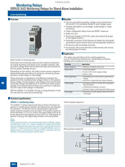
8■Overview SIRIUS 3UG46 15 monitoring relaySolid-state line monitoring relays provide maximum protection for mobile machines and plants or for unstable networks. Net-work and voltage faults can be detected early and rectified be-fore far greater damage ensues.Depending on the version, the relays monitor phase sequence, phase failure with and without N conductor monitoring, phase asymetry, undervoltage or overvoltage.Phase asymetry is evaluated as the difference between the greatest and the smallest phase voltage relative to the greatest phase voltage. Undervoltage or overvoltage exists when at least one phase voltage deviates by 20 % from the set rated system voltage or the directly set limit values are overshot or undershot. The rms value of the voltage is measured.With the 3UG46 17 or 3UG46 18 relay, a wrong direction of rota-tion can also be corrected automatically.■Benefits•Can be used without auxiliary voltage in any network from 160 to 600 V AC worldwide thanks to wide voltage range •Variably adjustable to overvoltage, undervoltage or range monitoring•Freely configurable delay times and RESET response •Width 22.5 mm•Permanent display of ACTUAL value and network fault type on the digital versions•Automatic correction of the direction of rotation by distinguish-ing between power system faults and wrong phase sequence •All versions with removable terminals•All versions with screw terminals or alternatively with innova-tive spring-type terminals■ApplicationThe relays are used above all for mobile equipment,e.g. air conditioning compressors, refrigerating containers, building site compressors and cranes.■Technical specifications3UG45 11 monitoring relaysThe 3UG45 11 phase sequenced relay monitors the phase se-quence in a three-phase network. No adjustments are required for operation. The device has an internal power supply and works using the closed-circuit principle. If the phase sequence at the terminals L1-L2-L3 is correct, the output relay picks up af-ter the delay time has elapsed and the LED is lit. If the phase se-quence is wrong, the output relay remains in its rest position.Note:When one phase fails, connected loads (motor windings, lamps, transformers, coils, etc.) create a feedback voltage at the termi-nal of the failed phase due to the network coupling. Because the 3UG45 11 relays are not resistant to voltage feedback, such a phase failure is not detected. Should this be required, then the 3UG45 12 monitoring relay must be used.Correct phase sequenceWrong phase sequenceFunction ApplicationPhase sequence •Direction of rotation of the drive Phase failure•A fuse has tripped•Failure of the control supply voltage •Broken cablePhase asymmetry•Overheating of the motor due to asymmetrical voltage•Detection of asymmetrically loaded networksUndervoltage•Increased current on a motor with correspond-ing overheating•Unintentional resetting of a device•Network collapse, particularly with battery powerOvervoltage•Protection of a plant against destruction due to overvoltage8 3UG45 12 monitoring relaysThe 3UG45 12 line monitoring relay monitors three-phase net-works with regard to phase sequence, phase failure and phaseunbalance of 10 %. Thanks to a special measuring method, aphase failure is reliably detected in spite of the wide voltagerange from 160 to 690 V and feedback through the load of up to90 %. The device has an internal power supply and works usingthe closed-circuit principle. No adjustments are required. Whenthe mains voltage is switched on, the green LED is lit. If thephase sequence at the terminals L1-L2-L3 is correct, the outputrelay picks up. If the phase sequence is wrong, the red LEDflashes and the output relay remains in its rest position. If aphase fails, the red LED is permanently lit and the output relaydrops.Note:The red LED is a fault diagnostic indicator and does not show thecurrent relay status. The 3UG45 12 monitoring relay is suitablefor line frequencies of 50/60 Hz.Phase failureWrong phase sequence3UG45 13 monitoring relaysThe 3UG45 13 line monitoring relay monitors three-phase net-works with regard to phase sequence, phase failure, phaseasymetry and undervoltage of 20 %. The device has an internalpower supply and works using the closed-circuit principle. Thehysteresis is 5 %. The integrated response delay time is adjust-able from 0 to 20 s and responds to undervoltage. If the directionis incorrect, the device switches off immediately. Thanks to aspecial measuring method, a phase failure is reliably detected inspite of the wide voltage range from 160 to 690 V and feedbackthrough the load of up to 80%. When the mains voltage isswitched on, the green LED is lit. If the phase sequence at theterminals L1-L2-L3 is correct, the output relay picks up. If thephase sequence is wrong, the red LED flashes and the outputrelay remains in its rest position. If a phase fails, the red LED ispermanently lit and the output relay drops.Note:The red LED is a fault diagnostic indicator and does not show thecurrent relay status. The 3UG45 13 monitoring relay is suitablefor line frequencies of 50/60 Hz.Phase failure and undervoltageWrong phase sequence8/6383UG46 14 monitoring relaysThe 3UG46 14 line monitoring relay has a wide voltage rangeand an internal power supply. The device is equipped with a dis-play and is parameterized using three buttons. It monitors three-phase networks with regard to phase asymetry from 5 to 20%,phase failure, undervoltage and phase sequence. The hystere-sis is adjustable from 1 to 20 V. In addition the device has a re-sponse delay and ON-delay from 0 to 20 s in each case. The in-tegrated response delay time responds to phase asymetry andundervoltage. If the direction is incorrect, the device switches offimmediately. Thanks to a special measuring method, a phasefailure is reliably detected in spite of the wide voltage range from160 to 690 V and feedback through the load of up to 80%.The 3UG46 14 monitoring relay can be operated on the basis ofeither the open-circuit or closed-circuit principle and with man-ual or auto RESET.With the closed-circuit principle selected3UG46 15/ 3UG46 16 monitoring relaysThe 3UG46 15/3UG46 16 line monitoring relay has a wide volt-age range and an internal power supply. The device is equippedwith a display and is parameterized using three buttons. The3UG46 15 device monitors three-phase networks with regard tophase failure, undervoltage, overvoltage and phase sequence.The 3UG46 16 monitoring relay monitors the neutral conductoras well. The hysteresis is adjustable from 1 to 20 V. In additionthe device has two separately adjustable delay times for over-voltage and undervoltage from 0 to 20 s in each case. If the di-rection is incorrect, the device switches off immediately. Thanksto a special measuring method, a phase failure is reliably de-tected in spite of the wide voltage range from 160 to 690 V andfeedback through the load of up to 80%.The 3UG46 15/ 3UG46 16 monitoring relay can be operated onthe basis of either the open-circuit or closed-circuit principle andwith manual or auto RESET.With the closed-circuit principle selected8/648 3UG46 17/ 3UG46 18 monitoring relaysThe 3UG46 17/ 3UG46 18 line monitoring relay has an internalpower supply and can automatically correct a wrong direction ofrotation. Thanks to a special measuring method, a phase failureis reliably detected in spite of the wide voltage range from160 to 690 V AC and feedback through the load of up to 80%.The device is equipped with a display and is parameterized us-ing three buttons. The 3UG46 17 line monitoring relay monitorsthree-phase networks with regard to phase sequence, phasefailure, phase unbalance, undervoltage and overvoltage. The3UG46 18 monitoring relay monitors the neutral conductor aswell. The hysteresis is adjustable from 1 to 20 V. In addition thedevice has delay times from 0 to 20 s in each case for overvolt-age, undervoltage, phase failure and phase unbalance. The3UG46 17/ 3UG46 18 monitoring relay can be operated on thebasis of either the open-circuit or closed-circuit principle andwith manual or auto RESET. The one changeover contact is usedfor warning or disconnection in the event of power system faults(voltage, unbalance), the other responds only to a wrong phasesequence. In conjunction with a contactor reversing assembly itis thus possible to change the direction automatically.With the closed-circuit principle selectedCircuit diagramsType3UG45 11 ... 3UG45 13, 3UG46 14 ... 3UG46 18General dataRated insulation voltage U iPollution degree 3Overvoltage category III acc. to EN 60664-1V690Rated impulse withstand voltage kV6Control circuitLoad capacity of the output relay•Conventional thermal current I th A5Rated operational current I e at•AC-15/24 ... 400 V A3•DC-13/24 V A1•DC-13/125 V A0.2•DC-13/250 V A0.1Minimum contact load at 17 V DC mA5Electrical endurance AC-15Million oper-ating cycles0.1Mechanical endurance Million oper-ating cycles103UG45 11-.A,3UG45 12-.A3UG45 11-.B, 3UG45 12-.B,3UG45 13, 3UG46 14,3UG46 15, 3UG46 173UG46 16,3UG46 18Note:It is not necessary to protect themeasuring circuit for device pro-tection. The protective device forline protection depends on thecross-section used.8/658/66*You can order this quantity or a multiple thereof.8■Selection and ordering dataPU (UNIT, SET, M)= 1PS*= 1 unit PG = 101✓ Function available -- Function not available1)Absolute limit values.2)1 CO contact each and 1 tripping delay time each for U min and U max .3)1 CO contact each for power system fault and phase sequence correction.For accessories, see page 8/90.Hysteresis Over-ON-delay Trippingdelay Rated control Screw terminalsDTSpring-type 3UG45 11-2BP203UG45 11-1AP203UG46 15-1CR203UG46 16-1CR203UG45 12-2BR203UG46 17-1CR203UG46 18-1CR208■OverviewSIRIUS 3UG46 31 monitoring relayThe relays monitor single-phase AC voltages (rms value) andDC voltages against the set threshold value for overshoot andundershoot. The devices differ with regard to their power supply(internal or external).■Benefits•Versions with wide voltage supply range•Variably adjustable to overvoltage, undervoltage or rangemonitoring•Freely configurable delay times and RESET response•Width 22.5 mm•Display of ACTUAL value and status messages•All versions with removable terminals•All versions with screw terminals or alternatively with innova-tive spring-type terminals■Application•Protection of a plant against destruction due to overvoltage•Switch-on of a plant at a defined voltage and higher•Protection against overloaded control supply voltages,particularly with battery power•Threshold switch for analog signals from 0.1 to 10V■Technical specifications3UG46 33 monitoring relaysThe 3UG46 33 voltage monitoring relay has an internal powersupply and performs overshoot, undershoot or range monitoringof the voltage depending on how it is parameterized. The deviceis equipped with a display and is parameterized using threebuttons.The operating and measuring range extends from 17 to275V AC/DC. The threshold values for overshoot or undershootcan be freely configured within this range. If one of these thresh-old values is reached, the output relay responds according tothe set principle of operation as soon as the tripping delay timehas elapsed. This delay time U Del can be set from 0.1 to 20s likethe ON-delay time on Del.The hysteresis is adjustable from 0.1 to 150V. The device can beoperated on the basis of either the open-circuit or closed-circuitprinciple and with manual or auto RESET. One output change-over contact is available as signaling contact.With the closed-circuit principle selectedOvervoltageUndervoltageRange monitoring8/6783UG46 31/ 3UG46 32 monitoring relaysThe 3UG46 31/3UG46 32 voltage monitoring relay is suppliedwith an auxiliary voltage of 24 V AC/DC or 24 to 240V AC/DCand performs overshoot, undershoot or range monitoring of thevoltage depending on how it is parameterized. The device isequipped with a display and is parameterized using threebuttons.The measuring range extends from 0.1 to 60 V or 10 to600V AC/DC. The threshold values for overshoot or undershootcan be freely configured within this range. If one of these thresh-old values is reached, the output relay responds according tothe set principle of operation as soon as the delay time haselapsed. This delay time U Del can be set from 0.1 to 20 s.The hysteresis can be set from 0.1 to 30 V or 0.1 to 300 V. Thedevice can be operated on the basis of either the open-circuit orclosed-circuit principle and with manual or auto RESET. One out-put changeover contact is available as signaling contact.With the closed-circuit principle selectedOvervoltageUndervoltageRange monitoringCircuit diagrams3UG46 313UG46 323UG46 33 General dataRated insulation voltage U iPollution degree 3Overvoltage category III acc. to EN 60664-1V690Rated impulse withstand voltage U imp kV6Measuring circuitPermissible measuring range single-phase AC/DC voltage V0.1 ... 6810 ... 65017 (275)Setting range single-phase voltage V0.1 ... 6010 ... 60017 (275)Measuring frequency Hz40 (500)Control circuitLoad capacity of the output relay•Conventional thermal current I th A5Rated operational current I e at•AC-15/24 ... 400 V A3•DC-13/24 V A1•DC-13/125 V A0.2•DC-13/250 V A0.1Minimum contact load at 17 V DC mA53UG46 31-.AA30,3UG46 32-.AA303UG46 31-.AW30,3UG46 32-.AW303UG46 33Note:It is not necessary to protect themeasuring circuit for deviceprotection. The protective devicefor line protection depends on thecross-section used.8/688/69*You can order this quantity or a multiple thereof.8■Selection and ordering data•Digitally adjustable, with illuminated LC display •Auto or manual RESET•Open or closed-circuit principle •1 CO contactPU (UNIT, SET, M)= 1PS*= 1 unit PG = 101Absolute limit values.For accessories, see page 8/90.Measuring rangeHysteresis3UG46 31-1AA303UG46 33-2AL30。

专利名称:Detection apparatus, detection method, andelectronic apparatus发明人:Kurihara, Kazuo申请号:EP08009036.8申请日:20080515公开号:EP1995556A2公开日:20081126专利内容由知识产权出版社提供专利附图:摘要:A detection apparatus includes: a cantilever vibration gyro including apiezoelectric element having a first side provided with a drive electrode and a pair of detection electrodes sandwiching the drive electrode with predetermined gapstherebetween and a second side opposed to the first side and provided with a common electrode, which vibrates by a drive signal input between the drive electrode and the common electrode and generates a pair of detected signals corresponding to Coriolis force from the detection electrodes; a bias applying section applying a bias voltage to the detection electrodes; an adding section adding the pair of detected signals; a first phase delay section delaying a phase of the detected signal obtained by the addition by a range larger than 45° and smaller than 90°; and an amplitude control section controlling the delayed detected signal to a predetermined voltage amplitude to output as the drive signal.申请人:Sony Corporation地址:1-7-1 Konan, Minato-ku Tokyo JP国籍:JP代理机构:Müller - Hoffmann & Partner更多信息请下载全文后查看。
第28卷㊀第4期2024年4月㊀电㊀机㊀与㊀控㊀制㊀学㊀报Electri c ㊀Machines ㊀and ㊀Control㊀Vol.28No.4Apr.2024㊀㊀㊀㊀㊀㊀多时间尺度小波变换和LSTM 自编码器电弧故障检测方法邱婷婷,㊀曹文平,㊀刘孝宇,㊀漆星(安徽大学电气工程与自动化学院,安徽合肥230001)摘㊀要:在光伏发电系统中,电弧故障检测是维持系统安全运行的关键问题㊂以往的电弧故障检测方法大多基于单时间尺度的故障特征,然而单一时间尺度特征往往会受到环境变化的干扰,导致检测精度降低,针对这一问题,提出一种多时间尺度小波和长短时记忆(LSTM )自编码器电弧故障检测方法,该方法首先在机理分析的基础上找到电弧3个特性,即电弧初始阶段电流发生突变㊁燃弧阶段电流均值降低㊁燃弧阶段高频分量变大㊂再基于上述电弧特性进行小波变换提取对应多尺度特征,然后使用LSTM 自编码器进行端到端的自动检测㊂与以往方法不同,该方法提取了电弧特性的多种时间尺度特征,增加了故障信号的检测依据,降低了受外界干扰时检测结果出现误报漏报的可能性㊂理论分析和实验结果表明,所提出的方法降低了故障电弧检测的误报率,提高了其准确率㊂关键词:光伏发电;电弧故障;单类;小波变换;长短时记忆自编码器;多时间尺度特征DOI :10.15938/j.emc.2024.04.015中图分类号:TM501文献标志码:A文章编号:1007-449X(2024)04-0139-10㊀㊀㊀㊀㊀㊀㊀㊀㊀㊀㊀㊀㊀㊀㊀㊀㊀㊀㊀㊀㊀㊀㊀㊀㊀㊀㊀㊀㊀㊀㊀㊀㊀㊀㊀㊀㊀㊀㊀㊀㊀㊀㊀㊀㊀㊀㊀㊀㊀㊀㊀㊀㊀㊀㊀㊀㊀㊀㊀㊀㊀㊀㊀㊀㊀㊀㊀㊀㊀㊀㊀㊀㊀㊀㊀㊀㊀㊀㊀㊀㊀㊀㊀㊀㊀㊀㊀㊀㊀㊀㊀㊀㊀㊀㊀㊀㊀㊀㊀㊀㊀㊀㊀㊀㊀㊀㊀㊀㊀㊀㊀㊀收稿日期:2022-08-31基金项目:科技合作专项-国际科技合作项目(2022h11020023)作者简介:邱婷婷(1999 ),女,硕士研究生,研究方向为光伏逆变器电弧故障诊断;曹文平(1969 ),男,博士,教授,博士生导师,研究方向为电机与电气故障诊断;刘孝宇(1999 ),男,硕士,研究方向为光伏逆变器电弧故障诊断;漆㊀星(1985 ),男,博士,讲师,研究方向为机器学习算法故障诊断㊂通信作者:曹文平Multi time scale wavelet transform and LSTM autoencoderarc fault detection methodQIU Tingting,㊀CAO Wenping,㊀LIU Xiaoyu,㊀QI Xing(School of Electrical Engineering and Automation,Anhui University,Hefei 230001,China)Abstract :In the photovoltaic power generation system,arc fault detection is the key to maintain the safeoperation of the system.Most of the previous arc fault detection methods are based on the fault features of single time scale.However,the single time scale features are often disturbed by environmental changes,resulting in the reduction of detection accuracy.To solve this problem,a multi time scale wavelet and long-short memory(LSTM)autoencoder arc fault detection method was proposed.Firstly,on the basis ofmechanism analysis,the method finds three characteristics of the arc,namely,the sudden change of cur-rent in the initial stage of the arc,the average value of current in the arcing stage decreases and the high frequency component in the arcing stage increases;Based on the above arc characteristics,wavelet trans-form was performed to extract the corresponding multi-scale features,and then LSTM self-encoder wasused for end-to-end automatic detection.Unlike the previous methods,this method extracts the multi-time scale features corresponding to the arc characteristics,which increases the detection basis of the faultsignal and reduces the possibility of false alarm and missing alarm in the detection result when the fault signal is interfered by the outside.Theoretical analysis and experimental results show that the proposed method reduces the false alarm rate of fault arc detection and improves its accuracy. Keywords:photovoltaic power generation;arc fault;one-class;wavelet transform;long-short memory utoencoder;multi-time scale features0㊀引㊀言光伏发电是清洁能源的重要研究领域,检测光伏逆变器的直流故障电弧是保障光伏发电系统安全有效工作的重点之一㊂直流故障电弧一般可分为串联型㊁并联型以及接地型[1-3],其中串联型故障电弧检测是研究重点,当光伏系统发生直流串联电弧故障时,负载电流会减小,相较于另外两种电弧更难被过电流保护装置检测到[4-5],从而容易导致火灾等重大事故的发生㊂针对直流串联型电弧故障,传统方法可以分为基于时频域检测方法和基于物理特性检测方法这两大类㊂基于时频域检测方法是通过故障电弧电流㊁电压的时频域特征对电弧进行检测㊂例如,SEO G S利用快速傅里叶变换(fast Fourier transform,FFT)提取电弧频率特征进行检测故障电弧[6],WANG Z 与BALOG R S利用小波变换实现对故障电弧信号的多分辨率分析,从而利用捕捉的特性对故障电弧进行检测[7]㊂这类方法可以提取到故障电弧的明显特征,但是最终检测结果往往需要人员亲自判断,增加了人力负担㊂另一类基于物理特性的检测方法是通过故障电弧的电磁辐射㊁弧光和噪声等物理特征来构建检测系统,例如KIM C J利用棒形天线和环形天线获取电弧的电磁辐射信号,从而进行检测电弧故障[8],YUVENTI J使用希尔伯特分形天线捕捉直流电弧的高频电磁辐射,然后检测电弧故障[9],这类方法可解释性强,但其往往只能检测固定位置的电弧故障且检测结果易受环境影响㊂近年来,随着机器学习理论的兴起,很多学者采用基于机器学习理论进行直流串联型故障电弧诊断方法的研究㊂相比于传统方法,机器学习的方法具有端到端的优势,其检测的最终结果不会受到人为因素的影响㊂例如,LU S提出基于领域自适应和深度卷积生成对抗网络(domain adaptive-deep convolu-tional generative adversarial networks,DA-DCGAN)的方法检测电弧故障[10]㊂PATIL D D提出基于电压特征利用卷积神经网络(convolutional neural net-work,CNN)进行故障电弧识别[11]㊂然而,这些方法通常只针对信号的单一时间尺度特征进行分析研究,而在实际工程中,单一时间尺度的特征往往会受到外部环境的干扰,进而影响最终的检测结果㊂为了解决单一时间尺度特征导致的误报和漏报问题,本文提出一种基于多时间尺度小波变换长短时记忆(long-short memory,LSTM)自编码器的单类重构算法,进行直流串联型故障电弧的检测㊂首先通过机理分析找到电弧电流3个特性:1)电弧初始阶段电流发生突变;2)燃弧阶段电流均值降低;3)燃弧阶段高频分量变大[12]㊂再基于上述电弧特性通过一组高通和低通滤波器提取对应的多时间尺度特征,然后利用LSTM自编码器模型重构多时间尺度特征,最后根据重构误差进行判断该测试数据是否为故障电弧信号㊂通常,传统方法大多基于电弧某单一时间尺度特性进行故障检测,当光伏系统受到外界因素影响时,可能会造成检测结果的误判或漏判㊂相比较而言,该方法基于电弧特性的理论分析,选取多个时间尺度作为信号特征,能够增加检测的判断依据,提高检测精度,降低误报率,并且实现端到端的自动检测㊂1㊀光伏故障电弧机理分析本节首先分析总结电弧电流的一般特性,然后采集光伏系统中两种最常见的干扰电弧检测情况的电流信号,并分析讨论基于单一时间尺度特征检测故障电弧的缺陷㊂1.1㊀电弧特性分析电弧是气体放电中的自持放电,属于低温等离子体[13]㊂理论研究表明,电弧在不同发展阶段其电流会表现出不同的时间尺度特性,具体分析如下: 1)初始阶段发生突变㊂电弧初始阶段电流会发生突变㊂电爆炸电流电压变化如图1所示,电流突然降低后又迅速上升,并出现振荡现象,这是因为在两极间发生电爆炸产生等离子体过程中,其相应电阻先变大后又减小[14-15],又因所产生的等离子体并不稳定,电流出现振荡现象㊂041电㊀机㊀与㊀控㊀制㊀学㊀报㊀㊀㊀㊀㊀㊀㊀㊀㊀㊀㊀㊀㊀第28卷㊀图1㊀电爆炸电流电压变化Fig.1㊀Electric explosion current and voltage change2)燃弧阶段均值降低㊂电弧稳定燃烧阶段电流会出现均值降低现象,可将电弧等效为一个非线性电阻,直流故障电弧等效电路原理图如图2所示㊂当电弧产生后,电弧电阻出现,回路总电阻增大,回路电流减小[16-17]㊂图2㊀直流故障电弧等效电路Fig.2㊀DC fault arc equivalent circuit3)燃弧阶段高频分量变大㊂电弧稳定燃烧阶段,电流同时也会出现高频分量变大现象,如图3所示㊂电弧燃烧阶段不仅会发生碰撞电离和热电离,使间隙中持续产生带电粒子,而且也发生带电粒子的复合等去游离过程,其外部表现为电流的持续波动,反映在频域上就是高频分量增大[12]㊂由上述分析可知,故障电弧电流存在以下3个特性:电弧发生初始阶段发生突变㊁电弧燃烧阶段出现均值降低以及高频分量变大现象㊂值得注意的是,从图1可知电爆炸过程属于纳秒级别,一般无法通过AD 采样芯片采集,因此在实际工程中使用均值降低和高频分量变大两个特性检测故障电弧,图3为光伏系统发生电弧时的电流信号㊂图3㊀故障电弧电流信号Fig.3㊀Fault arc current signal1.2㊀基于单一时间尺度特征检测故障电弧的缺陷实际电弧故障检测工程中,当光伏系统受外界干扰时,其电流会产生与上述电弧电流某一时间尺度特性类似的情况,因此只使用单一时间尺度特征可能会造成检测结果的误判㊂最为常见的情况有2种,例如:图4是光照强度降低时电流出现均值降低的情况,通常受光照强度干扰增加的是1Hz 以下的频率分量[12],因此与电弧故障情况不同的是,该情况受干扰前后电流信号的高频分量没有明显变化;图5是受电网波动干扰时电流出现高频分量变大的情况[18],与电弧故障情况不同的是,该情况受干扰前后电流信号的均值基本保持不变㊂图4㊀光照强度降低时电流信号Fig.4㊀Current signal when sunlightdecreases图5㊀受电网干扰时电流信号Fig.5㊀Current signal when disturbed by power grid综上所述,在故障电弧检测中如果只使用单一尺度特征进行判断,很难将发生故障电弧情况与其他受干扰情况进行区分,从而使检测结果产生误报㊂2㊀多时间尺度小波-LSTM 自编码器故障电弧检测方法㊀㊀为解决上述单一尺度特征问题,本文基于多时间尺度小波-LSTM 自编码器方法检测故障电弧,该方法基于电弧电流的均值降低以及高频分量变大特性,利用小波变换提取对应多时间尺度特征,增加检测的判断依据,并且使用LSTM 自编码器实现端到端自动检测㊂本文方法包含3个部分,分别为:1)利用小波变换提取多尺度特征;2)使用LSTM 自编码器重构获得重构误差;3)通过决策策略输出判断结果,方法框架如图6所示㊂141第4期邱婷婷等:多时间尺度小波变换和LSTM 自编码器电弧故障检测方法图6㊀方法框架Fig.6㊀Framework of method2.1㊀利用小波变换提取多尺度特征由第1节可知,检测故障电弧可依据电弧稳定燃烧阶段的均值降低以及高频分量变大特性㊂本文依据上述电弧特性使用多尺度小波变换提取电弧电流的特征,将原始数据进行标准化,其中标准化公式为I nor=i raw -u s㊂(1)式中:I nor 为标准化后的数据;i raw 为原始数据;u 为均值;s 为标准差㊂接着将标准化后的数据进行离散小波变换[19],即利用正交小波基将信号分解为不同尺度下的各个分量,其实现过程相当于重复使用一组高通和低通滤波器,对信号逐步分解,最终得到不同尺度下的细节系数cD i 和逼近系数cA i ,如图7所示,图中h 0和h 1分别代表高通和低通滤波器系数[20]㊂设信号长度为m ,滤波器长度为k ,则第i 层小波变换的近似系数和细节系数为:a i [m ]=ðK -1K =0a i -1[2m -k ]h 1[k ];d i [m ]=ðK -1K =0d i -1[2m -k ]h 0[k ]㊂üþýïïï(2)图7㊀离散小波变换示意图Fig.7㊀Schematic diagram of discrete wavelet transform一般检测方法使用小波变换提取故障电弧特征时只考虑高频分量变大特性,仅提取较高频段特征作为检测依据,因此可能会出现误报㊁漏报的现象,本文加入均值降低特性作为检测依据,使得故障检测更加全面,提高了检测结果的精度㊂同时,为使故障信号的多尺度特征与正常信号区分更为明显,采用五级离散小波变换, db4 作为小波基进行分解电弧信号,选取cA5以及cD4作为电弧信号的尺度特征,cA5特征为低频段对应于均值降低特性,cD4特征为高频段对应于高频分量变大特性㊂2.2㊀使用LSTM 自编码器重构获得重构误差使用小波变换后所提取的特征输入LSTM 自编码器模型进行重构,该模型可在考虑时序因素的情况下处理序列的前后联系,并实现端到端输出㊂首先利用给定的训练数据X 的特征训练LSTM 自编码器㊂图8为LSTM 自编码器结构图,该模型采用了LSTM 作为神经网络结构单元,其总体包括编码器和解码器两部分,编码器将高维输入数据映射到低维抽象表示,实现数据的特征提取,解码器则将抽象表示转换为期望输出,实现输入数据的重构㊂图8㊀LSTM 自编码器结构图Fig.8㊀LSTM autoencoder structure模型中的LSTM 含有输入门i t ㊁更新门c t ㊁遗忘门f t ㊁输出门o t[21-22],其结构图如图9所示㊂图9㊀LSTM 结构图Fig.9㊀LSTM structure数据首先通过遗忘门丢弃某些信息,其输入为当前时刻t 的输入x t 与上一时刻t -1的输出h t -1,表达式为f t =σ(W f [h t -1,x t ]+b f )㊂(3)241电㊀机㊀与㊀控㊀制㊀学㊀报㊀㊀㊀㊀㊀㊀㊀㊀㊀㊀㊀㊀㊀第28卷㊀式中:W f 表示遗忘门的权重系数矩阵;b f 表示遗忘门的偏置向量㊂输入门输入当前信息,用于决定向结构单元中添加信息的量,同时利用tanh 层创建候选向量用于当前输入的单元状态:㊀㊀i t =σ(W i [h t -1,x t ]+b i );(4)㊀㊀C ~t =tanh(W c [h t -1,x t ]+b c )㊂(5)式中:W i 表示输入门的权重系数矩阵;b i 表示输入门的偏置向量㊂其次,需要将上一个状态值C t -1更新为C t ,对记忆单元的信息进行更新,即C t =f t C t -1+i t C ~t ㊂(6)最后,通过输出门输出隐藏变量:㊀㊀㊀o t =σ(W o [h t -1,x t ]+b o );(7)㊀㊀㊀h t =o t tanh(C t )㊂(8)式中:σ为sigmoid 激活函数;tanh 为双曲正切激活函数㊂σ和tanh 的表达式为:σ=11+e -x;㊀㊀㊀㊀(9)tanh =sinh(x )cosh(x )=1-e -2x1+e -2x㊂(10)接着,利用训练后的模型重构测试数据O 的多尺度特征,最终得到O ᶄ=(cA5ᶄ,cD4ᶄ)㊂接着利用下式求每组各特征向量各点的重构误差:L n [j ][k ]=(O n [j ][k ]-O ᶄn [j ][k ])2㊂(11)式中:O n [j ][k ]表示第n 组序列的第j 个特征向量的第k 个点原数据;O ᶄn[j ][k ]表示第n 组序列的第j个特征向量的第k 个点的重构数据;L n [j ][k ]表示第n 组序列的第j 个特征向量的第k 个点的重构误差㊂最后,设置阈值求每组各特征向量的误差统计值㊂设变量e nj 为第n 组序列的第j 个特征向量的统计误差值,初始化e nj =0,计算e nj 的过程为:如设置阈值为2,当L n [j ][k ]ȡ2时,e nj 计数加一,遍历整个第n 组序列,得到e nj 的最终数值㊂2.3㊀通过决策策略输出判断结果利用所获得的e n 1㊁e n 2判断第n 组序列是否为电弧故障信号㊂经多次实验总结,本文判断第n 组序列的电流信号是否故障的公式为:S =1,if e n 1>2e x 1and e n 2>2e x 2;0,if en 1<2e x 1or e n 2<2e x 2㊂{(12)式中:S =1表示最终结果输出1,即该序列判断为故障电弧信号;S =0表示最终结果输出0,即该序列判断为正常信号;e x 1㊁e x 2表示训练数据的误差统计值㊂3㊀光伏故障电弧实验验证3.1㊀实验平台本文参照UL1699B 标准搭建实验平台,其工作电流为10A,工作电压为300V㊂实验平台中的电流信号采集部分所使用控制芯片为TI 公司的T280049C 系列,其采样频率为128kHz㊂所使用的电弧发生器由2个铜棒以及1个步进电机组成,步进电机通过拉动铜棒控制电弧的产生,图10为利用电弧发生器产生电弧的情景㊂同时本文通过Python 语言进行实验验证,模型采用Keras [23]框架㊂图10㊀实验平台产生的电弧Fig.10㊀Electric arc generated by the test platform3.2㊀使用小波进行多时间尺度特征提取本节展示了一段电弧故障电流信号并将其作为实验的测试数据,然后利用小波变换提取一段故障电弧电流的多尺度特征,作为电弧故障检测的判断依据㊂图11展示的是一段700ms 的故障电弧信号,共有89600个采样点,分为14组测试序列,一组测试序列含有6400个采样点㊂图11㊀故障电弧电流Fig.11㊀Fault arc current图12(a)㊁图12(b)分别为一段故障电弧电流信号经五级离散小波变换获得的特征cA5㊁特征cD4㊂可以看出,燃弧阶段的特征cA5均值小于未341第4期邱婷婷等:多时间尺度小波变换和LSTM 自编码器电弧故障检测方法发生电弧阶段,燃弧阶段的特征cD4幅值大于未发生电弧阶段㊂图12㊀故障电弧电流特征Fig.12㊀Fault arc current features3.3㊀端到端最终检测结果本节依据3.2节所提取的故障电弧电流多尺度特征,使用LSTM 自编码器以及决策策略进行端到端的自动检测㊂图13(a)为每组序列的特征cA5㊁cD4进行重构后所对应获得的误差统计值e n 1㊁e n 2,观察分析可知,发生电弧的电流数据的e n 1㊁e n 2比未发生电弧的电流数据的普遍要大,这个结果符合上述对故障电弧信号各特征的特点总结㊂最后,利用决策策略依据{e n 1,e n 2}对各组测试序列进行判断并直接输出检测结果,如图13(b)所示,检测结果为0代表检测该序列为正常信号,检测结果为1代表检测该序列电弧信号,可以看出其检测结果全部正确㊂图13㊀电弧故障检测实验结果Fig.13㊀Experimental results of arc fault detection3.4㊀电弧故障检测中两种常见干扰情况检测结果为分析该方法在实际电弧故障检测工程中误报率的优劣性,本节使用本文方法针对两种最为常见的干扰情况进行检测实验:实验一为阳光强度降低的情况,本文通过电流突变实验模拟并获取该情况下的电流信号;实验二为受电网波动干扰的情况,本文通过并网接入大功率感性器件模拟电网波动现象,以获取该情况下的电流信号㊂实验一:阳光强度降低㊂图14为阳光强度降低时电流信号均值降低的情况,该段信号时长700ms,共有89600个采样点,分为14组测试序列,一组测试序列含有6400个采样点㊂图14㊀阳光强度降低时电流Fig.14㊀Current when sunlight decreases图15(a)㊁图15(b)分别为一段阳光强度降低时的电流信号经五级离散小波变换得到的特征cA5㊁特征cD4㊂可以看出,阳光强度变化前的特征cA5的均值小于阳光强度变化后,阳光强度变化前与阳光强度变化后的特征cD4无明显区别㊂图15㊀阳光强度降低时电流特征Fig.15㊀Current features when sunlight decreases图16(a)为每组数据的特征cA5㊁cD4进行重构后所对应获得的误差统计值e n 1㊁e n 2,观察分析可知,阳光强度变化前的e n 1比阳光强度变化后的电流数441电㊀机㊀与㊀控㊀制㊀学㊀报㊀㊀㊀㊀㊀㊀㊀㊀㊀㊀㊀㊀㊀第28卷㊀据的普遍要大,但阳光强度变化前的e n 2与阳光强度变化后的无明显差别㊂最后利用决策策略判断的结果如图16(b)所示,检测结果为0代表检测该序列为正常信号,检测结果为1代表检测该序列电弧信号,结果表明,本文方法不会对电流信号受到干扰而均值降低的情况产生误报㊂图16㊀阳光强度降低时检测故障实验结果Fig.16㊀Experimental results of fault detection whensunlight decreases实验二:受电网波动干扰㊂图17为受到电网波动干扰时电流信号高频分量增加的情况,该段信号时长700ms,共有89600个采样点,分为14组测试序列,一组测试序列含有6400个采样点㊂图17㊀受电网波动干扰时电流Fig.17㊀Current when disturbed by power gridfluctuation图18(a)㊁图18(b)分别为一段受电网干扰时的电流信号经五级离散小波变换得到的特征cA5㊁特征cD4,可以看出,受电网干扰前与受电网干扰后的特征cA5无明显区别,而受电网干扰后的特征cD4幅值大于受电网干扰前的㊂图19(a)为每组数据的特征cA5㊁cD4进行重构后所对应获得的误差统计值e n 1㊁e n 2,观察分析可知,受电网干扰前的e n 1与受电网干扰后的无明显差别,而受电网干扰后的e n 2普遍大于受电网干扰前的㊂最后利用决策策略判断的结果如图19(b)所示,检测结果为0代表检测该序列为正常信号,检测结果为1代表检测该序列电弧信号,结果表明,本文方法不会对电流信号受到干扰而高频分量增加的情况产生误报㊂图18㊀受电网干扰时电流特征Fig.18㊀Current features when disturbed by powergrid图19㊀受电网干扰时检测实验Fig.19㊀Detection experiment when disturbed bypower grid4㊀比较实验本节使用典型的单尺度方法:FFT [5]方法和CNN [10]方法,作为与本文方法进行比较的基线方法㊂为对比分析各方法的检测效果,每种方法在3种典型工况下各进行50组故障检测模拟实验,并使用统计学中的误差棒图分析实验结果㊂最后设置比较指标,利用统计学中的均值和标准误差作为最终评估结果㊂541第4期邱婷婷等:多时间尺度小波变换和LSTM 自编码器电弧故障检测方法4.1㊀3种方法实验结果的比较电弧故障检测中通常包含3种典型工况,分别为发生电弧和3.4节中所示的阳光强度降低以及电网波动干扰㊂利用FFT 方法㊁CNN 方法和本文方法针对3种典型工况各做50组实验,每组实验包含14组测试序列,序列检测结果输出0或1,输出0表示检测该序列为正常信号,输出1表示检测该序列电弧信号㊂最后,采用误差棒统计图分析3种工况下各方法50组实验的检测结果,如图20~图22所示㊂1)发生电弧㊂图20(a)为该工况下一组实验的测试数据,分为14组测试序列㊂图20(b )~图20(d)为该工况下3种方法的50组实验结果统计图,可以看出,3种方法在未发生电弧阶段无误报情况,在燃弧阶段产生漏报的可能性都不高,但相比较而言本文方法产生漏报的可能性最低㊂图20㊀发生电弧时3种方法50组检测结果的统计Fig.20㊀Statistics of 50groups of detection results ofthree methods when arc occurs2)阳光强度降低㊂图21(a)为该工况下一组实验的测试数据,分为14组测试序列㊂图21(b)~图21(d)为该工况下3种方法的50组实验结果统计图,可以看出,3种方法在阳光强度变化前无误报情况,CNN 方法在阳光强度降低后产生误报的可能性最大,FFT 方法和本文方法没有产生误报㊂图21㊀阳光强度降低时3种方法50组检测结果的统计Fig.21㊀Statistics of 50groups of detection results bythree methods when sunlight decreases3)受到电网波动干扰㊂图22(a)为该工况下一组实验的测试数据,分为14组测试序列㊂图22(b)~图22(d)为该工况下3种方法的50组实验结果统计图,可以看出,受电网波动干扰后FFT 方法出现误报的可能性最大,本文方法出现误报的可能性最低㊂4.2㊀比较指标及评估结果为对比分析FFT 方法㊁CNN 方法和本文方法检测故障电弧的准确性,采用准确率(accuracy,641电㊀机㊀与㊀控㊀制㊀学㊀报㊀㊀㊀㊀㊀㊀㊀㊀㊀㊀㊀㊀㊀第28卷㊀ACC)㊁假阳性率(false positive rate,FPR)和假阴性率(false negative rate,FNR)指标进行评估㊂图22㊀受电网波动干扰时3种方法50组检测结果的统计Fig.22㊀Statistics of 50groups of detection results bythree methods when disturbed by power gridACC 用于评估检测精度,该指标数据越高表明方法的检测准确率越高,其表达式为ACC =T P +T NT P +T N +F P +F N㊂(13)FPR 用于评估检测的误报率,该指标数据越低表明方法出现误报的可能性越小,其表达式为FPR =F PT N +F P㊂(14)FNR 用于评估检测的漏报率,该指标数据越低表明方法出现漏报的可能性越小,其表达式为FNR =F NT P +F N㊂(15)式中T P ㊁T N ㊁F P ㊁F N 分别为真阳性㊁真阴性㊁假阳性㊁假阴性样本个数㊂经过3种工况下的各50组模拟检测实验,利用上述比较指标的均值和标准误差评估3种方法检测故障电弧的准确性,如表1所示㊂表1㊀50组模拟检测实验结果Table 1㊀50groups of simulated test results指标FFT 方法CNN 方法本文方法ACC 0.860ʃ0.0800.910ʃ0.0600.960ʃ0.020FPR0.150ʃ0.0300.100ʃ0.0200.040ʃ0.004FNR 0.040ʃ0.0050.030ʃ0.0050.010ʃ0.001实验结果表明,FFT 方法以及CNN 方法由于只使用了故障电弧的单一尺度特征作为检测依据,当光伏系统受到干扰时产生误报的可能性会更大,尤其当受到电网波动干扰时,由于FFT 方法是基于信号高频特征进行判断检测,所以该种情况下误报率较高㊂而本文方法提取了多时间尺度特征作为电弧检测模型输入,增加了判断依据,使得检测结果更加精准,明显降低了误报率㊂5㊀结㊀论针对光伏系统的直流串联型电弧故障检测问题,本文提出一种基于多时间尺度小波变换LSTM 自编码器单类重构算法检测方法,首先利用多时间尺度小波变换对光伏系统逆变器直流侧的电流信号进行特征提取,然后将多时间尺度特征作为LSTM 自编码器模型的输入进行端到端自动检测㊂理论分析和实验结果表明,相比于传统检测方法只提取单一时间尺度作为信号特征,本文方法在电弧机理分析的基础上,选取对应电弧特性的多时间尺度作为信号特征,使得检测的判断依据更加全面,提高了检测精度,降低了检测结果受外界干扰的可能性,减少了误报率和漏报率㊂参考文献:[1]㊀VELASCO QUESADA G,GUINJOAN GISPERT F,PIQUE LOP-EZ R,et al.Electrical PV array reconfiguration strategy for energy extraction improvement in grid-connected PV systems [J].IEEE Transactions on Industrial Electronics,2009,56(11):4319.[2]㊀XIONG Qing,JI Shengchang,ZHU Lingyu,et al.A novel DC arcfault detection method based on electromagnetic radiation signal [J].IEEE Transactions on Plasma Science,2017,45(3):472.[3]㊀YAO X,HERRERA L,JI S,et al.Characteristic study and time-741第4期邱婷婷等:多时间尺度小波变换和LSTM 自编码器电弧故障检测方法。
AUTO AFTERMARKET | 汽车后市场纯电动汽车绝缘检测方法及维修案例分析王昕灿1 李京鑫2 翟羽1 王震1 王贺11.江苏航运职业技术学院 江苏省南通市 2260102.马鞍山职业技术学院 安徽省马鞍山市 243031摘 要: 绝缘性是纯电动汽车高压安全性能中的主要指标之一,在进行纯电动汽车检测与维修过程中,对高压电气系统的绝缘性能检测需要使用专用的绝缘测试仪器,测量高压电缆及高压部件对车身绝缘电阻是否位于规定值范围内。
分析绝缘检测原理和绝缘电阻检测方法,并以奇瑞eQ1纯电动汽车绝缘故障为例,进一步剖析绝缘检测方法和注意事项,为新能源汽车的检测和维护提供安全保障。
关键词:纯电动汽车 绝缘检测 维修 安全1 引言纯电动汽车动力系统一般具有直流300V以上的工作电压,其主要包括驱动电机及控制器、高压动力电池及电池管理系统、高压控制盒、逆变器总成及其他电力电子设备[1]。
因此相对较高的车辆运行电压对纯电动汽车高压动力系统和整车底盘间的绝缘性能提出了更为严格的要求。
车辆动力传输系统中高压动力电缆的绝缘层往往会因受环境潮湿影响绝缘性,或者绝缘层老化干裂导致绝缘性能下降,从而易导致动力系统电源高压导线透过绝缘层介质与整车底盘结构形成电路回路,造成高压电路短路、底盘电位整体上升,危害性极大。
这些危害会造成驾驶人员、乘坐人员以及维修人员的人身安全,同时也将在一定程度上影响车辆控制线路、信号线路以及其他低压电路的正常工作。
当车辆高压系统与底盘间多处连接点间的绝缘性能严重下降,更会造成漏电短路,产生热积效应,最重要的情况下甚至会造成整车电气火灾。
因此,保障纯电动汽车的绝缘性能是保证车辆安全性的重要工作之一,通过准确实时监测高压系统对底盘的绝缘性,包括驱动电机系统绝缘性、动力电池系统绝缘性等,可以及时排查并解决车辆的绝缘故障,保证车辆设备正常运作和汽车安全运行。
在新能源汽车检测与维修过程中,对于绝缘性能的好坏一般通过被测物绝缘电阻的大小来判定。
第27卷㊀第12期2023年12月㊀电㊀机㊀与㊀控㊀制㊀学㊀报Electri c ㊀Machines ㊀and ㊀Control㊀Vol.27No.12Dec.2023㊀㊀㊀㊀㊀㊀基于开口变压器法的交流电机定子铁心短路故障检测武玉才1,㊀张龙1,㊀白雨卉1,㊀马明晗1,㊀赵海森2,㊀许国瑞2(1.华北电力大学河北省绿色高效电工新材料与设备重点实验室,河北保定071003;2.华北电力大学电气与电子工程学院,北京102206)摘㊀要:为了简便㊁可靠地检测和定位交流电机定子铁心叠片的片间短路故障,缩短机组维修和停运时间,提出利用开口变压器法检测交流电机定子铁心故障的方法㊂首先推导定子铁心正常和叠片片间短路故障情况下开口变压器铁心的磁通特征,进一步得到开口变压器感应电压的表达式,预测了片间短路故障的感应电压特征㊂然后以一台QFSN -300-2型汽轮发电机定子作为研究对象,通过二维有限元电磁模型进行仿真验证,进一步在一台小型异步电机定子铁心上进行实验验证㊂仿真和实验结果表明:在定子铁心正常情况下,开口变压器线圈在定子铁心各槽的感应电压都很小;当定子铁心某槽发生片间短路时,开口变压器线圈在该槽的感应电压随之升高,并且感应电压的幅值随着故障位置和故障程度不同而有所差异,证明了开口变压器法可用于检测交流电机定子铁心叠片片间短路故障㊂关键词:开口变压器法;交流电机;定子铁心;片间短路;感应电压;故障诊断DOI :10.15938/j.emc.2023.12.003中图分类号:TM34文献标志码:A文章编号:1007-449X(2023)12-0021-10㊀㊀㊀㊀㊀㊀㊀㊀㊀㊀㊀㊀㊀㊀㊀㊀㊀㊀㊀㊀㊀㊀㊀㊀㊀㊀㊀㊀㊀㊀㊀㊀㊀㊀㊀㊀㊀㊀㊀㊀㊀㊀㊀㊀㊀㊀㊀㊀㊀㊀㊀㊀㊀㊀㊀㊀㊀㊀㊀㊀㊀㊀㊀㊀㊀㊀㊀㊀㊀㊀㊀㊀㊀㊀㊀㊀㊀㊀㊀㊀㊀㊀㊀㊀㊀㊀㊀㊀㊀㊀㊀㊀㊀㊀㊀㊀㊀㊀㊀㊀㊀㊀㊀㊀㊀㊀㊀㊀㊀㊀㊀㊀㊀㊀㊀㊀收稿日期:2023-03-15基金项目:国家自然科学基金(52277048);河北省自然科学基金(E2023502002)作者简介:武玉才(1982 ),男,博士,副教授,博士生导师,研究方向为大型电气设备状态监测与故障诊断;张㊀龙(1996 ),男,硕士研究生,研究方向为大型电气设备状态监测与故障诊断;白雨卉(1999 ),女,硕士研究生,研究方向为大型电气设备状态监测与故障诊断;马明晗(1990 ),男,博士,讲师,研究方向为电气设备状态监测与故障诊断;赵海森(1982 ),男,博士,教授,博士生导师,研究方向为高效低振动电机理论研究与设计㊁无线电能传输等;许国瑞(1986 ),男,博士,副教授,博士生导师,研究方向为大型发电机多物理场分析㊁机网协调运行以及新型发电机㊁调相机㊂通信作者:武玉才Short circuit fault detection of AC motor stator core based onopen transformer methodWU Yucai 1,㊀ZHANG Long 1,㊀BAI Yuhui 1,㊀MA Minghan 1,㊀ZHAO Haisen 2,㊀XU Guorui 2(1.Key Laboratory of Green and Efficient New Electrical Materials and Equipment in Hebei Province,North China ElectricPower University,Baoding 071003,China;2.College of Electrical and Electronic Engineering,North China ElectricPower University,Beijing 102206,China)Abstract :In order to detect and locate the inter-chip short-circuit fault of AC motor stator core lamina-tions simply and reliably,and shorten the maintenance and shutdown time of the unit,a method for de-tecting the fault of AC motor stator core by using the open transformer method was proposed.Firstly,the magnetic flux characteristics of the open-end transformer core under normal stator core and laminated in-ter-chip short-circuit fault were derived.The expression of the induced voltage of the open-end transform-er was further obtained,and the induced voltage characteristics of the inter-chip short-circuit fault werepredicted.Then,a QFSN -300-2type turbine generator stator was taken as the research object,andthe simulation verification was carried out by the two-dimensional finite element electromagnetic model,and the experimental verification was further carried out on the stator core of a small asynchronous motor.The simulation and experimental results show that under the normal condition of the stator core,the in-duced voltage of the open transformer coil in each slot of the stator core is very small;when an inter-chip short circuit occurs in a slot of the stator core,the induced voltage of the open transformer coil in the slot increases,and the amplitude of the induced voltage varies with the fault location and fault degree.It is proved that the open transformer method can be used to detect the inter-chip short circuit fault of the sta-tor core of the AC motor.Keywords:open transformer method;AC motor;stator core;inter-lamination short circuit;induced volt-age;fault diagnosis0㊀引㊀言定子铁心是交流电机的重要组成部分,为机电能量转换提供低磁阻磁路,同时也对定子绕组有固定作用[1]㊂交流电机运行一定年限后定子铁心性能趋于退化,故障随之而来,其中最常见的是定子铁心片间短路㊂基于电机内强磁场的特点,片间短路处的局部涡流远高于正常的片内涡流,使得故障点温度迅速升高[2-3],进一步破坏片间绝缘,形成恶性循环,可能使短路叠片数量㊁短路点体积不断增大,造成铁心烧熔㊁绕组接地等灾难性事件[4-6]㊂大面积更换交流电机定子铁心代价巨大,因此准确检测出定子铁心片间的早期短路故障十分必要,对降低故障经济损失,提高机组运行安全性具有重要意义[7]㊂工业界和学术界对定子铁心片间短路故障极为重视[8-9]㊂最初人们主要通过观察铁心叠片绝缘和油漆的颜色来判别是否存在短路故障[10]㊂随后出现了全磁通检测法,将多股电缆缠绕于定子铁轭,通过大功率交流电源对定子铁心进行全磁通励磁,利用磁场在故障点的涡流效应,通过红外成像设备检测铁心温度升高状态,进而判断定子铁心是否发生短路故障[11]㊂全苏电力研究所首次使用低励磁法检测大型发电机的定子叠片片间短路,该方法同样使用交流电源和电缆对定子铁轭进行励磁,在定子铁轭内产生2%~4%的额定磁通,使用磁位计获取检测区域的磁压降来确定故障点位置[12-13]㊂文献[14]基于定子故障检测仪(electro-magnetic core imperfection detector,ELCID),将Chattock磁位计获取的电信号进行pq分解,通过交轴分量电流的大小和位置判断故障程度和位置㊂文献[15]改进了EL-CID法,提出一种双Chattock线圈探头,提高了对深层故障的灵敏性㊂文献[16]基于低励磁法,提出使用特斯拉计检测定子铁心齿部磁场变化来判断是否发生片间短路故障㊂文献[17]提出通过安装在定子铁心外部的传感器检测定子铁心故障㊂文献[18]研制开发了一种Core Tester工作台,通过放置于定子齿中的线圈反映定子铁心的故障情况㊂文献[19]提出通过检测片间短路故障区域的感应电流进行故障判别㊂文献[20]提出在定子铁心槽中用一个小型的实心探头取代现有的空心探头,沿槽轴向扫描检测片间短路故障㊂文献[21]同样采用一种新型探头,区别在于检测部位在定子齿部㊂文献[22]基于低励磁原理设计了一种注入性励磁U 型传感器,可以获取铁心故障区域微弱的电气参量,进而实现故障位置的锁定和程度的识别㊂文献[23]提出通过自适应状态观测仪获取铁心叠片区域的损耗值,根据损耗值的波动来锁定故障位置㊂以上检测方法一般针对大型同步发电机,实际工业生产中小容量的交流电机特别是异步电机占比较大㊂这些电机的工作磁通密度普遍在1.0T以上,而且同样存在定子片间短路故障问题㊂例如:2006年12月,吉林省某开采单位钻井中的交流电机定子铁心温度过高,出现了部分定子叠片短路,使得定子绕组完全破坏[24];2011~2012年,我国西部某风力发电企业出现多次风电机组的定子铁心片间短路故障,造成数台电机损坏[25]㊂针对以上现实情况,我们对定子铁心叠片片间短路故障的研究不应局限于大型同步发电机,而应泛化到存在铁心叠片的所有交流电机领域,针对各种型号的交流电机定子铁心叠片片间短路故障开展检测研究㊂本文基于低励磁法,以典型交流电机的定子铁心叠片短路故障作为研究对象,提出将检测大型同步发电机转子绕组匝间短路的开口变压器法移植到交流电机定子铁心片间短路故障检测㊂首先推导定子铁心故障前后开口变压器铁心中磁通的表达式,进一步得到开口变压器绕组感应电压的表达式,获得感22电㊀机㊀与㊀控㊀制㊀学㊀报㊀㊀㊀㊀㊀㊀㊀㊀㊀㊀㊀㊀㊀第27卷㊀应电压在故障前后的变化规律;然后以一台300MW 汽轮发电机为例开展有限元仿真验证;最后,在一台小型异步电机定子铁心上验证了方法的有效性,扩展开口变压器法的应用领域,为交流电机定子铁心片间短路故障的离线检测提供了新思路㊂1㊀交流电机定子铁心片间短路故障检测原理㊀㊀定子铁心大多由0.5mm 的硅钢片叠压而成,片与片之间有绝缘漆确保不会出现短路故障,定位筋焊接在定子铁心背部㊂定子铁心片间短路故障理论上可以发生在铁心的任意位置,根据实际工况,大多数是铁心槽底㊁槽壁㊁槽顶会发生极窄的线状片间短路故障,这时短路故障需要借助铁心背部定位筋形成如图1所示短路回路,轭部交变磁通不同在故障点处形成感应电动势,产生短路回路电流㊂图1㊀槽底绝缘破坏与定位筋产生的短路电流示意图Fig.1㊀Fault current diagram caused by damaged toothbottom insulation and locating rib开口变压器法的检测系统如图2所示㊂励磁线圈通入交流电源,将铁心中磁通控制在额定的5%以下,通过调压器将电压源调节到所需数值㊂铁心沿圆周方向产生磁位梯度,使得相邻槽之间存在闭合磁路㊂在检测时,开口变压器的两个断面能够与定子铁心相邻两齿齿面贴合,部分槽漏磁通经开口变压器铁心形成闭合回路,并在其绕组上感应电压㊂开口变压器贴合定子齿面沿内膛轴向方向从一端移动到另一端,当移动到故障点区域时,交变磁通在短路点㊁叠片和铁心背部定位筋间感应出短路环流,该电流产生的磁通部分进入开口变压器铁心,使开口变压器绕组感应电压发生变化,如图3所示,基于感应电压的变化可实现对定子片间短路故障的定位和程度判断㊂图2㊀开口变压器检测系统示意图Fig.2㊀Diagram of open transformer detectionsystem图3㊀开口变压器测量原理Fig.3㊀Measurement principle of open transformer在定子铁心中心的励磁线圈上施加交流电压源,产生的磁通以该线圈为中心闭合,将磁通路径按介质不同分为4部分:定子铁心腔内磁通Φ空气1㊁齿槽处磁通Φ齿槽㊁铁轭处磁通Φ铁轭㊁铁心外部磁通Φ空气2,如图4所示㊂图4㊀励磁线圈产生的磁通示意图Fig.4㊀Magnetic flux diagram generated by theexcitation coil励磁线圈产生的总磁通表达式为ΦΣ总=Φ空气1+Φ齿槽+Φ铁轭+Φ空气2㊂(1)使用开口变压器进行故障检测,在正常情况下,开口变压器绕组内部流通的磁通Φ由3部分组成:1)沿着内部空气路径闭合的磁通Φ空气1的一少部分穿过开口变压器绕组,这部分可以表示为Φ1,32第12期武玉才等:基于开口变压器法的交流电机定子铁心短路故障检测这部分磁通可以表示为Φ1=Ni l1μ0S1㊂(2)式中:N为励磁线圈匝数;i为励磁电流;l1为空气1中磁路长度;μ0为空气磁导率;S1为磁路截面积㊂2)齿槽区域的磁通Φ齿槽一部分进入开口变压器铁心,这部分可以表示为Φ2㊂齿槽区域的齿区为铁磁材料,磁阻小,而槽区空气的磁阻大,可以认为磁压降全部损耗在槽区,定子有n槽,则相邻2个齿的磁压降可以表示为U m=Ni n㊂(3)根据磁路欧姆定律,不计开口变压器与电机齿之间的间隙,则进入开口变压器铁心的磁通可以表示为Φ2=Ni/n l2μFe S2㊂(4)式中:l2为齿槽处磁路的长度;μFe为定子齿及开口变压器铁心的磁导率;S2为磁路的等效面积㊂3)电机铁心及传感器硅钢片涡流效应所形成的磁通Φ3,这部分磁通由开口变压器区域内硅钢片的片内涡流引起,认为各片的片内涡流大小等相位,用i e表示㊂根据磁路欧姆定律,该磁通表达式为Φ3=ki e l2μFe S2㊂(5)式中k为开口变压器区域硅钢片的片数㊂正常情况下,不考虑饱和及涡流效应,按磁通叠加原理分析,流过开口变压器绕组的磁通相量表达式为Φ㊃=Φ㊃1+Φ㊃2=N I㊃l1μ0S1+N I㊃/n l2μFe S2㊂(6)该磁通在开口变压器绕组上的感应电动势为E=-N1dΦd t㊂(7)式中N1为开口变压器的绕组匝数㊂由上式可知,开口变压器的感应电压主要受励磁线圈的电流㊁匝数㊁铁心两齿之间的磁压降影响,这些因素在检测过程中不会发生太大变化,因此正常状态下开口变压器检测各槽的感应电压不会有显著差别㊂当定子铁心发生故障,叠片间产生较大的短路循环电流i g,该短路电流产生的磁通表示为Φ4,该表达式为Φ4=λi g l3μFe S3㊂(8)式中:λ为短路程度系数;l3为短路电流产生磁路的长度;S3为磁路的等效面积㊂根据磁通的叠加原理,故障状态下不考虑饱和及涡流效应,流过开口变压器铁心的磁通相量表达式为Φ㊃g=Φ㊃1+Φ㊃2+Φ㊃4=N I㊃l1μ0S1+N I㊃/n l2μFe S2+λI㊃gl3μFe S3㊂(9)根据以上公式,定子铁心正常和故障时的磁场变化如图5所示㊂图5㊀正常和故障定子铁心磁场变化图Fig.5㊀Magnetic field variation of normal and faultstator core图5中,Φ1㊁Φ铁轭是励磁电流产生的磁通,定子齿B的磁势要大于定子齿A,开口变压器连接两齿,磁通Φ2从B到A㊂铁心故障时,故障点会通过铁心背部的定位筋感应出短路电流,相当于一个缠绕铁心的矩形线圈,该短路电流产生与Φ铁轭相反的磁通,与Φ1方向相同的磁通Φ4,因此正常和故障状态下的开口变压器绕组的感应电压相位相同,故障状态下幅值增加㊂2㊀有限元仿真本文以一台QFSN-300-2型汽轮发电机定子铁心作为研究对象,基本参数如表1所示,建立仿真模型如图6所示㊂发电机定子铁心外围均匀排布18个定位筋,定位筋与铁心之间紧密连接㊂电气上,定位筋将全部沿轴向排布的铁心硅钢片短接㊂励磁线圈设置在定子铁心中心,使铁轭内的磁通沿42电㊀机㊀与㊀控㊀制㊀学㊀报㊀㊀㊀㊀㊀㊀㊀㊀㊀㊀㊀㊀㊀第27卷㊀半径方向均匀分布,励磁线圈匝数设置为20匝㊂表1㊀汽轮发电机定子基本参数Table 1㊀Basic parameters of turbine generator stator㊀㊀参数数值额定电压/V 20000额定电流/A 10190额定功率/kW 300定子内径/mm 550相数3定子槽数54图6㊀定子有限元仿真模型Fig.6㊀Stator finite element simulation model仿真模型所使用的汽轮发电机工作磁密在1.4~1.7T(特斯拉)范围内,施加的交流励磁电压为27.89V,励磁电流10A,得到的磁通密度云图如图7所示,铁轭部分的磁通密度在0.0594~0.0726T 之间,约为额定磁通的4.2%,磁力线在定子铁心内部均匀分布,如图8所示㊂图7㊀磁通密度云图Fig.7㊀Magnetic flux densitycloud图8㊀磁力线分布图Fig.8㊀Distribution of magnetic field lines2.1㊀故障位置仿真选取定子铁心的1号槽㊁14号槽㊁28号槽和42号槽作为待测槽,用开口变压器进行检测,仿真获取开口变压器绕组的感应电压波形,如图9所示㊂图9㊀开口变压器绕组的感应电压Fig.9㊀Induced voltage of open transformer图9中,4个定子槽在开口变压器绕组上感应的电压波形吻合,表明定子槽空间排布的差异性不影响开口变压器的检测效果,因此,可以仅以某一槽为例开展故障模拟仿真㊂选取定子铁心的14号槽,在该槽槽底㊁槽壁中部和槽壁顶部分别设置金属性短路故障点,如图10所示,其故障点的短路电流仿真波形如图11所示㊂可以看出,短路电流幅值远大于正常涡流,且故障点位置不同导致短路电流的幅值存在差别,表明短路电流受故障点位置的影响㊂定子铁心故障引起的短路电流进一步影响定子的气隙磁密,设置贴近定子齿端处的圆形路径,如图12所示,从起始点到终点逆时针获取在1s 时刻该圆形路径上的磁密波形图,如图13所示㊂图13中,正常和故障状态下磁密波形在非故障区域极为接近,幅值大致相同接近为0㊂从正常区52第12期武玉才等:基于开口变压器法的交流电机定子铁心短路故障检测域过渡到故障区域的磁通密度发生突变,幅值显著增加,且随着故障位置的不同,磁通密度有所变化,以故障点在槽壁顶部为例,故障区磁通密度幅值相对于底部下降接近75%㊂图10㊀故障点位置示意图Fig.10㊀Fault locationdiagram图11㊀故障点短路电流Fig.11㊀Short circuit current at faultpoint图12㊀圆形路径示意图Fig.12㊀Circular path diagram在开口变压器检测时,变化的磁通穿过开口变压器绕组,在绕组上感应的电压如图14所示㊂图13㊀不同故障位置的圆形路径磁密波形图Fig.13㊀Magnetic density waveforms of circular pathcaused with different faultlocations图14㊀不同故障位置的开口变压器绕组感应电压Fig.14㊀Induced voltage of open transformer windingwith different fault locations由图14可知,铁心正常情况下开口变压器绕组感应电压幅值很小,发生故障后绕组的感应电压幅值显著增加㊂2.2㊀故障程度仿真设置14槽槽底㊁槽壁发生1/6㊁1/3㊁1/2㊁2/3面积的短路,如图15所示,14槽槽底和槽壁处的短路电流如图16所示㊂图15㊀故障点故障程度示意图Fig.15㊀Fault point fault degree diagram图16中,14槽不同短路程度处的短路电流相位相同,幅值随短路程度的加深而逐渐变大,短路电62电㊀机㊀与㊀控㊀制㊀学㊀报㊀㊀㊀㊀㊀㊀㊀㊀㊀㊀㊀㊀㊀第27卷㊀流远大于片内涡流,由此产生的磁场远高于涡流所产生的磁场,在定子模型内设置圆形路径(见图11),获取不同短路程度下1s 时刻该圆形路径上的磁密波形,如图17所示㊂图16㊀槽底和槽壁故障点短路电流Fig.16㊀Short-circuit current at fault point of slot bot-tom and slotwall图17㊀槽底和槽壁不同程度短路的磁密波形图Fig.17㊀Magnetic density waveforms with differentshort circuit levels at solt bottom and solt wall对比图17(a)和图17(b),故障区域的磁通密度幅值突增,槽底故障的磁通幅值大于槽壁处故障,随着故障程度加深,磁通密度变化更为明显㊂气隙磁密的变化进一步影响了开口变压器感应电压,如图18所示㊂图18㊀槽底和槽壁不同短路程度的开口变压器绕组感应电压Fig.18㊀Induced voltage of open transformer windingwith different short-circuit levels at slot bot-tom and slot wall对比图18(a)和图18(b),槽底故障在开口变压器绕组的感应电压高于槽壁,以1/6短路为例,槽底故障的感应电压为槽壁故障的2.12倍,感应电压随短路程度的加深而增加㊂3㊀实验验证搭建交流电机定子铁心短路检测平台如图19所示㊂实验平台中,定子铁心主要参数如表2所示,铁轭上部缠绕150匝线圈,电气回路中串入1Ω电阻用于电流采样,单相调压器调节励磁电压分别为20㊁30㊁40和50V,励磁电流分别为0.35㊁0.42㊁0.5和0.56A,采集仪采集电源电压㊁电路电流和开口变压器感应电压的数据㊂图19㊀交流电机定子系统实验平台Fig.19㊀AC electric machine stator subsystem experi-mental platform72第12期武玉才等:基于开口变压器法的交流电机定子铁心短路故障检测表2㊀交流电机定子参数Table 2㊀Stator parameters of AC electric machine㊀㊀参数数值定子外径/mm 375定子内径/mm 256齿宽/mm 13轭部高度/mm 35轴向长度/mm 49定子槽数48在定子的检测线圈加压20㊁30㊁40㊁50V 下,开口变压器测得的1~5号槽(见图20)的感应电压如图21所示㊂图20㊀定子槽标号图Fig.20㊀Stator slot labelingdiagram图21㊀不同励磁电压时的开口变压器感应电压Fig.21㊀Induced voltage of open transformer under dif-ferent excitation voltages对比图21(a)~图21(d)可以看出,在相同的励磁电压下,1~5号槽在开口变压器绕组的感应电压幅值大致相等,相位相同㊂开口变压器绕组的感应电压随着励磁电压的增大而增大,但增速较励磁电压慢㊂在3号槽底和槽壁滴入焊锡模拟短路故障(保证焊锡故障点长度相同),如图22所示㊂在励磁电压为20~50V 下,开口变压器绕组在故障槽的感应电压如图23所示㊂图22㊀不同部位故障Fig.22㊀Different parts of the fault82电㊀机㊀与㊀控㊀制㊀学㊀报㊀㊀㊀㊀㊀㊀㊀㊀㊀㊀㊀㊀㊀第27卷㊀图23㊀正常和故障状态的开口变压器感应电压Fig.23㊀Induced voltage of open transformer in normal and fault state对比图23(a)~图23(d)可以看出,铁心正常状态下开口变压器感应电压波形大致相同,故障和正常状态的感应电压波形相位相同,但感应电压明显增大,且底部故障感应电压幅值大于槽壁故障,可以作为判断故障是否发生及发生位置的依据,同时证明了开口变压器法检测交流电机定子铁心短路的有效性㊂4㊀结㊀论本文理论分析了开口变压器检测交流电机定子铁心片间短路故障的原理,结合数值仿真和模拟实验进行验证,得到以下结论:1)定子铁心片内涡流远小于励磁电流,齿顶处的开口变压器绕组感应电压主要受励磁电流和磁压降产生磁通的影响,正常情况下的开口变压器检测各槽的感应电压很小且不会存在较大差别㊂2)定子铁心故障槽发生片间短路,该处的磁通相较于正常状态发生突变,幅值显著增加,且随着短路程度的加深而增大㊂3)故障状态下故障点的短路电流和开口变压器感应电压均会发生变化,幅值有显著提高,因此开口变压器法可以有效诊断交流电机定子铁心片间短路故障㊂参考文献:[1]㊀汪进锋,张征平,胡卫,等.发电机定子铁心绝缘故障检测试验浅析[C]//中国电机工程学会大电机专业委员会㊁中国电工技术学会大电机专业委员会2013年学术年会,2013年10月12-15日,贵州,中国.2013:69-72.[2]㊀蒋梦瑶,马宏忠,陈浈斐,等.同步调相机定子绕组匝间短路故障诊断[J].电机与控制学报,2021,25(7):75.JIANG Mengyao,MA Hongzhong,CHEN Zhenfei,et al.Fault di-agnosis of stator inter-turn short-circuit in synchronous condensers [J].Electric Machines and Control,2021,25(7):75. [3]㊀谢颖,胡圣明,陈鹏,等.永磁同步电机匝间短路故障温度场分析[J].电工技术学报,2022,37(2):322.XIE Ying,HU Shengming,CHEN Peng,et al.Thermal field a-nalysis on inter-turn short circuit fault of permanent magnet syn-chronous motor[J].Transactions of China Electrotechnical Socie-ty,2022,37(2):322.[4]㊀于存湛,刘开培,王健军,等.大型发电机1.4T下定子铁心试验方法研究与应用[J].中国电力,2003(4):39.YU Cunzhan,LIU Kaipei,WANG Jianjun,et al.Study and ap-plication on test method of stator iron core in1.4T for large gener-ator[J].Electric Power,2003(4):39.[5]㊀SUTTON J.Theory of electromagnetic testing of laminated statorcores[J].Insight,1994,36(4):246.[6]㊀HANG J,SHU X,DING S,et al.Robust open-circuit fault diag-nosis for PMSM drives using wavelet convolutional neural network with small samples of normalized current vector trajectory graph [J].IEEE Transactions on Industrial Electronics,2023,70(8):7653.[7]㊀ROMARY R,JELASSI S,BRUDNY J FÇ.Stator inter lami-narfault detection using an external-flux-density sensor[J].IEEE Transactions on Industrial Electronics,2010,57(1):240.92第12期武玉才等:基于开口变压器法的交流电机定子铁心短路故障检测[8]㊀孟大伟,王晓慧.电机定子铁心片间短路故障分析的解析法[J].电机与控制学报,2021,25(3):79.MENG Dawei,WANG Xiaohui.Analytical method for short circuit fault analysis between stator and stator core of motor[J].Electric Machines and Control,2021,25(3):79.[9]㊀POSEDEL Z.Inspection of stator cores in large machines with alow yoke induction method-measurement and analysis of interlami-nation short-circuits[J].IEEE Transactions on Energy Conver-sion,2001,16(1):82.[10]㊀LEE S B,KLIMAN G B,SHAH M R.et al.An iron core probebased inter-laminar core fault detection technique for generatorstator cores[J].IEEE Transactions on Energy Conversion,2005,20(2):345.[11]㊀BERMÚDEZ A,GÓMEZ D,SALGADO P.Eddy-current lossesin laminated cores and the computation of an equivalent conduc-tivity[J].IEEE Transactions on Magnetics,2008,44(12):4733.[12]㊀NANDI S,TOLIYAT H A.Fault diagnosis of electrical machinesa review[C]//IEEE International Electric Machines and DrivesConference,May9-12,1999,Seattle,WA,USA.1999:219-221.[13]㊀BIRO O,PREIS K,BUCHGRABER G,et al.Voltage-drivencoils in finite element formulations using a current vector and amagnetic scalar potential[J].IEEE Transactions on Magnetics,2004,40(2):1287.[14]㊀贾志东,白雨,张征平,等.用于发电机定子铁芯的铁芯损伤电磁感应检测法检测原理分析[J].高电压技术,2015,41(1):124.JIA Zhidong,BAI Yu,ZHANG Zhengping,et al.Analysis ondetection principle of electromagnetic core imperfection detectormethod for generator stator core[J].High Voltage Engineering,2015,41(1):124.[15]㊀POSEDEL Z.Inspection of stator cores in large machines with alow yoke induction method-measurement and analysis of interlam-ination short-circuits[J].IEEE Transactions on Energy Conver-sion,2001,16(1):82.[16]㊀ROMARY R,DEMIAN C,SCHLUPP P,et al.Offline and on-line methods for stator core fault detection in large generators[J].IEEE Transactions on Industrial Electronics,2012,60(9):4084.[17]㊀ROMARY R,JELASSI S,BRUDNY J F,et al.Detection ofshort circuits between stator laminations of electrical machine byanalysis of external magnetic field[C]//200818th InternationalConference on Electrical Machines,September6-9,2008,Vil-amoura,Portugal.2008:1-5.[18]㊀De ESPINDOLA A A,SCHLEGEL J P,ANTÔNIO A C,et al.A methodology for quality analysis on stator cores[C]//2012XXth International Conference on Electrical Machines(ICEM),September2-5,2012,Marseille,France.2012:1533-1537.[19]㊀SCHULZ C A,DUCHESNE S,ROGER D,et al.Short circuitcurrent measurements between transformer sheets[J].IEEETransactions on Magnetics,2010,46(2):537. [20]㊀LEE S B,KLIMAN G B,SHAH M R,et al.An advanced tech-nique for detecting inter-laminar stator core faults in large electricmachines[J].IEEE Transactions on Industry Applications,2005,41(5):1186.[21]㊀KLIMAN G B,LEE S B,SHAH M R,et al.A new method forsynchronous generator core quality evaluation[J].IEEE Transac-tions on Energy Conversion,2004,19(3):576. [22]㊀WANG J,LIU Y,HAN X,et al.Denoising of electrical shockfault signal based on empirical mode decomposition thresholding[C]//2016China International Conference on Electricity Distri-bution(CICED),June2-5,2016,Xi an,China.2016:1-5.[23]㊀De La BARRERA P M,BOSSIO G R,GARCIA G O,et al.Sta-tor core fault diagnosis for induction motors based on parametersadaptation[C]//2009IEEE International Symposium on Diag-nostics for Electric Machines,Power Electronics and Drives,Au-gust28-31,2009,Cargese,France.2009:1-7. [24]㊀梁崴,杨发民.三相异步电动机铁芯故障的诊断与排除的新方法[J].科技创新导报,2009(5):109.LIANG Wei,YANG Famin.A new method for the diagnosis andelimination of iron core faults in three-phase asynchronous motors[J].Science and Technology Innovation Herald,2009(5):109.[25]㊀辛阔,吴小辰,和识之.电网大停电回顾及其警示与对策探讨[J].南方电网技术,2013,7(1):33.XIN Kuo,WU Xiaochen,HE Shizhi.Review on the blackout ofpower systems and discussion on its security lessons and relatedcountermeasures[J].Southern Power System Technology,2013,7(1):33.(编辑:邱赫男)03电㊀机㊀与㊀控㊀制㊀学㊀报㊀㊀㊀㊀㊀㊀㊀㊀㊀㊀㊀㊀㊀第27卷㊀。
电网电压不平衡时基于二阶广义积分器 S OG I 的 2 倍频电网同步锁相方法闫朝阳,贺红艳,李建霞,苏 明(燕山大学电力电子 节能与传动 控制河北省重点实验室,秦皇岛 066004)摘 要 :为 了 实 现 逆 变 器 在 电 网 电 压 不 平 衡 时 的 控 制 并 网 ,提 高 锁 相 环 节 的 速 度 和 精 度 ,本 文 基 于 二 阶 广 义 积分器 (second order generalized integrator, SO GI ),提 出 一 种 新 型 的 2 倍 频 锁 相 方 法 ,该 方 法 对 不 平 衡 电 网 电 压 产 生 的 2 倍 频 交 流 量 进 行 锁 相 ,从 而 快 速 准 确 地 实 现 与 电 网 同 步 。
介 绍 了 2 倍 频 正 负 序 交 流 量 提 取 方 法 ,2 倍 频 锁 相 工 作 原 理 及 电 网 同 步 锁 相 过 程 。
优 化 了 SOGI 正 交 发 生 器 (SOGI-quadratur e signal generator ,S O GI-Q S G ),消 除 了 输 入 电 压 直 流 偏 置 对 其 输 出 产 生 的 影 响 。
在 电 网 电 压 不 平 衡 条 件 下 对 所 提 方 法 进 行 了 仿 真 与 实 验 ,验 证 了 该 锁 相 方 法 的 有 效 性 。
与 传 统 基 波 锁 相 方 法 相 比 ,所 提 方 法 提 高 了 对 电 网 电 压 正 序 分 量 检 测 的 快 速 性 和 准 确 性 。
关 键 词 :电 网 电 压 不 平 衡 ;2 倍 频 锁 相 ;基 波 正 负 序 分 量 检 测 ;二 阶 广 义 积 分 器 (SOGI )Double Fundamenta l Frequency PLL with Second Order Generalized Integrato r Under Unbalanced Grid VoltagesYAN Zhao-yang, HE Hong-yan, LI Jian-xia, SU M i ng(Key Labratory of Power Electronics for Energy Conservation and Motor Drive ofHebe i Province,Yanshan University, Qinhuangdao 066004, China )Ab s t r ac t: In order to detect the positiv e -se quence component at fundamenta l frequency of the grid voltage fast, a new pha se -l ocked l oop method was proposed, which ca ll e d double fundamenta l frequency pha se -l ocked l oop (DFF -PLL ). The operation principle was a na l y ze d, and the process of DFF -PLL and the detection of grid voltage positive -se quence component were shown. The second order ge ner a l ized integrator quadr a tur e -signa l s ge ner a tion (SOGI -QSG ) was improved, so that the DC bias voltage could be removed and guarantee the orthogon a l ity of SOGI -QSG. The performance of DFF -PLL wa s verified by using simulation and e xperimenta l results. Compared with DSOGI -PLL, this method increases the detection speed and accuracy under unba l a nced grid voltage condition s .Key w or d s : unba l a nced gird voltage; double fundamenta l frequency pha se -l ocked l oop (DFF -PLL ); detection positive sequence and negative sequence; second order ge ner a l ized integr a tor (SOGI )究中所广泛应用的技术[1]。
输电线路故障电压行波特性研究董新洲王世勇施慎行(清华大学电气工程系国家电力系统重点实验室中国北京100084)摘要高压输电线路,特别是远距离超高压/特高压输电线路,其分布参数特点明显。
当输电线路发生故障,附加电压源将产生故障电压行波和电流行波,行波含有丰富的故障信息,可作故障检测标准。
电力线路发生故障后电压行波的特征分析主要有:故障电压行波,由两部分组成,故障前正常运行行波和故障后的行波,故障行波又可根据时间分为暂态和稳态行波,故障暂态行波包含两个分量:即工频分量和高频分量,高频分量与初始工频分量具有相同的极性。
本文对暂态电压行波特性研究为建立新的基于行波的方向保护的理论提供了一个重要的理论基础。
关键词—输电线路故障电压行波故障暂态行波故障稳态行波高频波头。
Abstract:A Line parameters of high voltage transmission lines, especially ofEHV/UHV long distance transmission line, have the haracteristics of distribution parameters obviously. When a fault is occurred on a transmission line, voltage fault travelling waves and current fault travelling waves generated by fault superimposed voltage source have abundant fault information which can be use as criteria for fault detection. The characteristic analysis of voltage fault travelling waves after a fault occurred on a transmission line concluded that: V oltage fault travelling waves after a fault consist of two components, pre-fault load travelling waves and post-fault fault travelling waves, and fault travelling waves can be classified into fault transient travelling waves and fault steady-state travelling waves according to time period, and fault transient travelling waves contain two characteristics, high-frequency wave-front and power frequency component, and the polarity of high frequency wave-front is the same as the initial polarity of power frequency component. Research on characteristics of voltage transient travelling waves provide an important theoretical basis for the establishment of new direction protection theory based on travelling waves.Keywords—transmission lines; voltage fault traveling waves; fault transient traveling waves; fault steady-state traveling waves; high frequency wave-front.1 导言故障分析是继电保护基础。
变电站全站失压判定方法设计发布时间:2023-01-04T07:37:02.528Z 来源:《福光技术》2022年24期作者:郝丽萍杜娟申国华[导读] 全站失压是指在电力系统中因故障而导致变电站各电压等级母线电压(不包括站用电)为零。
六盘水供电局贵州六盘水 553001摘要:变电站全站失压是电力系统中性质严重的事故,会导致大面积的停电,并且影响整个电网潮流与稳定,对区域经济的正常有序运行带来了巨大的影响。
为应对全站失压,电网调度自动化系统通过变电站全站失压检测功能判定全站失压,但当前失压判断逻辑正确率偏低。
本文介绍了一种变电站全站失压判定方法,通过定时检查禁止刷新的全站失压信号,排除因其造成的全站失压漏判,通过遥测及全网事故跳闸信号进行综合研判,避免全站失压误判。
这种方法大大提高了变电站失压检测功能的准确率,提升电网供电的可靠性。
关键词:全站失压A method to judge the loss of voltage in the whole substationAbsrtact:The loss of voltage in the whole substation is a serious accident in the power system,which will lead to large-scale power outages,and affect the power flow and stability of the entire power grid,which will have a huge impact on the normal and orderly operation of the regional economy. In order to cope with the loss of voltage of the whole station,the power grid dispatching automation system determines the loss of voltage of the whole station through the substation loss of voltage detection function,but the current logic accuracy rate of loss of voltage judgment is low. This paper introduces a method for determining the loss of voltage in the whole station of the substation,which eliminates the fault judgment of the whole station loss caused by the time check of the whole station loss signal that is prohibited from refreshing,and conducts comprehensive research and judgment through telemetry and the whole network accident trip signal to avoid the misjudgment of the whole station voltage loss. This method greatly improves the accuracy of the substation loss detection function and improves the reliability of the power grid.Key words:voltage loss of the whole station引言全站失压是指在电力系统中因故障而导致变电站各电压等级母线电压(不包括站用电)为零。
基于对称分量法的dq变换电压检测法王健宇【摘要】针对传统电压跌落检测算法存在不能快速识别不对称电压跌落故障类型及故障相的问题,提出了一种基于对称分量法的dq变换电压检测法.首先利用对称分量法对电压进行分解,将不对称电压分解为各自对称的正序、负序及零序分量,再对分解后的各分量进行同步旋转坐标系dq变换,得到各种故障情况下电压正序、负序和零序的幅值和相位信息,最后对变换后的结果进行重组分析.以发生频率较高的短路故障引起的电压跌落为例,对短路故障电压进行变换与重组,根据重组结果不仅可以识别故障类型,而且可以定位具体故障相.与传统dq电压变换法的仿真比较验证了该方法的准确性与优越性.【期刊名称】《工矿自动化》【年(卷),期】2018(044)010【总页数】7页(P54-60)【关键词】矿井电网;不对称电压跌落;电压跌落检测;短路故障;对称分量法;dq变换【作者】王健宇【作者单位】国网太原供电公司,山西太原030000【正文语种】中文【中图分类】TD6110 引言在矿山电力系统的各种电能质量问题中,电压跌落发生的概率最高,会带来不同程度的经济损失[1],因此,如何减小电压跌落对用户带来的影响已经成为电能质量优化工作的突出问题[2]。
电压跌落主要是由电网短路故障或电动机启动引起的,两者引起的电压跌落又有较大的差别。
其中电动机启动引起的跌落深度较浅,影响范围相对较小[3]。
而在配电系统中短路故障产生的原因复杂,故障类型多变,其保护方式也以电流保护为主,但是电流保护方式存在切除故障线路延时的问题[4],再者短路故障中的单相接地短路故障、两相接地短路故障和相间短路故障极易引起电压幅值不对称跌落以及随之的相位跳变。
因此,就短路故障而言,对故障的定位和具体故障相的识别具有实际意义。
电压跌落有多种检测算法,文献[5-6]通过小波变换准确定位突变的奇异点,从而快速检测出电压跌落的起止时刻。
文献[7]借助Hilbert-Huang变换提取电压跌落幅值的包络信号,然后通过瞬时频率差分曲线判断电压跌落的起止时刻。