MELEXIS BLDC风扇电机驱动器快速查询
- 格式:pdf
- 大小:649.29 KB
- 文档页数:4

中国联通WCDMA网络验收规范核心网硬件验收分册中国联通集团移动网络公司2009年2月目录总则: (6)1:硬件安装检查 (10)H-01 硬件安装工程量的完成情况 (10)H-02 机架安装工艺检查项 (11)H-0201设备标签、相关标识检查 (11)H-0202 机架安装的检查 (11)H-0203 机架安装后的测试检查 (12)H-03 走线架及线槽的安装工艺检查项 (13)H-0301 支撑、吊挂,走线架和线槽安装的检查 (13)H-0302 非震区与震区的抗震加固检查 (14)H-0303 上走线、下走线的安装检查 (14)H-04 设备接地网检查项 (14)H-0401 防雷接地的检查 (14)H-0402 机架、终端、电源、配线架接地要求及线径检查 (16)H-0403 特殊情况接地检查 (16)H-05 电缆的布放工艺检查项 (17)H-0501 架间电缆的布放检查 (17)H-0502 直流电源电缆的布放检查 (18)H-0503 中继电缆的布放检查 (19)H-0504 网线的布放检查 (19)H-0505 光纤的布放检查 (20)H-06 机框和单板的安装检查项 (20)H-0601 机框的安装检查 (20)H-0602 单板的安装检查 (21)H-07 机台和外围终端设备的安装检查项 (21)H-0701 终端电缆的布放检查 (21)H-0702 终端设备的安装检查 (22)H-0703 告警箱的安装检查 (22)H-08 配线架的安装检查项 (23)H-0801 DDF/MDF架安装检查 (23)H-0802 ODF架安装检查 (23)H-09 电源模块、熔丝开关的安装检查 (24)H-0901电源模块、熔丝开关及标签的安装检查 (24)H-10隐蔽工程的检查项 (24)H-1001 电缆过孔洞、楼层时的隐蔽处检查 (24)H-11 供电检查 (24)H-1101 机架供电检查 (24)H-1102 机框供电检查 (25)H-1103 单板试通电检查 (25)2:MSC Server硬件测试验收 (25)SER-H-01单板测试 (25)SER-H-0101单板加载 (25)SER-H-0103单板倒换 (26)SER-H-02各单板、机框查询功能 (27)SER-H-0201各单板状态查询 (27)SER-H-0202各机框风扇状态查询 (27)SER-H-0203配电框的工作状态查询 (27)SER-H-0204各单版指示灯状态查询 (28)SER-H-03各输入/输出系统或后台设备的测试 (28)SER-H-04各处理模块的功能测试 (29)SER-H-05各通信物理端口的测试 (29)SER-H-0501单板测试 (29)SER-H-0502端口测试 (29)SER-H-06设备重启动测试 (30)SER-H-07IP出口设备测试 (30)3:MGW硬件测试验收 (31)MGW-H-01单板测试 (31)MGW-H-0101单板加载 (31)MGW-H-0102单板复位 (31)MGW-H-0103单板倒换 (31)MGW-H-02各单板、机框查询功能 (32)MGW-H-0201各单板、机框状态查询 (32)MGW-H-0202各机框风扇状态查询 (32)MGW-H-0203配电框的工作状态查询 (33)MGW-H-0204各单版指示灯状态查询 (33)MGW-H-03各输入/输出系统或后台设备的测试 (33)MGW-H-04各处理模块的功能测试 (34)MGW-H-05各通信物理端口的测试 (34)MGW-H-0501单板测试 (34)MGW-H-0502端口测试 (34)MGW-H-06设备重启动测试 (35)MGW-H-07IP出口设备测试 (35)4:HLR硬件测试验收 (36)HLR-H-01单板测试 (36)HLR-H-0101单板加载 (36)HLR-H-0102单板复位 (36)HLR-H-0103单板倒换 (37)HLR-H-02各单板、机框查询功能 (37)HLR-H-0201各单板状态查询 (37)HLR-H-0202各机框风扇状态查询 (37)HLR-H-0203配电框的工作状态查询 (38)HLR-H-0204各单版指示灯状态查询 (38)HLR-H-03各输入/输出系统或后台设备的测试 (39)HLR-H-04各处理模块的功能测试 (39)HLR-H-05各通信物理端口的测试 (39)HLR-H-07IP出口设备测试 (40)5:SGSN硬件测试验收 (41)SGSN-H-01单板测试 (41)SGSN-H-0101单板加载 (41)SGSN-H-0102单板复位 (41)SGSN-H-0103单板倒换 (41)SGSN-H-02各单板、机框查询功能 (42)SGSN-H-0201各单板、机框状态查询 (42)SGSN-H-0202各机框风扇状态查询 (42)SGSN-H-0203配电框的工作状态查询 (43)SGSN-H-0204各单版指示灯状态查询 (43)SGSN-H-03各输入/输出系统或后台设备的测试 (44)SGSN-H-04各处理模块的功能测试 (44)SGSN-H-05各通信物理端口的测试 (44)SGSN-H-06设备重启动测试 (44)SGSN-H-07IP出口设备测试 (45)6:GGSN硬件测试验收 (45)GGSN-H-01单板测试 (45)GGSN-H-0101单板加载 (45)GGSN-H-0102单板复位 (46)GGSN-H-0103单板倒换 (46)GGSN-H-02各单板、机框查询功能 (47)GGSN-H-0201各单板、机框状态查询 (47)GGSN-H-0202各机框风扇状态查询 (47)GGSN-H-0203配电框的工作状态查询 (47)GGSN-H-0204各单版指示灯状态查询 (48)GGSN-H-03各输入/输出系统或后台设备的测试 (48)GGSN-H-04各处理模块的功能测试 (49)GGSN-H-05各通信物理端口的测试 (49)GGSN-H-06设备重启动测试 (49)GGSN-H-07IP出口设备测试 (49)7:CG硬件测试验收 (50)CG-H-01物理端口测试 (50)CG-H-02 业务端口故障切换 (50)8:BG硬件测试验收 (51)BG-H-01物理端口测试 (51)9:NTP Server硬件测试验收 (51)NTP-H-01单板复位 (51)NTP-H-02单板查询 (51)NTP-H-03单板倒换 (51)NTP-H-04通信物理端口测试 (52)10:DNS硬件测试验收 (52)DNS-H-01系统CPU、内存、硬盘的利用率 (52)中国联通WCDMA网络验收规范(核心网硬件验收分册)总则:本规范规定了WCDMA核心网交换设备的硬件验收规范,核心网网元的硬件验收分册包括两部分:硬件安装检查和网元的相应硬件测试部分。
奥的斯常见梯型使用服务工具ST(TT)
查看故障记录及清除故障记录方法
奥的斯TOEC-2000、300VF、3200:
OCSS:按键顺序:
M-1-2-2-1:事件记录
M-1-2-2-2:操作模式记录
清除故障方法:清除单个故障,请在使ST显示该条记录的时候按SHIFT+ENTER来清除该显示中的故障。
如果清楚全部故障记录,请按SHIFT+5然后在按照上面的提示确认即可。
LMCSS:按键顺序:
M-2-2-2:事件记录
清除故障方法:同上面的OCSS一样
OVF30:按键顺序:
M-4-2-1:查看当前故障
M-4-2-2:查看存储故障
M-4-2-3:清除故障记录
3100、OTIS2000:
LCBII:按键顺序:
M-1-2-1:查看事件记录
清除故障方法:按键SHIFT+5,然后按照上面的提示确认即可
OVF20:按键顺序:
M-2-2-1:查看最后一次接通电源到现在的所有事件记录
M-2-2-2:查看最后一次接通电源以前的所有未清除的故障记录
故障清除方法:按键SHIFT+5,然后按照上面的提示确认即可清除。
上面可以看到,一些故障记录是分当前和保留两种方式显示的,当前的是只在最后一次接通电梯电源后,一直到再次断开电源(查看故障当前)的故障记录,也可以理解成当前发生的故障。
如果没有按照上面的方法来清除故障,那么当电梯断电以后,这些故障将被保存在板子的内存中,这就是记录的事件。
可以看到,上面清除故障的方法基本都是一样的,就是在故障查看状态按SHIFT+5键,这里的SHIFT键就是服务工具ST上的蓝色键。

Eaton 198883Eaton Moeller® series Rapid Link - Speed controllers, 2.4 A, 0.75 kW, Sensor input 4, Actuator output 2, 400/480 V AC, Ethernet IP, HAN Q4/2, with manual override switch, with braking resistance, STO (Safe Torque Off)General specificationsEaton Moeller® series Rapid Link Speed controller1988834015081969418157 mm 270 mm 220 mm 3.61 kg UL approval CE RoHSIEC/EN 61800-5-1 UL 61800-5-1Product NameCatalog NumberEANProduct Length/Depth Product Height Product Width Product Weight Certifications Catalog Notes 3 fixed speeds and 1 potentiometer speedcan be switched over from U/f to (vector) speed control Connection of supply voltage via adapter cable on round or flexible480 VIs the panel builder's responsibility. The specifications for the switchgear must be observed.480 V AC, 3-phase400 V AC, 3-phaseMeets the product standard's requirements.0.75 kW500 VMeets the product standard's requirements.-40 °C380 VControl unitKey switch position OFF/RESETBraking resistance2 Actuator outputsKey switch position AUTOKey switch position HANDPC connectionIGBT inverterSelector switch (Positions: REV - OFF - FWD)Breaking resistanceTwo sensor inputs through M12 sockets (max. 150 mA) for quick stop and interlocked manual operationPTC thermistor monitoringInternal DC linkManual override switchThermo-click with safe isolation eaton-bus-adapter-rapidlink-speed-controller-dimensions-002.eps eaton-bus-adapter-rapidlink-speed-controller-dimensions-003.eps eaton-bus-adapter-rapidlink-speed-controller-dimensions-005.eps eaton-bus-adapter-rapidlink-speed-controller-dimensions-004.epsETN.RASP5-2424EIP-412R110S1.edzRapid Link 5 - brochureDA-SW-drivesConnect - InstallationshilfeDA-SW-USB Driver DX-COM-STICK3-KITDA-SW-USB Driver PC Cable DX-CBL-PC-1M5DA-SW-drivesConnect - installation helpDA-SW-Driver DX-CBL-PC-3M0DA-SW-drivesConnectMaterial handling applications - airports, warehouses and intra-logisticsIL034093ZUramo5_v33.dwgrasp5_v33.stpGeneration change from RA-MO to RAMO 4.0Generation Change RASP4 to RASP5Generation change from RA-SP to RASP 4.0Generation Change RA-SP to RASP5Configuration to Rockwell PLC for Rapid LinkGeneration change RAMO4 to RAMO5DA-DC-00004184.pdfDA-DC-00004612.pdfDA-DC-00003964.pdfDA-DC-00004613.pdfMains voltage - max10.11 Short-circuit ratingRated operational voltage10.4 Clearances and creepage distancesOutput at quadratic load at rated output voltage - max Output voltage - max10.2.3.1 Verification of thermal stability of enclosures Ambient storage temperature - minMains voltage - minFitted with:Output frequency - minDibujoseCAD modelFolletosInstrucciones de instalaciónmCAD modelNotas de aplicaciónReportes de certificaciones busbar junctionDiagnostics andreset on thedevice and viaEthernet IPintegrated PTCthermistormonitoring andThermoclick withsafe isolationoptional: 4sensor inputswith M12-Yadapter forswitchover tocreep speedoptional: Fasterstop if external24 V failsTwo sensorinputs throughM12 sockets(max. 150 mA)for quick stopand interlockedmanualoperationwith AUTO -OFF/RESET -HAND keyswitcheswith selectorswitch REV -OFF - FWD0 HzStarting current - max200 %, IH, max. starting current (High Overload), For 2 seconds every 20 seconds, Power sectionRated conditional short-circuit current (Iq)10 kAAmbient operating temperature - max40 °CCommunication interfaceEthernet IP, built inAssigned motor power at 115/120 V, 60 Hz, 1-phase1 HPOutput frequency - max500 HzSwitching frequency8 kHz, 4 - 32 kHz adjustable, fPWM, Power section, Main circuitFeaturesParameterization: KeypadParameterization: drivesConnect mobile (App) Parameterization: drivesConnectParameterization: FieldbusAmbient operating temperature - min-10 °CBraking current≤ 0.6 A (max. 6 A for 120 ms), Actuator for external motor brakeNumber of HW-interfaces (serial TTY)10.6 Incorporation of switching devices and componentsDoes not apply, since the entire switchgear needs to be evaluated.Nominal output current I2N2.4 A10.2.6 Mechanical impactDoes not apply, since the entire switchgear needs to be evaluated.10.3 Degree of protection of assembliesDoes not apply, since the entire switchgear needs to be evaluated.Product categorySpeed controllerRadio interference classC2, C3: depending on the motor cable length, the connected load, and ambient conditions. External radio interference suppression filters (optional) may be necessary.C1: for conducted emissions onlyHeat dissipation capacity Pdiss0 WRated control voltage (Uc)24 V DC (-15 %/+20 %, external via AS-Interface® plug) 400/480 V AC (external brake 50/60 Hz)Assigned motor power at 460/480 V, 60 Hz, 3-phase1 HPNumber of HW-interfaces (RS-422)Mains current distortion120 %ProtocolEtherNet/IP10.9.2 Power-frequency electric strengthIs the panel builder's responsibility.Overvoltage categoryIIIDegree of protectionIP65NEMA 12Ambient storage temperature - max70 °CRated impulse withstand voltage (Uimp)2000 VConnectionPlug type: HAN Q4/2Overload currentFor 60 s every 600 sAt 40 °CFunctionsSTO (Safe Torque Off)Brake chopper with braking resistance for dynamic braking3 fixed speedsFor actuation of motors with mechanical brake4-quadrant operation possible1 potentiometer speedOutput at linear load at rated output voltage - max0.75 kWMains voltage tolerance380 - 480 V (-10 %/+10 %, at 50/60 Hz)Leakage current at ground IPE - max3.5 mAConverter typeU converter10.2.2 Corrosion resistanceMeets the product standard's requirements.Supply frequency50/60 Hz10.2.4 Resistance to ultra-violet (UV) radiationMeets the product standard's requirements.10.2.7 InscriptionsMeets the product standard's requirements.Shock resistance15 g, Mechanical, According to IEC/EN 60068-2-27, 11 ms, Half-sinusoidal shock 11 ms, 1000 shocks per shaftApplication in domestic and commercial area permittedYesNumber of inputs (analog)Number of phases (output)310.12 Electromagnetic compatibilityIs the panel builder's responsibility. The specifications for the switchgear must be observed.10.2.5 LiftingDoes not apply, since the entire switchgear needs to be evaluated.Number of HW-interfaces (RS-485)1Number of HW-interfaces (industrial ethernet)2Efficiency97 % (η)System configuration typeCenter-point earthed star network (TN-S network)Phase-earthed AC supply systems are not permitted.AC voltage10.8 Connections for external conductorsIs the panel builder's responsibility.Switch-on threshold for the braking transistor765 VDCProtectionFinger and back-of-hand proof, Protection against direct contact (BGV A3, VBG4)Braking voltage400/480 V AC -15 % / +10 %, Actuator for external motor brakeApplication in industrial area permittedYesClimatic proofingIn accordance with IEC/EN 50178< 95 %, no condensation10.9.3 Impulse withstand voltageIs the panel builder's responsibility.Overload current IL at 150% overload3.6 AInput current ILN at 150% overload2.5 ANumber of HW-interfaces (RS-232)Number of inputs (digital)4Current limitation0.2 - 2.4 A, motor, main circuitAdjustable, motor, main circuitCable lengthC2 ≤ 5 m, maximum motor cable lengthC3 ≤ 25 m, maximum motor cable lengthC1 ≤ 1 m, maximum motor cable length10.5 Protection against electric shockDoes not apply, since the entire switchgear needs to beevaluated.Mounting positionVerticalMains switch-on frequencyMaximum of one time every 60 seconds10.13 Mechanical functionThe device meets the requirements, provided the information in the instruction leaflet (IL) is observed.10.9.4 Testing of enclosures made of insulating materialIs the panel builder's responsibility.Heat dissipation per pole, current-dependent Pvid0 WElectromagnetic compatibility1st and 2nd environments (according to EN 61800-3)Resolution0.1 Hz (Frequency resolution, setpoint value)Assigned motor power at 460/480 V, 60 Hz1 HPRelative symmetric net voltage tolerance10 %Rated operational current (Ie)2.4 A at 150% overload (at an operating frequency of 8 kHz and an ambient air temperature of +40 °C)Number of outputs (analog)Rated operational power at 380/400 V, 50 Hz, 3-phase0.75 kWNumber of HW-interfaces (USB)Operating modeU/f controlSensorless vector control (SLV)BLDC motorsSynchronous reluctance motorsPM and LSPM motorsRated frequency - min45 HzDelay time< 10 ms, Off-delay< 10 ms, On-delayNumber of outputs (digital)2Power consumption32 W10.2.3.2 Verification of resistance of insulating materials to normal heatMeets the product standard's requirements.10.2.3.3 Resist. of insul. mat. to abnormal heat/fire by internal elect. effectsMeets the product standard's requirements.Number of HW-interfaces (other)Rated frequency - max66 HzVibrationResistance: 6 Hz, Amplitude 0.15 mmResistance: 57 Hz, Amplitude transition frequency on accelerationResistance: According to IEC/EN 60068-2-6Resistance: 10 - 150 Hz, Oscillation frequencyShort-circuit protection (external output circuits)Type 1 coordination via the power bus' feeder unit, Main circuit10.7 Internal electrical circuits and connectionsIs the panel builder's responsibility.Braking torqueAdjustable to 100 % (I/Ie), DC - Main circuit≤ 30 % (I/Ie)Relative symmetric net frequency tolerance10 %10.10 Temperature riseThe panel builder is responsible for the temperature rise calculation. Eaton will provide heat dissipation data for the devices.Number of HW-interfaces (parallel)Assigned motor power at 230/240 V, 60 Hz, 1-phase1 HPInterfacesSpecification: S-7.4 (AS-Interface®)Eaton Corporation plc Eaton House30 Pembroke Road Dublin 4, Ireland © 2023 Eaton. Todos los derechos reservados. Eaton is a registered trademark.All other trademarks areproperty of their respectiveowners./socialmediaNumber of slave addresses: 31 (AS-Interface®)Max. total power consumption from AS-Interface® power supply unit (30 V): 250 mA 327.5 W at 50% current and 90% speed 31.8 W at 100% current and 90% speed 33.5 W at 25% current and 50% speed 34.6 W at 50% current and 50% speed 35.1 W at 25% current and 0% speed 36.6 W at 100% current and 50% speed 36.8 W at 50% current and 0% speed 40.7 W at 100% current and 0% speed 0Max. 2000 mAbove 1000 m with 1 % performance reduction per 100 mNumber of phases (input)Heat dissipation at current/speed Number of interfaces (PROFINET)Altitude。

1诊断信息说明............................................................................1–1诊断信息说明的概述.........................................................................................1–1诊断信息的类型...........................................................................................................1–1诊断信息的结构...........................................................................................................1–1H1模块显示器.............................................................................................................1–2 2重要使用说明............................................................................2–1正确使用.............................................................................................................2–1概述...............................................................................................................................2–1使用范围.......................................................................................................................2–2 不正确使用.........................................................................................................2–23驱动器和控制系统的安全说明................................................3–1引言.....................................................................................................................3–1警告信号说明.....................................................................................................3–1使用不当可能造成的危险.................................................................................3–2一般信息.............................................................................................................3–3防触电保护.........................................................................................................3–5使用低压保护,防止触电(PELV)...............................................................3–6预防危险的移动.................................................................................................3–7在运行和安装过程中对磁场和电磁场的防护.................................................3–9对接触发热部件的防护...................................................................................3–10搬运和安装过程中的防护...............................................................................3–10蓄电池的安全...................................................................................................3–11防增压系统保护...............................................................................................3–114诊断信息F和诊断信息E的说明............................................4–1错误诊断信息F.................................................................................................4–1 F205 凸轮轴故障.......................................................................................................4–2F207 切换至未初始化运行模式...............................................................................4–2F208 UL电机类型已变............................................................................................4–3F209 PL负载参数默认值.........................................................................................4–3F211 DISC – Error no.1(#1错误)........................................................................4–4F212 DISC – Error no.2(#2错误)........................................................................4–4F212 DISC – Error no.3(#3错误)........................................................................4–4F212 DISC – Error no.4(#4错误)........................................................................4–4F217 未接冷却风扇...................................................................................................4–4F218 放大器过热关机...............................................................................................4–4F219 电机过热关机...................................................................................................4–5F220 制动电阻器过载关机.......................................................................................4–5F221 电机温度监视缺陷...........................................................................................4–6F223 停车轴线初始化过程中的错误.......................................................................4–6F224 超过最大制动时间...........................................................................................4–7F226 电源部分欠电压...............................................................................................4–7 F228 过大偏差..........................................................................................................4–7 F229 编码器1故障:象限错误...............................................................................4–8 F230 超过编码器1最大信号频率...........................................................................4–8 F236 位置反馈差过大...............................................................................................4–9 F237 位置指令差过大.............................................................................................4–10 F238 实际速度值差过大.........................................................................................4–10 F242 编码器2故障:信号幅度错误.....................................................................4–10 F245 编码器2故障:象限错误.............................................................................4–11 F246 超过编码器2最大信号频率.........................................................................4–12 F248 蓄电池电压过低.............................................................................................4–12 F249 主驱动器编码器故障:信号太小.................................................................4–13 F250 目标位置预定内存溢出.................................................................................4–13 F252 主驱动器编码器故障:象限错误.................................................................4–14 F253 增量编码调制器:脉冲频率太高.................................................................4–14 F260 指令电流极限关闭.........................................................................................4–14 F262 在输出状态下出现外部短路.........................................................................4–15 F267 内部硬件同步错误.........................................................................................4–15 F269 电机制动器释放过程中错误.........................................................................4–15 F276 绝对编码器超出允许窗口.............................................................................4–16 F277 电流测量补偿错误.........................................................................................4–16 F281 主回路故障.....................................................................................................4–17 F288 EMD模块固件升级过程中出现错误...........................................................4–17 F291 EMD模块超时...............................................................................................4–17 F292 EMD模块过热...............................................................................................4–18 F294 Ecox客户端超时...........................................................................................4–18 F296 EcoX客户端数量不正确...............................................................................4–19 F297 EcoX客户端错误..........................................................................................4–19 F386 电源模块没有就绪信号.................................................................................4–19 F401 双MST故障关机..........................................................................................4–20 F402 双MDT故障关机..........................................................................................4–20 F403 通信阶段关机.................................................................................................4–21 F404 阶段前进过程中出现错误.............................................................................4–21 F405 阶段后退过程中出现错误.............................................................................4–21 F406 无就绪信号阶段切换.....................................................................................4–21 F407 主通信初始化过程中的错误.........................................................................4–22 F411 双SST故障关机............................................................................................4–22 F434 紧急停机........................................................................................................4–23 F629 超过正行程极限.............................................................................................4–23 F630 超过负行程极限.............................................................................................4–24 F634 紧急停机........................................................................................................4–24 F643 探测出正行程极位开关.................................................................................4–25 F644 探测出负行程限位开关.................................................................................4–25 F811 不能确定换向偏置.........................................................................................4–26F812 在换向过程中移动越程.................................................................................4–26 F822 编码器1故障:信号幅度错误.....................................................................4–27 F843 编码器2故障:信号幅度错误.....................................................................4–28 F845 编码器2故障:象限错误.............................................................................4–28 F850 监视器协处理器.............................................................................................4–28 F860 功率级短时过电流.........................................................................................4–29 F870 +24伏直流错误.............................................................................................4–29 F873 电源驱动级故障.............................................................................................4–29 F878 速度环错误.....................................................................................................4–30 F880 经过优化的通讯偏置错误.............................................................................4–31 报警诊断信息E…...........................................................................................4–32 E211 DISC - #1报警...............................................................................................4–33 E212 DISC - #2报警...............................................................................................4–33 E212 DISC - #3报警...............................................................................................4–33 E212 DISC - #4报警...............................................................................................4–33 E217 冷却风扇转速大慢........................................................................................4–33 E221 报警电机温度监控有故障............................................................................4–33 E225 电机过载........................................................................................................4–34 E226 电流部分欠电流............................................................................................4–34 E247 插补速度=0....................................................................................................4–34 E248 插补加速度=0................................................................................................4–35 E249 定位速度> = S-0-0091.................................................................................4–35 E250 驱动器过热预警............................................................................................4–36 E251 电机过热预警................................................................................................4–36 E252 制动电阻器过载预警....................................................................................4–37 E253 目标位置超出行程范围................................................................................4–37 E254 不回零............................................................................................................4–38 E255 馈送率-超越S-0-108 = 0...............................................................................4–38 E256 转矩极限=0....................................................................................................4–39 E257 连接电流极限有效........................................................................................4–39 E261 连接电流极限预警........................................................................................4–39 E258 选定的处理块未被编程................................................................................4–39 E259 指令速度极限有效........................................................................................4–40 E260 指令电流极限有效........................................................................................4–40 E261 连接电流极限预警........................................................................................4–40 E263 速度指令值>极限S-0-0091..........................................................................4–41 E264 目标位置超过数字范围................................................................................4–41 E267 硬件同步有故障............................................................................................4–41 E269 制动器的制动转矩太低................................................................................4–42 E281 主回路故障....................................................................................................4–42 E288 EMD模块固件更新有效.............................................................................4–42 E289 等待EcoX服务器端扫描.............................................................................4–43 E291 EMD模块超时..............................................................................................4–43 E293 EMD模块欠电压........................................................................................4–44E296 EcoX客户端数量不正确..............................................................................4–44E386 电压模块无就绪信号..................................................................................4–44E408 MDT数据存储器A无效编址....................................................................4–45E409 AT数据存储器A无效编址........................................................................4–45E410 客户端未被扫描或地址为0.........................................................................4–45E411 双SST故障....................................................................................................4–45E825 功率级过电压................................................................................................4–46E826 电源部分欠电压............................................................................................4–46E829 超过正位置极限............................................................................................4–47E830 超过负位置极限............................................................................................4–47E831 在点动过程中达到位置极限........................................................................4–47E834 紧急停机........................................................................................................4–48E843 启用正限位开关............................................................................................4–48E844 启用负限位开关............................................................................................4–48E881 主回路故障....................................................................................................4–49E886 电源模块没有准备好....................................................................................4–49 5诊断信息B、C、D和诊断信息A的说明.............................5–1指令诊断信息B、C和D.................................................................................5–1 B100 指令释放电机制动器......................................................................................5–2B101 不启用指令......................................................................................................5–2B200 制动器检查指令..............................................................................................5–2B201 只在驱动器启用下进行制动器检查..............................................................5–2B202 在制动器嵌入过程中出现错误......................................................................5–2B203 制动器制动转矩太低......................................................................................5–3B300 后备工作内存程序指令..................................................................................5–3C100 通讯阶段3传输检查......................................................................................5–3C101 无效通信参数(S-0-0021)...........................................................................5–3C102 通信参数极限错误(S-0-0021)...................................................................5–4C104 MDT的配置IDN不可配置...........................................................................5–4C105 配置长度大于MDT最大长度.......................................................................5–4C106 AT的配置IDN不可配置...............................................................................5–5C107 配置长度大于AT最大长度...........................................................................5–5C108 时间间隙参数大于Sercos循环时间..............................................................5–5C109 MDT(S-0-0009)中的数据记录位置为偶数.............................................5–6C110 MDT(S-0-0010)长度为奇数.....................................................................5–6C111 ID9 + 记录长度-1 大于长度MDT(S-0-0010).........................................5–6C112 TNcyc(S-0-0001)或TScyc(S-0-0002)错误.........................................5–6C113 TNcyc(S-0-0001)与TScyc(S-0-0002)的关系错误.............................5–7C114 T4 大于TScyc(S-0-0002)- T4min(S-0-0005)....................................5–7C115 T2数值太小...................................................................................................5–7C118 MDT配置顺序错误......................................................................................5–8C200 通讯阶段4传输检查....................................................................................5–8C201 无效参数(S)(->S-0-0022)......................................................................5–8C202 参数极限错误(->S-0-0022)......................................................................5–8 C203 参数计算错误(->S-0-0022)......................................................................5–9 C204 电机类型P-0-4014不正确...........................................................................5–9 C210 要求反馈2(-> S-0-0022)..........................................................................5–9 C211 无效反馈数据(->S-0-0022)....................................................................5–10 C212 无效放大器数据(->S-0-0022)................................................................5–10 C213 位置数据比例错误......................................................................................5–10 C214 速度数据比例错误......................................................................................5–11 C215 加速度数据比例错误..................................................................................5–12 C216 转矩/力数据比例错误.................................................................................5–12 C217 反馈1数据读取错误..................................................................................5–12 C218 反馈2数据读取错误..................................................................................5–13 C220 反馈1初始化错误......................................................................................5–13 C221 反馈2初始化错误......................................................................................5–14 C233 最大范围输入值太高..................................................................................5–14 C227 模块范围错误..............................................................................................5–15 C234 编码器不能正确组合..................................................................................5–15 C235 负载侧电机编码器只可用于感应电机......................................................5–15 C236 要求反馈1(P-0-0074)............................................................................5–15 C238 编码器2功能错误(->S-0-0022)............................................................5–16 C241 必须为二进制编码器分辨率......................................................................5–16 C242 一个参数的多重配置(->S-0-0022)........................................................5–16 C300 指令设定绝对测量......................................................................................5–17 C302 未安装绝对测量系统..................................................................................5–17 C400 切换至参数方式..........................................................................................5–17 C401 驱动器启动时,不允许切换......................................................................5–17 C402 只允许没有服务器端....................................................................................5–18 C500 复位1类诊断,错误复位............................................................................5–18 C600 驱动器控制的回零程序指令........................................................................5–18 C601 只在驱动器启用条件下才能够回零............................................................5–18 C602 距离回零开关-参考标记错误.....................................................................5–18 C604 绝对编码器不能回零..................................................................................5–19 C606 未探测出参考标记......................................................................................5–19 C700 基本负载........................................................................................................5–20 C702 默认参数不可用............................................................................................5–20 C703 默认参数无效................................................................................................5–20 C704 参数不可拷贝................................................................................................5–20 C800 调入默认参数..............................................................................................5–21 C801 参数默认值错误(-> S-0-0021).................................................................5–21 C802 密码锁定........................................................................................................5–21 D300 指令调整换向................................................................................................5–21 D301 驱动器未做好换向指令准备......................................................................5–22 D302 电机转矩/力太小,无法运动.....................................................................5–22 D303 指令启动时驱动器处于控制状态..............................................................5–22D304 偏置计算错误..............................................................................................5–22 D305 驱动器启用被拒绝......................................................................................5–22 D306 系统断电......................................................................................................5–23 D307 驱动器不运行..............................................................................................5–23 D308 无法调整异步电机......................................................................................5–23 D309 进入阶段4...................................................................................................5–23 D310 输入主密码..................................................................................................5–23 D311 不能确定换向偏置......................................................................................5–23 D312 在换向过程中超过运动范围......................................................................5–24 D500 指令获取标志位置......................................................................................5–24 D501 所要求的增量编码器..................................................................................5–24 D600 取消参考点程序指令..................................................................................5–25 D700 坐标轴停止指令..........................................................................................5–25 D701 仅可在驱动器停止时使用的坐标轴停止指令..........................................5–25 D800 测量轮模式指令..........................................................................................5–25 D801 测量轮不能运行..........................................................................................5–25 D900 自动回路调整指令......................................................................................5–26 D901 启动要求驱动器启用..................................................................................5–26 D902 电机反馈数据无效......................................................................................5–26 D903 惯量检测出现故障.....................................................................................5–27 D904 增益调整出现故障.....................................................................................5–27 D905 位移范围无效,P-0-0166和 P-0-0167....................................................5–28 D906 位移范围超出.............................................................................................5–28 状态诊断信息A...............................................................................................5–29 A000 通讯阶段0...................................................................................................5–29 A001 通讯阶段1...................................................................................................5–29 A002 通讯阶段2...................................................................................................5–29 A003 通讯阶段3...................................................................................................5–30 A009 SERCOS接口的自动波特率检测..............................................................5–30 A010 驱动中断......................................................................................................5–31 A012 控制装置和电源装置运行准备就绪..........................................................5–31 A013 接通电源准备就绪......................................................................................5–31 A100 驱动器处于转矩控制模式下......................................................................5–31 A101 驱动器处于速度控制模式下......................................................................5–31 A102 使用编码器1的位置模式..........................................................................5–31 A103 使用编码器2的位置模式..........................................................................5–32 A104 位置模式,无滞后,编码器1...................................................................5–32 A105 位置模式,无滞后,反馈1.......................................................................5–32 A106 驱动器可控插补,编码器1.......................................................................5–32 A107 驱动器可控插补,编码器2.......................................................................5–33 A108 驱动器可控插补,无滞后,编码器1.......................................................5–33 A109 驱动器可控初步,无滞后,编码器2.......................................................5–33 A110 速度同步,虚拟主驱动器..........................................................................5–33 A111 速度同步,真实主驱动器..........................................................................5–34A112 阶段同步,编码器1,虚拟主驱动器.......................................................5–34 A113 阶段同步,编码器2,虚拟主驱动器.......................................................5–34 A114 阶段同步,编码器1,真实主驱动器.......................................................5–34 A116 阶段同步,无滞后,编码器1,虚拟主驱动器.......................................5–35 A117 阶段同步,无滞后,编码器2,虚拟主驱动器.......................................5–35 A118 阶段同步,无滞后,编码器1,真实主驱动器.......................................5–35 A128 凸轮轴,编码器1,虚拟主驱动器...........................................................5–35 A129 凸轮轴,编码器2,虚拟主驱动器...........................................................5–36 A130 凸轮轴,编码器1,真实主驱动器...........................................................5–36 A132 凸轮轴,无滞后,编码器1,虚拟主驱动器...........................................5–36 A133 凸轮轴,无滞后,编码器2,虚拟主驱动器...........................................5–37 A134 凸轮轴,无滞后,编码器1,真实主驱动器...........................................5–37 A150 驱动器可控定位,编码器1.......................................................................5–37 A151 驱动器可控定位,编码器1,无滞后.......................................................5–38 A152 驱动器可控定位,编码器2.......................................................................5–38 A153 驱动器可控定位,编码器2,无滞后.......................................................5–38 A154 带有编码器1,驱动器受控的位置模式...................................................5–39 A155 带有编码器1,无滞后,驱动器受控的位置模式...................................5–39 A156 带有编码器2,驱动器受控的位置模式...................................................5–39 A157 带有编码器2,无滞后,驱动器受控的位置模式...................................5–40 A206 数据处理块模式,编码器1.......................................................................5–40 A207 数据处理块模式,无滞后,编码器1.......................................................5–40 A208 正向点动模式..............................................................................................5–40 A210 数据处理块模式,编码器2.......................................................................5–40 A211 数据处理块模式,无滞后,编码器2.......................................................5–41 A218 负向点动模式..............................................................................................5–41 A400 自动的驱动器检查和调整..........................................................................5–41 A401 驱动器减速至静止状态..............................................................................5–41 A402 驱动器处于自动模式..................................................................................5–42 A800 不明运行模式..............................................................................................5–42 基本初始化和严重性系统错误之后的诊断信息...........................................5–43诊断信息显示:-0.....................................................................................................5–43 诊断信息显示:-1.....................................................................................................5–43 诊断信息显示:-2.....................................................................................................5–43 诊断信息显示:-3.....................................................................................................5–43 诊断信息显示:-5.....................................................................................................5–43 诊断信息显示:-6.....................................................................................................5–43 诊断信息显示··(两个圆点)............................................................................5–43 诊断信息显示:E1....................................................................................................5–43 诊断信息显示:E2....................................................................................................5–44 诊断信息显示:E3....................................................................................................5–44 诊断信息显示:E4....................................................................................................5–44 诊断信息显示:E5....................................................................................................5–44 运行状态信息...................................................................................................5–45。
Eaton 283158Eaton Moeller® series MSC-D DOL starter, 380 V 400 V 415 V:0.25 kW, Ir= 0.63 - 1 A, 24 V DC, DCSpécifications généralesEaton Moeller® series MSC-D DOLstarter283158401508283158595 mm180 mm45 mm0.602 kgCSA-C22.2 No. 60947-4-1-14 ULUL File No.: E36332CECSACSA Class No.: 3211-24UL 60947-4-1UL Category Control No.: NLRV VDE 0660CSA File No.: 012528IEC/EN 60947-4-1MSC-D-1-M7(24VDC)Product Name Catalog NumberEANProduct Length/Depth Product Height Product Width Product Weight Certifications Model CodeShort-circuit releaseTemperature compensated overload protection CLASS 10 AScrew terminalsNo2IP20NEMA OtherDirect starterDIN rail10.63 A1 AIII36000 V ACAlso motors with efficiency class IE3 Starter with Bi-Metal releaseDCFitted with: Functions ClassConnectionConnection to SmartWire-DTCoordination typeDegree of protectionModelMounting methodNumber of auxiliary contacts (normally closed contacts) Number of auxiliary contacts (normally open contacts) Overload release current setting - minOverload release current setting - maxOvervoltage categoryPollution degreeRated impulse withstand voltage (Uimp)Suitable forTypeVoltage typeMax. 2000 m -25 °C55 °C 0.8 A1 A0.12 kW0.25 kW230 - 415 V AC15 A, 600 V AC, (UL/CSA)1 A, 250 V DC, (UL/CSA)A600, AC operated (UL/CSA) P300, DC operated (UL/CSA)50000 A 15.5 A 2.6 W 0 V0 V0 V0 V 24 V 24 VAltitudeAmbient operating temperature - min Ambient operating temperature - max Rated operational current (Ie)Rated operational current (Ie) at AC-3, 380 V, 400 V, 415 V Rated operational power at AC-3, 220/230 V, 50 HzRated operational power at AC-3, 380/400 V, 50 HzRated operational voltageSwitching capacity (auxiliary contacts, general use) Switching capacity (auxiliary contacts, pilot duty)Rated conditional short-circuit current (Iq), type 2, 380 V, 400 V, 415 VShort-circuit release (Irm) - max Power consumption (sealing) at DCRated control supply voltage (Us) at AC, 50 Hz - min Rated control supply voltage (Us) at AC, 50 Hz - max Rated control supply voltage (Us) at AC, 60 Hz - min Rated control supply voltage (Us) at AC, 60 Hz - max Rated control supply voltage (Us) at DC - minRated control supply voltage (Us) at DC - max5.7 W0 W1.9 W1 A2.6 WMeets the product standard's requirements.Meets the product standard's requirements.Meets the product standard's requirements.Meets the product standard's requirements.Meets the product standard's requirements.Does not apply, since the entire switchgear needs to be evaluated.Does not apply, since the entire switchgear needs to be evaluated.Meets the product standard's requirements.Does not apply, since the entire switchgear needs to be evaluated.Meets the product standard's requirements.Does not apply, since the entire switchgear needs to be evaluated.Simple, flexible and safe! Distribution system for motor-starter combinationsDA-DC-00004910.pdfDA-DC-00004878.pdfDA-CE-ETN.MSC-D-1-M7(24VDC)IL034038ZUIL034014ZUDA-CS-msc_d_bg1DA-CD-msc_d_bg1eaton-manual-motor-starters-motorstarter-msc-d-dol-starter-dimensions.epseaton-manual-motor-starters-mounting-msc-d-dol-starter-3d-drawing.epseaton-manual-motor-starters-device-msc-d-dol-starter-wiring-diagram.epsEquipment heat dissipation, current-dependent PvidHeat dissipation capacity PdissHeat dissipation per pole, current-dependent PvidRated operational current for specified heat dissipation (In) Static heat dissipation, non-current-dependent Pvs10.2.2 Corrosion resistance10.2.3.1 Verification of thermal stability of enclosures10.2.3.2 Verification of resistance of insulating materials to normal heat10.2.3.3 Resist. of insul. mat. to abnormal heat/fire by internal elect. effects10.2.4 Resistance to ultra-violet (UV) radiation10.2.5 Lifting10.2.6 Mechanical impact10.2.7 Inscriptions10.3 Degree of protection of assemblies10.4 Clearances and creepage distances10.5 Protection against electric shock10.6 Incorporation of switching devices and components BrochuresDeclarations of conformity eCAD model Instructions d'installation mCAD modelSchémasSchémas électriquesEaton Corporation plc Eaton House30 Pembroke Road Dublin 4, Ireland © 2023 Eaton. Tous droits réservés.Eaton is a registered trademark.All other trademarks are property of their respectiveowners./socialmediaDoes not apply, since the entire switchgear needs to be evaluated.Is the panel builder's responsibility.Is the panel builder's responsibility.Is the panel builder's responsibility.Is the panel builder's responsibility.Is the panel builder's responsibility.The panel builder is responsible for the temperature rise calculation. Eaton will provide heat dissipation data for the devices.Is the panel builder's responsibility. The specifications for the switchgear must be observed.Is the panel builder's responsibility. The specifications for the switchgear must be observed.The device meets the requirements, provided the information in the instruction leaflet (IL) is observed.10.7 Internal electrical circuits and connections 10.8 Connections for external conductors 10.9.2 Power-frequency electric strength 10.9.3 Impulse withstand voltage 10.9.4 Testing of enclosures made of insulating material 10.10 Temperature rise10.11 Short-circuit rating10.12 Electromagnetic compatibility10.13 Mechanical function。
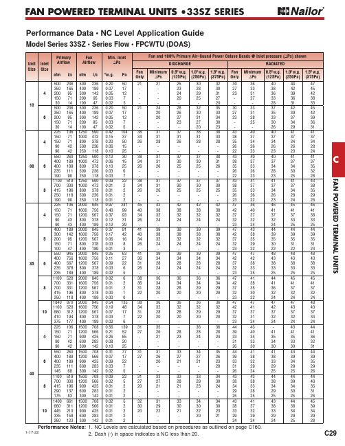
FAN POWERED TERMINAL UNITSFAN POWERED TERMINAL UNITS • CC291-17-22FAN POWERED TERMINAL UNITS •33SZ SERIESPerformance Data • NC Level Application GuideModel Series 33SZ • Series Flow • FPCWTU (DOAS)1. NC Levels are calculated based on procedures as outlined on page C160.2. Dash (-) in space indicates a NC less than 20.Performance Notes:F A N P O W E R E D T E R M I N A L U N I T SFAN POWERED TERMINAL UNITS •C3011-5-21FAN POWERED TERMINAL UNITS • 33SZ SERIESPerformance Data • NC Level Application GuideModel Series 33SZ • Series Flow • FPCWTU (DOAS)For full performance table notes, see page C35.FAN POWERED TERMINAL UNITSFAN POWERED TERMINAL UNITS • CC3111-5-21FAN POWERED TERMINAL UNITS • 33SZ SERIESPerformance Data • Discharge Sound Power LevelsModel Series 33SZ • Series Flow • FPCWTU (DOAS)For full performance table notes, see page C35.F A N P O W E R E D T E R M I N A L U N I T SFAN POWERED TERMINAL UNITS •C3211-5-21FAN POWERED TERMINAL UNITS • 33SZ SERIESPerformance Data • Discharge Sound Power LevelsModel Series 33SZ • Series Flow • FPCWTU (DOAS)For full performance table notes, see page C35.FAN POWERED TERMINAL UNITSFAN POWERED TERMINAL UNITS • CC3311-5-21FAN POWERED TERMINAL UNITS • 33SZ SERIESPerformance Data • Radiated Sound Power LevelsModel Series 33SZ • Series Flow • FPCWTU (DOAS)For full performance table notes, see page C35.F A N P O W E R E D T E R M I N A L U N I T SFAN POWERED TERMINAL UNITS •C3411-5-21FAN POWERED TERMINAL UNITS • 33SZ SERIESFor full performance table notes, see page C35.Performance Data • Radiated Sound Power LevelsModel Series 33SZ • Series Flow • FPCWTU (DOAS)FAN POWERED TERMINAL UNITSFAN POWERED TERMINAL UNITS •C35FAN POWERED TERMINAL UNITS • 33SZ SERIESPerformance Notes for Sound Power Levels:1. Discharge sound power is the noise emitted from the unit discharge into the downstream duct.2. Radiated sound power is the breakout noise transmitted through the unit casing walls.3. Sound power levels are in decibels, dB re 10-12 watts.4. All sound data listed by octave bands is raw data without any corrections for room absorption or duct attenuation. Dash (-) in space indicates sound power level is less than 20 dB or equal to background.5. Minimum inlet ∆Ps is the minimum operating pressure of the primary air valve.6. Asterisk (*) in space indicates that the minimum inlet static pressure requirement is greater than 0.5" w.g. (125 Pa) at rated airflow.7. Data derived from independent tests conducted in accordance with ANSI/ASHRAE Standard 130.Performance NotesModel 33SZ • Series Flow • FPCWTU (DOAS)Explanation of NC Levels:1. NC levels are calculated from the published raw data and based on procedures outlined in AHRI Standard 885, Appendix E.2. Discharge sound attenuation deductions are based on environmental effect, duct lining, branch power division, insulated flex duct, end reflection and space effect and are as follows:3. Radiated sound attenuation deductions are based on a mineral tile ceiling and environmental effect and are as follows:4. Min. inlet ∆Ps is the minimum static pressure required to achieve rated airflow (damper full open).5. Dash (–) in space denotes an NC level of less than 20.6. Discharge (external) static pressure is 0.25" w.g. (63 Pa) in all cases.7. For a detailed explanation of the attenuation factors and the procedures for calculating room NC levels, please refer to the Performance Data Explanation in this section and the Acoustical Engineering Guidelines in the Engineering Section of this catalog.Discharge attenuation Octave Band2 3 4567< 300 cfm 242839535940300 – 700 cfm 272940515339> 700 cfm293041515239Radiated attenuation Octave Band2 3 4567Total dB reduction181920263136。
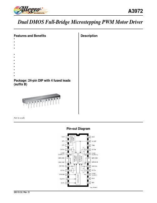
A3972Selection GuidePart Number PackingA3972SB-T15 pieces/tubeAbsolute Maximum RatingsCharacteristic Symbol Notes Rating Units Load Supply Voltage V BB50V Output Current*I OUT±1.5A Logic Supply Voltage V DD7.0V Logic Input Voltage Range V IN–0.3 to V DD + 0.3V Reference Voltage V REF3V Sense Voltage (DC)V S500mV Package Power Dissipation P D 3.1W Operating Ambient Temperature T A Range S–20 to 85ºC Junction Temperature T J150ºC Storage Temperature T stg–55 to 150ºC *Output current rating may be limited by duty cycle, ambient temperature, and heat sinking. Under any set of conditions, do not exceed the specifi ed current rating or a junction temperature of 150°C.FUNCTIONAL BLOCK DIAGRAMELECTRICAL CHARACTERISTICS at T A = +25°C, V BB = 50 V, V DD = 5.0 V, V S = 0.5 V,f PWM < 50 kHz (unless otherwise noted).LimitsMax.Typ.UnitsConditions Min.Characteristic SymbolTestLoad Supply Voltage Range V BB Operating 15 — 50 VDuring sleep mode 0 — 50 VLogic Supply Voltage Range V DD Operating 4.5 5.0 5.5 VLoad Supply Current I BB f PWM < 50 kHz — — 8.0 mAOperating, outputs disabled — — 6.0 mASleep or idle mode — — 20 μALogic Supply Current I DD f PWM < 50 kHz — — 12 mA10—mA—OutputsoffIdle mode (D0 = 1, D18 = 0) — — 1.5 mASleep mode — — 100 μAOutput DriversμAOutput Leakage Current I DSS V OUT = V BB —50<1.0V OUT = 0 V — <-1.0 -50 μAOutput On Resistance r DS(on)Source driver, I OUT = –1.5 A — 0.5 0.55 ΩSink driver, I OUT = 1.5 A — 0.315 0.35 ΩBody Diode Forward Voltage V F Source diode, I F = 1.5 A — — 1.2 VSink diode, I F = 1.5 A — — 1.2 VControl LogicLogic Input Voltage V IN(1) 2.0 — — VV IN(0)— — 0.8 VLogic Input Current I IN(1)V IN = 2.0 V — <1.0 20 μAI IN(0)V IN = 0.8 V — <-2.0 -20 μAOSC Input Frequency Range f OSC Divide by one 2.5 — 6.0 MHz(D0 =1, D13 = 0, D14 = 1)OSC Input Duty Cycle — 40 — 60 %Input Hysterisis ΔV IN0.20 — 0.40 Vcontinued next page ...ELECTRICAL CHARACTERISTICS at T A = +25°C, V BB = 50 V, V DD = 5.0 V, V S = 0.5 V,f PWM < 50 kHz (unless otherwise noted).LimitsMax.Typ.UnitsTestConditions Min.Characteristics SymbolControl Logic (continued)Internal Oscillator f OSC OSC shorted to ground 3.0 4.0 5.0 MHzR OSC = 51 kΩ 3.4 4.0 4.6 MHzDAC Accuracy (total error) E T Relative to DAC reference buffer — ±1/2 — LSBoutput, D0 = 0, D17 = 0Reference Input Voltage Range V REF(EXT) 0.5 — 2.6 V—mV±10 Reference Buffer Offset V OS —Reference Divider Ratio V REF/V S D0 = 0, D18 = 0 — 8.0 — —D0 = 0, D18 = 1 — 4.0 — —Reference Input Current I REF V REF = 2.0 V — — ±0.5 μAInternal Reference Voltage V REF(INT) 1.94 2.0 2.06 VGain (G m) Error (note 3) E G D0 = 0, D17 = 0,D18 = 0, DAC = 63 — 0 ±6 %D18 = 0, DAC = 31 — 0 ±9 %D18 = 1, DAC = 63 — 0 ±6 %D18 = 1, DAC = 15 — 0 ±10 %Comparator Input Offset Voltage V IO V REF = 0 V — ±5.0 — mVPropagation Delay Times t pd50% to 90%:PWM change to source on 500 800 1200 nsPWM change to source off 50 150 350 nsPWM change to sink on 500 800 1200 nsPWM change to sink off 50 150 350 nsCrossover Dead Time t dt300 700 900 nsThermal Shutdown Temperature T J— 165 — °CThermal Shutdown Hysteresis ΔT J— 15 — °C4.2V4.45UVLO Enable Threshold V UVLO IncreasingV DD 3.9UVLO Hysteresis ΔV UVLO0.05 0.10 — VNOTES: 1. Typical Data is for design information only.2. Negative current is defi ned as coming out of (sourcing) the specifi ed device terminal.3. E G = [(V REF/Range) – V S]/(V REF/Range).Serial Interface. The A3972SB is controlled via a 3-wire (clock, data, strobe) serial port. The programmable functions allow maximum fl exibility in con fi guring the PWM to the motor drive requirements. The serial data is written as two19-bit words: 1 bit to select the word and 18 bits of data. The serial data is clocked in starting with D18.Word 0 Bit AssignmentsBit Function D0 Word select = 0 D1 Bridge 1, DAC, LSB D2 Bridge 1, DAC, bit 2 D3 Bridge 1, DAC, bit 3 D4 Bridge 1, DAC, bit 4 D5 Bridge 1, DAC, bit 5 D6 Bridge 1, DAC, MSB D7 Bridge 2, DAC, LSB D8 Bridge 2, DAC, bit 2 D9 Bridge 2, DAC, bit 3 D10 Bridge 2, DAC, bit 4 D11 Bridge 2, DAC, bit 5 D12 Bridge 2, DAC, MSB D13 Bridge 1 phase D14 Bridge 2 phase D15 Bridge 1 mode D16 Bridge 2 mode D17 REF select D18 Range selectD1 – D6 Bridge 1 Linear DAC. Six-bit word sets desired current level for Bridge 1. Setting all six bits to zero disables Bridge 1, with all drivers off (See current regulation section of functional description).D7 – D12 Bridge 2 Linear DAC. Six-bit word sets desired current level for Bridge 2. Setting all six bits to zero disables Bridge 2, with all drivers off (See current regulation section of functional description).FUNCTIONAL DESCRIPTIONcontinued next page ...D13 Bridge 1 Phase. This bit controls the direction of output current for Load 1.D13 OUT 1A OUT 1B0 L H 1 H LD14 Bridge 2 Phase. This bit controls the direction of output current for Load 2.D14 OUT 2A OUT 2B 0 L H1 H L D15 Bridge 1 Mode.D15 Mode 0 Mixed-decay 1 Slow-decay D16 Bridge 2 Mode.D16 Mode 0 Mixed-decay 1 Slow-decayD17 REF Select. This bit determines the reference input for the 6-bit linear DACs. D17 Reference Voltage 0 Internal 2 V1External (3 V max)D18 G m Range Select. This bit determines the scaling factor (4 or 8) used.D18 Divider Load Current 0 1/8 I TRIP = V DAC /8R S 1 1/4 I TRIP = V DAC /4R SFor example, with a master oscillator frequency of 4 MHz, the fi xed off-time will be adjustable from 1.75 μs to 63.75 μs in increments of 2 μs.D8 – D11 Fast Decay Time. These four bits set the fast-decay portion of fi xed off-time for the internal PWM control circuitry. The fast-decay portion is de fi ned by:t fd = [(1 + N) x 8/f OSC ] - 1/f OSC where N = 0 (15)For example, with an oscillator frequency of 4 MHz, the fast-decay time will be adjustable from 1.75 μs to 31.75 μs in incre-ments of 2 μs. For t fd > t off , the device will effectively operate in fast-decay mode.D12 – D13 Oscillator Control. A 4 MHz internal oscillator is used for the timing functions and charge-pump clock. If more precise control is required, an external oscillator can be input to the OSC terminal. To accommodate a wider range of system clocks, an internal divider is provided to generate the desired MO frequency according to the following table: D13 D12 OSC 0 0 4 MHz internal clock 0 1 External clock 1 0 External clock/2 1 1 External clock/4D14 – D15 Synchronous Recti fi cation.D15 D14 Synchronous Recti fi er 0 0 Active 0 1 Disabled 1 0 Passive 1 1 Low side only The different modes of operation are in the synchronous recti fi -cation section of the functional description.D16, D17. These bits are reserved for testing and should be programmed to zero during normal operation.D18 Idle Mode. The device can be placed in a low power “idle” mode by writing a “0” to D18. The outputs will be dis-abled, the charge pump will be turned off, and the device will draw a lower load supply currrent. The undervoltage monitor circuit will remain active. D18 should be programmed high for 1 ms before attempting to enable any output driver.Word 1 Bit AssignmentsBit Function D0 Word select = 1D1 Blank-time LSBD2 Blank-time MSB D3 Off-time LSB D4 Off-time bit 1 D5 Off-time bit 2 D6 Off-time bit 3D7 Off-time MSB D8 Fast-decay time LSB D9 Fast-decay time bit 1 D10 Fast-decay time bit 2 D11 Fast-decay time MSB D12 C0 oscillator control D13 C1 oscillator control D14 SR control bit 1 D15 SR control bit 2 D16 Reserved for testing D17 Reserved for testing D18 Idle modeD1 – D2 Blank Time. These two bits set the blank time for the current-sense comparator. When a source driver turns on, a current spike occurs due to the reverse-recovery currents of the clamp diodes and/or switching transients related to distributed capacitance in the load. To prevent this current spike from er-roneously resetting the source-enable latch, the sense comparator is blanked. The blank timer runs after the off-time counter to provide the programmable blanking function. The blank timer is reset when PHASE is changed. D2 D1 Time 0 0 4/f OSC 0 1 6/f OSC 1 0 8/f OSC 1 1 12/f OSCD3 – D7 Fixed Off Time. These fi ve bits set the fi xed off-time for the internal PWM control circuitry. Fixed off-time is de fi ned by:t off = [(1 + N) x 8/f OSC ] - 1/f OSCwhere N = 0 (31)FUNCTIONAL DESCRIPTION (continued)continued next page ...V REG. This internally generated supply voltage is used to run the sink-side DMOS outputs. V REG is internally monitored and in the case of a fault condition, the outputs of the device are disabled. The V REG pin should be decoupled with a 0.22 μF capacitor to ground.Current Regulation. The reference voltage can be set by ana-log input to the REF terminal, or via the internal 2 V precision reference. The choice of reference voltage and sense resistor set the maximum trip current.I TRIPMAX = V REF/(Range x R S) Microstepping current levels are set according to the following equations:I TRIP = V DAC/(Range x R S)V DAC = [(1 + DAC) x V REF]/64where DAC input code equals 1 to 63 and Range is 4 or 8 as selected by Word 0, D18. Programming the DAC input code to zero disables the bridge, and results in minimum load current. PWM Timer Function. The PWM timer is programmable via the serial port to provide fi xed off-time PWM signals to the con-trol block. In mixed-decay mode, the fi rst portion of the off time operates in fast decay, until the fast-decay time count is reached, followed by slow decay for the rest of the fi xed off-time period. If the fast-decay time is set longer than the off-time, the device effectively operates in fast-decay mode.Oscillator. The PWM timer is based on an oscillator input, typically 4 MHz. The A3972SB can be confi gured to select ei-ther a 4 MHz internal oscillator or, if more precision is required, an external clock can be connected to the OSC terminal. If an external clock is used, three internal divider choices are select-able via the serial port to allow fl exibility in choosing f OSC, based on available system clocks. If the internal oscillator op-tion is used, the absolute accuracy is dependent on the process variation of resistance and capacitance. A precision resistor can be connected from the OSC terminal to V DD to further improve the tolerance. The frequency will be:f OSC = 204 x 109/R OSCIf the internal oscillator is used without the external resistor, the OSC terminal should be connected to ground.Sleep Mode. The input terminal SLEEP is dedicated to putting the device into a minimum current draw mode. When pulled low, the serial port will be reset to all zeros and all circuits will be disabled.Shutdown. In the event of a fault due to excessive junction temperature, or low voltage on V CP or V REG, the outputs of the device are disabled until the fault condition is removed. At power up, or in the event of low V DD, the UVLO circuit disables the drivers and resets the data in the serial port to zeros. Synchronous Rectifi cation. When a PWM off-cycle is triggered, either by a bridge disable command or internal fi xed off-time cycle, the load current will recirculate according tothe decay mode selected by the control logic. The A3972SB synchronous rectifi cation feature will turn on the appropriate MOSFET(s) during the current decay and effectively short out the body diodes with the low r DS(on) driver. This will lower power dissipation signifi cantly and can eliminate the need for external Schottky diodes for most applications.Four distinct modes of operation can be confi gured with the two serial port control bits:1. Active Mode. Prevents reversal of load current by turningoff synchronous rectifi cation when a zero current level isdetected.2. Passive Mode. Allows reversal of current but will turnoff the synchronous rectifi er circuit if the load current inver-sion ramps up to the current limit.3. Disabled. MOSFET switching will not occur during loadrecirculation. This setting would only be used with fourexternal clamp diodes per bridge.4. Low Side Only. The low-side MOSFETs will switch onduring the off time to short out the current path throughthe MOSFET body diode. With this setting, the high-sideMOSFETs will not synchronously rectify so four externaldiodes from output to supply are recommended. This mode is intended for use with high-power applications where itis desired to save the expense of two external diodes perbridge. In this mode, the sink-side MOSFETs are chopped during the PWM off time. In all other cases, the source-side MOSFETs are chopped in response to a PWM off com-mand.continued next page ...FUNCTIONAL DESCRIPTION (continued)Current Sensing.To minimize inaccuracies in sensing the IPEAKcurrent level caused by ground-trace IR drops, the senseresistor should have an independent ground return to the ground terminal of the device. For low-value sense resistors, the IR drops in the sense resistor’s PCB traces can be signi fi cant and should be taken into account. The use of sockets should beavoided as they can introduce variation in R S due to their contact resistance.Thermal Protection. Circuitry turns off all drivers when the junction temperature reaches 165°C typically. It is intended only to protect the device from failures due to excessive junction temperature and should not imply that output short circuits are permitted. Thermal shutdown has a hysteresis of approximately 15°C.Serial Port Write Timing Operation. Data is clocked into a shift register on the rising edge of CLOCK signal. Normally, STROBE will be held high, and only will be brought low to initiate a write cycle. The data is written MSB fi rst, followed by the word-select bit. Refer to serial port diagram for timing requirements.APPLICATIONS INFORMATIONA. Minimum Data Setup Time .......................................15 nsB. Minimum Data Hold Time ........................................10 nsC. Minimum Setup Strobe to Clock Rising Edge ........150 nsD. Minimum Clock High Pulse Width ...........................40 nsE. Minimum Clock Low Pulse Width ............................40 nsF. Minimum Setup Clock Rising Edge to Strobe ...........50 ns G . Minimum Strobe Pulse Width .................................150 ns H. Minimum Setup Sleep to Strobe Falling ...................50 μsLayout. The printed wiring board should use a heavy ground plane. For optimum electrical and thermal performance, the driver should be soldered directly onto the board. The ground side of R S should have an individual path to the ground pin(s) of the driver. This path should be as short as physically possible and should not have any other components connected to it. The load supply pin, V BB , should be decoupled with an electrolytic capacitor (>47 μF is recommended) placed as close to the driveras is possible.Dwg. WP-038-1B Package, 24-Pin DIPCopyright ©2000-2007, Allegro MicroSystems, Inc.The products described here are manufactured under one or more U.S. patents or U.S. patents pending.Allegro MicroSystems, Inc. reserves the right to make, from time to time, such de p ar t ures from the detail spec i f i c a t ions as may be required to per-mit improvements in the per f or m ance, reliability, or manufacturability of its products. Before placing an order, the user is cautioned to verify that the information being relied upon is current.Allegro’s products are not to be used in life support devices or systems, if a failure of an Allegro product can reasonably be expected to cause the failure of that life support device or system, or to affect the safety or effectiveness of that device or system.The in f or m a t ion in c lud e d herein is believed to be ac c u r ate and reliable. How e v e r, Allegro MicroSystems, Inc. assumes no re s pon s i b il i t y for its use; nor for any in f ringe m ent of patents or other rights of third parties which may result from its use.For the latest version of this document, visit our website:。
西威变频器调试资料一. 变频器线路说明1。
同步变频器选型方法2。
与常见微机板匹配注意事项(蓝光、新时达、中秀、奔克、里霸)3。
与常用曳引机匹配注意事项(蓝光、欣达、孚信、阿尔法、蒙特纳利、威特)4。
端子与接线说明二。
外部部件说明与选配1。
制动电阻选型2. 滤波器选型3. 编码器与分频卡海德汉hipeface内密控4. 旋转变压器与RES卡三。
操作说明1。
面板操作说明2。
参数修改步骤3。
参数保存方法四。
参数设置表及简要说明五. 变频器自学习调试1。
电流自学习2. 无齿定位自学习六。
速度曲线与时序的说明七. 舒适感调试说明1。
PI调节2。
预转矩调试八。
常见显示错误与处理方法1. 报警清除方法2。
软件报错的说明3。
硬件故障处理方法九。
3.5与3.4新增、改变内容对照表十。
附录1 3.5版本说明十一。
反馈表一。
变频器线路说明1。
同步变频器选型方法当永磁同步无齿曳引机选配变频器型号时,除了要符合曳引机的铭牌参数外,一般还需要满足1.6 Ib>2。
0Ij,的电流公式。
Ib:变频器的额定电流。
Ij:曳引机的额定电流。
2. 与常见微机板匹配注意事项(蓝光、新时达、中秀、奔克、里霸)(未完善)因西威变频器软件系统比较强大,启动时比一般变频器要慢.在电梯系统上电后,变频器正常信号给的比较慢,新时达微机板等会不断的断合变频器电源,从而无法正常运行运行。
具体处理方法:将变频4060号参数置1(反),微机板中Drive OK输入端设为常闭有效。
3。
与常用曳引机匹配注意事项(蓝光、欣达、孚信、阿尔法、蒙特纳利、威特)(未完善) 进口曳引机参数不详,,具体参数要向曳引机销售方咨询。
4. 端子与接线说明(详细参见说明书P50)a、主线路注意事项制动电阻应接在BR1和C之间,不能接在C和D或者D和BR1之间,如果接错会损坏变频器"主线路端子在接线时要拧紧,不然会影响变频器和电机性能,容易产生故障"b、控制线路注意事项采用变频器内部24V时,需要将变频器18、19端子接入回路。
怎样查出创维彩电机芯的型号创维电视机是以机芯来区分机型、图纸、数据、遥控器等关键信息,鉴于很多会员在修理创维电视机时很难找到、甚至找不到机芯型号的位置,在此告知大家几个可以准确找到机芯型号的常见点:1、原机遥控器,原机配带的遥控器的背面一般会有一张小贴纸,上面的型号即为本机机芯号。
2、原机说明书,上门服务时可以向用户索要说明书,不用打开,在说明书背页的串号上即可发现准确的机芯型号,如:创维34TPDP为5D20等机芯,而网络搜索到的信息只显示该机为5D78机芯。
3、机壳背面的贴纸,在机壳的背面音视频接口处通常会有一张小贴纸,上面一般记录着机芯、机号、生产日期等信息,很容易找到。
4、主板,一部分没有遥控器、说明书以及机壳贴纸的机器就无法找到机芯型号了吗?不是的,很多机型在主板的明显空位会留下串号,上面也清楚的记录了本机的机芯号码,仔细查找不难发现。
若经以上查找均未发现机芯号码的踪迹(这样的机器也不是没有),那么就需要借助主板上的主要集成电路和本机型号来查找了。
部分创维彩电机芯对照表大全6D76机芯机型:34T66HD;CPU:M37274/M37281;解码:DPTV6D78机芯CPU:M372816D92机芯解码:LA76930;2004-05-26版本,行频:33.75K6D92机芯29英寸北京松下管;解码:LA76930;2004-05-26版本,行频:35K6D92机芯25英寸;解码:LA76930;2004-08-02版本;6路AV,行频:35K6D92机芯25英寸;解码:LA76930;2004-08-02版本;4路AV,行频:35K6D95机芯29英寸;解码:DVP004;CPU:S88496D95机芯34英寸;解码:DVP004;CPU:S88496D96机芯29英寸;解码:SVPV12;CPU:S8849创维I系列机芯所用集成电路查询机芯集成电路型号5I01机芯双频机;CPU:CCZ3005;解码:VPC32155I30机芯解码与CPU为:VCT3803创维M系列机芯所用集成电路查询机芯集成电路型号5M10机芯双频机;CPU:M37274;解码:VPC3210A6M20机芯29寸高清彩电系列;CPU:DS88C(P)4504;解码:DPTV-3D6M20机芯34寸高清彩电系列;CPU:DS88C(P)4504;解码:DPTV-3D6M23机芯34寸高清彩电系列:配松下管6M23机芯34寸高清彩电系列:配东芝管6M23机芯34寸高清彩电系列:配三星管创维P系列彩电机芯所用集成电路型号查询机芯集成电路型号3P10/4P10机芯解码:OM8838;CPU:MTV8803P20/4P20机芯解码:OM8838;CPU:KS88C83163P21机芯解码:OM8838PS;CPU:4749-Z00010-42\4749-Z00011-423P30机芯CPU与解码为:TDA9370PS-N23P30机芯CPU与解码为:TDA9370PS|N2|AI08433P30机芯CPU与解码为:TDA9370PS|N23P30机芯CPU与解码为:OM8370PS4P30机芯CPU与解码为:TDA9370PS-N2;四路AV输入4P30机芯CPU与解码为:TDA9370PS;二路AV输入4P30机芯CPU与解码为:TDA9370PS;一路AV输入4P36机芯29寸华飞管;CPU与解码为:TDA9370;一路AV输入5P03机芯CPU:47-Z00001-42到47-Z00007-42都为此机芯CPU,其中Z0003与Z0006为带丽音功能,可互换,另外其它的可互换。