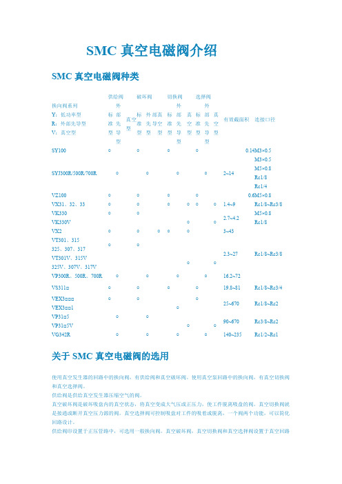
SMC电磁阀VT307Y-5GS-02外形尺寸
- 格式:doc
- 大小:474.61 KB
- 文档页数:2
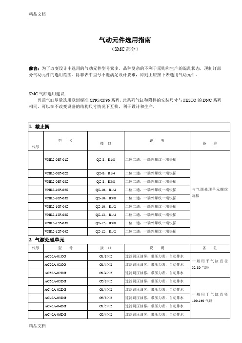

EVT307-5DZ-01F-QLarge Flow Capacity, yet Compact Size. Dimensions (W X H X D)······30 X 54.5 X 33 VT307······N l/min 206.02 or more, 1/4 Low Power ConsumptionVT/VO307······4.8W DC/Standard StyleVT/VO307YVT/VO307W)······2W DC/Energy Saving Style Suitable for Use in Vacuum Applications –101.2kPa(Vacuum Style: VT/VO307V, VT/VO307W)1 Valve, 6 Functions. (Universal Porting)Selective porting can provide 6 valve func-tions, such as N.C. valve, N.O. valve, Divider valve, Selector valve etc.JIS Symbol 3 Port Direct Operated Poppet Rubber Seal Series VT3072.5-12.5-2Option SpecificationsHow to OrderExclusive use of VT307E is recommended for continuous duty with long time loading.VT307Caution1. This model is for continuous duty, not for high cycle rates. But even in low cycle rate, if energiz-ing valve more than once a day, consult SMC.2. Energizing solenoid shouldbe done at least once in 30 days.If low power consumption is required for electronic control, “VY307Y”(2WDC) is recommended.Specifications different from standard are as fol-This vacuum model has less air leakage than the standard model under low pres-sure.CautionSince this valve has slight air leakage, it can not be used for vacuum holding (including positive pressure holding) in the pressure container.Specifications different from standard are as follows.Operating pressure range–101.2kPa to 0.1MPa2.5-3Be sure to read before handling.Refer to p.0-33 to 0-36 for Safety Instruction and common precautions.1. Make sure that dust and/or other foreign materials should not enter the valve from the unused port such as exhaust port. Also, since there is a bleed port for the armature in the manual override part, do not allow accumulation of dust and/or other foreign materials to block bleed port.How to Calculate Flow RateRefer to p.0-36 for the calculation of flow rate.De-energizedEnergizedOperation principles <De-energized>Spool valve w is pushed upward by the return spring e , port [P] is closed, and then port [A] and port [R] are opened.Air flow direction:Port [P] Block, [A] [R]<Energized>When an electric current is applied to the molded coil r , the armature t is attracted to the pole y , and through the push rod u , it pushes down the spool valve w . Then port [P] and port [A] are con-nected. At this time, there will be gaps between the armature t and the pole y , but the armature will be magnetically attracted to the pole y . Air flow direction:VT307DIN connector (with indicator light and surge voltage suppressor) are connected inside as in the figure below. Connect to the cor-responding power supply.terminal blockblock • Applicable cable O.D. Type T: ø4.5 to ø7mm Type E: ø2.3 to ø2.8mm Type D: ø4.5 to ø7mm • Applicable crimp terminal T ype E/T: 1.25-3, 1.25-3S 1.25Y -3N, 1.25Y -3SRound or “Y” shaped crimped terminals Voltage 100V AC 200V AC DC OthersColour Blue RedRed (+), Black (–)GrayTerminal No.DIN Terminal Terminal1++ CautionoverrideVT3072.5-42.5-5VV307VT307 manifoldE Series VT307ManifoldCautionq Each valve is fixed to the manifold base with two M4 mounting screws. Tighten the screws evenly when re-mounting. w For mounting, tighten M4 or equivalent screws evenly into the mounting holes of the manifold base.Tightening torque of the mounting screw (M4): 1.4NmBe sure to read before handling.Refer to p.0-33 to 0-36 for Safety Instruction and common precautions.VT307 manifold is B mount style and available both as a common exhaust and individual exhaust model.Manifolded valve can be easily con-verted from N.C. normally closed to N.O. normally open merely by turn-ing over the switch cover.q For the common exhaust style, pressur-iza- tion or evacuation of the R-port can cause malfunction.VV307-01-052-FVV307-01-063- -FHow to Order Manifold BaseFigure: N.C.Note 1) "DXT060-51-13B" and "DXT152-14-1B" are for long time loading.Note 2) For mounting single solenoid valve for manifolds.Function PipingMounting2.5-6VT307VV307-01- 2-01-Fn: Station L: Dimensions (mm)VT307 L:Dimensions (mm)n: Station2.5-7Large Flow Capacity, yet Compact Size. Dimensions(W X H X D)······45 X 89.5 X 45 VT317······N l/min 687.05 1/4Suitable for Use in Vacuum Applications -101.2kPa(Vacuum Model: VT/VO317V)1 Valve, 6 Functions. (Universal Porting)Selective porting can provide 6 valve func-tions, such as N.C. valve, N.O. valve, Divider valve, Selector valve etc.JIS Symbol 3 Port Direct Operated Poppet Rubber Seal Series VT3172.5-82.5-9Option SpecificationsHow to orderExclusive use of VT317E is recommendedfor continuous duty with long time loading.VT3171. This model is for continuous duty, not for high cycle rates. But even in low cycle rates, if energizing the valve more than once a day, consult SMC.2. Energizing solenoid should be done at least once in 30 days.This vacuum model has less air leakage than the standard model under low pressure. It is recommended for vacuum applications.1. Since this valve has slight air leakage, it can not be used for vacuum holding (including positive pressure holding) in the pressure container.Specifications different from standard are as follows.Be sure to read before handling.Refer to p.0-33 to 0-36 for Safety Instruction and common precautions.Caution1. A bleed port for the main valve is located at the bottom of the solenoid valve. Since blocking it causes malfunction, do not block it.∗ When mounted on the metallic surface, bleed-ing is normally done from the bleed port through the bleed groove, but when mounted on an elastic surface, elastic shape deformation may close the port.2. Make sure that dust and/or other foreign materi-als should not enter the valve from the unused port such as exhaust port. Also, since there is a bleed port for the armature in the manual over-ride, do not allow accumulation of dust and/or other foreign materials to block bleed port.Protective class class I (Mark: )Operating pressure range –101.2kPa to 0.1MPaHow to Calculate Flow RateRefer to p.0-36 for the calculation of flow rate.CautionCaution2.5-10VT317Operation principles<De-energized>Spool valve w is pushed upward by the returnspring e, port [P] is closed, and port [A] and port[R] are opened.<Energized>When an electric current is applied to the moldedcoil r, the armature t is attracted to the pole yand through the push rod u, it pushes down thespool valve w. Then port [P] and port [A] are con-nected. At this time, there will be gaps betweenthe armature t and the pole y, but the armature1) Series VT317 can change electrical entryangle. (4 positions)2) How to change:Loosen the nut q, remove the coil w fromthe body assembly e, place the positioningpin r at the required place, put back the coilw to its place, and tighten sufficiently withlock nut q.• With indicator light and surge suppressor (Z)2) DCDIN connector/Conduit terminal• With surge voltage suppressor (S)48V DC or less100V DCDIN connector is connected inside as in thefigure below. Connect to the correspondingpower supply.Applicable cable O.D.ø6 to ø12Note)For those with an external measur–ement of ø9 to ø12, remove the innerportion of the ground gasket beforeusing.Applicable crimping terminalThe maximum size for the roundtermi–nal is 1.25mm -3.5 and for the Y termi–nal is 1.25mm -4.22VT317Dimensions (mm)DDIN connector: VT317-2.5-112.5-12Series VT317ManifoldBe sure to read before handling.Refer to p.0-33 to 0-36 for Safety Instruction and common precautions.VT307 manifold is B mount style and available both as a common exhaustand individual exhaust model.VV317-02-051-02-ACommon exhaustVV317-02-051-02Individual exhaustVV317-02-053-02mounting adaptor.Note 3) Can also be applied to Series VVT320 manifold.∗) Changing from NC to NO This product is delivered as N.C. valve.If N.O. valve is needed, remove mounting screws of the required valve and turn the valve at 180 degrees. (Make sure that thereare O rings fixed on 4 positions of the valve surface.) Then, tighten the mounting screws to fix the valve to the manifold base.Part No.PVT317-53-1A DXT010-37-4q (M4): 1.4Nmw the manifold base.2.5-13VT317With mounting adaptor/VV317-02-Valve port location2121106316715242131985259244630529073513368397382L: Dimensions (mm)VT317Without mounting adaptor/VV317-02- 3-02 2.5-142.5-15Compact yet provides a large valve capacityDimensions (W X H X D) ···55 X 118 X 53VT325: N l /min 1472.25···3/8A single valve with 6 valve functions(Universal porting style)Six valve functions can be attained by selecting the piping ports. (Enabling the NC valve, NO valve, divider valve, selector valve, etc. to be used as desired.)Can be used for vacuum applications–101.2kPa(Vacuum style: VT/VO325V)3 Port Poppet Rubber SealSeriesVT325VT325-DSymbol1.The bottom of the solenoid valve has a breatherhole for the main valve. Take proper measures toprevent this hole from being blocked as this willlead to a malfunction.∗ Ordinarily, when the solenoid valve is mountedon a metal surface, it can breathe through thebreather hole, via the breather groove, However,in particular, if the surface to be mounted ismade of rubber, the rubber could deform andblock the hole.2.5-16ConstructionOption SpecificationsB e sure to read before handling.Refer to p.0-33 to 0-36 for SafetyInstructions and common precautions.CautionFlow rateRefer to p.0-36 for flow rate calculation.D e-e n e r-gizedEnergizedOperation principles<De-energized>The spool e is pushed upward by theforce of the spring r and the air passagebetween port x and port c is openedand port z is blocked.Air flow direction: z Block, x c<Energized>When the coil y is energized the plungeru ispulled down depressing the spoole via the overtravel assembly i and theair passage between port z and port xis opened and port c is blocked.Air flow direction: z x, c Block1. How to wire1) Loosen the fix screw and pull off the connector fromthe pin plug.2) Make sure to pull out the retaining screw beforeinserting a screwdriver into the groove at the lowerportion of the terminal board. Then, push the screw-driver up to separate the terminal board and theterminal cover.3) Following the wiring procedure, properly connect thewires to the specified terminals.4) As a rule, wires are connected to the terminals usingcrimp-style terminals. Therefore, select crimp-styleterminals that do not overstrain the terminal hard-ware.Wiring figureSingle solenoid 1VT3251.For vacuumIn contrast to the standard product, this vacuumspecification valve has less air leakage at low pres-sures, a feature that should be taken into considera-tion when using this valve for vacuum applications.Caution2.Manual override with lock1) Using a screwdriver, pushthe manual override button thatis located in the head portion of the solenoid valve in orderto directry push the spool valve downward, thus causing thevalve to switch.2) With the button remaining pushed down, turn it approximately90° clockwise or counterclockwise to maintain the manual over-ride locked state.3) To revert to the original state, keep the button pushed downand turn it approximately 90° clockwise or counterclockwise.2. Change of electrical entryOnce the terminal cover is separated fromthe terminal block, it can be rotated in anydirection (4 directions, each 90°) to changethe orientation of the electrical entry.2. Take proper measures to prevent dust or foreign mat-ter from entering through unused ports.The grommet portion contains a breather hole for thecore. Take proper measures to prevent dust or foreignmatter from accumulating in this area.Pressure range–101.2kPa to 0.1MPaPin plug1)Because this valve leaks air, it cannot beused for maintaining a vacuum (or pres-sure) in a pressure vessel.3. CautionTo insert the connector into the pin plug orto pull it out, do so as vertically as possible,without tilting.4. Applicable cableCord external: ø6 to ø12Note: For those with external measurements of ø9 to ø12, remove the innerportion of the ground gasket beforeuse.5. Applicable crimp-style terminalsThe maximun size for the round terminalis 1.25mm-3.5 and for the Y terminal is1.25mm-4.22VT325 Dimensions (mm)DIN terminal (D)With locking manual override2.5-17Series VT325ManifoldCommon exhaustVT325 Series Manifold Model has a B-mount style with common exhaust.DimensionsProtective class class I (Mark: )2.5-1812Common Exhaust2.5-19EVT307-5DZ-01F-Q。

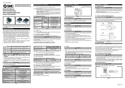



文件No.SY3000∗-OMH0002电磁阀SY系列(搭载V100先导阀)安全上的注意事项 --------------------------------------------------------------------------------------2,3设计上的注意事项 -------------------------------------------------------------------------------------- 4,5 选定 ---------------------------------------------------------------------------------------------------------4,5安装 -------------------------------------------------------------------------------------------------------- 6配管 -------------------------------------------------------------------------------------------------------- 6配线 -------------------------------------------------------------------------------------------------------- 6润滑 -------------------------------------------------------------------------------------------------------- 6气源 --------------------------------------------------------------------------------------------------------7使用环境-----------------------------------------------------------------------------------------------7维护点检-----------------------------------------------------------------------------------------------7产品个别注意事项 ---------------------------------------------------------------------------------------- 8~14 故障及应对方法 -------------------------------------------------------------------------------------------15,16URL ㊟对本使用说明书进行的变动不另行通知,请谅解。

