06 UPS屏 JZH-9-6
- 格式:doc
- 大小:64.50 KB
- 文档页数:2


PRODUCT SPECIFICATIONLithium Ion Battery System for UPS – U6A4 (34.6kWh, 32.6kWh, 28.5kWh, 26.5kWh, 24.4kWh, 20.4kWh)Internal ApprovalCustomer ApprovalI hereby approve the following product of Samsung SDI Co., Ltd. for production. Product: Li-ion Battery System for UPSSignatureDateRevision HistoryTable of ContentsInternal Approval (2)Customer Approval (2)Revision History (3)Table of Contents (4)Tables (5)Figures (6)Acronyms and Abbreviations (7)1. Product Overview (8)1.1 Scope (8)2. Product Description (9)3. Safety Information and Handling (10)3.1 Safety Symbols (10)3.2 General Safety Information (11)3.2.1 Protective Equipment (11)3.2.2 Organic Solvent Electrolyte (11)3.2.3 Electrolyte Vent Product (11)3.2.4 High Voltage Sources (12)3.2.5 Unloading and Unpacking (12)3.2.6 Storage (12)3.3 General Handling Information (13)4. Specification and Characteristics (14)5. Block Diagram and Configuration (19)6. Detail Product Description (20)6.1 Battery Module (20)6.2 BCU (21)6.3 SMPS Assembly (22)6.4 Rack Frame (24)7. LED Indication (25)7.1 Battery Status Display (25)8. Evaluation (26)9. Packaging and Shipment (27)10. Service, Maintenance and Warranty (28)10.1 Service (28)10.2 Maintenance (28)10.3 Warranty (28)Contact Information (29)Table 1: Acronyms and Abbreviations (7)Table 2: Component Information (8)Table 3: Safety Symbols (10)Table 4: Battery System General Specification (14)Table 5: 136S Battery System Specification (15)Table 6: 128S Battery System Specification (15)Table 7: 112S Battery System General Specification (16)Table 8: 104S Battery System General Specification (16)Table 9: 96S Battery System General Specification (17)Table 10: 80S Battery System General Specification (17)Table 11: Configurations (18)Table 12: Cable and lug terminal requirements (21)Table 13: AC Terminal and Cable Description (3 phase) (23)Table 14: AC Terminal and Cable Description (1 phase) (23)Table 15: LED Indicator (25)Table 16: Indicated Codes (25)Table 17: List of Standards and Regulations (26)Figure 1: 34.6kWh Lithium Ion Energy Storage System (9)Figure 2: Storage Guide (13)Figure 3: General System Block Diagram (19)Figure 4 : Battery Module Type A (20)Figure 5 : Battery Module Type B (20)Figure 6: BCU (21)Figure 7: SMPS Assembly (22)Figure 8: Rack Frame (24)Acronyms and AbbreviationsThe following acronyms and abbreviations are used in this manual.Customer:Model Number:PHR3462-001A (136S), PHR3262-001A (128S), PHR2852-001A (112S), PHR2652-001A (104S),PHR2442-001A (96S), PHR2042-001A (80S)Product Name: Lithium Ion Battery System for UPSSupplier: Samsung SDI Co., Ltd.1.1 ScopeThis document details the safety and handling information, characteristics, requirements, installation instructions, operating guidelines, service, maintenance and warranty of Lithium Ion Battery System manufactured by Samsung SDI Co., Ltd. It is intended to provide certified personnel and users with information on safe handling, installation and usage of the specified product. Consult with Samsung SDI if some usages not described are expected.This product is comprised of the following components.The Battery system consists of four major components: 67Ah 8S1P Battery Module (“Battery Module” hereinafter), Battery Control Unit (BCU) and SMPS Assembly. A single rack configuration of 34.6kWh Battery System is comprised of one BCU and one SMPS Assembly and 17 Battery Modules.Battery Module is the most basic component of the Battery System and it contains the energy storing battery cells. There is a Module BMS inside each Battery Module. Module BMS checks the status of a Battery Module by measuring its voltage and temperature. It also communicates with the BCU to send all measured voltage and temperature data, and to receive commands to control cell balancing.BCU collects all information about the battery system and controls the battery system by switching the main power line and controls each Battery Module by cell balancing. BCU calculates the state-of-charge (SOC) and state-of-health (SOH) of the battery system. Key components in the BCU are Rack BMS, MCCB, and shunt resistor. Rack BMS is the main controller that takes all data from the Module BMS, measures the string voltage and current, determines the state of the battery and controls the MCCB accordingly.SMPS Assembly Type A is comprised of System BMS and switching mode power supply (SMPS). SMPS Assembly Type A supplies power to the BMS and communicates with Uninterruptible Power Supply (UPS). SMPS Assembly Type B is comprised of only SMPS which supplies power to the BMS.Figure 1: 34.6kWh Lithium Ion Energy Storage System3. Safety Information and HandlingThis Part details the safety information that personnel must fully understand and follow while transporting, storing, installing, operating or servicing the Battery System. Before proceeding with unloading, unpacking, handling, installation and operation, read the following details.3.1 Safety Symbols3.2 General Safety InformationThe Battery System provides a safe source of electrical energy when operated as intended and as designed. Potentially hazardous circumstances such as excessive heat or electrolyte mist may occur under improper operating conditions, damage, misuse and/or abuse. The following safety precautions and the warning messages described in this Part must be observed.If any of the following precautions are not fully understood, or if you have any questions, contact Customer Support for guidance. The Safety Part may not include all regulations for your locale; personnel working with the Battery System must review applicable federal, state and local regulations as well as the industry standards regarding this product.3.2.1 Protective EquipmentWhen working with the Battery System, the following personal protective equipment must be worn:-High voltage rated rubber gloves-Safety goggles or other eye protection3.2.2 Organic Solvent ElectrolyteCell components of the Battery System contain organic solvent-based electrolyte. Breach of individual cells may allow some electrolyte to be released from the cell. Direct contact with the liquid electrolyte can cause skin irritation.If contact with the liquid electrolyte occurs, follow the suggestions below to minimize the chance of injury: -Flush eyes immediately with cold running water for at least 15 minutes.-Rinse skin immediately with water for at least 15 minutes.-Remove clothing if soiled.-Seek immediate medical attention.3.2.3 Electrolyte Vent ProductThe Lithium-Ion chemistry used in the Battery System contains an organic solvent-based electrolyte. If the Battery System is misused, damaged or abused, internal cell pressure may increase to excessive levels. Eachcell within the Battery System is equipped with a non-resettable vent so that if internal cell pressure increases, the cell’s vent will activate releasing the electrolyte vent products. When operated as intended and designed, internal cell pressure remains stable and no electrolyte product venting occurs. Other structure (rack, enclosure e.g.) must not interfere gas vent.Organic solvent electrolyte vent products are flammable. To avoid serious injury from the release and ignition of flammable products, the following guidelines must be observed:-Operate the Battery System under conditions only as specified in this manual.-Keep sparks, flames and smoking materials away from the Battery System.-Do not incinerate, puncture or impact the Battery System.-Do not solder or weld to the Battery System.3.2.4 High Voltage SourcesDANGER: HIGH VOLTAGE – ELECTRIC SHOCK HAZARD. The Battery System contains high voltageelectric shock sources. Do NOT open any cover of Battery Module, BCU and SMPS Assembly.Exposure to high voltage can cause serious electrical burns, shock or death. To avoid high voltage electrical shock, follow the guidelines below:-Do not work with high voltages unless you are qualified personnel.-Personnel must fully understand the safety precautions associated with working on high voltage circuits. -Personnel must fully understand the risk of working with batteries, and be prepared and equipped to take the necessary safety precautions.-Necessary equipment, including but not limited to insulated tools, high voltage rated rubber gloves, rubber aprons, safety goggles, and face protection must be used.-Ensure that the system is powered off and disconnected from outside circuits before servicing the unit.3.2.5 Unloading and UnpackingCarefully remove the plastic cover from the pallet. The packages are situated on a pallet on which it can be transported via forklift from location to location.A damaged box or rattles during transport may indicate rough handling. Make a descriptive notation on the delivery receipt before signing. If damage is found, request an inspection by the carrier and file a damage claim. Pay particular attention to a damaged crate or staining from electrolyte or other fluids. Delay in notifying carrier may result in the loss of reimbursement for damages.3.2.6 StorageFollow the guidelines below when storing the Battery Modules.-The battery module box should be upright as in Fig. 1 below. Do not stack or place upside down when storing the battery module box.Figure 2: Storage Guide-Do not stack more than five Battery Module boxes.-Storage temperature must be in the range of 0 to 40°C.-Storage humidity is recommended to be less than 60% RH under noncondensing.-Capacity degradation will occur depending on storage time.To minimize capacity degradation, storage temperature of less than 10°C and 3.630V per cell is recommended.3.3 General Handling InformationFollow the guidelines below when handling the Battery System.-Do not short circuit the positive (+) and negative (-) terminals with metallic object intentionally.-Do not remove insulation cap on the terminals. If insulation cap is removed, avoid contacting between the metals and the battery terminals. Do not damage the screw thread.-Do not use seriously scarred or deformed battery. Dispose them immediately according to proper regulations.-Do not damage sheath of cable and connectors.4. Specification and Characteristics- To minimize capacity degradation, storage temperature of less than 10°C and 3.630V per cell is recommended.Notice: After a full discharge at maximum continuous discharge power, cool the battery for at least12 hours before another discharge in order to avoid over-temperature protection. Immediate recharging is allowed with standard charging current. For optimal performance, wait until the battery temperature returns to at least ±3°C within the room temperature.Notice: After a full discharge at maximum continuous discharge power, cool the battery for at least 12 hours before another discharge in order to avoid over-temperature protection.Immediate recharging is allowed with standard charging current. For optimal performance, wait until the battery temperature returns to at least ±3°C within the room temperature.Notice: After a full discharge at maximum continuous discharge power, cool the battery for at least 12 hours before another discharge in order to avoid over-temperature protection. Immediate recharging is allowed with standard charging current. For optimal performance, wait until the battery temperature returns to at least ±3°C within the room temperature.Notice: After a full discharge at maximum continuous discharge power, cool the battery for at least 12 hours before another discharge in order to avoid over-temperature protection. Immediate recharging is allowed with standard charging current. For optimal performance, wait until the battery temperature returns to at least ±3°C within the room temperature.Notice: After a full discharge at maximum continuous discharge power, cool the battery for at least 12 hours before another discharge in order to avoid over-temperature protection. Immediate recharging is allowed with standard charging current. For optimal performance, wait until the battery temperature returns to at least ±3°C within the room temperature.Notice: After a full discharge at maximum continuous discharge power, cool the battery for at least 12 hours before another discharge in order to avoid over-temperature protection. Immediate recharging is allowed with standard charging current. For optimal performance, wait until the battery temperature returns to at least ±3°C within the room temperature.5. Block Diagram and ConfigurationA single rack system consists of 1 BCU, 1 SMPS Assembly and Battery Modules ranging from 10 modules(20.4kWh) to 17 modules (34.6kWh).Refer to Figure 3: General System Block Diagram.Figure 3: General System Block Diagram6. Detail Product Description6.1 Battery ModuleType A: EM2031AE003AType B: EM2031AE004AThere are two types of 8S1P Battery Module depending on the position of terminal’s polarity. Type A’s plus(+) terminal is on the right side. Type B is on the left.•Nominal capacity: 67 Ah•Nominal voltage: 30.40 VFigure 4 : Battery Module Type AFigure 5 : Battery Module Type B6.2 BCUV049-0012AAThe BCU consists of protection devices and a rack BMS. The key component of protection devices are as follows•Fuse: 500A rating•MCCB: 600A ratingFigure 6: BCU6.3 SMPS Assembly3 Phase Type A (with System BMS): V044-0006AA3 Phase Type B (without System BMS): SJ94-00238B1 Phase Type A (with System BMS): V044-0004AA1 Phase Type B (without System BMS): V044-0005AASMPS Assembly houses the System BMS and SMPS, which provides power to the System BMS and BCU. Two options are available for the SMPS depending on the AC input range and cabling: 3 phase and 1 phase. The System BMS assembly provides data to the external systems (i.e. building management system, UPS, etc.) while controlling and monitoring all connected Rack BMS.There are two types of SMPS Assembly: Type A is with System BMS and Type B is without System BMS.Type A (with System BMS)Type B (without System BMS)Figure 7: SMPS AssemblyTerminal block connection is needed for the AC input connections.6.4 Rack FrameV808-0101BA: Black. 136S.V808-0101CA: Black. 128S.V808-0101DA: Black. 112S.V808-0101EA: Black. 104S.V808-0101FA: Black. 96S.V808-0101GA: Black. 80S.The Rack Frame is used to mount the modules, BCU and SMPS Assembly and provides ground connections for BCU and SMPS Assembly.(Grounding cable/bus bar for the rack frame is necessary for the BCU and SMPS assembly as they are grounded to the rack frame when installed.)Figure 8: Rack Frame7. LED IndicationLED indicator in front of the BCU shows the status of the battery.7.1 Battery Status DisplayThe LED shows several battery conditions.LED StatusPOWER steadyPOWER blinkingPOWER blinkingCURRENT steadyPOWER blinkingCURRENT blinkingPOWER steadyFAULT blinkingPOWER blinking8. EvaluationThis part lists all regulation and safety tests conducted by Samsung SDI or a third-party organization. Refer to additional report for more information on test specification.9. Packaging and ShipmentThe Battery System is packaged in groups of each component. Refer to additional specification document on packaging and shipment details.10. Service, Maintenance and Warranty10.1 ServiceThere are no user serviceable parts in the Battery Module, BCU and SMPS Assembly. Written authorization from Samsung SDI is required to open the Battery Module, BCU and SMPS assembly or perform any maintenance thereon. For service inquiries and questions please contact Samsung SDI.10.2 MaintenanceThe Battery System is designed to be free of maintenance when the recommended operating parameters are followed.10.3 WarrantyDo not disassemble the Battery Modules, BCU and SMPS Assembly as doing so presents a safety hazard and will void the warranty. Contact Samsung SDI for more information. Refer to the purchase agreement for warranty details.Contact InformationCorporate HeadquartersSamsung SDI, Co. Ltd.150-20, Gongse-ro, Giheung-gu, Yongin-si, Gyeonggi-do Republic of KoreaTelephone: 82-31-8006-3336Homepage: 。

Production Firmware History(Since Version1.06)p/n:P-164000635Revision02NOTICE OF PROPRIETARY INFORMATIONThe equipment discussed herein is capable of causing great harm to life,limb,and/or property.Installation,maintenance,and/or repair of the equipment referenced herein must be performed byEaton duly authorized and trained,certified personnel.Notwithstanding the foregoing,Eaton assumes NO responsibility for any damage or injury to anypersons or property which may be caused to any extent by reliance on the information provided hereinexcept to the extent such damage or injury results solely and directly from the willful negligence ofEaton,its agents,or employees.Additionally,Eaton shall not be liable for any indirect,specialincidental,or consequential damages,such as,but not limited to,loss of anticipated profits,good will,or other economic loss in connection with or arising out of the existence of,the furnishing of,or theuse of the information provided for in this agreement,whether or not the possibility of damage wasdisclosed to or could have been reasonably foreseen by Eaton.The information contained herein is proprietary to Eaton.It is unlawful to copy or reproduce thisdocument or any part thereof in any media or to use or reference same except for those purposes inthe means and quantities specified by written agreement with Eaton.Periodically,changes are madeto the contents herein.Please contact Eaton or your original source for any modification,updates,ornew additions.Due to the possibility of such changes,RELIABILITY ON THE CONTENTS HEREIN ISAT RECIPIENT’S/USER’S OWN RISK.No part of this publication may be reproduced,stored in a retrieval system,or transmitted,in any formor by any means,electronic,mechanical,photocopying,or otherwise,without the prior writtenpermission of the publisher,UPS Service Documentation Department,Eaton.©Copyright2011-2020Eaton,Raleigh,NC,USA.All rights reserved.No part of this document may be reproduced in any way without the express written approval of Eaton.E a t o n9E/93E U P S P r o d u c t i o nF i r m w a r e H i s t o r y(S i n c e V e r s i o n1.06)DescriptionThis document is intended for end-user informational purposes.It describes the changes between revisionlevels of the primary control board firmware used in the Eaton9E/93E product line.This document will bechanging periodically and reposted on to reflect new production level firmware changes.In allcases,the changes,enhancements,fixes,and new features listed under a given production release areautomatically transferred into the next production release.V e r s i o n1.30/J a n u a r y23,2020NotesThe main purposes for this release is to add support for Genepi Card(CSB).NOTE:V1.30or greater is required for the Genepi Card.The following Genepi cards are supported:•Eaton Gigabit Network Card NETWORK-M2•Eaton Industrial Gateway Card INDGW-M2Changes and Enhancements•Corrected battery temperature displayed•Corrected Output Power Factor without Load value•Corrected data format in SHUT reports•Improved UPM status reporting•Corrected Gigabit network card alarms displayed on Web UI•Corrected Gigabit network card UPS status displayed after Emergency Transfer to Bypass(ETB)•Corrected Building Alarm reporting in the History LogV e r s i o n1.28/F e b r u a r y20,2016NotesThe main purposes for this release are for an added ambient Over Temperature Alarm and High-EfficiencyMode Fault Detection.Changes and Enhancements•Improved transfers out of HE mode•Improved load percentage accuracy on display•Removed common battery field from External Battery screen•Corrected firmware build numbers on display•Improved Load Share for Parallel operationEaton9E/93E UPS Production Firmware History(Since Version1.06)P-164000635—Rev021Eaton®9E/93E(20–400kVA)UPSV e r s i o n1.26/M a y7,2015NotesThe main purposes for this release are as follows are for Russian language addition Parallel Load Share Erroralarm and compatibility with the original Version5hardware.Changes and Enhancements•Improved pre-charge time to decrease input inrush current•Added an enable/disable“load off”display feature•Russian language•Added an alarm for Parallel Load share Error•New Modbus Requirement•Updated threshold to“zero”the output current meters for larger amounts of load•Added new custom battery parameters for higher capacity battery models•HE mode can now work when ABM is disabled•Changed the product name to"Eaton93E Series”•Load percentage and PF are now displayed correctly under an Easy Capacity Test•Activations of“Battery Test Fail”under an abnormal exit of a battery test•Improved Site Warning fault alarm•Fan speed improved under unbalanced loads•Adjustable bypass slew rate•HE storm detection is now active•Improved generator walk-in delay feature•Correct display when using Power Share mode•Improved Battery Time Remaining Calculation•Corrected Modbus value errorsV e r s i o n1.24(N o t R e l e a s e d)V e r s i o n1.22/D e c e m b e r17,2013NotesThe main purposes for this release are as follows are for new accessories for Asian applications,low PowerFactor compensation,horn/buzzer changes,Option to disable ABM and optimization of External Parallelfunctions.Changes and Enhancements•Integrate9E120kVA into a single/common package•Added low load PF compensation feature•Optimization for external parallel turn on sequence•Changed unit name from“9E”to“93E”•Added CSB EEPROM value to enable/disable LED/buzzer when notice is active•Added an ABM disable feature2Eaton9E/93E UPS Production Firmware History(Since Version1.06)P-164000635—Rev02Eaton®9E/93E(20–400kVA)UPS•Added accessories functions for Asian applications•Cleared nuisance Output ACOV alarms when load off is used•Improved Output Overload alarm accuracy•Increased temperature protection points•Cleared nuisance configuration error alarms•Fixed Battery calibration error•Corrected shutdown reporting error for remaining capacity limit•Improved“Battery Switch Fail”alarm reporting and detection time•Improved CSB alarm logging•Fixed EEPROM shutdown under specific CSB traffic levels•Improved CSB and LCD interfacing•Fixed race condition within CAN drivers•Fixed CSB reboot under“Chimney Fan Fail"conditions•Improved parallel system“Check Pull Chain Fail”alarm responses•Fixed UPS number/ID assignment for parallel configurationsV e r s i o n1.20/(N o t R e l e a s e d)V e r s i o n1.18/M a y14,2013NotesThe main purpose of this release is to support mixed internal and external battery models.The BatteryParameters and Battery Time Remaining screens were updated to support this feature.This release alsosupports a new battery breaker and its related signals and alarms as well as a“first time run screen”.Original algorithms for On Generator applications were reinstated in this release.Changes and Enhancements•New BTR and new Battery Breaker algorithms for mixed battery•New Battery Breaker status and alarm messages,and shunt trip functions•Added parallel battery setting screen,to include external options•Added another CAN package for newly added Node bits in both UPM and CSB part•Updated calibration algorithms for larger kVA models•Improved Battery Percent Metering and BTR accuracy•Network Management Card now displays correct UPS name and correct BTR value•Removed Battery Test Fail alarms which were occurring after a live discharge test•Improved operation on generator with light load,both for Rectifier controls and sync with Bypass•Improved fan speed controls•Removed nuisance transfer functions under overtemperature conditions•Fixed Battery Breaker nuisance trip conditions when utility input is removedEaton9E/93E UPS Production Firmware History(Since Version1.06)P-164000635—Rev023Eaton®9E/93E(20–400kVA)UPSV e r s i o n1.16/J u n e,2012NotesDeveloped for100–200kVA models and validated for compatibility on30–60kVA.Changes and Enhancements•Improved IGBT control and regulation•Added more Notebits for alarming and status•Improved temperature monitoring and protections•Improved unbalanced load application•Improved transfer operations to and from bypass mode•Improved fan speed controls•Applied place holders for upcoming100K-200K Models•Added option for internal backfeed control•Added new Output kVA Ratings:20kVA,30kVA,80kVA,100kVA•Added new UPM-level Node bits•Update options in applicable display screens to support100–200K systems•Update the system information in info screen and printing log•Update the meters screen to support200K system•Improved"Utility Not Present"notice to prevent nuisance notices•Improved Bypass Voltage metering•Improved Load%metering under small unbalanced load applications•Added new output short/fault control conditions•Improved transfer operation under over temperature scenarios•Improved bypass current metering for all modes of operation•Displayed bypass power on HE mode•Improved synchronization between NMC and LCD when UPS is off•Added a two(2)NMC application•Corrected Inverter switchgear failure while performing a Inverter Overload Test•Corrected DC Link Over Voltage Alarm and improper operation when transferring to Battery mode•Added Battery Capacity%•Improved NMC functionality to support100–200K modelsV e r s i o n1.12a n d1.14(N o t R e l e a s e d)4Eaton9E/93E UPS Production Firmware History(Since Version1.06)P-164000635—Rev02Eaton®9E/93E(20–400kVA)UPSV e r s i o n1.10/M a r c h,2012NotesDeveloped for100–200kVA models and validated for compatibility on30–60kVA.Changes and Enhancements•Parameter and screens for de-rated versions of9E(20kVA and40kVA)and reduced number of internal battery strings•Corrected inconsistency of displayed messages of Building Alarms vs.the Installation and Operation Manual wording•Modify the HE enable/disable control screen to note that HE mode is not available in a parallel system•Added battery controls in the commands screen for all UPMs•Level1Control Password changed for parallel configurationsV e r s i o n1.08/N o v e m b e r,2011(PLD version1.17.01and version9.1hardware is required)NotesAdded External Parallel capability for30kVA and60KVA(four modules maximum).V e r s i o n1.06/S e p t e m b e r,2011(PLD version1.17and version9.1hardware is required)NotesAdded60kVA High Efficiency Mode and Protected kVA Upgrade.Eaton9E/93E UPS Production Firmware History(Since Version1.06)P-164000635—Rev025P-16400063502P-16400063502。

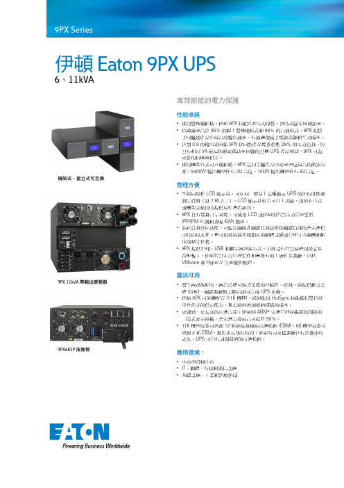
9SX 50009SX 60009PX 50009PX 60009SX EBM 180V9PX EBM 180V安装和用户手册版权所有© 2012 EATON保留所有权利。
服务和支持:请致电您当地的服务代表5-6kVA EU_CN第 2 页5-6kVA EU_CN5-6kVA EU_CN 第 3 页中文安全说明保存这些说明。
本手册包含一些重要说明,在安装和维护 UPS 和电池过程中应加以遵循。
本手册中介绍的 9SX 和 9PX 型号适合安装在温度介于 0°C 到 40°C 之间且不存在导电污染物的环境中。
已对本设备进行测试,且结果符合 FCC 规则第 15部分中规定的关于 A 类数字设备的限制。
这些限制旨在提供合理的保护,以防止设备在商用环境中运行时遭到有害干扰。
此设备会产生、使用且能够辐射射频能量,如果未按照说明手册进行安装和使用,则可能对无线电通信造成有害干扰。
在住宅区域运行此设备可能导致有害干扰,此时用户需要自行支付纠正干扰产生的费用。
认证标准p 安全性: I EC/EN 62040-1/第 1 版:2008. UL 1778 第 4 版p EMC :IEC/EN 62040-2/第 2 版:2006. FCC 第 15部分 A 类。
p 性能: I EC/EN 62040-3/第 2.0版:2011. p IEC 61000-4-2 (ESD):3 级。
p IEC 61000-4-3(辐射场): 3 级。
p IEC 61000-4-4 (EFT):4 级。
p IEC 61000-4-5(快速瞬态): 4 级。
p IEC 61000-4-6(电磁场): 3 级。
p IEC 61000-4-8(导电磁场): 4 级。
特殊符号下面举例介绍了 UPS 或配件上使用的用于警告用户重要信息的符号:存在电击危险 -请遵守与电击危险符号关联的警告。
必须始终遵守的重要说明。

感谢您使用山特产品!请严格遵守本手册和机器上的所有警告及操作说明,并妥善保管本手册。
在没有阅读完所有的安全说明和操作说明以前,请不要操作本机。
严正声明监管码声明为了切实保障您的用电安全,帮助您购买到真正的山特UPS,请注意以下事项:1.认准山特注册商标:、。
2.山特电子(深圳)有限公司在中国从未以任何形式授权委托其它公司生产UPS。
3.山特所有产品机身上均贴有“电子监管码”(“电子监管码”是国家质检总局为打击假货推行的一种产品身份识别码)。
4.消费者可以通过以下途径对产品电子监管码进行查验,并可通过“中国产品质量电子监管网”平台进行投诉、举报。
查询方式:网站查询:登陆(中国产品质量电子监管网),输入监管码进行查询。
电话查询:95001111(未开通地区可拨打114)。
短信查询:将监管码发送至106695001111(移动、联通均可)。
如有疑问,可以拨打电话95001111或登陆 点击“消费者通道”进行举报投诉。
版权声明山特公司致力于技术创新,不断提供更好的产品和服务满足客户需求,对产品设计、技术规格的更新,恕不另行通知,产品以实物为准。
请到山特网站下载最新版本的产品说明书。
版权所有 ©2013-2014 山特电子(深圳)有限公司。
安全注意事项操作安全1.在使用本产品前,请仔细阅读“安全注意事项”,以确保正确和安全的使用。
并请妥善保存说明书。
2.操作时,请注意所有警示标记,并按要求进行操作。
3.避免在阳光直接照射、雨淋或在潮湿的环境使用本设备。
4.本设备不能安装在靠近热源区域,或有电暖炉、热炉等类似的设备附近。
5.放置UPS时,在其四周要留有安全距离,保证通风。
安装时,请参照说明书。
6.清洁时,请使用干燥的物品进行擦拭。
7.若遇火警,请正确使用干粉灭火器进行灭火。
若使用液体灭火器会有触电危险。
电气安全1.上电前,请确认已正确接地,并检查接线和电池极性的连接正确。
2.当UPS需要移动或重新接线时,应将交流输入电源断开,并保证UPS完全停机,否则输出端仍可能带电,有触电的危险。

600KVA大功率模块热插拔网络机房UPS主机技术参数UPS不间断电源系统包含UPS主机和电池两大部分,是机房持续稳定运行的可靠保证,在市电停电的情况下,UPS主机由电池供电,将电池直流电逆变为洁净的交流点输出,为机房IT设备提供可靠电源。
电源系统的设计是机房安全性设计的重中之重,要求采用模块化(N+1)UPS主机2台,目前模块容量150KVA,随着机房设备的增加,UPS模块将逐步扩容,要求单机最大可扩展至300KVA*2。
UPS主机输入/输出电缆按照600KVA容量配置,输入采用(150*4+95*1)*2方电缆输入,输出采用(150*4+95*1)*2输出,以后扩展不需要更换电缆,避免投资浪费。
电池采用电解液采用固体方式12V150AH系列产品,电池配置要求总后备240节12V160AH。
模块UPS系统主机要求UPS必须是高效率、高效能双转换纯在线UPS冗余并联系统(要求主机房两台UPS及相应的配线均能各自独立供电至机柜)。
模块化采用抽屉式高智能模块化设计,由标准机柜、功率模块、监控模块和静态开关模块组合成一台冗余并联UPS。
在整机运行过程中,可以对各个模块进行热插拔操作。
采用标准机柜最多可以安装十个抽屉式UPS 模块,在输出功率允许的情况下,整机可在一至十个模块下正常运行,且能在不影响其他UPS模块工作情况下方便地进行模块增减或更换,无能更换任何模块UPS将在整理、滤波、逆变状态下工作。
单个UPS模块模块容量为30KVA,具有体积小、效率高、绿色环保等优点。
根据不同场合的供电性能要求。
输入功率因数高、电流和谐波小、抗干扰能力强、可靠性强、容量扩展性好等各类优点,可以解决几乎所有的电源问题,如断电、市电高压、市电低压、市电瞬低压、电压瞬时低落、减幅震荡、高压脉冲、电压波动、浪涌电压、谐波失真、杂波干扰、频率波动等电源问题1、UPS系统技术a)UPS必须满足的关键技术参数及要求:模块化(标准机柜式)设计,每个扩展型机柜必须具备标准配置的自动静态旁路,系统还必须具备维修旁路。




Eaton CT06B0108193724800Eaton 9PHD Marine UPS, 60 kVA, 60 kW scalable to 100 kW,Rectifier input switchSingle feed, Internal Maintenance Bypass,Wiring system: 3ph+Gnd, 400V input, 230V Line to Line outputthrough isolation transformerEaton 9PHD Marine UPS CT06B0108193724800937 mm1978 mm1045 mm940 kgIEC/EN 62040-1 IEC/EN 62040-2 IEC/EN 62040-3DNV GL Certified CEProduct Name Catalog Number Product Length/Depth Product Height Product Width Product Weight Compliances Certifications60 Hz50 Hz1Modular97 %TowerFixed connection 380 V480 V50 HzHardwiredIP23Free standing model Yes380 VGray99 %Eaton 9PHD Industrial UPS 20-200 kW CE Declaration of ConformitySecondary Frequency MaxInput frequency - minOutput power factorForm factorOverall efficiencyMounting MethodInput connectionInput voltage - minOutput voltage - maxSecondary Frequency MinExternal battery connectionDegree of ProtectionConstruction typeInternal maintenance bypassOutput voltage - minColorEfficiency (improved efficiency mode)SertifiseringsrapporterTopologyOnlineNumber of output connections fixed connection1kVA rating60 kVAEfficiency (eco-mode)99 %Runtime at half load0 minImproved efficiency modeESS with VMMSInput nominal voltage400V default (380/400/415V)Input frequency - max60 HzNumber Of Output Connections With Protective Contact (Schuko)Input voltage - max480 VPhase (output)3Integrated functionalityNetwork MangementModularAuto shutdown functionYesPotential free switch contactYesApplicationMarinePhase (input)3Package contentsUPSQuickstart guideSafety instructionsOutput effective power60 kWFeed typeACVoltage distortion output (linear load) - max 1 %Hot-swappable power modulesNoOutput apparent power60000 VAParallelableParallel for capacity and redundancyOutput frequency50 Hz (50/60 Hz programmable)Primary frequency - min50 HzAudible alarmsYesType Of InterfaceOtherTypeUPSTransition time for full load0 sBattery charger typeABM technologyRuntime at full load0 minSnmpNoPrimary frequency - max60 HzEaton Corporation plc Eaton House30 Pembroke Road Dublin 4, Ireland © 2023 Eaton. Med enerett. Eaton is a registered trademark.All other trademarks areproperty of their respectiveowners./socialmedia。

Eaton 9SX8KIEaton 9SX UPS, 8 kVA, 7.2 kW, Input: Hardwired, Outputs:Hardwired, Rack/tower, 6UGeneral specificationsEaton 9SX UPS9SX8KI70 cm44 cm26 cm77 kg2 year CE MarkedTUVIEC/EN 62040-1 IEC/EN 62040-2 CEEAC Eaton 9SX 8000iProduct Name Catalog Number Product Length/Depth Product Height Product Width Product Weight Warranty Compliances Certifications Model CodeSealed, lead-acidView runtime graphHot-swappable battery modules 2012 V / 7 AhYes Hardwired230V7.2 kW0.9200/208/220/230/240/250 V +/- 1%Sine wave230V default (200/208/220/230/240/250V) 21Online/Double-conversion8 kVAHardwired/fixed connection230V default (200/208/220/230/240/250V) 50/60 Hz>.99176-276 V (100-276 V with derating)NoBattery typeRuntime graphBattery replacement Battery quantityBattery managementBattery ratingExtended battery capability ReceptacleVoltageWattageOutput power factorOutput voltage rangeOutput waveformOutput nominal voltageVoltage distortion output (linear load) - max Feed typeTopologyVA ratingInput connection Input nominal voltage Nominal frequency Input power factor Input voltage range Includes network card CommunicationABM & Temperaturecompensated chargingmethod (user selectable)Automatic battery testDeep discharge protectionAutomatic recognition ofexternal battery unitsUSB port (HID compliant)Serial port (RS232)Mini terminal block forremote On/OffMini-terminal block forremote power offDry contacts (4 outputs,relay, DB9)40-70 HzNoMultilingual graphical LCD display YesOne slot for optional communication card Eaton Intelligent Power Manager, Eaton Intelligent Power Protector Other3000 m <48 dB at 1 meter 0° to 40°C (32° to 104°F)0-95% non-condensingFree standing model 1YesYes BlackInput frequency range Ethernet interface User interfacePotential free switch contact Expansion slotsSoftware compatibilityType of interface Altitude Noise level Temperature range Relative humidity Construction type Package contents Phase (output)Internal bypass Auto shutdown function Color Power ModuleExtended battery module (EBM)USB cable Serial cableBattery cable with comms for automatic battery cabinet recognition(2) Supports for tower mounting Link plate Safety instructions Quickstart guideEaton Corporation plc Eaton House30 Pembroke Road Dublin 4, Ireland © 2023 Eaton. Alle rettigheder forbeholdes. Eaton is a registered trademark.All other trademarks areproperty of their respective owners./socialmedia95No1NoEU declaration of conformity Eaton 9SX UPSEfficiency Rack mounting kit Phase (input)Hot swap power Compliance information。

电器二次报验单CB18 单元工程施工质量报验单(水利[2010]质报号)合同名称:金钟河防潮闸枢纽拆除重建工程施工合同编号: JZHSG/HT-2009-1枢纽拆除重建工程监理部1#.2#闸门LCU JZH-9-1 合同要求完成施工,检合格,报请贵方核验。
附:1#.2#闸门LCU JZH-9-1 单元工程质量评定表。
说明:本表一式份,由承包人填写。
监理机构审签后,承包人2份,监理机构、发包人各1份。
CB18 单元工程施工质量报验单(水利[2010]质报号)合同名称:金钟河防潮闸枢纽拆除重建工程施工合同编号: JZHSG/HT-2009-1枢纽拆除重建工程监理部3#闸门LCU JZH-9-2 合同要求完成施工,经自检合格,报请贵方核验。
附:3#闸门LCU JZH-9-2 单元工程质量评定表。
说明:本表一式份,由承包人填写。
监理机构审签后,承包人2份,监理机构、发包人各1份。
CB18 单元工程施工质量报验单(水利[2010]质报号)合同名称:金钟河防潮闸枢纽拆除重建工程施工合同编号: JZHSG/HT-2009-1枢纽拆除重建工程监理部4#.5#闸门LCU JZH-9-3合同要求完成施工,经自检合格,报请贵方核验。
附:4#.5#闸门LCU JZH-9-3单元工程质量评定表。
说明:本表一式份,由承包人填写。
监理机构审签后,承包人2份,监理机构、发包人各1份。
CB18 单元工程施工质量报验单(水利[2010]质报号)合同名称:金钟河防潮闸枢纽拆除重建工程施工合同编号: JZHSG/HT-2009-1枢纽拆除重建工程监理部船闸上闸首闸门LCU JZH-9-4合同要求完成施工,经自检合格,报请贵方核验。
附:船闸上闸首闸门LCU JZH-9-4单元工程质量评定表。
说明:本表一式份,由承包人填写。
监理机构审签后,承包人2份,监理机构、发包人各1份。
CB18 单元工程施工质量报验单(水利[2010]质报号)合同名称:金钟河防潮闸枢纽拆除重建工程施工合同编号: JZHSG/HT-2009-1枢纽拆除重建工程监理部船闸下闸首闸门LCU JZH-9-5 合同要求完成施工,经自检合格,报请贵方核验。