CT1504中文资料
- 格式:pdf
- 大小:46.14 KB
- 文档页数:2
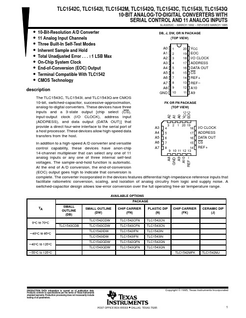
IMPORTANT NOTICETexas Instruments (TI) reserves the right to make changes to its products or to discontinue any semiconductor product or service without notice, and advises its customers to obtain the latest version of relevant information to verify, before placing orders, that the information being relied on is current.TI warrants performance of its semiconductor products and related software to the specifications applicable at the time of sale in accordance with TI’s standard warranty. Testing and other quality control techniques are utilized to the extent TI deems necessary to support this warranty. Specific testing of all parameters of each device is not necessarily performed, except those mandated by government requirements.Certain applications using semiconductor products may involve potential risks of death, personal injury, or severe property or environmental damage (“Critical Applications”).TI SEMICONDUCTOR PRODUCTS ARE NOT DESIGNED, INTENDED, AUTHORIZED, OR WARRANTED TO BE SUITABLE FOR USE IN LIFE-SUPPORT APPLICATIONS, DEVICES OR SYSTEMS OR OTHER CRITICAL APPLICATIONS.Inclusion of TI products in such applications is understood to be fully at the risk of the customer. Use of TI products in such applications requires the written approval of an appropriate TI officer. Questions concerning potential risk applications should be directed to TI through a local SC sales office.In order to minimize risks associated with the customer’s applications, adequate design and operating safeguards should be provided by the customer to minimize inherent or procedural hazards.TI assumes no liability for applications assistance, customer product design, software performance, or infringement of patents or services described herein. Nor does TI warrant or represent that any license, either express or implied, is granted under any patent right, copyright, mask work right, or other intellectual property right of TI covering or relating to any combination, machine, or process in which such semiconductor products or services might be or are used.Copyright © 1995, Texas Instruments Incorporated。
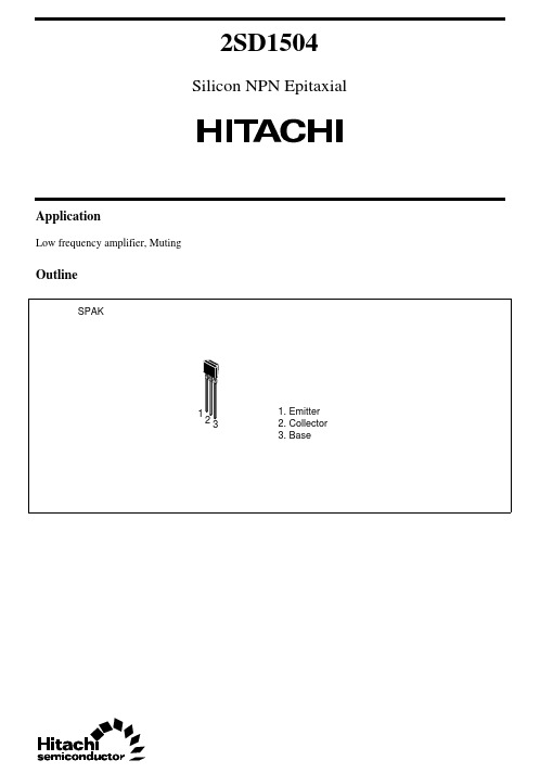
2SD1504Silicon NPN EpitaxialApplicationLow frequency amplifier, MutingOutline2SD15042Absolute Maximum Ratings (Ta = 25°C)ItemSymbol Ratings Unit Collector to base voltage V CBO 30V Collector to emitter voltage V CEO 15V Emitter to base voltage V EBO 5V Collector current I C 0.5A Collector peak current ic (peak) 1.0A Collector power dissipation P C 300mW Junction temperature Tj 150°C Storage temperatureTstg–55 to +150°CElectrical Characteristics (Ta = 25°C)ItemSymbol Min Typ Max Unit Test conditions Collector to base breakdown voltageV (BR)CBO30——V I C = 10 µA, I E = 0Collector to emitter breakdown voltageV (BR)CEO 15——V I C = 1 mA, R BE = ∞Emitter to base breakdown voltageV (BR)EBO 5——V I E = 10 µA, I C = 0Collector cutoff current I CBO ——10µAV CB = 20 V, I E = 0DC current transfer ratio h FE *1250—1200V CE = 1 V, I C = 150 mA*2Base to emitter voltage V BE —0.65—V V CE = 1 V, I C = 150 mA Collector to emitter saturation voltageV CE(sat)—0.150.5V I C = 500 mA, I B = 50 mA*2V CE(sat)—0.018—V I C = 30 mA, I B = 3 mA Gain bandwidth product f T —300—MHz V CE = 1 V, I C = 50 mA On resistancer on—0.5—ΩI B = 2 mANotes: 1.The 2SD1504 is grouped by h FE as follows.2.Pulse test DEF250 to 500400 to 800600 to 12002SD150432SD150442SD15045Unit: mmCautions1.Hitachi neither warrants nor grants licenses of any rights of Hitachi’s or any third party’s patent,copyright, trademark, or other intellectual property rights for information contained in this document.Hitachi bears no responsibility for problems that may arise with third party’s rights, includingintellectual property rights, in connection with use of the information contained in this document.2.Products and product specifications may be subject to change without notice. Confirm that you have received the latest product standards or specifications before final design, purchase or use.3.Hitachi makes every attempt to ensure that its products are of high quality and reliability. However,contact Hitachi’s sales office before using the product in an application that demands especially high quality and reliability or where its failure or malfunction may directly threaten human life or cause risk of bodily injury, such as aerospace, aeronautics, nuclear power, combustion control, transportation,traffic, safety equipment or medical equipment for life support.4.Design your application so that the product is used within the ranges guaranteed by Hitachi particularly for maximum rating, operating supply voltage range, heat radiation characteristics, installationconditions and other characteristics. Hitachi bears no responsibility for failure or damage when used beyond the guaranteed ranges. Even within the guaranteed ranges, consider normally foreseeable failure rates or failure modes in semiconductor devices and employ systemic measures such as fail-safes, so that the equipment incorporating Hitachi product does not cause bodily injury, fire or other consequential damage due to operation of the Hitachi product.5.This product is not designed to be radiation resistant.6.No one is permitted to reproduce or duplicate, in any form, the whole or part of this document without written approval from Hitachi.7.Contact Hitachi’s sales office for any questions regarding this document or Hitachi semiconductor products.Hitachi, Ltd.Semiconductor & Integrated Circuits.Nippon Bldg., 2-6-2, Ohte-machi, Chiyoda-ku, Tokyo 100-0004, Japan Tel: Tokyo (03) 3270-2111 Fax: (03) 3270-5109Copyright ' Hitachi, Ltd., 1999. All rights reserved. Printed in Japan.Hitachi Asia Pte. Ltd.16 Collyer Quay #20-00Hitachi TowerSingapore 049318Tel: 535-2100Fax: 535-1533URLNorthAmerica : http:/Europe : /hel/ecg Asia (Singapore): .sg/grp3/sicd/index.htm Asia (Taiwan): /E/Product/SICD_Frame.htm Asia (HongKong): /eng/bo/grp3/index.htm Japan : http://www.hitachi.co.jp/Sicd/indx.htmHitachi Asia Ltd.Taipei Branch Office3F, Hung Kuo Building. No.167, Tun-Hwa North Road, Taipei (105)Tel: <886> (2) 2718-3666Fax: <886> (2) 2718-8180Hitachi Asia (Hong Kong) Ltd.Group III (Electronic Components)7/F., North Tower, World Finance Centre,Harbour City, Canton Road, Tsim Sha Tsui,Kowloon, Hong Kong Tel: <852> (2) 735 9218Fax: <852> (2) 730 0281 Telex: 40815 HITEC HXHitachi Europe Ltd.Electronic Components Group.Whitebrook ParkLower Cookham Road MaidenheadBerkshire SL6 8YA, United Kingdom Tel: <44> (1628) 585000Fax: <44> (1628) 778322Hitachi Europe GmbHElectronic components Group Dornacher Stra§e 3D-85622 Feldkirchen, Munich GermanyTel: <49> (89) 9 9180-0Fax: <49> (89) 9 29 30 00Hitachi Semiconductor (America) Inc.179 East Tasman Drive,San Jose,CA 95134 Tel: <1> (408) 433-1990Fax: <1>(408) 433-0223For further information write to:。
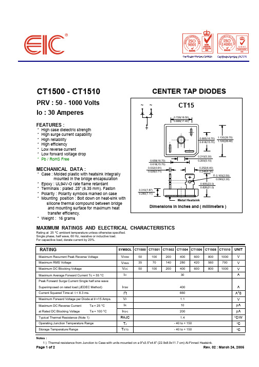
CT1500 - CT1510CENTER TAP DIODESPRV : 50 - 1000 Volts Io : 30 AmperesFEATURES :* High case dielectric strength * High surge current capability * High reliability * High efficiency* Low reverse current* Low forward voltage drop * Pb / RoHS FreeMECHANICAL DATA :* Case : Molded plastic with heatsink integrally mounted in the bridge encapsulation * Epoxy : UL94V-O rate flame retardant * Terminals : plated .25" (6.35 mm). Faston * Polarity : Polarity symbols marked on case* Mounting position : Bolt down on heat-sink with silicone thermal compound between bridge and mounting surface for maximum heat transfer efficiency. * Weight : 16 gramsMAXIMUM RATINGS AND ELECTRICAL CHARACTERISTICSRating at 25 °C ambient temperature unless otherwise specified.Single phase, half wave, 60 Hz, resistive or inductive load. For capacitive load, derate current by 20%.RATINGSYMBOL CT1500CT1501CT1502CT1504CT1506CT1508CT1510UNIT Maximum Recurrent Peak Reverse Voltage V RRM 501002004006008001000V Maximum RMS Voltage V RMS 3570140280420560700V Maximum DC Blocking VoltageV DC 501002004006008001000V Maximum Average Forward Current Tc = 55 °C I O 30A Peak Forward Surge Current Single half sine wave Superimposed on rated load (JEDEC Method)I FSM 400A Current Squared Time at t < 8.3 ms.I 2t 660A 2S Maximum Forward Voltage per Diode at I F =15 Amps.V F 1.1V Maximum DC Reverse Current Ta = 25 °C I R 10µA at Rated DC Blocking Voltage Ta = 100 °C I R(H)200µA Typical Thermal Resistance (Note 1)R θJC 1.4°C/W Operating Junction Temperature Range T J - 40 to + 150°C Storage Temperature RangeT STG- 40 to + 150°CNotes :1 ) Thermal resistance from Junction to Case with units mounted on a 9"x3.5"x4.6" (22.9x8.9x11.7 cm) Al-Finned Heatsink.Page 1 of 2Rev. 02 : March 24, 2005CT15Page 2 of 2Rev. 02 : March 24, 2005。

care (heat them up). Avoid using a hammer and hitting the shaft extension.- For the pinions and pulleys, ensure that the radial force is correct (see selection charts).- Ensure that the voltage is normal and that the transmission is correctly aligned; keep shafts precisely parallel.- For direct sleeve couplings, check the alignment of the axes.NOTE : In the event of prolonged storage, turn by hand before starting so as to avoid damaging the seals.In spite of all the care taken during manufacturing and testing, LEROY-SOMER cannot give a 100 % guarantee that the lubricant will not leak. In the event that these leaks could have serious consequences jeopardising the safety of goods and personnel, it is the installer's respon-sibility to take all the necessary precautions to avoid such consequences.For the motor : See recommendations page 6 ORDERING SPARE PARTSThe following information must be provideda) Information on the gearbox nameplate :1 - Description of gearbox2 - Type of mounting (S baseplate, BS or BDflange form)3 - Position4 - Exact gearbox reduction5 - Manufacturing numberb) Information in the corresponding parts list :- part number and descriptionc) If the motor is coupled to the gearbox, information on the motor plate :(For the motor : see corresponding manual)- motor type- polarity (or speed in min-1)- power in kWCaution : special flange and motor shaft for these gearboxes.similar.- Caution : use the appropriate tools :• hub remover, bearing remover• plastic or leather mallets• correctly sized keys• circlip pliers, gauged screwdrivers(To remove wheel axis 2 , use a hub remover - it is retained on a tapered shaft).- The dismantled parts should be put carefully in order in a clean place.- The flange spigots which ensure watertightness should be cleaned with the scraper.- Retrieve the sealing rings and inspect them for quality; to ensure that they are watertight when reassembled, they should show no sign of pressure, nor breaks or tears.- Systematically replace the lipseals.- Gather together all faulty parts so that replacement parts can be ordered.Reassembly :- Follow the instructions for dismantling in reverse order. - Lightly lubricate the shafts and bearing cages before mounting.- To fit the gear wheels onto the shafts, do not use a hammer. First heat them on a hotplate (or in an oven) to 180 °C (+0, -10). Heat open-type bearings to a maximum of 120°, and sealed bearings to a maximum of 90°.- Oil the lipseals; these should be mounted with care so as not to damage the contact lips; ideally use protective sleeves for the shaft keyways.- The screws and pins should be mounted with a polymer adhesive (for example "normal" Loctite type).- Replace the sealing joints, checking their position carefully.- Fill with oil, up to the level shown (see page 6).- Run the gearbox and inspect its operation before mounting it permanently.052CAUTION :For an order :- for part no. "U" mountspecify the dimensions of motor flange B14 or B5- for part no. "U" shaftspecify the dimensions of the shaft extension- for part no. end gearspecify gear box type 1502, 1503, 1504 and the totalreduction.0080320420320872 - Connection :- Choose cables of sufficient diameter to avoid excessive voltage drops (5 amps per mm2).- Connect the terminals in accordance with the diagram located inside the terminal box.- Follow the wiring diagrams supplied with the units in the terminal boxes and the power supply indicated on the nameplate.Very important : Once connected, the terminal box cover should be carefully replaced. Tighten the cable gland firmly on the power supply cable.Earthing :A terminal is provided inside the terminal box, enabling a conductor to be connected for earthing.hours at 3,000 min-1, 30,000 hours at 1,500 min-1).SINGLE-PHASE MOTORSWITH PERMANENT CAPACITORThese are mechanically identical to three-phase motors. In addition they have 1 permanent capacitor fixed on the side of the terminal box.For connection, apply the voltage indicated on the name-plate and follow the wiring diagrams supplied in the terminal box.LUBRICATION OilsThese gearboxes are permanently greased with synt h e t i c oil. There is only one filler plug.- Original oil :Syntheso HT 220 - Synthetic baseOperating temperature -50 °C to + 150 °CViscosity ISO VG 220Ignition point 250 °CSupplier : KLUBER LUBRICATION - MUNICH RFA - After dismantling :• Suitable replacement oils :any oils with synthetic base for gearinghaving characteristic viscosity equivalentto ISO VG 220 (DIN 51 519)Eg : MOBIL SHC 629 or 634 oilsNote : Do not mix oils; empty the gearbox, wash well, fill with new oil.Filling capacity 450 grs。
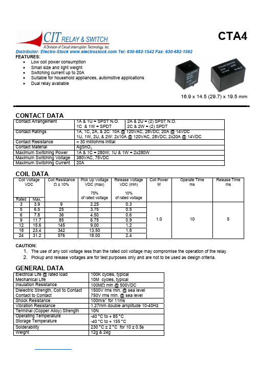
Distributor: Electro-Stock Tel: 630-682-1542 Fax: 630-682-1562 FEATURES:• Low coil power consumption • Small size and light weight • Switching current up to 20A• Suitable for household appliances, automotive applications • Dual relay available 16.9 x 14.5 (29.7) x 19.5 mmCONTACT DATAContact Arrangement 1A & 1U = SPST N.O. 1C & 1W = SPDT 2A & 2U = (2) SPST N.O. 2C & 2W = (2) SPDTContact Ratings1A, 1C, 2A, & 2C: 10A @ 120VAC, 28VDC; 20A @ 14VDC1U, 1W, 2U, & 2W: 2x10A @ 120VAC, 28VDC; 2x20A @ 14VDC Contact Resistance < 30 milliohms initial Contact MaterialAgSnO 2Maximum Switching Power 1A & 1C = 280W; 1U & 1W = 2x280W Maximum Switching Voltage 380VAC, 75VDC Maximum Switching Current 20ACOIL DATACoil VoltageVDCRated Max.Coil ResistanceΩ ± 10%Pick Up Voltage VDC (max)75%of rated voltageRelease Voltage VDC (min)10%of rated voltageCoil PowerWOperate TimemsRelease Timems3 3.9 9 2.25 0.3 5 6.5 25 3.75 0.5 6 7.8 36 4.500.6 9 11.7 85 6.75 0.9 12 15.6 145 9.00 1.2 18 23.4 342 13.50 1.8 24 31.2 576 18.00 2.41.0 10 5CAUTION:1. The use of any coil voltage less than the rated coil voltage may compromise the operation of the relay.2. Pickup and release voltages are for test purposes only and are not to be used as design criteria.GENERAL DATAElectrical Life @ rated load Mechanical Life100K cycles, typical 10M cycles, typical Insulation Resistance100M Ω min @ 500VDCDielectric Strength, Coil to Contact Contact to Contact 1500V rms min. @ sea level 750V rms min. @ sea level Shock Resistance 100m/s 2 for 11msVibration Resistance1.27mm double amplitude 10-40Hz Terminal (Copper Alloy) Strength 10NOperating Temperature Storage Temperature -40 °C to + 85 °C -40 °C to + 155 °CSolderability 230 °C ± 2 °C for 10 ± 0.5s Weight12g & 24gDistributor: Electro-Stock Tel: 630-682-1542 Fax: 630-682-1562 ORDERING INFORMATION1. Series:CTA4CTA42.Contact Arrangement:1A = SPST N.O.1C = SPDT1U = SPST N.O.1W = SPDT2A = (2) SPST N.O.2C = (2) SPDT2U = (2) SPST N.O.2W = (2) SPDT1C3. Sealing Options:S = SealedC = Dust CoverS4. Coil Voltage:3VDC5VDC6VDC9VDC12VDC18VDC24VDC12VDC DIMENSIONS (Units = mm)SINGLE PACKAGE DUAL PACKAGE SCHEMATICS & PC LAYOUTS (BOTTOM VIEWS)1A 1C 1U 1W 2A 2C 2U 2W。
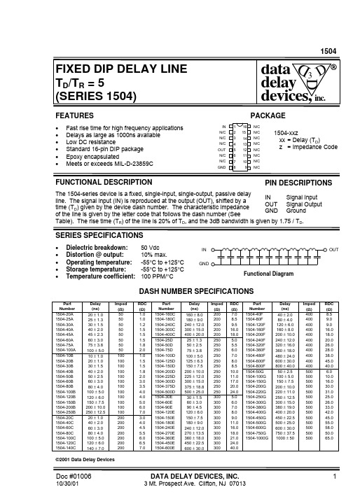
1504Doc #01006DATA DELAY DEVICES, INC.110/30/013 Mt. Prospect Ave. Clifton, NJ 07013FEATURESPACKAGE• Fast rise time for high frequency applications • Delays as large as 1000ns available • Low DC resistance• Standard 16-pin DIP package • Epoxy encapsulated• Meets or exceeds MIL-D-23859CFUNCTIONAL DESCRIPTIONThe 1504-series device is a fixed, single-input, single-output, passive delayline. The signal input (IN) is reproduced at the output (OUT), shifted by atime (T D ) given by the device dash number. The characteristic impedanceof the line is given by the letter code that follows the dash number (SeeTable). The rise time (T R ) of the line is 20% of T D , and the 3dB bandwidth is given by 1.75 / T D .SERIES SPECIFICATIONS• Dielectric breakdown:50 Vdc • Distortion @ output:10% max.• Operating temperature:-55°C to +125°C • Storage temperature:-55°C to +125°C • Temperature coefficient:100 PPM/°CDASH NUMBER SPECIFICATIONSPart Number Delay (ns)Imped (Ω)RDC (Ω)Part Number Delay (ns)Imped (Ω)RDC (Ω)Part Number Delay (ns)Imped (Ω)RDC (Ω)1504-20A 20 ± 1.050 1.01504-160C 160 ± 8.02007.01504-40F 40 ± 2.04008.51504-25A 25 ± 1.350 1.01504-180C 180 ± 9.02008.51504-80F 80 ± 4.04009.01504-30A 30 ± 1.550 1.21504-240C 240 ± 12.02009.51504-120F 120 ± 6.04009.01504-40A 40 ± 2.050 1.51504-300C 300 ± 15.020016.01504-160F 160 ± 8.040016.01504-45A 45 ± 2.350 1.51504-400C 400 ± 20.020018.01504-200F 200 ± 10.040018.01504-60A 60 ± 3.050 1.51504-25D 25 ± 1.3250 5.01504-240F 240 ± 12.040020.01504-75A 75 ± 3.850 1.81504-50D 50 ± 2.5250 5.51504-320F 320 ± 16.040026.01504-100A 100 ± 5.050 2.01504-75D 75 ± 3.8250 6.01504-360F 360 ± 18.040028.01504-10B 10 ± 1.0100 1.01504-100D 100 ± 5.02507.01504-480F 480 ± 24.040038.01504-20B 20 ± 1.0100 1.51504-125D 125 ± 6.32508.01504-600F 600 ± 30.040045.01504-30B 30 ± 1.5100 1.51504-150D 150 ± 7.52508.51504-800F 800 ± 40.040040.01504-40B 40 ± 2.0100 1.81504-200D 200 ± 10.025010.01504-50G 50 ± 2.5500 6.01504-50B 50 ± 2.5100 2.01504-225D 225 ± 12.025011.01504-100G 100 ± 5.050010.01504-60B 60 ± 3.0100 3.01504-300D 300 ± 15.025017.01504-150G 150 ± 7.550016.01504-80B 80 ± 4.0100 3.51504-375D 375 ± 18.825020.01504-200G 200 ± 10.050030.01504-100B 100 ± 5.0100 4.01504-500D 500 ± 25.025024.01504-220G 220 ± 11.050031.01504-120B 120 ± 6.0100 4.01504-30E 30 ± 1.5300 5.01504-250G 250 ± 12.550025.01504-150B 150 ± 7.5100 5.01504-60E 60 ± 3.0300 6.01504-300G 300 ± 15.050026.01504-200B 200 ± 10.0100 6.01504-90E 90 ± 4.53007.01504-380G 380 ± 19.050033.01504-250B 250 ± 12.51007.01504-120E 120 ± 6.03008.01504-400G 400 ± 20.050042.01504-20C 20 ± 1.0200 3.01504-150E 150 ± 7.53009.01504-450G 450 ± 22.550045.01504-40C 40 ± 2.0200 4.01504-180E 180 ± 9.030011.01504-500G 500 ± 25.050055.01504-60C 60 ± 3.0200 4.51504-240E 240 ± 12.030016.01504-600G 600 ± 30.050058.01504-80C 80 ± 4.0200 5.51504-270E 270 ± 13.530018.01504-750G 750 ± 37.550050.01504-100C 100 ± 5.0200 6.01504-360E 360 ± 18.030021.01504-1000G1000 ± 5050065.01504-120C 120 ± 6.0200 6.51504-450E 450 ± 22.530024.01504-140C140 ± 7.02007.01504-600E600 ± 30.030040.0©2001 Data Delay Devicesdevices, inc.316151413121110912345678IN N/C N/C N/C OUT N/C N/C GNDN/C N/C N/C N/C N/C N/C N/C N/C1504-xxzxx = Delay (T D )z = Impedance CodePIN DESCRIPTIONSIN Signal InputOUT Signal OutputGND GroundFunctional DiagramGNDIN OUT1504Doc #01006DATA DELAY DEVICES, INC.210/30/01Tel: 973-773-2299 Fax: 973-773-9672 *.320 MAX for delayslarger than 500ns12345678161514131211109each .100±.010Non-AccumulativeLead Material:Nickel-Iron alloy 42TIN PLATEPackage DimensionsPASSIVE DELAY LINE TEST SPECIFICATIONSTEST CONDITIONSINPUT:OUTPUT:Ambient Temperature:25oC ± 3oCR load :10M ΩInput Pulse:High = 3.0V typical C load :10pfLow = 0.0V typical Threshold:50% (Rising & Falling)Source Impedance:50Ω Max.Rise/Fall Time: 3.0 ns Max. (measured at 10% and 90% levels)Pulse Width (TD <= 75ns):PW IN = 100ns Period(TD <= 75ns):PER IN = 1000ns Pulse Width (TD > 75ns):PW IN = 2 x T D Period(TD > 75ns):PER IN = 10 x T DNOTE:The above conditions are for test only and do not in any way restrict the operation of the device.Timing Diagram For TestingINPUT SIGNALSIGNALINOUTOUTTRIGIN TRIGTest SetupDEVICE UNDER TEST (DUT)OSCILLOSCOPEPULSE GENERATOR50 ΩR OUTR INR IN = R OUT = Z LINE。
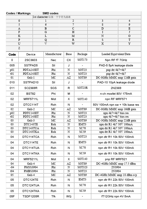
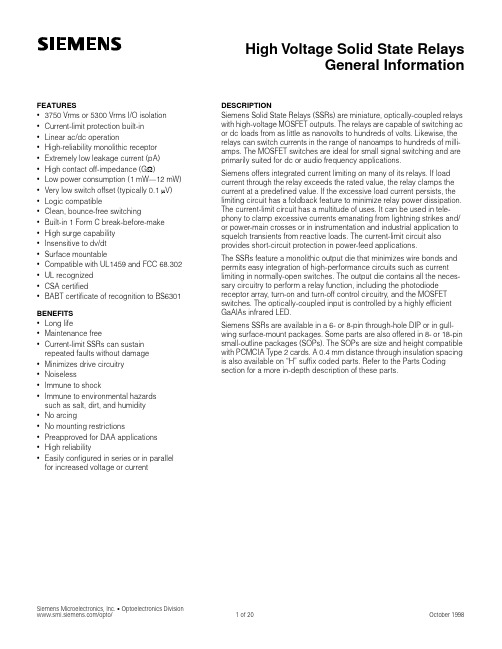
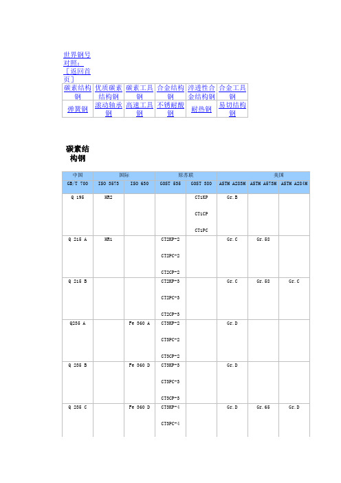
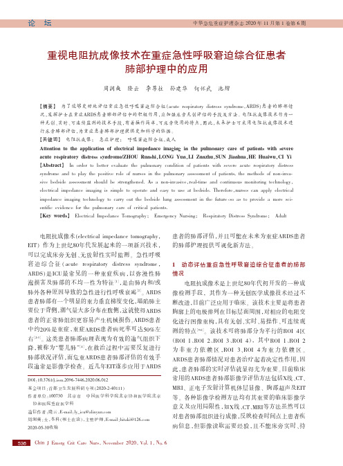
电阻抗成像术(electrical impedance tomography,EIT)作为上世纪80年代发展起来的一项新兴技术,可以完成床旁无创、无放射性实时监测。
急性呼吸窘迫综合征(acute respiratory distress syndrome,ARDS)是ICU最常见的一种重症疾病,以弥漫性肺泡损害及肺部的不均一性为特征[1],是由肺内和/或肺外各种原因导致的急性进行性呼吸衰竭[2]。
ARDS 患者肺部有一个明显的重力垂直梯度变化,塌陷肺主要位于背侧,潮气量大多分布在腹侧,这就使得ARDS 患者的正常肺组织更容易产生机械损伤。
ARDS患者中约20%是重症,重症ARDS患者病死率可达50%左右[2-3]。
这类患者肺部病理表现为有效的通气组织下降,被称为“婴儿肺”[4],在救治过程中需要反复进行肺部状况评估,而危重ARDS患者肺部评估的有效手段通常是影像学检查。
近几年EIT逐步应用于ARDS 患者的肺部评估,并且可能在未来为重症ARDS患者的肺部护理提供可视化新方法。
1动态评估重症急性呼吸窘迫综合征患者的肺部情况电阻抗成像术是上世纪80年代初开发的一种成像检测手段,其作为一种无创医学成像技术经过不断改进,目前广泛应用于临床。
该技术主要是将患者胸廓上的电极排列在目标层面周围,对相应的电阻变化进行图像重构,具有无创、实时、易操作、可连续观测的特点[5-6]。
该技术可将肺部分为平行的ROI4区(ROI1、ROI2、ROI3、ROI4),其中ROI1、ROI2为非重力依赖区,ROI3、ROI4为重力依赖区。
ARDS患者肺部情况对患者治疗起着决定性作用,因此,患者肺部的实时评估就显得尤为重要。
目前临床常用的ARDS患者肺部影像学评估方法包括X线、CT、MRI、正电子发射计算机体层显像、胸部超声及EIT 等。
各种影像学检测方法均有其重要的临床影像学意义及应用局限性,如X线、CT、MRI等方法虽然可以对患者肺部组织进行成像,反映检查时间点上患者疾病信息,但影像读取需要经验,且不能床旁实时、持重视电阻抗成像技术在重症急性呼吸窘迫综合征患者肺部护理中的应用周润奭隆云李尊柱孙建华何怀武池熠【摘要】为了能够更好地评估重症急性呼吸窘迫综合征(acute respiratory distress syndrome,ARDS)患者的肺部情况,发挥护士在重症ARDS患者肺部评估中的积极作用,应加强床旁无创评估的手段及方法。
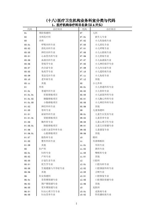
(十八)医疗卫生机构业务科室分类与代码1、医疗机构诊疗科目名录(以A开头)代码诊疗科目代码诊疗科目01 预防保健科07 儿科02 全科医疗科07.01 新生儿专业03 内科07.02 小儿传染病专业03.01 呼吸内科专业07.03 小儿消化专业03.02 消化内科专业07.04 小儿呼吸专业03.03 神经内科专业07.05 小儿心脏病专业03.04 心血管内科专业07.06 小儿肾病专业03.05 血液内科专业07.07 小儿血液病专业03.06 肾病学专业07.08 小儿神经病学专业03.07 内分泌专业07.09 小儿内分泌专业03.08 免疫学专业07.10 小儿遗传病专业03.09 变态反应专业07.11 小儿免疫专业03.10 老年病专业07.12 其他03.11 其他08 小儿外科04 外科08.01 小儿普通外科专业04.01 普通外科专业08.02 小儿骨科专业04.01.01 肝脏移植项目08.03 小儿泌尿外科专业04.01.02 胰腺移植项目08.04 小儿胸心外科专业04.01.03 小肠移植项目08.05 小儿神经外科专业04.02 神经外科专业08.06 其他04.03 骨科专业09 儿童保健科04.04 泌尿外科专业09.01 儿童生长发育专业04.04.01 肾脏移植项目09.02 儿童营养专业04.05 胸外科专业09.03 儿童心理卫生专业04.05.01 肺脏移植项目09.04 儿童五官保健专业04.06 心脏大血管外科专业09.05 儿童康复专业04.06.01 心脏移植项目09.06 其他04.07 烧伤科专业10 眼科04.08 整形外科专业11 耳鼻咽喉科04.09 其他11.01 耳科专业05 妇产科11.02 鼻科专业05.01 妇科专业11.03 咽喉科专业05.02 产科专业11.04 其他05.03 计划生育专业12 口腔科05.04 优生学专业12.01 口腔内科专业05.05 生殖健康与不孕症专业12.02 口腔颌面外科专业05.06 其他12.03 正畸专业06 妇女保健科12.04 口腔修复专业06.01 青春期保健专业12.05 口腔预防保健专业06.02 围产期保健专业12.06 其他06.03 更年期保健专业13 皮肤科06.04 妇女心理卫生专业13.01 皮肤病专业06.05 妇女营养专业13.02 性传播疾病专业06.06 其他13.03 其他医疗机构诊疗科目名录(续)代码诊疗科目代码诊疗科目14 医疗美容科31 病理科15 精神科32 医学影像科15.01 精神病专业32.01 X线诊断专业15.02 精神卫生专业32.02 CT诊断专业15.03 药物依赖专业32.03 磁共振成像诊断专业15.04 精神康复专业32.04 核医学专业15.05 社区防治专业32.05 超声诊断专业15.06 临床心理专业32.06 心电诊断专业15.07 司法精神专业32.07 脑电及脑血流图诊断专业15.08 其他32.08 神经肌肉电图专业16 传染科32.09 介入放射学专业16.01 肠道传染病专业32.10 放射治疗专业16.02 呼吸道传染病专业32.11 其他16.03 肝炎专业50 中医科16.04 虫媒传染病专业50.01 内科专业16.05 动物源性传染病专业50.02 外科专业16.06 蠕虫病专业50.03 妇产科专业16.07 其它50.04 儿科专业17 结核病科50.05 皮肤科专业18 地方病科50.06 眼科专业19 肿瘤科50.07 耳鼻咽喉科专业20 急诊医学科50.08 口腔科专业21 康复医学科50.09 肿瘤科专业22 运动医学科50.10 骨伤科专业23 职业病科50.11 肛肠科专业23.01 职业中毒专业50.12 老年病科专业23.02 尘肺专业50.13 针灸科专业23.03 放射病专业50.14 推拿科专业23.04 物理因素损伤专业50.15 康复医学专业23.05 职业健康监护专业50.16 急诊科专业23.06 其他50.17 预防保健科专业24 临终关怀科50.18 其他25 特种医学与军事医学科51 民族医学科26 麻醉科51.01 维吾尔医学27 疼痛科51.02 藏医学28 重症医学科51.03 蒙医学30 医学检验科51.04 彝医学30.01 临床体液、血液专业51.05 傣医学30.02 临床微生物学专业51.06 其他30.03 临床生化检验专业52 中西医结合科30.04 临床免疫、血清学专业69 其他业务科室30.05 临床细胞分子遗传学专业30.06 其他2、疾病预防控制中心业务科室分类与代码(以B开头)代码科室名称代码科室名称01 传染病预防控制科(中心) 11 农村改水技术指导科(中心)02 性病艾滋病预防控制科(中心) 12 疾病控制与应急处理办公室03 结核病预防控制科(中心) 13 食品卫生科04 血吸虫预防控制科(中心) 14 环境卫生所05 慢性非传染性疾病预防控制科(中心) 15 职业卫生科06 寄生虫病预防控制科(中心) 16 放射卫生科07 地方病控制科(中心) 17 学校卫生科08 精神卫生科(中心) 18 健康教育科(中心)09 妇幼保健科19 预防医学门诊10 免疫规划科(中心) 69 其他业务科室3、卫生监督机构业务科室分类与代码(以C开头)代码科室名称代码科室名称01 综合卫生监督科07 稽查科(大队)02 产品卫生监督科08 许可受理科03 职业卫生监督科09 放射卫生监督科04 环境卫生监督科10 学校卫生监督科05 传染病执法监督科11 食品安全监督科06 医疗服务监督科69 其他4、卫生机构管理科室分类与代码(以D开头)代码科室名称代码科室名称71 护理部85 信息科(中心)72 药剂科(药房) 86 医政科73 感染科87 教育培训科81 办公室88 总务科82 人事科89 新农合管理办公室83 财务科99 其他科室84 设备科欢迎您的下载,资料仅供参考!致力为企业和个人提供合同协议,策划案计划书,学习资料等等打造全网一站式需求。
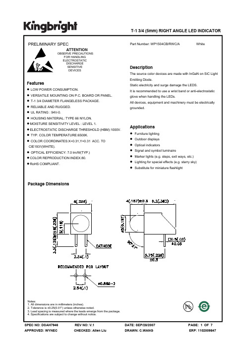
T-1 3/4 (5mm) RIGHT ANGLE LED INDICATOR PRELIMINARY SPECFeaturesParameterSymbol Value Unit Power dissipation P t 120 mW Reverse Voltage V R 5 V Junction temperature T J 110 °C Operating Temperature Top -40 To +85 °C Storage Temperature Tstg -40 To +100°C DC Forward Current I F30 mA Peak Forward CurrentNote4I FM 100 mA Thermal resistanceJunction/ambientNote5R th JA350°C/WAbsolute Maximum Ratings at T A =25°CElectrical / Optical Characteristics at T A =25°CParameterSymbol Value Unit Chromaticity coordinate x acc.to CIE1931I F =20mA [Typ.] X Note10.31 - Chromaticity coordinate y acc.to CIE1931I F =20mA [Typ.]YNote10.31 -Forward Voltage I F =20mA [Min.] V FNote22.7VForward Voltage I F =20mA [Typ.] 3.2 Forward Voltage I F =20mA [Max.] 4.0 Reverse Current (V R =5V) [Typ.] I R 0.01 μAReverse Current (V R =5V) [Max.] 10 Temperature coefficient of xI F =20mA, -10°C ≤ T ≤100°C [Typ.] TC x -0.1 10-3 /°C Temperature coefficient of yI F =20mA, -10°C ≤ T ≤100°C [Typ.] TCy -0.2 10-3 /°C Temperature coefficient of V FI F =20mA, -10°C ≤ T ≤100°C [Typ.]TC V-2.5mV/°CNotes:1.θ1/2 is the angle from optical centerline where the luminous intensity is 1/2 the optical centerline value.2.Luminous intensity is measured by a current pulse of 10ms at a tolerance of ±15%.3.The typical data of Luminous Flux can only reflect statistical figures, actual parameters of individual product could differ from the typical data. For the purpose of product enhancement, the typical data is subject to change without prior notice.4.1/10 Duty Cycle, 0.1ms Pulse Width.5.Rth(J-A) Results from mounting on PC board FR4 (pad size ≥16 mm 2 per pad),Notes:1.Chromaticity coordinates are measured by a current pulse of 20ms with a tolerance of ±0.02 in X and Y color coordinates.2.Forward voltage is measured with a current pulse of 10ms at a tolerance of ±0.1V.Selection GuidePart No.DiceLens Typeluminous Intensity Note2Iv(mcd) @ 20 mAΦv (mlm)Note3@ 20 mA ViewingAngle Note1Min.Typ. Typ. 2θ1/2 WP1504CB/RWC/AWHITE (InGaN) WATER CLEAR48085045020°。
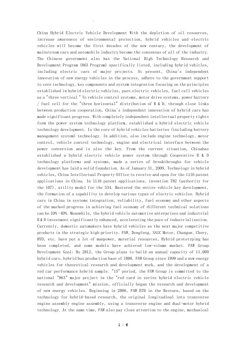
China Hybrid Electric Vehicle Development With the depletion of oil resources, increase awareness of environmental protection, hybrid vehicles and electric vehicles will become the first decades of the new century, the development of mainstream cars and automobile industry become the consensus of all of the industry. The Chinese government also has the National High Technology Research and Development Program (863 Program) specifically listed, including hybrid vehicles, including electric cars of major projects. At present, China's independent innovation of new energy vehicles in the process, adhere to the government support to core technology, key components and system integration focusing on the principles established in hybrid electric vehicles, pure electric vehicles, fuel cell vehicles as a "three vertical " To vehicle control systems, motor drive systems, power battery / fuel cell for the "three horizontal" distribution of R & D, through close links between production cooperation, China's independent innovation of hybrid cars has made significant progress. With completely independent intellectual property rights form the power system technology platform, established a hybrid electric vehicle technology development. Is the core of hybrid vehicles batteries (including battery management system) technology. In addition, also include engine technology, motor control, vehicle control technology, engine and electrical interface between the power conversion and is also the key. From the current situation, Chinahas established a hybrid electric vehicle power system through Cooperative R & D technology platforms and systems, made a series of breakthroughs for vehicle development has laid a solid foundation. As of January 31, 2009, Technology in hybrid vehicles, China Intellectual Property Office to receive and open for the 1116 patent applications in China. In 1116 patent applications, invention 782 (authority for the 107), utility model for the 334. Mastered the entire vehicle key development, the formation of a capability to develop various types of electric vehicles. Hybrid cars in China in systems integration, reliability, fuel economy and other aspects of the marked progress in achieving fuel economy of different technical solutions can be 10% -40%. Meanwhile, the hybrid vehicle automotive enterprises and industrial R & D investment significantly enhanced, accelerating the pace of industrialization. Currently, domestic automakers have hybrid vehicles as the next major competitive products in the strategic high priority, FAW, Dongfeng, SAIC Motor, Changan, Chery, BYD, etc. have put a lot of manpower, material resources, Hybrid prototyping has been completed, and some models have achieved low-volume market. FAW Group Development Goal: By 2012, the Group plans to build an annual capacity of 11,000 hybrid cars, hybrid bus production base of 1000. FAW Group since 1999 and a new energy vehicles for theoretical research and development work, and the development of a red car performance hybrid sample. "15" period, the FAW Group is committed to the national "863" major project in the "red card in series hybrid electric vehicle research and development" mission, officially began the research and development of new energy vehicles. Beginning in 2006, FAW B70 in the Besturn, based on the technology for hybrid-based research, the original longitudinal into transverse engine assembly engine assembly, using a transverse engine and dual-motor hybrid technology. At the same time, FAW also pay close attention to the engine, mechanicaland electrical integration, transmission, vehicle control networks, vehicle control systems development, the current FAW hybrid electric car has achieved 42% fuel saving effect, reached the international advanced level. Jiefang CA6100HEV Hybrid Electric Bus FAW "Liberation brand CA6100HEV Hybrid Electric Bus" project is a national "863" electric vehicle major projects funded project, with pure electric drive, the engine alone drives (and charge), the joint drive motor starts the engine, and sliding regenerative braking 5 kinds of basic operation. The power hybrid electric bus and economy to the leading level, 38% fuel economy than traditional buses, emissions reduced by 30%. Red Flag CA7180AE hybrid cars Red Flag hybrid cars CA7180AE according to the national "863 Plan" is the first in complete with industrial prospects of the car, it is built on the basis of red car with good performance and operational smoothness. Series which is a hybrid sedan, the luxury car ,0-100km acceleration time of 14s, fuel-effici ent than traditional cars by about 50%, Euro Ⅲ emission standard. Besturn B70 hybrid cars Besturn B70 Hybrid cars using petrol - electric hybrid approach. Dual motor power system programs, mixed degree of 40/103, is all mixed (Full-Hybrid, also known as re-mixed) configurations. Besturn B70 Hybrid cars are petrol version costs two to three times Besturn models, mass production will be gradually reduced after the costs, even if this hybrid version Besturn market, the price certainly higher than the existing Besturn models, but high the price of petrol will not exceed 30% version of Besturn models. SAIC Development Goals: 2010 launch in the mixed hybrid cars, plug-in 2012, SAIC strong mix of cars and pure electric cars will be on the market. In the R & D on new energy vehicles, SAIC made clear to focus on hybrid, fuel cell for the direction, and speed up the development of alternative products. Hybrid vehicles, fuel cell vehicles, alternative fuel vehicles as a new energy strategy SAIC three key. 2010 SAIC Roewe 750 hybrid cars in the mix will be put on the market, during the World Expo in Shanghai, SAIC will put 150 hybrid cars in the Expo Line on the River Run. 2012 Roewe 550 plug-in hybrid cars will be strong market, the current car's power system has been launched early development and progress. Apply the new hybrid bus moving on the 1st Apply the new hybrid bus moving on the 1st Academy of Engineering by the SAIC and ShanghaiJiaotongUniversity and other units jointly developed with independent intellectual property rights. Existing cities in the Sunwin Bus Power platform, "the new dynamic application No. 1" uses a parallel hybrid electric vehicle drive program, so that hybrid electric vehicle operating conditions in the electric air-conditioning, steering, braking and other accessories still able to work without additional electric system, while use of super capacitors, to improve starting power, braking energy recovery efficiency, thereby enhancing vehicle dynamic performance, reduce fuel consumption. Car length 10m, width 2.5m, high-3.2m, can accommodate 76 people. Roewe 750 hybrid cars Roewe 750 hybrid cars in the mixed system with BSG (Belt drive start generating one machine), with "smart stop zero-emission" and "environmental protection and the power of both the" two prominent features of a top speed of 205 km / h, the maximum added driving range of up to 500 km. As for the industrialization of SAIC's first own-brand hybrid car, the Roewe 750 hybrid integrated hybrid fuel-efficient cars can achieve rates of around 20%. DongfengMotor Group Development Goals: Plans move into 33 billion in 10 years to develop a range of environmentally friendly hybrid vehicles, including cars. EQ7200HEV hybrid cars EQ7200HEV hybrid cars are "863" project of major projects and major strategic projects of Dongfeng Motor Corporation. The car is EQ7200-Ⅱ model (Fengshen Bluebird cars) is based on an electronically controlled automatic transmission with innovative electromechanical coupling in parallel programs, configure DC brushless motor and nickel-hydrogen batteries, plans to "10 5 "during the industrialization. Industrialization, the vehicle cost more than EQ7200 cars increase in costs ≤ 30%. EQ61100HEV Hybrid Electric Bus EQ61100HEV electric hybrid bus by Dongfeng Vehicle Company Limited Joint Beijing Jiaotong University, Beijing, China Textile Co., Ltd. and Hunan sharp Electromechanical Technology Co., Ltd. jointly developed Shenzhou. EQ61100HEV hybrid electric bus with switched reluctance motor, Cummins ISBe1504 cylinder common rail electronic injection diesel engine, new chassis design of the system, electronically controlled automatic transmission and innovative electromechanical coupling parallel program. In the annual output reached 200, the vehicle cost more than the increase in automobile engine equipped with 6CT ≤ 30%. China Changan Development Goals: the next three years, the formation of different grades, different purposes, carry a different system of mixed platforms, weak mix of scale, strong mixed industrial R & D capabilities, covering commercial, A grade, B grade, C grade products. 2014 will achieve sales of new energy vehicles 150 000 2020 sales of new energy vehicles for more than 500,000. "Eleventh Five-Year Plan" period, Chang-an increased investment in clean energy vehicles, a diversified energy technologies to carry out exploratory research. Environmental protection through energy-saving models continues to introduce new technology to lead the industry to upgrade and fully utilize and mobilize global resources, Chang'an in the middle hybrid cars, hybrid cars and other technological strength of the field are explored. Chang's first hybrid car long Anjie Xun HEV was successfully listed in June 2009; the first batch of 20 hybrid taxis Long An Zhixiang in January of this year officially put into operation in Chongqing. Chery Development Goals: after 2010, more than half of Chery's products carry different levels of hybrid systems. From 2003 to 2008, mainly mixed with moderate Chery hybrid cars and energy saving system development, and industrialization; Chery in Wuhu, a taxi has been carried out on probation, fuel consumption will be reduced by 10% to 30% to reach Europe Ⅳ Standard. Since 2004, Chery hybrid cars mainly for the development of strong and industrialization. Chery hybrid car fuel consumption target to reach 100 km 3 liters, to reach Europe and the United States emissions regulations. Chery A5BSG Chery A5BSG is a weak parallel hybrid electric car, using fuel engines, electric engines complementary mode, the two different power sources in the car while driving to work together or separately, through this combination to achieve the least fuel consumption and exhaust emissions, in order to achieve fuel efficiency and environmental protection purposes. Compared with the conventional car, the car in urban conditions can save 10% -15% of fuel and reduce carbon dioxide emissions by about 12%, while costs increased by only about 25% -30%. Chery A5ISG Chery A5 ISG hybrid power system consists of "1.3L gasoline engine + 5-speed manual transmission+10 kW motor +144 V Ni-MH battery," the composition of the battery system used by the Johnson Controls developed "plug-in" nickel metal hydride (Ni-MH), motor with permanent magnet synchronous motor and with the motor control system, inverter and DC / DC converters. The system enables the vehicle power to 1.6L displacement level and rate of 30% fuel savings and significantly reduce the emissions of Euro V standards. Cherry A3ISG Chery A3 ISG has 1.3L473F gasoline engine and equipped with 10KW motor. By gasoline engines and electric motors with torque overlay approach to dynamic mixed to provide the best vehicle power operating efficiency and energy saving environmental protection goals. Chery A3 ISG also has Stop_Restart the idling stop function such as flame start to start (BSG function), to reduce red light in the vehicle stopped or suspended when the fuel consumption and emissions expenses. FY 2BSG FY 2 BSG carry 1.5LSQR477F inline four-cylinder engine configuration BSG start / stop and so one electric motor, red light in the vehicle stopped the driver into the gap, it will automatically enter standby mode to turn off the engine, starting moments after the entry block automatically start the engine. FY 2 BSG vehicle average fuel consumption than the 1.5L petrol cars reduce about 5-10%, average fuel consumption can be reduced up to 15%. BYD Auto Development Goal: to electric cars as a transitional mode, the electric car as the ultimate goal, the development of new energy cars BYD. BYD follow the "independent research and development, independent production, independent brand" development path, and the "core technology, vertical integration" development strategy, as the transition to dual-mode electric vehicles, electric vehicles as the ultimate goal, the development of BYD new energy vehicles.国混合动力汽车开展随着石油资源的枯竭、人们环保意识的提高,混合动力汽车及电动汽车将成为新世纪前几十年汽车开展的主流,并成为我国汽车界所有业人士的共识。
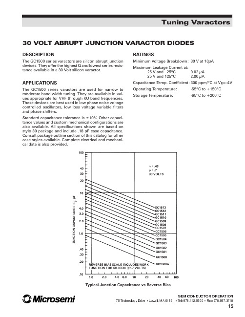
30VOLT ABRUPT JUNCTION VARACTOR DIODESDESCRIPTIONThe GC1500series varactors are silicon abrupt junction devices.They offer the highest Q and lowest series resis-tance available in a 30Volt silicon varactor.APPLICATIONSThe GC1500series varactors are used for narrow tomoderate band width tuning.They are available in val-ues appropriate for VHF through KU band frequencies.These devices are best used in low phase noise voltage controlled oscillators,low loss voltage variable filters and phase shifters.Standard capacitance tolerance is ±10%Other capaci-tance values and custom mechanical configurations are also available.All specifications shown are based on style 30package and include .18pF case capacitance.Consult package outline section of this catalog for other case styles plete electrical and mechani-cal data is alsoprovided.RATINGSMinimum Voltage Breakdown:30V at 10µA Maximum Leakage Current at:25V and 25ºC 0.02µA 25V and 125ºC 2.00µACapacitance-Temp.Coefficient:300ppm/ºC at V R =-4V Operating Temperature:-55ºC to +150ºC Storage Temperature:-65ºC to +200ºCTuning Varactors30VOLT ABRUPT JUNCTION VARACTOR DIODESELECTRICAL SPECIFICATIONS:T A =25°CNOTES:1.When ordering,specify the desired case style by adding its number as a suffix to the model number.Some limitations apply -consult factory for details.2.These values include a package capacitance of .18P ..3.Q is calculated from:Q=1π5jwhere f=50MHz and R I =Series resistance measured a 1GHz using transmission loss techniques.Capacitance is measured at 1MHz.4.GC1500A only available in Die Form.SEMICONDUCTOR OPERATION75T echnology Drive Lowell,MA 01851 T el:978-442-5600 Fax:978-937-374816Tuning Varactors。
CT1500 - CT1510
CENTER TAP DIODES
PRV : 50 - 1000 Volts Io : 30 Amperes
FEATURES :
* High case dielectric strength * High surge current capability * High reliability * High efficiency
* Low reverse current
* Low forward voltage drop * Pb / RoHS Free
MECHANICAL DATA :
* Case : Molded plastic with heatsink integrally mounted in the bridge encapsulation * Epoxy : UL94V-O rate flame retardant * Terminals : plated .25" (6.35 mm). Faston * Polarity : Polarity symbols marked on case
* Mounting position : Bolt down on heat-sink with silicone thermal compound between bridge and mounting surface for maximum heat transfer efficiency. * Weight : 16 grams
MAXIMUM RATINGS AND ELECTRICAL CHARACTERISTICS
Rating at 25 °C ambient temperature unless otherwise specified.Single phase, half wave, 60 Hz, resistive or inductive load. For capacitive load, derate current by 20%.
RATING
SYMBOL CT1500CT1501CT1502CT1504CT1506CT1508CT1510UNIT Maximum Recurrent Peak Reverse Voltage V RRM 501002004006008001000V Maximum RMS Voltage V RMS 3570140280420560700V Maximum DC Blocking Voltage
V DC 50
100
200
400
600
800
1000
V Maximum Average Forward Current Tc = 55 °C I O 30
A Peak Forward Surge Current Single half sine wave Superimposed on rated load (JEDEC Method)I FSM 400A Current Squared Time at t < 8.3 ms.
I 2
t 660A 2S Maximum Forward Voltage per Diode at I F =15 Amps.V F 1.1V Maximum DC Reverse Current Ta = 25 °C I R 10µA at Rated DC Blocking Voltage Ta = 100 °C I R(H)200µA Typical Thermal Resistance (Note 1)R θJC 1.4°C/W Operating Junction Temperature Range T J - 40 to + 150°C Storage Temperature Range
T STG
- 40 to + 150
°C
Notes :
1 ) Thermal resistance from Junction to Case with units mounted on a 9"x3.5"x4.6" (22.9x8.9x11.7 cm) Al-Finned Heatsink.
Page 1 of 2Rev. 02 : March 24, 2005
CT15
Page 2 of 2Rev. 02 : March 24, 2005。