RJ6F503;RJ6P100;RJ6P101;RJ6P102;RJ6P103;中文规格书,Datasheet资料
- 格式:pdf
- 大小:153.92 KB
- 文档页数:5

专利名称:Installation device null of发明人:松下 国生,小泉 英明,川口 博,黒田 猪三男申请号:JP特願平2-123640申请日:19900514公开号:JP特公平7-94923B2公开日:19951011专利内容由知识产权出版社提供摘要:PURPOSE:To prevent an air conditioner from falling off and facilitate installation of the air conditioner, by a construction wherein a fastening piece having a reverse L-shaped hook part is provided at either one of an upper end of an installing plate and an upper part of a back face of a main body of the air conditioner, and a notched part for engagement with the hook part is provided in the other of the two members. CONSTITUTION:At the time of installing an air conditioner, an installing plate 2 is attached to a wall surface 3, engaging recessed parts 7 of a main body 1 of the air conditioner are hooked on support arms 5 of the plate 2, and support pieces 8 provided at lower parts of the main body 1 are attached to receiving pieces 6 of the plate 2 by screws 9, whereby the air conditioner can be mounted on the wall surface 3 in a vertical position. At the time of connecting a piping, a lower part of the main body 1 of the air conditioner is lifted up by using contact parts between the arms 5 and the recessed parts 7 as a fulcrum, to provide an appropriate spacing between the main body 1 and the installing plate 2, and a piping 10 is connected. A reverse Lshaped fastening piece 13 of the plate 2 is located above the fulcrum, so that when the lower part of the main body 1 is lifted up to a certain level, the fastening piece 13 is engaged with a notched part 16 in a back face 1a of the main body 1 to prevent the recessed parts 7 from being disengagedfrom the arms 5.申请人:三菱電機株式会社地址:東京都千代田区丸の内2丁目2番3号国籍:JP代理人:高田 守 (外1名)更多信息请下载全文后查看。

1本系列产品,是在该公司研制的专用超大规模集成电路的基础上,研发的点对点光传输设备。
此款产品提供1-16路电话接口;2路以太网接口(以太网带宽为线速100M);设备内部电路部分采用全数字电路,整机工作可靠、稳定,功耗低,集成度高,体积小,易于安装维护。
基于自主知识产权的集成电路;语音口支持FXO/FXS,FXO 口与程控交换机对接,FXS 口与用户的电话机相连;FXO/FXS 电话接口,支持来电显示功能/反极性计费/传真功能;电话接口支持两边站点的相互放号功能; 2路以太网接口10M/100M,全/半双工完全自适应,每路以太网口支持Auto-MDIX(交叉/直连线自适应),带宽线速100M(100M 吞吐量测试零丢包);多种电源方式可选:AC220V、DC-48V/DC24V 等;支持AC+DC;AC+AC;DC+DC 等双电源备份模式; 电话接口带防雷保护,防雷达到GB/T17626.5(IEC61000-4-5)短路电流波10/700μs 开路峰值输出电压6KV 标准。
◆光纤部分光口:1光纤:单纤/双纤光纤接口:FC/SC/ST/LC(SFP)波长:850nm/1310nm 多模;1310nm/1550nm 单模无中继传输距离:0~2Km(多模);20~120Km(单模)典型发射功率:单模1310/1550nm:≥-9dBm多模850nm:-18dBm多模1310nm:-25dBm接受灵敏度范围:-28dBm~-40dBm◆FXS用户电话口振铃电压:75V振铃频率:25Hz二线输入阻抗:600Ω(摘机)回损:20dB◆FXO中继口振铃检测电压:35V振铃检测频率:17Hz-60Hz二线输入阻抗:600Ω(摘机)回损:20dB◆10/100M以太网接口协议:符合IEEE802.3,IEEE802.1Q(VLAN)速率:10/100M自适应,全/半双工完全自适应MAC地址表:可以学习4096个MAC地址物理接口:RJ45座,支持Auto-MDIX(交叉/直通线自适应)◆电气和机械特性系统电源:AC180V~260V;DC–48V;DC+24V功耗:≤5W外观结构:(长×宽×高)485*138*45mm机架式◆环境指标工作温度:-10℃—+60℃储存温度:-40℃—+85℃工作湿度:0%—95%(无凝结)MTBF:>100,000小时23产品名称16路电话+2路以太网光端机产品功能描述在光纤上传输16路电话(RJ11)+2路以太网,19英寸机架式,-48V 或AC220V 电源(可选)业务端口描述1个光口;16路电话接口,2个百兆以太接口;电源AC220V 或DC-48V(电源可选),支持电源冗余备份产品尺寸(长×宽×高)485*137*45mm 机架式重量2Kg/台方案:飞畅科技专注光纤通信研发、生产、销售20年,为客户提供个性化技术服务与定制解决方案。
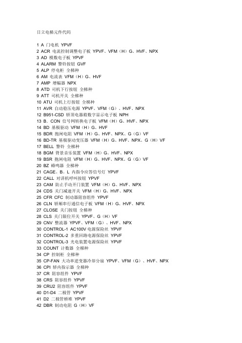
日立电梯元件代码1 A 门电机YPVF2 ACR 电流控制调整电子板YPVF、VFM(H)G、HVF、NPX3 AD 模数电子板YPVF4 ALARM 警铃按钮GVF5 ALP 停电柜全梯种6 AM 电流表VFM(H)G、HVF7 AMP 增幅器NPX8 ATD 司机下行按钮全梯种9 ATT 司机开关全梯种10 ATU 司机上行按钮全梯种11 AVR 自动稳压电源YPVF、VFM(G)、HVF、NPX12 B951-CSD 轿顶电器箱数字显示电子板NPH13 B.CON 信号网转换电子板VFM(H)G、HVF、NPX14 BD 基极驱动VFM(H)G、HVF15 BDR 抱闸电阻VFM(H)G、HVF、NPX、G(G)VF16 BD-TR 基极驱动变压器VFM(H)G、HVF、NPX、G(H)VF17 BELL 警铃全梯种18 BGM 背景音乐装置VFM(H)G、HVF、NPX19 BSR 抱闸电阻VFM(H)G、HVF、NPX、G(G)VF20 BZ 蜂鸣器全梯种21 CAGE。
B。
L 内指令应答信号灯YPVF22 CALL 对讲机呼叫按钮YPVF23 CAM 防止手动开门装置VFM(H)G、HVF、NPX24 CDS 关门减速开关VFM(H)G、HVF、NPX25 CFR CFC 制动器阻容组件YPVF26 CLN 轿厢串行通信电子板VFM(H)G、HVF、NPX27 CLOSE 关门按钮全梯种28 CLS 关门限位开关YPVF、G(H)VF29 CNV 整流器YPVF、VFM(G)、HVF、NPX30 CONTROL-1 AC100V电源保险丝YPVF31 CONTROL-2 多重回路电源保险丝YPVF32 CONTROL-3 光电装置电源保险丝YPVF33 COUNT 计数器全梯种34 CP 控制柜全梯种35 CP-FAN 大功率逆变器冷却分扇YPVF、VFM(G)、HVF、NPX36 CPI 轿内指示器全梯种37 CR 阻容组件YPVF38 CRS 阻容组件YPVF39 CRU2 阻容组件YPVF40 D1-D4 二极管YPVF41 D2 二极管桥堆YPVF42 DBR 制动电阻G(H)VF43 DCO 门停止VFM(H)G、HVF、NPX44 DIGITAL CPI 轿内数字式显示全梯种45 DLS 下终端限位开关全梯种46 DM1 电感线圈YPVF47 DM37 副安全触板短接开关G(H)VF48 DM 门电机G(H)VF49 M.MOTOR 门电机VFM(H)G、HVF、NPX50 DMC。

プレミアム商品券登録事業所名簿番号地区事業所名番号地区事業所名番号地区事業所名番号地区事業所名1笹子笹一酒造(株)酒遊館44大月(有)カネデン87大月レーヌ市村130猿橋クリーニングベル 猿橋店2笹子奈良電器商会45大月カメラのいとう88大月レディースパーク アカシヤ131猿橋さとう葬祭(株)3笹子ヘアーサロン ハットリ46大月桔梗屋 東治郎 大月店89御太刀味処かあちゃん132猿橋佐野石材4笹子Yショップ大月笹子白野店47大月きもの&ブティックしおざわ90大月ECCジュニア 大月教室133猿橋酒の大布屋5初狩居酒屋 大勝48大月Candy Heart91御太刀小俣薬局134猿橋猿橋農産物直売所 はねぎ6初狩カーコンビニ倶楽部(有)清水商事49大月串竹92御太刀キクヤ135猿橋下の水石油大月給油所7初狩キグナス初狩サービスステーション50大月靴・バック いしかわ93御太刀クリーニング洗門店ヨシムラ136猿橋須賀屋8初狩黒澤工務店51大月広明堂薬局94御太刀佐野茶店137猿橋セブンイレブン大月猿橋駅北店9初狩(有)KA・MDセンター(徳々市場)52大月小林青果95御太刀セブンイレブン大月御太刀1丁目店138猿橋大黒屋10初狩小林自動車整備工場53大月古民家麺処かつら96御太刀(株)ダイエー 大月店139猿橋高取呉服店11初狩セブンイレブン大月初狩店54大月さとう家具97御太刀なかいち衣料品店140猿橋田村自動車工場12初狩野沢ふとん店55大月シマダカナモノ98御太刀山梨スポーツ141猿橋トータルプランM13真木いなだや56大月庄や 大月店99御太刀(有)山梨旅行センター142猿橋中込商店14真木カットスタジオ・イセルフ57大月ショップシオザワ100御太刀立正堂印刷143猿橋日本ステンレス工業(株)15真木コットンアンドレースMASAKO58大月白川花店101駒橋(有)大月自動車144猿橋長谷部酒店16真木白石ガラス工房59大月寝具・インテリア おおつき堂102駒橋大月織物工業協同組合連合会145猿橋幡野屋17真木たつみや米店・精米所60大月寿司 はせ川103駒橋大西商店146猿橋花田クリーニング18真木魚とや 七海61大月スペースラボ市村104駒橋長田畳店147猿橋日之出屋本店19真木(財)どんぐり牧場62大月誠実堂105駒橋韓陽苑148猿橋深澤畳店20真木野崎酒店63大月そば処 大和106駒橋GRU CAFFE149猿橋宮本屋商店21真木マサキトーヨー住器 内窓・網戸・ガラス64大月建部商店・おむすびろまん107駒橋(有)コタカ電化150猿橋理容 フジタ22花咲(有)おかし工房エイゲツ65大月チドリヤ108駒橋杉本商店テクニカルサービス151猿橋ワタナベ自動車修理工場23花咲御食事 ひろさと66大月中華料理 南京109駒橋デイリーヤマザキ大月桂川店152富浜出光 セルフとりさわ24花咲(有)河村自動車整備工場67大月月カフェ110駒橋吉村味噌糀店153富浜近江屋商店25花咲カーコンビニ倶楽部(有)清水商事68大月デイリーヤマザキ大月駅前店111賑岡(有)カスタムガレージ ヒデ154富浜(株)大月カントリークラブ26花咲甲州郷土料理 竹馬69大月手打ちうどん吉田屋112賑岡清水ピアノ調律事務所155富浜御菓子処 いろはや27花咲(株)中央興産オートサービス70大月巴屋 北川商店113賑岡(株)スプリング156富浜お米のあき山28花咲中央産業販売(株)カーライフガレージ大月インター店71大月中込精肉店114賑岡中村大工157富浜(有)御前29花咲中央調剤薬局72大月肉のとら屋115賑岡橋本屋商店158富浜皮製品・雑貨 lm(ルーメン)30花咲(株)花咲カントリー倶楽部73大月濱野屋116七保(有)卯月燃料店159富浜古久屋生花店31花咲富士納豆製造所74大月富士急トラベル(株)大月支店117七保おそうじ本舗 大月店160富浜米屋商店32花咲ファミリーマート大月インター店75大月冨士屋118七保クリーニングベル 東店161富浜しずか美容室33花咲遊点心76大月古沢薬局119七保小林商店162富浜セブンイレブン大月鳥沢店34花咲ローソン大月インター店77大月プレゾーン小宮120七保公正屋 大月東店163富浜中央産業販売(株)鳥沢サービスステーション35大月アトリエだいき堂/亜徒里絵78大月ベーカリーポニー121七保清水畳店164富浜中央産業販売(株)車検のワンダ鳥沢店36大月イトウ理美容室79大月宝来軒122七保住屋商店165富浜畠山つり具店37大月(有)岩崎石油80大月牧井食糧123七保ますだ美容室166富浜野草のさと38大月栄月製菓81大月メガネ・時計・補聴器ヨネヤ124七保宝方工務店167富浜リボン理容室39大月大月市観光協会82大月文字工房みのた125七保野州製麺168梁川(有)志村デザイン事務所40大月大橋屋商店83大月森屋鮨126猿橋一松169梁川民宿 やまみち41大月おもちゃのさいとう84大月安留薬局127猿橋居酒屋てっちゃん42大月割烹 松葉85大月柳屋商店128猿橋梅沢薬局※ 順不同43大月かどや食堂86大月山口乳業129猿橋カットハウス クシマ・エルフ平成27年6月16日現在。
变压器有载开关气体继电器缺陷分析与处理摘要:分析了一起220kV变压器有载开关气体继电器缺陷,发现由于气体继电器干簧接点玻璃管引线根部金属没有密封绝缘,在玻璃管表面积碳后造成跳闸接点间绝缘逐步降低。
通过封闭引线根部金属,消除气体继电器误动的隐患。
主变压器停电跟踪检查,确认处理措施有效。
关键词:变压器;气体继电器;有载分接开关;绝缘引言气体继电器是800kVA及以上油浸式变压器所用的一种保护装置,安装在变压器、调压开关与储油柜之间的连接管路中。
在变压器或调压开关内部故障而使油分解产生气体或造成油流冲动时,使继电器的接点动作,以接通指定的控制回路,并及时发出信号自动切除变压器[1-4]。
用于有载开关的气体继电器,主要型式为挡板式磁力接点结构。
当气体或油流冲动挡板,下磁铁使下干簧接点闭合,接通跳闸回路。
有载开关气体继电器干簧接点闭合,将直接导致变压器跳闸,因此做好气体继电器接线盒防潮,防止气体继电器接点绝缘降低而导致变压器失压,是一项长期的工作任务[3,5,7-9,12-17,19-20]。
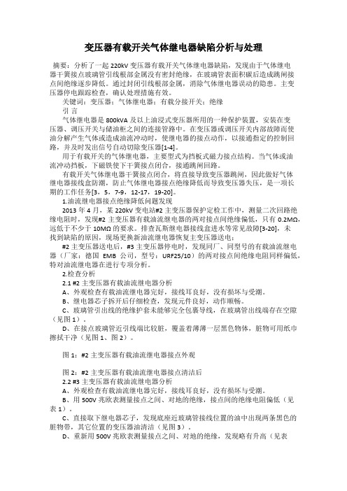
1.油流继电器接点绝缘降低问题发现2013年4月,某220kV变电站#2主变压器保护定检工作中,测量二次回路绝缘电阻时,发现#2主变压器有载油流继电器的两对接点间绝缘偏低,只有0.2MΩ,远低于不少于10MΩ的要求。
排查瓦斯继电器接线盒进水等常见故障[3-20],未找到缺陷的原因,现场更换新油流继电器恢复主变压器送电;#2主变压器送电后,#3主变压器停电时,发现同厂、同型号的有载油流继电器(厂家:德国EMB公司,型号:URF25/10)的两对接点间绝缘电阻同样偏低,特对油流继电器在进行专项分析。
2.检查分析2.1 #2主变压器有载油流继电器分析A、外观检查有载油流继电器完好,接线耳良好,没有损坏与受潮。
B、继电器芯子拆开后仔细检查,发现元件良好,动作顺畅。
C、玻璃管引出线的绝缘护套未能够完全包裹导线,在玻璃管出线端存在空隙(见图1)。

中学校先生対象説明会
第Ⅲ類英文系説明会学校説明会(全類型)8月23日(火)
9月10日(土)
10月15日(土)
15:00~10:00~10:00~本校 第1会議室本校 第1体育館本校 第1体育館中学校の先生
中学生,保護者
中学生,保護者
①第Ⅲ類英文系について①第Ⅲ類英文系について①本校の教育活動について ・英文系の教育課程 ・英文系の教育課程 ・全類型の教育課程
・英文系の特色ある取り組み ・英文系の特色ある取り組み ・学習指導,進路指導について ・適性検査・推薦入学 ・適性検査・推薦入学 ・入試選抜について②第Ⅰ類の特色選抜について②施設見学・生徒発表②施設見学・生徒発表 ・学校の特色と求める生徒像③質問相談コーナー
③質問相談コーナー
・選抜方法等
④クラブ見学(当日練習予定クラブのみ)
平成23年度 京都市立紫野高等学校 スクールガイダンスの内容と申し込み(概要)
内容
対象場所開催日。

DFR ManagerInstruction Manual NR Electric Co.,Ltd.DFR Manager Instruction Manual PrefaceCopyrightVersion:R1.01P/N:EN_HTJK5118.0086.0002Copyright©NR2010.All rights reservedWe reserve all rights to this document and to the information contained herein.Improper use in particular reproduction and dissemination to third parties is strictly forbidden except where expressly authorized.The information in this manual is carefully checked periodically, and necessary corrections will be included in future editions.If nevertheless any errors are detected,suggestions for correction or improvement are greatly appreciated.We reserve the rights to make technical improvements without notice.NR ELECTRIC CO.,LTD.69Suyuan Avenue.Jiangning,Nanjing211102,China Tel:86-25-87178185,Fax:86-25-87178208 Website:Email:international@DFR Manager Instruction ManualDFR Manager Instruction Manual Table of Contents Preface (i)Table of Contents (iii)Chapter1Overview (1)Chapter2User Management (5)Chapter3Configuration Management (9)3.1Region Management (10)3.1.1Add Region (10)3.1.2Delete region (10)3.2Substation Management (11)3.2.1Add Substation (11)3.2.2Delete Substation (11)3.3DFR Management (12)3.3.1Add DFR (12)3.3.2Delete DFR (15)3.3.3Copy DFR (15)3.3.4Paste DFR (15)3.4Add/Delete Component (16)3.4.1Add Voltage Component (16)3.4.2Add Line Current Component (17)3.4.3Add Transformer Branch Current Component (18)3.4.4Delete Component (20)3.5Channel Management&Component Management (20)3.5.1AI Channel Management (20)3.5.2BI Channel Management (24)3.5.3BO Channel Management (26)3.5.4Component Setting Management (26)3.5.5Component Management (27)3.6DFR Configuration and Program Management (27)DFR Manager Instruction Manual3.6.1Program Management (28)3.6.2Configuration Management (29)3.6.3Calibration Setting Management (32)3.6.4Programmable Logic (32)Chapter4Operation Management (35)4.1Overview (35)4.2Management of“Fault Records” (36)4.3Management of“DFR Events” (42)4.4Management of Local Waveform Files (43)4.5Management of Waveform Files in the DFR (43)4.6Monitoring of Real-time Status (45)4.7DFR Remote Operation (46)4.8Other Functions (47)Chapter5Manual Version History (49)Chapter1Overview Chapter1OverviewDFR Manager is a special tool which integrates the configuration and operation management of PCS series Disturbance&Fault Recorder s(DFR s for short),and it can be applied in the control centers or the substations.The main functions of DFR Manager are introduced as below.1)User Management:The adding,deletion and modification of the user information,and theconfiguration of the user short message service(SMS)numbers and E-mail addresses, etc;2)Configuration Management:Configure the boards,components and settings of DFR;theadding,deletion and modification of the region,substation and DFR;3)Operation Management:the management of fault record&IED event,the managementof local waveform files and the waveform files in the DFR,the supervision of DFR status.Figure1-1The main interface of DFR Manager(Operation mode)Chapter1OverviewFigure1-2The main interface of DFR Manager(Configuration mode)The interface is mainly divided into5parts:the menu bar,the toolbar,the DFR tree,configuration window and operation window.Two modes are optional:configuration mode and operation mode.These2modes can be switched by clicking the menu“:Switch between the configuration mode and operation mode.2):Add System,Region,Station,DFR or component.4)Chapter1Overview5):To issue clock synchronization signals to the DFR.7):To send reset commands.The DFR tree list is generated with the hierarchy of System,Region,Station,DFR and component. If a node is deleted,all the nodes belong to it will be deleted,too.(E.g.:When a substation is deleted,all the DFR information in the substation will be deleted,too.)At the same time,when the fault records of the DFR have been received by DFR Manager,DFR Manager can inform the users by SMS and E-mail.Chapter1OverviewChapter2User Management Chapter2User ManagementIn the DFR management system,the users are divided into the system level user and the region level user.The system level user can manage the personnel and devices of the whole system, but the region level user can only manage the personnel and devices of a region of the system.Both the system level user and the region level user are also divided into:the administrator, the maintainer and the operator(i.e.the role of the users).Sometimes the maintainer and the operator are called as the common users.The difference between the administrator and the maintainer is that the administrator can configure of the user information within the controlled area.The difference between the maintainer and the operator is that the maintainer can configure configuration/operation management of the DFR within the controlled area,while the operator can only configure browsing/operation and management of the DFR.Figure2-1User configuration interfaceAdd User:Click the button“”to pop up a prompt to confirm whether to delete the user or not.Chapter2User ManagementNOTE:Each user can not delete himself and can only be deleted by the administrator of higher level.●Set the Password:The password needs to be input twice in the2text areas to the right of“Password”and“Password again”,and the2passwords are required to be the same.The passwords in the interface are invisible.●Set the phone number to receive SMS.Fill in the mobile phone number in the text area to theright of“SMS”:Each bit of a valid mobile phone number must be a digit.SMS function will be enabled only when the corresponding“Enable”is selected.●Set the E-mail address in the text area to the right of“EMAIL”:A valid E-mail address mustinclude the symbol“@”and“.”.E-mail function will be enabled only when the corresponding “Enable”is selected.NOTE:The SMS and the E-mail are filtered according to the region that the DFR belongsto where the alarms(the fault records and the DFR events)occur.The SMS and the E-mail are only sent to the available users who have the privilege to receive SMS/E-mail in this region and this system level.●Set the region in the text area to the right of“Region”:Select the belonging region in thedrop-down box of the region.This region list is maintained in the DFR configuration management interface.NOTE:When a region is deleted in the DFR configuration management interface asshown in the following figure,a prompt will appear in the user configuration interface to indicate that the information of the region where the user belongs to is wrong,and that it is necessary to set the region of this user again.Figure2-2The prompt after deleting the region where the user belongs to●Set the role in the text area to the right of“Role”:Select the role in the correspondingdrop-down box.●Save the user:Click the button“Chapter2User Management appear.NOTE:In the User Configuration interface:1)Each user can not delete himself.Figure2-3Each user can not delete himself2)The administrators(including the area level administrator and the system leveladministrator)can modify the information of all the users controlled by them,but the other users can only modify their own information.Figure2-4User management area of the administrators and other users3)Only the system level administrator can modify the information of the regions where theother users belong to and configure all the users.The other users can only select the region themselves belong to and can not modify the region configuration of other users.Chapter2User ManagementFigure2-5The region configuration options of the system level administrator and other users4)The common users(the maintainer or the operator)can not modify their own roles afterlogging in.Only the administrators(including the area level administrator and the system level administrator)can modify the roles of the users within the controlled area.Figure2-6The role configuration options of the administrator and other usersChapter3Configuration Management Chapter3Configuration ManagementThe configuration management mainly includes:●The configuration of the region,substation and DFR;●The configuration of the analog/digital channels of the voltage component,line currentcomponent and transformer branch current component;the association configuration of these components;●Download the programs of DFR;Upload and download the configuration files of DFR.Uploadthe settings in the menu“CalibrateSetting”of PCS-996R.NOTE:The configuration management function can only be used by the administratorand the maintainer.The operator does not have the authority to configure the DFR,so the configuration menu will not appear for the operator.The region configuration is mainly designed for the manager to manage the DFR s of the controlled substations,but the uncontrolled DFR s and substations will be invisible.The configuration management mainly aims at the DFR management.DFR management consists of2parts:1)Physical device configuration:The parameter configuration of the device itself,i.e.:Name,Type,Sample Rate,IP and Board Type.2)Logic unit configuration:This refers to the component configuration.NOTE:Component is a logic concept that corresponds to primary equipment.Thenames of the components share the name of primary equipment.Component is a logic concept that corresponds to primary equipment.The names of the components share the name of primary equipment.The components can be divided into3types:1)Voltage component:The voltage component mainly refers to the busbar voltage or the line voltage.2)Line current component:3)Transformer branch current component:Because the parameters of line and the parameters of transformer branch are different (The line has positive/zero sequence impedance/admittance,while the transformerChapter3Configuration Managementbranch only has the property about which side of the transformer.i.e.:HV/MV/LV side), so the current component can be divided into2types:line current component and transformer branch current component.In the power system,the voltage sampling mainly refers to the busbar voltages,while each line and transformer has its own current sampling channel,thus some current components correspond to a voltage component,i.e.:some current components relate to1voltage.The component configuration mainly aims at setting the relationships between the components and the physical channels.Similar to the protection relays,DFR also has a criterion to trigger waveform and some functional units for protection,so DFR also has some settings.The functional units for protection correspond to the components.NOTE:Generally speaking,the number and type of the analog channels relate to thetype of the functional units for protection.E.g.:If a functional unit for protection needs to sample zero-sequence current,so it is forbidden to assign only1phase current(such as Ia)to the corresponding component,because zero-sequence current can not be acquired by sampling only1phase current.3.1Region Management3.1.1Add RegionSelect the“System”node,and then right-click and select the“Add Region”menu to pop up a dialog as shown in the following figure.Input the region name and click“OK”to add a region.Figure3.1-1Add regionNOTE:The region name should not include any spaces.Please use“_”to separate2words instead of a space.3.1.2Delete regionSelect the region node to be deleted,right-click the menu and select“Delete Region”to pop up a dialog as shown in the following figure to confirm whether to delete it or not.You can delete this region(including all the information of the substation and the DFR in this region)after confirmation.Chapter3Configuration ManagementFigure3.1-2Delete regionNOTE:1)Only the system administrator and the maintainer can add/delete a region.2)In order to avoid deleting all the substations and the devices in the region when deleting theregion wrongly,the system will not allow deleting a region when it still have substations in it,i.e.:it is necessary to delete all the substations in this region firstly.3.2Substation Management3.2.1Add SubstationSelect the region node to add substation,select the menu“Add Station”to pop up a dialog as shown in the following figure.Input the substation name and then click“OK”to add a substation. The address of the substation will be assigned automatically.Figure3.2-1How to add stationFigure3.2-2Add substation3.2.2Delete SubstationSelect the substation node to be deleted.Select the right-click menu“Delete Station”to pop up a dialog as shown in the following figure to delete this substation(including all the information of the DFR in this substation)after confirmation.Chapter3Configuration ManagementFigure3.2-3Delete substationNOTE:The software allows deleting the whole substation.However,ensure that it is necessary to delete the whole substation and all the DFR information in it before deleting.3.3DFR Management3.3.1Add DFRSelect the substation to add DFR,select the right-click menu“Add DFR”to pop up a dialog as shown in the following figure to add a DFR.Figure3.3-1Add DFRThe following parameters can be configured in this dialog:1)Name:The name of the DFR;2)Type:The specific type of the DFR;3)Sample Rate:4800or9600(bps)can be selected as the sampling rate;4)IP:The IP address of the DFR;5)NetMask:The subnet mask of the DFR;6)Gateway:The gateway address of the DFR.After clicking the“OK”button in the above figure,the board type of each slot and the analog channels,binary channels,GOOSE channels will be generated automatically according to theChapter3Configuration Managementdefault configuration.But the components will not the generated automatically,so there is no association between the channels and components when a DFR is generated.Figure3.3-2Properties of the DFRThe board configuration can be modified in the“Hardware Config”page later.The number of the analog channels,binary channels,GOOSE channels will be influenced after modifying the board configuration.The2nd column in the“Hardware Config”page is the“Board Type”.The3rd column in the“Hardware Config”page is the“Board Desc”to indicate whether it is a CPU board or a DSP board,etc.Where:AI:Analog input.AI-12U indicates12voltage inputs.AI-6I indicates6current inputs.BI:Binary input.BO:Binary output.GS:GOOSE binary input.AI boards can be configured in the4th~11th slot.BI boards can be configured in the10th~14th slot.The“Voltage Level”is only applied for the BI boards.24V,48V,110V,220V are optional.NOTE:Both the AI boards and BI boards can be configured in the10th~11th slot.Chapter3Configuration ManagementFigure3.3-3The“Hardware Config”pageThe board which occupies2slots must start from the slot of an even number.E.g.:As shown in the above figure,NR1401-12U can only occupy the4th~5th,the6th~7th,the 8th~9th or the10th~11th slot.NOTE:If a board which only occupies1slot needs to be replaced by a board whichoccupies2slots,the2slots must be set as“Slot Not Installed”first,i.e.:the former boards in the2slots must be taken out so as to insert the new board which occupies2 slots.Figure3.3-4The configuration of the board which occupies2slots3.3.2Delete DFRSelect the DFR node to be deleted.Click the right-click menu“Delete DFR”to pop up a dialog box as shown in the following figure to delete this DFR(including all the information in this DFR).Figure3.3-5Delete DFR3.3.3Copy DFRSelect the DFR node to be copied,click the right-click menu“Copy DFR”to copy the DFR (including all the information in it except the name and IP).Figure3.3-6Copy DFR3.3.4Paste DFRIf a DFR has been copied,select the substation node to paste this DFR,and then click the right-click menu“Paste DFR”to paste it.Except the IP address,all the other parameters are the same as the parameters of the copied DFR.For similar Disturbance&Fault Recorders,the DFR configuration can be accomplished conveniently by using“Copy DFR”and“Paste DFR”.Figure3.3-7Paste DFR3.4Add/Delete Component3.4.1Add Voltage ComponentSelect the DFR node to add voltage component and click the right-click menu“Add Component”to pop up a dialog as shown in the following figure.Figure3.4-1Add voltage componentIn this dialog,select“Voltage”and then click“OK”to pop up a new dialog to set the parameters of the voltage component as shown in the following figure.Figure3.4-2The dialog to set the parameters of voltage component1)Name:The name of the voltage component;2)U1n(kV):The rated primary voltage.Unit:kV.3)U2n(V):The rated secondary voltage.Unit:V.4)Voltage Type:“Bus Voltage”and“Line Voltage”are optional.5)Channel Type:4options are provided:“Uabc0”:Three phase voltages and zero sequence voltage are selected.“Uabc”:Three phase voltages are selected.“Upp”:Only the voltages of2phases are selected.“Up”:Only the voltage of1phase is selected.NOTE:The parameters of voltage components will remain the same when a new voltageis added.When DFR Manager is closed and opened again,the parameters of voltage components can still remain the same.It is the same for the parameters of line current components and transformer branch current components.3.4.2Add Line Current ComponentSimilar to adding the voltage component,select“Line current”in the dialog in Figure3.4-1,click “OK”to pop up a new dialog as shown in the following figure,input the parameters and then click “OK”to add a line current component in the DFR.Figure3.4-3The dialog to set the parameters of line current component1)Name:The name of the line current component;2)I1n(A):The rated primary current.Unit:A.3)I2n(A):The rated secondary current.Unit:A.4)R1(ohm):The primary positive sequence resistance.Unit:ohm.5)R0(ohm):The primary zero sequence resistance.Unit:ohm.6)X1(ohm):The primary positive sequence reactance.Unit:ohm.7)X0(ohm):The primary zero sequence reactance.Unit:ohm.8)C1(μF):The primary positive sequence capacitance.Unit:μF.9)Length(km):The length of the line.Unit:km;10)Channel Type:4options are provided:“Iabc0”:Three phase currents and zero sequence current are selected.“Iabc”:Three phase currents are selected.“Ipp”:Only the currents of2phases are selected.“Ip”:Only the current of1phase is selected.3.4.3Add Transformer Branch Current ComponentSelect“Transformer branch current”in the dialog box in Figure3.4-1.Click“OK”to pop up a new dialog as shown in the following figure.Input the parameters and then click“OK”to add a transformer branch current component node in the DFR.Figure3.4-4The dialog to set the parameters of transformer branch current componentThe parameters in the above dialog are introduced as below:1)Name:The name of the transformer component;2)I1n(A):The rated primary current.Unit:A.3)I2n(A):The rated secondary current.Unit:A.4)Branch Type:3options are provided:“High voltage side”:The HV side branch of the transformer is selected.“Middle voltage side”:The MV side branch of the transformer is selected.“Low voltage side”:The LV side branch of the transformer is selected.5)Channel Type:4options are provided:“Iabc0”:Three phase currents and zero sequence current are selected.“Iabc”:Three phase currents are selected.“Ipp”:Only the currents of2phases are selected.“Ip”:Only the current of1phase is selected.NOTE:The difference between the current of transformer branch component and theline current component is that the former has no component parameters and settings related to the line.3.4.4Delete ComponentSelect a voltage component,a line current component or a transformer branch current and click the right-click menu“Delete Component”to delete a component.3.5Channel Management&Component Management3.5.1AI Channel ManagementWhen a component is added,the functional unit for protection will be generated automatically,at the same time,the analog channels with a certain number,order and type will be occupied according to the“Channel Type”of the component.E.g.:If a voltage component is added first and the“Channel Type”of the component is“Uabc0”, the first4voltage channels of the1st analog board with voltage channels will be occupied by this component automatically.I.e.:the physical analog channels and the logical components are associated.Figure3.5-1AI channel configurationGenerally speaking,the channels occupied by a component are arranged continuously,so the component names will be merged to make it easy to view them.Sometimes,the channels occupied by which component and the channel type need to be modified by the user.Right click the table and click the pop-up menu“Figure3.5-3The channel type Volt.and corresponding Component sFigure3.5-4The channel type Volt.and corresponding Type sFigure3.5-5The channel type Curr.and corresponding Component sFigure3.5-6The channel type Curr.and corresponding Type sThe properties of the A I channel are introduced as below:1)Board:The information of the board that this channel belongs to.;2)Channel No.:The channel number.3)PIN Type:The type of this channel:Volt.(voltage)or Curr.(current).4)Component:The component name.5)Type:The type of this channel:Ua,Ub,Uc,3U0,Ia,Ib,Ic,3I0…..6)Description:The description of this channel and this property is editable.When a component is selected,a dialog as shown in the following figure will pop up to prompt whether to set the next several channels continuously.If“OK”is selected,the next several channels with the same type will be set according to the“Channel Type”of this component.If “Cancel”is selected,each channel will be set separately.Figure3.5-7The dialog to set the next several channels continuouslyHere is an example to explain this function.If the“Component”name of a current channel is“Line01”,and the corresponding“Channel Type”of“Line01”is“Iabc0”,if“OK”is selected in the above figure,the“Type”column of the following3current channels will be set as“Ib”,”Ic”,”3I0”automatically,and the“Component”column of the following3current channels will be set as“Line01”automatically.Figure3.5-8The interface before selecting“OK”in the above figureFigure3.5-9The channels after selecting“OK”If“Cancel”is selected in the above figure,the number and type of the channels may be inconsistent with the“Channel Type”of the component,e.g.:only a channel“Ic”is assigned to a component with a“Channel Type”of“Iabc”.To deal with this problem,a self-check function is provided to ensure the consistency of the component type and the channel:Select a DFR and then right-click it,click the submenu“Check Component and Channel…”or the menu“Figure3.5-11The configuration of the BI channelsFigure3.5-12Associate the Component and the BI channelFigure3.5-13The“Relay Operation”of the BI channelFigure3.5-14The“Trigger Type”of the BI channel3.5.3BO Channel ManagementFigure3.5-15The configuration of the BO channels3.5.4Component Setting ManagementThe values of settings can be configured here,and the settings can be enabled/disabled here.Figure3.5-16The settings of the analog quantities3.5.5Component ManagementThe name of components and the association relationship between the current component(i.e.: the“Line current”and“Transformer branch current”components)and the voltage component can be configured here.Figure3.5-17The configuration of the component name and the association relationshipNOTE:During adding a region/station/device or modifying the name or IP address of aDFR(i.e.:the operation that can influence the running of DFR),the button“”to publish the modification in the logic database to physical database.The publishing process will take some time.3.6DFR Configuration and Program ManagementThe configuration files of DFR are important to the operation of DFR.The tool provides the functions to download the configuration files to DFR and get the configuration files from DFR and save them to database.Meanwhile,the program files of DFR can influence the upgrade of the software version of DFR. The system also provides the remote downloading function for DFR.The management of configurations and programs are realized by selecting a DFR from the tree and right-click the related functions.Figure3.6-1The menu of DFR configuration and program management3.6.1Program ManagementIn the above figure,click the menu“Download Program…”to pop up a dialog as shown in the following figure.Figure3.6-2Download program to DFRClick the button“OK”to pop up the dialog to select the program to download as shown in the following figure.Figure3.6-3Select the program to download to the DFRAs shown in the above figure,select the proper program file to download it to the DFR.3.6.2Configuration ManagementThe Configuration Management include:download configuration,upload configuration,import configuration,export configuration.1)Download configurationSelect the menu“Configuration Download…”to pop up a dialog as shown in the following figure.Figure3.6-4Download configuration to DFRConfirm that the“DFR IP Address”is correct and then click“OK”to start downloading.A progressing bar as shown in the following figure will pop up.Figure3.6-5The progressing bar of configuration downloadingWhen the progressing bar disappears,it indicates that the configuration has been downloaded to the DFR device successfully.Please reboot the DFR device to enable the new configuration.NOTE:During the rebooting of the DFR device,the communication status will bedisconnected for a short time and then will be OK again,and the events about the communication status can be sent to DFR Manager.2)Upload configurationSelect the menu“Configuration Retrieve…”,DFR manager will acquire configuration from the selected DFR device,and a previewing dialog similar to the configuration dialog will appear.This dialog is not editable.Click the button“Import”to import the configuration into DFR manager.NOTE:If the DFR already exists in DFR Manager,DFR Manager will check whether theDFR device is the selected DFR in DFR Manager.If the DFR device is not the selected DFR in DFR Manager,a new dialog will pop up to prompt whether to create a new DFR in DFR Manager or to import the configuration into the selected DFR in DFR Manager.If the DFR does not exist in DFR Manager,the region name,station name and device name of the DFR will be created in DFR Manager,thus the new DFR will be created in DFR manager and then the corresponding configuration will be imported.The region name,station name and device name will be filled by the configuration downloaded from the DFR.If the region name,station name and device name have been modified before importing,DFR Manager will search corresponding DFR device and then import the configuration from this DFR device.NOTE:The configuration of the boards,channels,components will be deleted when theconfiguration is imported into DFR Manager.Figure3.6-6The previewing interface for uploading configuration3)Export configurationSelect the menu“Configuration Export…”to export the configuration of a DFR as an.xml file. Detail configuration information is stored in this file.4)Import configurationSelect a DFR and right-click on it to pop up a menu,select the submenu“Configuration Import…”to import the configuration stored in the.xml file into the selected DFR.NOTE:The configuration of the boards,channels,components will be deleted wheneither of the2methods is applied.Generally speaking,2methods are provided to import configuration:1)Upload configuration from a DFR and import the configuration to a DFR in DFRManager.In this method,if the DFR does not exist in DFR Manager,the DFR will be created in DFR Manager.2)Import configuration from an.xml file into the selected DFR in DFR Manager.In this method,if the DFR does not exist in DFR Manager,no DFR will be created in DFR Manager.。
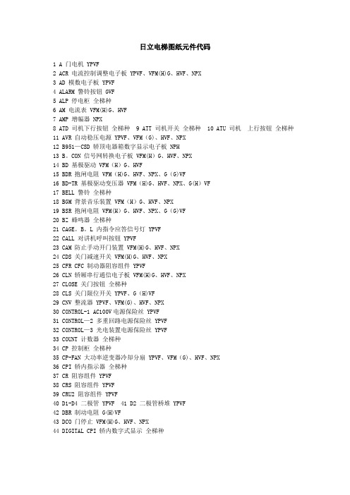
日立电梯图纸元件代码1 A 门电机 YPVF2 ACR 电流控制调整电子板 YPVF、VFM(H)G、HVF、NPX3 AD 模数电子板 YPVF4 ALARM 警铃按钮 GVF5 ALP 停电柜全梯种6 AM 电流表 VFM(H)G、HVF7 AMP 增幅器 NPX8 ATD 司机下行按钮全梯种9 ATT 司机开关全梯种10 ATU 司机上行按钮全梯种11 AVR 自动稳压电源 YPVF、VFM(G)、HVF、NPX12 B951—CSD 轿顶电器箱数字显示电子板 NPH13 B。
CON 信号网转换电子板 VFM(H)G、HVF、NPX14 BD 基极驱动 VFM(H)G、HVF15 BDR 抱闸电阻 VFM(H)G、HVF、NPX、G(G)VF16 BD-TR 基极驱动变压器 VFM(H)G、HVF、NPX、G(H)VF17 BELL 警铃全梯种18 BGM 背景音乐装置 VFM(H)G、HVF、NPX19 BSR 抱闸电阻 VFM(H)G、HVF、NPX、G(G)VF20 BZ 蜂鸣器全梯种21 CAGE。
B。
L 内指令应答信号灯 YPVF22 CALL 对讲机呼叫按钮 YPVF23 CAM 防止手动开门装置 VFM(H)G、HVF、NPX24 CDS 关门减速开关 VFM(H)G、HVF、NPX25 CFR CFC 制动器阻容组件 YPVF26 CLN 轿厢串行通信电子板 VFM(H)G、HVF、NPX27 CLOSE 关门按钮全梯种28 CLS 关门限位开关 YPVF、G(H)VF29 CNV 整流器 YPVF、VFM(G)、HVF、NPX30 CONTROL-1 AC100V电源保险丝 YPVF31 CONTROL—2 多重回路电源保险丝 YPVF32 CONTROL—3 光电装置电源保险丝 YPVF33 COUNT 计数器全梯种34 CP 控制柜全梯种35 CP-FAN 大功率逆变器冷却分扇 YPVF、VFM(G)、HVF、NPX36 CPI 轿内指示器全梯种37 CR 阻容组件 YPVF38 CRS 阻容组件 YPVF39 CRU2 阻容组件 YPVF40 D1-D4 二极管 YPVF 41 D2 二极管桥堆 YPVF42 DBR 制动电阻 G(H)VF43 DCO 门停止 VFM(H)G、HVF、NPX44 DIGITAL CPI 轿内数字式显示全梯种45 DLS 下终端限位开关全梯种46 DM1 电感线圈 YPVF47 DM37 副安全触板短接开关 G(H)VF48 DM 门电机 G(H)VF49 M。

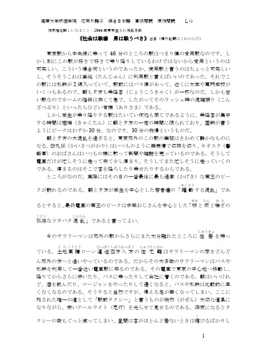
作家椎名誠しいなまこと:1944年東京生まれ作品多数《社会は戦場 男は戦うべき》出自《場外乱闘はこれからだ》東京駅から中央線に乗って46分のところの駅はつまり僕の愛用駅なのです。
しかし別にこの駅が好きで好きで乗り降りしているわけではないから愛用というのは可笑しい。
こういう場合何というのであったか、使用駅と言うのはちょっと可笑しいし、そうそうこれは単純(たんじゅん)に利用駅と言えばいいのであった。
それでこの駅には私鉄が2線入っていて、駅前にはバス停があって、近くに大学や専門学校がいくつもあるので、朝も夕方も乗降客(じょうこうきゃく)が一杯なのだ。
しかも古い駅なのでホームの階段は狭くて急で、したがってそのラッシュ時の混雑振り(こんざつぶり)といったらひどい有様(ありさま)である。
しかし学生が乗り降りする駅はたいてい何処も同じであるように、乗降客が集中する時間は極端(きゃくたん)に朝と夕方の一定の時間に限られており、国鉄が言うようにピークはわずか30分、なのです。
30分の我慢というものだ。
朝と夕方の大混乱を過ぎると、東京郊外のこの駅の業務はきわめて静かなものになる。
改札係(かいさつがかり)はいつものように無表情で切符を切り、キオスク(書報亭)のおばさんはいつもの様に黙って新聞や雑誌を売っているのである。
そうして電車だけが忙しそうに走って来て少し停まり、そうしてまた忙しそうに走っていくのである。
停まるのはそこで客を降ろしたり乗せたりするからである。
ところがなのだ。
実際にはその日の一番最後に最も過激(かげき)な第三のピークが訪れるのである。
朝と夕方が学生を中心とした若者達の「躍動やくどうする混乱」であるとすると、最終電車の第三のピークは中年おじさんを中心とした「咳せきと痰たんと喘ぎあえの孤独こどくなドタバタ混乱こんらん」であると言ってよい。
今のサラリーマンは郊外の駅からさらにまた大分離れたところに住居じゅうきょを持っている。

IOD-40249/2016OPERATION MANUALMODELSAir Handling UnitFXTQ09TAVJUA FXTQ09TAVJUD FXTQ12TAVJUA FXTQ12TAVJUD FXTQ18TAVJUA FXTQ18TAVJUD FXTQ24TAVJUA FXTQ24TAVJUD FXTQ30TAVJUA FXTQ30TAVJUD FXTQ36TAVJUA FXTQ36TAVJUD FXTQ42TAVJUA FXTQ42TAVJUD FXTQ48TAVJUA FXTQ48TAVJUD FXTQ54TAVJUA FXTQ54TAVJUD FXTQ60TAVJUAFXTQ60TAVJUDSYSTEM Inverter Air ConditionersRead these instructions carefully before installation. Keep this manual in a handy place for future reference. This manual should be left with the equipment owner.Lire soigneusement ces instructions avant l’installation.Conserver ce manuel à portée de main pour référence ultérieure. Ce manuel doit être donnéau propriétaire de l’équipement.Lea cuidadosamente estas instrucciones antes de instalar.Guarde este manual en un lugar a mano para leer en caso de tener alguna duda. Este manual debe permanecer con el propietario del equipo.•Do not allow children to play on or around the unit to prevent injury.•The heat exchanger fins are sharp enough to cut. To avoid injury, wear gloves or cover the fins while work-ing around them.•Do not put a finger or other objects into the air inlet or air outlet. The fan is rotating at high speed and will cause injury.•Check the unit foundation for damage on a continu-ous basis, especially if it has been in use for a long time. If left in a damaged condition the unit may cause injury.•Placing a flower vase or other containers with water or other liquids on the unit could cause a shock or fire if a spill occurs.•Never touch the internal parts of the controller. Do not remove the front panel because some parts in-side are dangerous to touch. To check and adjustinternal parts, contact your dealer.•Do not use the heat pump for any other purposes other than comfort cooling or heating. Do not use the unit for cooling precision instruments, food, plants, animals or works of art.•Do not place items under the indoor unit as they may be damaged by condensates that may form if the humidity is above 80% or if the drain outlet gets blocked.•Before cleaning, stop the operation of the unit by turning the power off or by pulling the supply cord out from its receptacle. Otherwise, an electric shock and injury may result.•Do not wash the heat pump with excessive water. An electric shock or fire may result.•Avoid placing the controller in a spot splashed with water. Water entering the controller may cause an electric shock or damage the internal electronic parts.•Do not operate the heat pump when using a room fumigation type of insecticide. Failure to observe this could cause the chemicals to be deposited in the unit and can endanger the health of those who are hyper-sensitive to chemicals.•The appliance is not intended for use by young chil-dren or infirm persons without supervision.•The remote controller should be kept away from chil-dren so they cannot play with it.•Consult with the installation contractor for cleaning.•Incorrect cleaning of the inside of the heat pump could make the plastic parts break and cause water leakage or electric shock.•Do not touch the air inlet or aluminum fin of the heat pump as they can cut and cause injury.•Do not place objects in direct proximity of the out-side unit. Do not let leaves and other debris accumu-late around the unit. Leaves are a hotbed for small animals which can enter the unit. Once inside the unit, animals can cause the unit to malfunction and cause smoke or fire when they make contact withelectrical parts.•Never press the button of the remote controller with a hard, pointed object. The remote controller may be damaged.•Never pull or twist the electric wire of the remote con-troller. It may cause the unit to malfunction.•Do not place appliances that produce open flames in places that are exposed to the air flow of the unit or under the indoor unit. It may cause incomplete com-bustion or deformation of the unit due to the heat.•Do not expose the controller to direct sunlight. The LCD display can become discolored and may fail to display the data.•Do not wipe the controller operation panel with ben-zene, thinner, chemical dust cloth, etc. The panel may get discolored or the coating can peel off. If it is heavily dirty, soak a cloth in water-diluted neutral detergent, squeeze it well and wipe the panel clean.Then wipe it with another dry cloth.•Dismantling of the unit, disposal of the refrigerant, oil, and additional parts, should be done in accor-dance with the relevant local, state, and national regu-lations.•Operate the heat pump in a sufficiently ventilated area and not surrounded by obstacles. Do not use the heat pump in the following places.a.Places with a mist of mineral oil, such as cuttingoil.b.Locations such as coastal areas where there is alot of salt in the air.c.Locations such as hot springs where there is a lotof sulfur in the air.d.Locations such as factories where the power volt-age varies a lot.e.In cars, boats, and other vehicles.f.Locations such as kitchens where oil may splat-ter or where there is steam in the air.g.Locations where equipment produces electromag-netic waves.h.Places with an acid or alkaline mist.i.Places where fallen leaves can accumulate orwhere weeds can grow.•Do not attempt to do electrical work or grounding work, unless you are licensed to do so. Consult with your dealer for electrical work and grounding work.•Pay attention to operating sound. Be sure to use the following places:a.Places that can sufficiently withstand the weightof the heat pump yet can suppress the operat-ing sound and vibration of the heat pump.b.Places where warm air from the air outlet of theoutside unit or the operating sound of the out-side unit does not annoy neighbors.•Consult your dealer if the heat pump in operation gen-erates unusual noise.•Make sure that the drainpipe is installed properly to drain water. If no water is discharged from the drain-pipe while the heat pump is in the cooling mode, the drainpipe may be clogged with dust or dirt and water leakage from the indoor unit may occur. Stop oper-ating the heat pump and contact your dealer.2.3.MAINTENANCE•Only a qualified person is allowed to perform mainte-nance without daily maintenance.•Before touching any of the connection wirings, be sure to turn off all power supply switches.•For installation of optional parts, only a qualifited person is allowed to do so.Be sure to use optional parts specified by the manufac-turer. Installation in your own manner may result in wa-ter leakage, electric shock or fire.•Do not use flammable material (e.g. hair-spray or insec-ticide) near the product.•Only proceed with the unit cleaning after stopping the operation and turning the power supply off.Failure to do so may result in electric shocks or injury.•Do not wash the heat pump or air handler with water.Failure to do so may result in an electric shock.•Consult with installation contractor for cleaning the inside of the air handler.Wrong cleaning procedures may break plastic parts or cause water leakage or electric shock.•Use a stable prep stand.Pay extra attention when cleaning the air handler. (Maintenance and inspection)•Clean the drain pan periodically. The drain pipes clogged with dust will cause water leakage.•For cleaning, consult with your Daikin dealer. (Before each season when cooling or heating is required, clean the air handler.)•If the area around the indoor unit is very dusty, use a dust proof cover (local procurement).(Cleaning the inside of the indoor unit)•It is necessary to clean the inside of the indoor unit peri-odically.Since the cleaning requires special technologies, requesta Daikin dealer to clean them.(Electric heater replacement interval)•The electric heater should be replaced every ten years.This replacement interval is a guideline for ensuring safe and trouble-free operation of the product for many years. (Cleaning the air filter)•The air filter is an optional accessory.EXPLANATION:•Removing the air filter except when cleaning the air han-dler may result in accidents.•Replace the filter when one of the following messages displayed on the bottom of remote controller screen.- Time to clean filter & element- Time to clean filter•If using the air handler under very dusty environment, increase the frequency of air filter cleaning.•Reset the filter sign on main menu of remote controller.Refer an operation manual of remote controller for de-tail.•Consult dealer to change filter setting time to display fil-ter change alarm on remote controller screen. (The de-fault factory setting is 2500 hours.)•There are the following time, display pattern: 1250, 2500, 5000, 10000.•Do not allow the indoor unit to get wet as it may cause an electric shock or fire._______________________________________________ 4. PRECAUTIONSIf the following phenomenon occurs, contact your dealer.•Any abnormalities in the operation of the heat pump or air handler such as smoke or fire could result in severe injury or death.Turn off the power and contact your dealer immediately for instructions._______________________________________________ Phenomenon•The unit may operate with the airflow rate at high speed even though the airflow rate was set to low speed using the remote controller during ELECTRIC HEATER opera-tion.Take the following actions before contact.Check to see if an optional electric heater is installed.The unit operates with the airflow rate at high speed dur-ing ELECTRIC HEATER operation regardless of the re-mote controller airflow rate setting or display.Phenomenon•The safety devices such as fuse, breaker, ground fault interrupter, etc. often operate or operations of the opera-tion switch are unstable.Take the following actions before contact.Turn off the switch.•If the ON/OFF switch does not properly work, Take the following actions before contact.Turn off the main power switch.Phenomenon•Water leaks out from the air handle r.Take the following actions before contact.Stop the operation.Phenomenon•Error message is displayed. See the remote controller operation manual for details.Inform the dealer of the details being displayed on the remote controller.。