NCM45X0-2 network control module
- 格式:pdf
- 大小:67.27 KB
- 文档页数:2
usb ncm报文格式解析-回复USB NCM(Network Control Model)是一种用于在USB设备之间进行网络通信的协议,它通过USB接口传输数据,使设备能够在没有网络接口的情况下进行网络通信。
本文将详细解析USB NCM报文的格式,包括报文头、数据传输包等内容,以帮助读者更好地理解和应用该协议。
首先,我们需要了解USB NCM报文的基本结构。
USB NCM报文由报文头和数据传输包组成,其中报文头包含了一些必要的字段信息,数据传输包则用于携带具体的数据。
报文头的结构如下所示:1. Signature:一个4字节的字段,用于标识报文的开始部分,固定值为"NCMZ"。
2. Message Type:一个2字节的字段,用于指示报文的类型,包括Command、Data和Response。
3. Message Length:一个4字节的字段,用于表示报文的长度,包括报文头和数据传输包的长度。
4. Reserved:一个2字节的保留字段,目前仅用于填充。
5. CRC32:一个4字节的字段,用于校验报文的准确性,计算方法为对整个报文进行CRC32校验。
接下来是数据传输包的结构。
数据传输包用于携带具体的数据内容,它的格式可以根据应用的需要而变化。
在数据传输包中,通常包含以下几个字段:1. Data Length:一个2字节的字段,用于表示数据的长度,即下面Data 字段的长度。
2. Reserved:一个2字节的保留字段,目前仅用于填充。
3. Data:一个变长的字段,用于存储具体的数据内容。
除了上述字段外,USB NCM报文还可以包含一些可选的字段,如Vendor-Specific字段,用于存储厂商自定义的数据,以满足特定应用需求。
当我们了解了USB NCM报文的格式后,接下来就可以对报文进行解析和处理了。
首先,我们需要读取报文头中的Signature字段,以验证报文的有效性。

维宏®数控系统NCSTUDIO V5.4软件使用手册目录升级纪录............................................................................................................................ I I 目录.. (I)1概述 (1)1.1软件特性 (1)2系统安装与连接 (3)2.1N CSTUDIO™的系统基本配置 (3)操作系统 (3)2.2N CSTUDIO™系统的安装 (4)安装Ncstudio™软件 (5)安装Ncstudio™运动控制卡 (8)重新启动计算机 (8)2.3其他安装问题 (8)2.4卸载N CSTUDIO™系统 (9)2.5N CSTUDIO™控制卡与驱动系统的连接 (10)3NCSTUDIO™基本概念 (11)3.1操作模式与状态 (11)操作模式 (11)操作状态 (12)3.2机床坐标系 (13)机械坐标系 (13)工件坐标系 (13)4NCSTUDIO™操作界面 (15)4.1标题栏 (16)4.2菜单栏 (17)4.3工具栏 (18)4.4数控信息栏 (19)4.5状态栏 (19)4.6数控状态窗口 (19)加工状态和时间信息 (20)进给速度 (21)机床控制 (22)4.7自动操作窗口 (23)4.8手动操作窗口 (25)4.9加工轨迹窗口 (28)三维视图模式 (28)上下文菜单 (31)设置个性化参数 (31)4.10系统日志窗口 (32)4.11程序管理窗口 (33)4.12系统参数窗口 (34)加工参数 (35)厂商参数 (38)4.13程序编辑窗口 (41)4.14输入输出状态(I/O状态)窗口 (42)5NCSTUDIO™菜单系统 (44)5.1“文件”菜单 (44)打开并装载 (44)卸载 (45)新建加工程序 (46)打开并编辑 (46)编辑当前加工程序 (46)保存 (46)另存为 (46)保存并装载 (47)关闭 (47)最近装载的加工程序 (47)最近编辑的加工程序 (47)退出 (47)5.2“编辑”菜单 (48)5.3“查看”菜单 (49)工具栏 (50)状态栏 (50)全屏 (50)显示加工程序行号 (51)跟踪加工程序当前行 (51)加工程序信息 (52)5.4“操作”菜单 (52)单步执行 (53)设置当前点为工件原点 (53)设置当前点工件坐标 (54)回工件原点 (54)开始 (55)暂停 (56)停止 (56)进入仿真模式并开始仿真 (56)高级开始 (57)断点继续 (57)执行加工指令 (58)微调 (61)对刀 (62)回机械原点 (62)复位 (63)限位释放 (64)5.5“机床”菜单 (64)5.7“帮助”菜单 (65)6操作步骤 (66)6.1开机 (66)6.2机械复位(可选) (66)6.3载入加工程序 (66)6.4手动操作 (67)6.5确定工件原点 (67)6.6执行自动加工 (68)6.7直接定位功能 (69)7操作时的注意事项 (70)7.1多任务执行注意事项 (70)7.2回机械原点注意事项 (70)8最终用户软件许可协议....................................................... 错误!未定义书签。
遥控赛车毕业设计【篇一:遥控赛车毕业论文完整版】目录1 引言 (2)1.1红外遥控技术背景 (2)2 总体设计方案 (4)2.1 方案:红外遥控控制小车 (4)3 necupd6121g红外遥控系统 (5)3.1 necupd6121g (5)3.2 简单发射电路 (5)3.3 发射编码及信号波形 (6)4 at89s52单片机 (11)4.1 at89s52单片机 (11)5 l298n驱动模块 (16)5.11 l298n驱动模块说明 (16)5.2 l298芯片驱动参数 (16)5.3 功能简图 (16)6 遥控赛车系统框图及电路设计 (19)6.1系统框图及电路设计 (19)7红外遥控赛车程序设计 (20)7.1红外信号解码设计框图 (20)7.2 红外接收软件设计 (22)结束语 (24)参考文献 (25)附录一:电路原理图 (26)附录二:赛车实物图 (27)附录三:程序清单 (28)红外遥控赛车软件算法设计陈辉摘要:通过对设计要求的认真分析和研究,拿出了几种可行方案,最终选定一个最佳方案。
该方案是采用先进的单片机技术实现遥控,采用模块化设计,主要分为两个模块:红外遥控模块和l298电机驱动模块。
红外发射模块中通过upd6121g红外遥控器发射管对单片机发射信号,红外接收模块中的单片机受红外接收管接收的信号控制。
文章详细的讨论了实现上述红外遥控过程其工作原理和软件设计。
关键词:遥控器红外发射红外接收单片机1 引言1.1红外遥控技术背景红外遥控是一种无线、非接触控制技术,具有抗干扰能力强,信息传输可靠,功耗低,成本低,易实现等显著优点,被诸多电子设备特别是家用电器广泛采用,并越来越多的应用到计算机系统中。
60年代初,一些发达国家开始研究民用产品的遥控技术,单由于受当时技术条件限制,遥控技术发展很缓慢,70年代末,随着大规模集成电路和计算机技术的发展,遥控技术得到快速发展。
在遥控方式上大体经理了从有线到无限的超声波,从振动子到红外线,再到使用总线的微机红外遥控这样几个阶段。

NC 版本: 340 49x-04 PLC 版本:Basic 54 HEIDENHAIN简明调试手册iTNC 530目录1,调试准备 (1)1.1本手册中标识的含义 (1)1.2 各模块概述 ...................................................................................................... 2 1.2.1 主计算机,硬盘, SIK .......................................................................................... 2 1.2.2 CC 控制单元 ........................................................................................................... 3 1.2.3UV106 B电源模块 ................................................................................................. 4 1.2.4 显示单元和键盘 . .................................................................................................... 5 1.2.5手轮 . ......................................................................................................................... 7 1.2.6 PLC 模块 ................................................................................................................ 8 1.2.7驱动模块 . .. (9)2, 系统连接 ........................................................................................... 10 2.1 一般信息 ........................................................................................................ 10 2.1.1 安全措施 . .............................................................................................................. 10 2.2硬盘(HDR 和 SIK 的安装 . ....................................................................... 11 2.3使用环境 ......................................................................................................... 13 2.3.1温度和湿度 . ........................................................................................................... 13 2.3.2空调 . ....................................................................................................................... 13 2.3.3机械振动 . ............................................................................................................... 14 2.3.4污染 . ....................................................................................................................... 14 2.3 安装空间 ........................................................................................................ 15 2.3.1一般信息 . ............................................................................................................... 15 2.3.2 MC 42x(C, CC42x(B, UV, UM, UE2xxB 安装空间 ......................................... 16 2.3.3显示器 . ................................................................................................................... 16 2.3电气设计重要事项 ......................................................................................... 17 2.3.1供电 . ....................................................................................................................... 17 2.3.2电气柜设计基本要求 . ........................................................................................... 17 2.3.3接地 . ....................................................................................................................... 17 2.4 电缆连接总图 ................................................................................................ 18 2.5 iTNC530连接概览 ..................................................................................... 23 2.6 供电 .............................................................................................................. 26 2.6.1 iTNC 530供电 . ................................................................................................... 26 2.6.2 系统内置 PLC 供电 ........................................................................................... 27 2.6.3 PLC 51x 扩展模块供电 ..................................................................................... 28 2.6.4 Control-Is-Ready 信号供电 . ............................................................................... 28 2.6.5 显示单元(BF 150供电 .. (28)i2.8 手轮 (29)2.8.1 HR 4xx便携式手轮 (30)2.9 PLC 输入信号 (31)3.9.1 输入信号和地址 . .................................................................................................. 31 2.9.2 MC 42x(C内置 PLC 输入信号 ......................................................................... 32 2.9.3 扩展模块 PL 510的输入点 ................................................................................. 33 2.10 PLC 输出信号 ........................................................................................... 34 2.11 PLC输入输出模块 ...................................................................................... 37 2.11.1 PLB511/PLB512 ................................................................................................. 38 2.12机床操作面板 ............................................................................................... 40 2.13 键盘单元 ...................................................................................................... 41 2.14 显示单元 ...................................................................................................... 42 2.15 驱动和电机的连接 ...................................................................................... 43 2.15.1 UV(R 1x0(D 电源模块 ................................................................................. 43 2.15.2 UM1xx(B(D驱动模块 ................................................................................... 47 2.15.3 电机 . .................................................................................................................. 49 2.16基本回路 MC_CC422_UV1xx_CMx .......................................................... 51 2.17 系统通电 (52)2.17.1 第一次通电 . (52)3, PLC 调试 (53)3.1 PLC软件的安装 (53)3.2海德汉 PLC 介绍 ........................................................................................... 54 3.2.1 PLCdesignNT软件 . ............................................................................................... 54 3.2.2 PLC基本程序简介 ............................................................................................... 56 3.3 PLC命令 ........................................................................................................ 57 3.3.1操作符类型 . ........................................................................................................... 57 3.3.2操作数 . ................................................................................................................... 58 3.4用户 PLC 程序的调试 ................................................................................... 60 3.4.1iTNC530编程站 PLC 程序编制 .......................................................................... 60 3.4.2 PLC举例 ............................................................................................................... 65 3.4.3 机床 PLC 程序编制 ............................................................................................. 68 3.5 PLC报警文本 ................................................................................................ 71 3.5.1 PLC 报警信息表结构 ........................................................................................... 71 3.5.2 举例PLC 报警信息 ............................................................................................. 72 3.6 PLC状态诊断 (78)4,驱动器和 NC 调试 . (81)4.2 基本参数的设定 (84)4.2.1编码器和机床 . (85)4.2.2 定位和控制 . (85)4.2.3主轴参数 . (86)4.2.4显示和硬件 . (87)4.3 NC的调试 ...................................................................................................... 87 4.3.1坐标轴及其速度和加速度 . ................................................................................... 87 4.3.2光栅尺和传动比的设定 . ....................................................................................... 88 4.3.3零点的设置 . ........................................................................................................... 89 4.3.4软限位 . ................................................................................................................... 93 4.3.5反向间隙补偿 . ....................................................................................................... 93 4.3.6丝杠螺距非线性误差补偿 . ................................................................................... 93 4.3.7 主轴的调试 . .......................................................................................................... 99 4.4 伺服优化准备 .............................................................................................. 100 4.4.1 TNCopt软件 . ....................................................................................................... 100 4.4.2 控制环原理介绍 . ................................................................................................ 102 4.5电流环优化 ................................................................................................... 102 4.5.1电流环优化准备 . ................................................................................................. 103 4.5.2手动优化电流环步骤:. ..................................................................................... 103 4.6速度环优化 ................................................................................................... 105 4.6.1速度环的脉冲响应 . ............................................................................................. 106 4.6.2速度环的阶跃响应 . ............................................................................................. 107 4.7前馈控制系数的优化 ................................................................................... 108 4.8 Kv系数优化 . ................................................................................................ 109 4.9圆周测试 (110)5,网络连接 (113)5.1设置 iTNC530数控系统的 IP 地址 . (113)5.2 个人电脑固定 IP 的设置步骤 (114)6,数据备份和恢复 (117)6.1数据备份 (117)6.2数据恢复 (121)7,机床参数表 (125)7.1“机床参数编辑”操作模式 ........................................................................ 125 7.2输入和输出机床参数 ................................................................................... 127 7.2.1输入格式 . ............................................................................................................. 127 7.2.2 激活机床参数列表 . .. (128)iii7.2.3 修改输入值 . .................................................................................................. 129 7.3 机床参数列表 . (130)7.3.1 编码器和机床 . (130)7.3.2 定位 . (134)7.3.3 使用速度前馈控制 . (139)7.3.4 使用跟随误差 . (140)7.3.5 速度和电流综合控制 . (141)7.3.6 主轴 . (148)7.3.7 内置 PLC (151)7.3.8 配置数据接口 . (154)7.3.9 3-D测头 (156)7.3.10 用 TT 测量刀具 . (158)7.3.11 攻丝 . (161)7.3.12 显示器和其操作 . (162)7.3.13 颜色 . (168)7.3.14 加工和程序运行 . (170)7.3.15 硬件 . (175)7.3.16 第二主轴 . (181)8, NC-PLC 接口 (183)8.1 Marker . (183)8.2 字和双字 (188)9,安装尺寸 (191)11,调试准备iTNC530是适用于镗、铣、加工中心类数控系统。
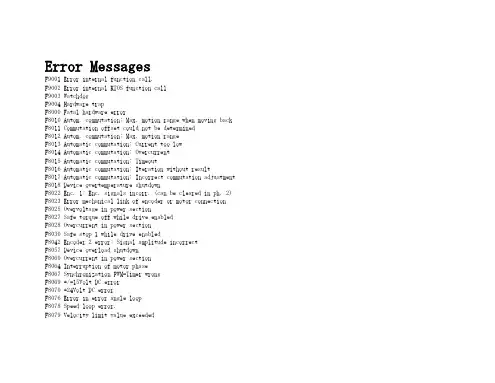
Error MessagesF9001 Error internal function call.F9002 Error internal RTOS function callF9003 WatchdogF9004 Hardware trapF8000 Fatal hardware errorF8010 Autom. commutation: Max. motion range when moving back F8011 Commutation offset could not be determinedF8012 Autom. commutation: Max. motion rangeF8013 Automatic commutation: Current too lowF8014 Automatic commutation: OvercurrentF8015 Automatic commutation: TimeoutF8016 Automatic commutation: Iteration without resultF8017 Automatic commutation: Incorrect commutation adjustment F8018 Device overtemperature shutdownF8022 Enc. 1: Enc. signals incorr. (can be cleared in ph. 2) F8023 Error mechanical link of encoder or motor connectionF8025 Overvoltage in power sectionF8027 Safe torque off while drive enabledF8028 Overcurrent in power sectionF8030 Safe stop 1 while drive enabledF8042 Encoder 2 error: Signal amplitude incorrectF8057 Device overload shutdownF8060 Overcurrent in power sectionF8064 Interruption of motor phaseF8067 Synchronization PWM-Timer wrongF8069 +/-15Volt DC errorF8070 +24Volt DC errorF8076 Error in error angle loopF8078 Speed loop error.F8079 Velocity limit value exceededF8091 Power section defectiveF8100 Error when initializing the parameter handlingF8102 Error when initializing power sectionF8118 Invalid power section/firmware combinationF8120 Invalid control section/firmware combinationF8122 Control section defectiveF8129 Incorrect optional module firmwareF8130 Firmware of option 2 of safety technology defectiveF8133 Error when checking interrupting circuitsF8134 SBS: Fatal errorF8135 SMD: Velocity exceededF8140 Fatal CCD error.F8201 Safety command for basic initialization incorrectF8203 Safety technology configuration parameter invalidF8813 Connection error mains chokeF8830 Power section errorF8838 Overcurrent external braking resistorF7010 Safely-limited increment exceededF7011 Safely-monitored position, exceeded in pos. DirectionF7012 Safely-monitored position, exceeded in neg. DirectionF7013 Safely-limited speed exceededF7020 Safe maximum speed exceededF7021 Safely-limited position exceededF7030 Position window Safe stop 2 exceededF7031 Incorrect direction of motionF7040 Validation error parameterized - effective thresholdF7041 Actual position value validation errorF7042 Validation error of safe operation modeF7043 Error of output stage interlockF7050 Time for stopping process exceeded8.3.15 F7051 Safely-monitored deceleration exceeded (159)8.4 Travel Range Errors (F6xxx) (161)8.4.1 Behavior in the Case of Travel Range Errors (161)8.4.2 F6010 PLC Runtime Error (162)8.4.3 F6024 Maximum braking time exceeded (163)8.4.4 F6028 Position limit value exceeded (overflow) (164)8.4.5 F6029 Positive position limit exceeded (164)8.4.6 F6030 Negative position limit exceeded (165)8.4.7 F6034 Emergency-Stop (166)8.4.8 F6042 Both travel range limit switches activated (167)8.4.9 F6043 Positive travel range limit switch activated (167)8.4.10 F6044 Negative travel range limit switch activated (168)8.4.11 F6140 CCD slave error (emergency halt) (169)8.5 Interface Errors (F4xxx) (169)8.5.1 Behavior in the Case of Interface Errors (169)8.5.2 F4001 Sync telegram failure (170)8.5.3 F4002 RTD telegram failure (171)8.5.4 F4003 Invalid communication phase shutdown (172)8.5.5 F4004 Error during phase progression (172)8.5.6 F4005 Error during phase regression (173)8.5.7 F4006 Phase switching without ready signal (173)8.5.8 F4009 Bus failure (173)8.5.9 F4012 Incorrect I/O length (175)8.5.10 F4016 PLC double real-time channel failure (176)8.5.11 F4017 S-III: Incorrect sequence during phase switch (176)8.5.12 F4034 Emergency-Stop (177)8.5.13 F4140 CCD communication error (178)8.6 Non-Fatal Safety Technology Errors (F3xxx) (178)8.6.1 Behavior in the Case of Non-Fatal Safety Technology Errors (178)8.6.2 F3111 Refer. missing when selecting safety related end pos (179)8.6.3 F3112 Safe reference missing (179)8.6.4 F3115 Brake check time interval exceeded (181)Troubleshooting Guide | Rexroth IndraDrive Electric Drivesand ControlsI Bosch Rexroth AG VII/XXIITable of ContentsPage8.6.5 F3116 Nominal load torque of holding system exceeded (182)8.6.6 F3117 Actual position values validation error (182)8.6.7 F3122 SBS: System error (183)8.6.8 F3123 SBS: Brake check missing (184)8.6.9 F3130 Error when checking input signals (185)8.6.10 F3131 Error when checking acknowledgment signal (185)8.6.11 F3132 Error when checking diagnostic output signal (186)8.6.12 F3133 Error when checking interrupting circuits (187)8.6.13 F3134 Dynamization time interval incorrect (188)8.6.14 F3135 Dynamization pulse width incorrect (189)8.6.15 F3140 Safety parameters validation error (192)8.6.16 F3141 Selection validation error (192)8.6.17 F3142 Activation time of enabling control exceeded (193)8.6.18 F3143 Safety command for clearing errors incorrect (194)8.6.19 F3144 Incorrect safety configuration (195)8.6.20 F3145 Error when unlocking the safety door (196)8.6.21 F3146 System error channel 2 (197)8.6.22 F3147 System error channel 1 (198)8.6.23 F3150 Safety command for system start incorrect (199)8.6.24 F3151 Safety command for system halt incorrect (200)8.6.25 F3152 Incorrect backup of safety technology data (201)8.6.26 F3160 Communication error of safe communication (202)8.7 Non-Fatal Errors (F2xxx) (202)8.7.1 Behavior in the Case of Non-Fatal Errors (202)8.7.2 F2002 Encoder assignment not allowed for synchronization (203)8.7.3 F2003 Motion step skipped (203)8.7.4 F2004 Error in MotionProfile (204)8.7.5 F2005 Cam table invalid (205)8.7.6 F2006 MMC was removed (206)8.7.7 F2007 Switching to non-initialized operation mode (206)8.7.8 F2008 RL The motor type has changed (207)8.7.9 F2009 PL Load parameter default values (208)8.7.10 F2010 Error when initializing digital I/O (-> S-0-0423) (209)8.7.11 F2011 PLC - Error no. 1 (210)8.7.12 F2012 PLC - Error no. 2 (210)8.7.13 F2013 PLC - Error no. 3 (211)8.7.14 F2014 PLC - Error no. 4 (211)8.7.15 F2018 Device overtemperature shutdown (211)8.7.16 F2019 Motor overtemperature shutdown (212)8.7.17 F2021 Motor temperature monitor defective (213)8.7.18 F2022 Device temperature monitor defective (214)8.7.19 F2025 Drive not ready for control (214)8.7.20 F2026 Undervoltage in power section (215)8.7.21 F2027 Excessive oscillation in DC bus (216)8.7.22 F2028 Excessive deviation (216)8.7.23 F2031 Encoder 1 error: Signal amplitude incorrect (217)VIII/XXII Bosch Rexroth AG | Electric Drivesand ControlsRexroth IndraDrive | Troubleshooting GuideTable of ContentsPage8.7.24 F2032 Validation error during commutation fine adjustment (217)8.7.25 F2033 External power supply X10 error (218)8.7.26 F2036 Excessive position feedback difference (219)8.7.27 F2037 Excessive position command difference (220)8.7.28 F2039 Maximum acceleration exceeded (220)8.7.29 F2040 Device overtemperature 2 shutdown (221)8.7.30 F2042 Encoder 2: Encoder signals incorrect (222)8.7.31 F2043 Measuring encoder: Encoder signals incorrect (222)8.7.32 F2044 External power supply X15 error (223)8.7.33 F2048 Low battery voltage (224)8.7.34 F2050 Overflow of target position preset memory (225)8.7.35 F2051 No sequential block in target position preset memory (225)8.7.36 F2053 Incr. encoder emulator: Pulse frequency too high (226)8.7.37 F2054 Incr. encoder emulator: Hardware error (226)8.7.38 F2055 External power supply dig. I/O error (227)8.7.39 F2057 Target position out of travel range (227)8.7.40 F2058 Internal overflow by positioning input (228)8.7.41 F2059 Incorrect command value direction when positioning (229)8.7.42 F2063 Internal overflow master axis generator (230)8.7.43 F2064 Incorrect cmd value direction master axis generator (230)8.7.44 F2067 Synchronization to master communication incorrect (231)8.7.45 F2068 Brake error (231)8.7.46 F2069 Error when releasing the motor holding brake (232)8.7.47 F2074 Actual pos. value 1 outside absolute encoder window (232)8.7.48 F2075 Actual pos. value 2 outside absolute encoder window (233)8.7.49 F2076 Actual pos. value 3 outside absolute encoder window (234)8.7.50 F2077 Current measurement trim wrong (235)8.7.51 F2086 Error supply module (236)8.7.52 F2087 Module group communication error (236)8.7.53 F2100 Incorrect access to command value memory (237)8.7.54 F2101 It was impossible to address MMC (237)8.7.55 F2102 It was impossible to address I2C memory (238)8.7.56 F2103 It was impossible to address EnDat memory (238)8.7.57 F2104 Commutation offset invalid (239)8.7.58 F2105 It was impossible to address Hiperface memory (239)8.7.59 F2110 Error in non-cyclical data communic. of power section (240)8.7.60 F2120 MMC: Defective or missing, replace (240)8.7.61 F2121 MMC: Incorrect data or file, create correctly (241)8.7.62 F2122 MMC: Incorrect IBF file, correct it (241)8.7.63 F2123 Retain data backup impossible (242)8.7.64 F2124 MMC: Saving too slowly, replace (243)8.7.65 F2130 Error comfort control panel (243)8.7.66 F2140 CCD slave error (243)8.7.67 F2150 MLD motion function block error (244)8.7.68 F2174 Loss of motor encoder reference (244)8.7.69 F2175 Loss of optional encoder reference (245)Troubleshooting Guide | Rexroth IndraDrive Electric Drivesand Controls| Bosch Rexroth AG IX/XXIITable of ContentsPage8.7.70 F2176 Loss of measuring encoder reference (246)8.7.71 F2177 Modulo limitation error of motor encoder (246)8.7.72 F2178 Modulo limitation error of optional encoder (247)8.7.73 F2179 Modulo limitation error of measuring encoder (247)8.7.74 F2190 Incorrect Ethernet configuration (248)8.7.75 F2260 Command current limit shutoff (249)8.7.76 F2270 Analog input 1 or 2, wire break (249)8.7.77 F2802 PLL is not synchronized (250)8.7.78 F2814 Undervoltage in mains (250)8.7.79 F2815 Overvoltage in mains (251)8.7.80 F2816 Softstart fault power supply unit (251)8.7.81 F2817 Overvoltage in power section (251)8.7.82 F2818 Phase failure (252)8.7.83 F2819 Mains failure (253)8.7.84 F2820 Braking resistor overload (253)8.7.85 F2821 Error in control of braking resistor (254)8.7.86 F2825 Switch-on threshold braking resistor too low (255)8.7.87 F2833 Ground fault in motor line (255)8.7.88 F2834 Contactor control error (256)8.7.89 F2835 Mains contactor wiring error (256)8.7.90 F2836 DC bus balancing monitor error (257)8.7.91 F2837 Contactor monitoring error (257)8.7.92 F2840 Error supply shutdown (257)8.7.93 F2860 Overcurrent in mains-side power section (258)8.7.94 F2890 Invalid device code (259)8.7.95 F2891 Incorrect interrupt timing (259)8.7.96 F2892 Hardware variant not supported (259)8.8 SERCOS Error Codes / Error Messages of Serial Communication (259)9 Warnings (Exxxx) (263)9.1 Fatal Warnings (E8xxx) (263)9.1.1 Behavior in the Case of Fatal Warnings (263)9.1.2 E8025 Overvoltage in power section (263)9.1.3 E8026 Undervoltage in power section (264)9.1.4 E8027 Safe torque off while drive enabled (265)9.1.5 E8028 Overcurrent in power section (265)9.1.6 E8029 Positive position limit exceeded (266)9.1.7 E8030 Negative position limit exceeded (267)9.1.8 E8034 Emergency-Stop (268)9.1.9 E8040 Torque/force actual value limit active (268)9.1.10 E8041 Current limit active (269)9.1.11 E8042 Both travel range limit switches activated (269)9.1.12 E8043 Positive travel range limit switch activated (270)9.1.13 E8044 Negative travel range limit switch activated (271)9.1.14 E8055 Motor overload, current limit active (271)9.1.15 E8057 Device overload, current limit active (272)X/XXII Bosch Rexroth AG | Electric Drivesand ControlsRexroth IndraDrive | Troubleshooting GuideTable of ContentsPage9.1.16 E8058 Drive system not ready for operation (273)9.1.17 E8260 Torque/force command value limit active (273)9.1.18 E8802 PLL is not synchronized (274)9.1.19 E8814 Undervoltage in mains (275)9.1.20 E8815 Overvoltage in mains (275)9.1.21 E8818 Phase failure (276)9.1.22 E8819 Mains failure (276)9.2 Warnings of Category E4xxx (277)9.2.1 E4001 Double MST failure shutdown (277)9.2.2 E4002 Double MDT failure shutdown (278)9.2.3 E4005 No command value input via master communication (279)9.2.4 E4007 SERCOS III: Consumer connection failed (280)9.2.5 E4008 Invalid addressing command value data container A (280)9.2.6 E4009 Invalid addressing actual value data container A (281)9.2.7 E4010 Slave not scanned or address 0 (281)9.2.8 E4012 Maximum number of CCD slaves exceeded (282)9.2.9 E4013 Incorrect CCD addressing (282)9.2.10 E4014 Incorrect phase switch of CCD slaves (283)9.3 Possible Warnings When Operating Safety Technology (E3xxx) (283)9.3.1 Behavior in Case a Safety Technology Warning Occurs (283)9.3.2 E3100 Error when checking input signals (284)9.3.3 E3101 Error when checking acknowledgment signal (284)9.3.4 E3102 Actual position values validation error (285)9.3.5 E3103 Dynamization failed (285)9.3.6 E3104 Safety parameters validation error (286)9.3.7 E3105 Validation error of safe operation mode (286)9.3.8 E3106 System error safety technology (287)9.3.9 E3107 Safe reference missing (287)9.3.10 E3108 Safely-monitored deceleration exceeded (288)9.3.11 E3110 Time interval of forced dynamization exceeded (289)9.3.12 E3115 Prewarning, end of brake check time interval (289)9.3.13 E3116 Nominal load torque of holding system reached (290)9.4 Non-Fatal Warnings (E2xxx) (290)9.4.1 Behavior in Case a Non-Fatal Warning Occurs (290)9.4.2 E2010 Position control with encoder 2 not possible (291)9.4.3 E2011 PLC - Warning no. 1 (291)9.4.4 E2012 PLC - Warning no. 2 (291)9.4.5 E2013 PLC - Warning no. 3 (292)9.4.6 E2014 PLC - Warning no. 4 (292)9.4.7 E2021 Motor temperature outside of measuring range (292)9.4.8 E2026 Undervoltage in power section (293)9.4.9 E2040 Device overtemperature 2 prewarning (294)9.4.10 E2047 Interpolation velocity = 0 (294)9.4.11 E2048 Interpolation acceleration = 0 (295)9.4.12 E2049 Positioning velocity >= limit value (296)9.4.13 E2050 Device overtemp. Prewarning (297)Troubleshooting Guide | Rexroth IndraDrive Electric Drivesand Controls| Bosch Rexroth AG XI/XXIITable of ContentsPage9.4.14 E2051 Motor overtemp. prewarning (298)9.4.15 E2053 Target position out of travel range (298)9.4.16 E2054 Not homed (300)9.4.17 E2055 Feedrate override S-0-0108 = 0 (300)9.4.18 E2056 Torque limit = 0 (301)9.4.19 E2058 Selected positioning block has not been programmed (302)9.4.20 E2059 Velocity command value limit active (302)9.4.21 E2061 Device overload prewarning (303)9.4.22 E2063 Velocity command value > limit value (304)9.4.23 E2064 Target position out of num. range (304)9.4.24 E2069 Holding brake torque too low (305)9.4.25 E2070 Acceleration limit active (306)9.4.26 E2074 Encoder 1: Encoder signals disturbed (306)9.4.27 E2075 Encoder 2: Encoder signals disturbed (307)9.4.28 E2076 Measuring encoder: Encoder signals disturbed (308)9.4.29 E2077 Absolute encoder monitoring, motor encoder (encoder alarm) (308)9.4.30 E2078 Absolute encoder monitoring, opt. encoder (encoder alarm) (309)9.4.31 E2079 Absolute enc. monitoring, measuring encoder (encoder alarm) (309)9.4.32 E2086 Prewarning supply module overload (310)9.4.33 E2092 Internal synchronization defective (310)9.4.34 E2100 Positioning velocity of master axis generator too high (311)9.4.35 E2101 Acceleration of master axis generator is zero (312)9.4.36 E2140 CCD error at node (312)9.4.37 E2270 Analog input 1 or 2, wire break (312)9.4.38 E2802 HW control of braking resistor (313)9.4.39 E2810 Drive system not ready for operation (314)9.4.40 E2814 Undervoltage in mains (314)9.4.41 E2816 Undervoltage in power section (314)9.4.42 E2818 Phase failure (315)9.4.43 E2819 Mains failure (315)9.4.44 E2820 Braking resistor overload prewarning (316)9.4.45 E2829 Not ready for power on (316)。
ioThinx 4510SeriesAdvanced modular remote I/O adapters with built-in serial portsFeatures and Benefits•Easy tool-free installation and removal•Easy web configuration and reconfiguration•Built-in Modbus RTU gateway function•Supports Modbus/SNMP/RESTful API/MQTT•Supports SNMPv3,SNMPv3Trap,and SNMPv3Inform with SHA-2encryption•Supports up to 32I/O modules•-40to 75°C wide operating temperature model available•Class I Division 2and ATEX Zone 2certifications CertificationsIntroductionThe ioThinx 4510Series is an advanced modular remote I/O product with a unique hardware and software design,making it an ideal solution for a variety of industrial data acquisition applications.The ioThinx 4510Series has a unique mechanical design that reduces the amount of time required for installation and removal,simplifying deployment and maintenance.In addition,the ioThinx 4510Series supports Modbus RTU Master protocol for retrieving field site data from serial meters and also supports OT/IT protocol conversion.Easy Tool-Free Installation and RemovalThe ioThinx 4500Series has a unique mechanical design that reduces the amount of time required for installation and removal.In fact,screwdrivers and other tools are not required for any part of the hardware installation,including mounting the device on a DIN-rail,as well as connecting the wiring for both communication and I/O signal acquisition.Furthermore,no tools are required to remove the ioThinx from a DIN-rail.Removing all of the modules from a DIN-rail is also easy using the latch and release tab.Easy Web Configuration/ReconfigurationFor modular remote I/O setups,one of the greatest difficulties is duplicating configuration settings to the current modules with different module combinations.After adding,moving,or deleting one of the modules,settings of the unchanged modules,including the Modbus address and RESTful APIs to the upper software,need to be reconfigured.The ioThinx 4510’s user-friendly web configuration tool was designed specifically to make configuration and reconfiguration easy;no reconfiguration effort is required for the unchanged modules.In addition,the ioThinx 4510’s web interface supports module/channel unique names.This feature also applies to Modbus TCP,MQTT,and RESTful API,saving users a considerable amount of time on development and deployment.Built-In Modbus RTU Gateway FunctionThe ioThinx4510supports Modbus RTU Master for retrieving field site data from serial meters.After collecting data,users can convert serial data to a variety of protocols,including Modbus TCP,SNMP,MQTT,and RESTful,allowing users to get field site data in their protocol of choice.This two-in-one design reduces system complexity and the amount of space required in the network topology,as well as overall installation time.In addition,you can extend the useful life of legacy devices by connecting them to Ethernet and accessing the devices using a preferred protocol.I/O to IT/OT Protocol ConversionThe ioThinx4510does just what you need by supporting the mostoften-used protocols for retrieving I/O data.Most IT engineers useSNMPv1/v2c/v3,MQTT,or RESTful API protocols,but IA engineersare more familiar with Operational Technologies(OT),such asModbus.The ioThinx4510makes it possible for both IT and OTengineers to conveniently retrieve data from the same I/O device.TheioThinx4510speaks several different protocols,including ModbusTCP for OT engineers,as well as SNMP,MQTT,and RESTful API forIT engineers.The ioThinx4510retrieves I/O data and converts thedata to any of these protocols,allowing you to get your applicationsconnected easily and effortlessly.SpecificationsInput/Output InterfaceButtons Reset buttonExpansion Slots Up to321Isolation3k VDC or2k Vrmspatible with the ioThinx4500Series(45MR)Modules onlyEthernet Interface10/100BaseT(X)Ports(RJ45connector)2,1MAC address(Ethernet bypass)Magnetic Isolation Protection 1.5kV(built-in)Ethernet Software FeaturesConfiguration Options Web Console(HTTP/HTTPS),Windows Utility(IOxpress),MCC ToolIndustrial Protocols Modbus TCP Server(Slave),RESTful API,SNMPv1/v2c/v3,SNMPv1/v2c/v3Trap,SNMPv2c/v3Inform,MQTTManagement SNMPv1/v2c/v3,SNMPv1/v2c/v3Trap,SNMPv2c/v3Inform,DHCP Client,IPv4,HTTP,UDP,TCP/IPSerial InterfaceConnector Spring-type Euroblock terminalSerial Standards RS-232/422/485No.of Ports1x RS-232/422or2x RS-485(2wire)Baudrate1200,1800,2400,4800,9600,19200,38400,57600,115200bpsFlow Control RTS/CTSParity None,Even,OddStop Bits1,2Data Bits8Serial SignalsRS-232TxD,RxD,RTS,CTS,GNDRS-422Tx+,Tx-,Rx+,Rx-,GNDRS-485-2w Data+,Data-,GNDSerial Software FeaturesIndustrial Protocols Modbus RTU MasterSystem Power ParametersPower Connector Spring-type Euroblock terminalNo.of Power Inputs1Input Voltage12to48VDCPower Consumption800mA@12VDCOver-Current Protection1A@25°COver-Voltage Protection55VDCOutput Current1A(max.)Field Power ParametersPower Connector Spring-type Euroblock terminalNo.of Power Inputs1Input Voltage12/24VDCOver-Current Protection 2.5A@25°COver-Voltage Protection33VDCOutput Current2A(max.)Physical CharacteristicsWiring Serial cable,16to28AWGPower cable,12to18AWGStrip Length Serial cable,9mmPower cable,12to13mmHousing PlasticDimensions42.3x99x75mm(1.67x3.9x2.95in)Weight173.5g(0.382lb)Installation DIN-rail mountingEnvironmental LimitsOperating Temperature ioThinx4510:-20to60°C(-4to140°F)ioThinx4510-T:-40to75°C(-40to167°F) Storage Temperature(package included)-40to85°C(-40to185°F)Ambient Relative Humidity5to95%(non-condensing)Altitude Up to4000m2Standards and CertificationsSafety UL61010-2-201EMC EN55032/24EMI CISPR32,FCC Part15B Class AEMS IEC61000-4-2ESD:Contact:4kV;Air:8kVIEC61000-4-3RS:80MHz to1GHz:3V/mIEC61000-4-4EFT:Power:1kV;Signal:0.5kVIEC61000-4-5Surge:Power:2kV;Signal:1kVIEC61000-4-6CS:3VIEC61000-4-8PFMFShock IEC60068-2-27Vibration IEC60068-2-6Hazardous Locations Class I Division2,ATEXDeclarationGreen Product RoHS,CRoHS,WEEEMTBFTime1,451,040hrsStandards Telcordia SR3322.Please contact Moxa if you require products guaranteed to function properly at higher altitudes.Warranty Period5yearsDetails See /warranty Package ContentsDevice1x ioThinx4510Series remote I/O Installation Kit1x terminal block,5-pin,5.00mm1x terminal block,5-pin,3.81mm Documentation1x quick installation guide1x warranty card DimensionsTop/Side/Bottom PanelsOrdering InformationModel Name Ethernet Interface Serial Interface No.of Support I/O Modules Operating Temp. ioThinx45102x RJ45RS-232/RS-422/RS-48532-20to60°C ioThinx4510-T2x RJ45RS-232/RS-422/RS-48532-40to75°C Accessories(sold separately)I/O Modules45MR-1600Module for the ioThinx4500Series,16DIs,24VDC,PNP,-20to60°C operating temperature45MR-1600-T Module for the ioThinx4500Series,16DIs,24VDC,PNP,-40to75°C operating temperature45MR-1601Module for the ioThinx4500Series,16DIs,24VDC,NPN,-20to60°C operating temperature45MR-1601-T Module for the ioThinx4500Series,16DIs,24VDC,NPN,-40to75°C operating temperature45MR-2404Module for the ioThinx4500Series,4relays,form A,-20to60°C operating temperature45MR-2404-T Module for the ioThinx4500Series,4relays,form A,-40to75°C operating temperature45MR-2600Module for the ioThinx4500Series,16DOs,24VDC,sink,-20to60°C operating temperature45MR-2600-T Module for the ioThinx4500Series,16DOs,24VDC,sink,-40to75°C operating temperature45MR-2601Module for the ioThinx4500Series,16DOs,24VDC,source,-20to60°C operating temperature45MR-2601-T Module for the ioThinx4500Series,16DOs,24VDC,source,-40to75°C operating temperature45MR-2606Module for the ioThinx4500Series,8DIs,24VDC,PNP,8DOs,24VDC,source,-20to60°C operatingtemperature45MR-2606-T Module for the ioThinx4500Series,8DIs,24VDC,PNP,8DOs,24VDC,source,-40to75°C operatingtemperature45MR-3800Module for the ioThinx4500Series,8AIs,0to20mA or4to20mA,-20to60°C operating temperature 45MR-3800-T Module for the ioThinx4500Series,8AIs,0to20mA or4to20mA,-40to75°C operating temperature 45MR-3810Module for the ioThinx4500Series,8AIs,-10to10V or0to10V,-20to60°C operating temperature 45MR-3810-T Module for the ioThinx4500Series,8AIs,-10to10V or0to10V,-40to75°C operating temperature 45MR-4420Module for the ioThinx4500Series,4AOs,0to10V or0to20mA or4to20mA,-20to60°C operatingtemperature45MR-4420-T Module for the ioThinx4500Series,4AOs,0to10V or0to20mA or4to20mA,-40to75°C operatingtemperature45MR-6600Module for the ioThinx4500Series,6RTDs,-20to60°C operating temperature45MR-6600-T Module for the ioThinx4500Series,6RTDs,-40to75°C operating temperature45MR-6810Module for the ioThinx4500Series,8TCs,-20to60°C operating temperature45MR-6810-T Module for the ioThinx4500Series,8TCs,-40to75°C operating temperaturePower Modules45MR-7210Module for the ioThinx4500Series,system and field power inputs,-20to60°C operating temperature 45MR-7210-T Module for the ioThinx4500Series,system and field power inputs,-40to75°C operating temperature 45MR-7820Module for the ioThinx4500Series,potential distributor module,-20to60°C operating temperature 45MR-7820-T Module for the ioThinx4500Series,potential distributor module,-40to75°C operating temperature©Moxa Inc.All rights reserved.Updated Oct13,2021.This document and any portion thereof may not be reproduced or used in any manner whatsoever without the express written permission of Moxa Inc.Product specifications subject to change without notice.Visit our website for the most up-to-date product information.。
Symbol Test Conditions Maximum RatingsV CES T J = 25︒C to 150︒C600 V V CGR T J = 25︒C to 150︒C, R GE = 1M Ω600 V V GES Continuous ±20 V V GEM Transient±30 V I C25T C = 25︒C (Chip Capability)400 A I C110T C = 110︒C190 A I LRMS Terminal Current Limit 200 A I CM T C = 25︒C, 1ms800 A SSOA V GE = 15V, T VJ = 125︒C, R G = 0.5Ω I CM = 400 A (RBSOA)Clamped Inductive Load @ 0.8 • V CESP C T C = 25︒C830 WT J -55 ... +150 ︒C T JM 150 ︒CT stg -55 ... +150 ︒CV ISOL50/60Hz t = 1min 2500 V~I ISOL ≤ 1mAt = 1s 3000 V~M d Mounting Torque1.5/13 Nm/lb.in. Terminal Connection Torque (M4) 1.3/11.5 Nm/lb.in.Weight30gSymbol Test Conditions Characteristic Values (T J = 25︒C, Unless Otherwise Specified) Min. Typ. Max.BV CES I C = 1mA, V GE = 0V 600 V V GE(th)I C= 250uA, V CE = V GE3.0 5.5 VI CES V CE = V CES , V GE = 0V250 μAT J = 125︒C 2.5 mAI GES V CE = 0V, V GE = ±20V ±400 nAV CE(sat)I C= 100A, V GE = 15V, Note 1 1.05 1.25 V I C= 400A 1.55 VGenX3TM 600V IGBTIXGN400N60A3V CES = 600V I C25= 400A V CE(sat)≤ 1.25VSOT-227B, miniBLOCG = Gate, C = Collector, E = Emitter① either emitter terminal can be used asMain or Kelvin EmitterGE ①E ①CE153432Ultra-Low-Vsat PT IGBT for up to 5kHz SwitchingEFeatures●Optimized for Low Conduction losses ●Square RBSOA●High Current Capability ●Isolation Voltage 3000 V~●International Standard PackageA dvantages●High Power Density●Low Gate Drive RequirementApplications●Power Inverters●UPS●Motor Drives ●SMPS●PFC Circuits ●Battery Chargers ●Welding Machines ●Lamp Ballasts●Inrush Current Protection CircuitsIXYS Reserves the Right to Change Limits, Test Conditions, and Dimensions.Symbol Test ConditionsCharacteristic ValuesNote 1.Pulse test, t ≤ 300μs; duty cycle, d ≤ 2%.KJ DSTPV M W NURQEcBAF G H NUT MATERIAL:STANDARD - Low carbon steel with Ni plating.OPTIONAL - Brass Nut is available PART NUMBER-BNO M4-7 NUT (4 PLACES)IXYS Reserves the Right to Change Limits, Test Conditions, and Dimensions.。
1NCM45x0-2 Network Control Module Commissioning Guide Document Introduction. . . . . . . . . . . . . . . . . . . . . . . . . . . . . . . . . . . . . . . . . . . . . . . . .5Related Documentation. . . . . . . . . . . . . . . . . . . . . . . . . . . . . . . . . . . . . . . . . . . . . . . . .5NCM45x0-2 Commissioning Overview. . . . . . . . . . . . . . . . . . . . . . . . . . . . . . . . . . . . .6About the NCM45x0-2 Network Control Module (NCM) . . . . . . . . . . . . . . . . . . . . . . . . . . 6Metasys Network with the NCM45x0-2. . . . . . . . . . . . . . . . . . . . . . . . . . . . . . . . . . . . . . . . 7Differences between NCM45x0-2 and NCM300 Series Controllers. . . . . . . . . . . . . . . . . 8Required Software. . . . . . . . . . . . . . . . . . . . . . . . . . . . . . . . . . . . . . . . . . . . . . . . . . . . . . . . 9Supported NCM Types . . . . . . . . . . . . . . . . . . . . . . . . . . . . . . . . . . . . . . . . . . . . . . . . . . . . 9Supported Operator Devices . . . . . . . . . . . . . . . . . . . . . . . . . . . . . . . . . . . . . . . . . . . . . . 10Supported Communication Buses. . . . . . . . . . . . . . . . . . . . . . . . . . . . . . . . . . . . . . . . . . 10Database Generation. . . . . . . . . . . . . . . . . . . . . . . . . . . . . . . . . . . . . . . . . . . . . . . . . . . . . 10Memory. . . . . . . . . . . . . . . . . . . . . . . . . . . . . . . . . . . . . . . . . . . . . . . . . . . . . . . . . . . . . . . . 11Microprocessor . . . . . . . . . . . . . . . . . . . . . . . . . . . . . . . . . . . . . . . . . . . . . . . . . . . . . . . . . 11System Status LEDs . . . . . . . . . . . . . . . . . . . . . . . . . . . . . . . . . . . . . . . . . . . . . . . . . . . . . 11Communications . . . . . . . . . . . . . . . . . . . . . . . . . . . . . . . . . . . . . . . . . . . . . . . . . . . . . . . . 11N1 Local Area Network . . . . . . . . . . . . . . . . . . . . . . . . . . . . . . . . . . . . . . . . . . . . . . . . . . . . 11N2 Communications. . . . . . . . . . . . . . . . . . . . . . . . . . . . . . . . . . . . . . . . . . . . . . . . . . . . . . . 12LON Communications . . . . . . . . . . . . . . . . . . . . . . . . . . . . . . . . . . . . . . . . . . . . . . . . . . . . . 12Operator Terminal Support . . . . . . . . . . . . . . . . . . . . . . . . . . . . . . . . . . . . . . . . . . . . . . . . . 13Network Terminal Support. . . . . . . . . . . . . . . . . . . . . . . . . . . . . . . . . . . . . . . . . . . . . . . . . . 13RS232C Ports . . . . . . . . . . . . . . . . . . . . . . . . . . . . . . . . . . . . . . . . . . . . . . . . . . . . . . . . . . . 14External Modem. . . . . . . . . . . . . . . . . . . . . . . . . . . . . . . . . . . . . . . . . . . . . . . . . . . . . . . . . . 15Battery Pack. . . . . . . . . . . . . . . . . . . . . . . . . . . . . . . . . . . . . . . . . . . . . . . . . . . . . . . . . . . . 16Power Up/Power Down Behavior . . . . . . . . . . . . . . . . . . . . . . . . . . . . . . . . . . . . . . . . . . . 16Resetting and Reloading the NCM45x0-2 . . . . . . . . . . . . . . . . . . . . . . . . . . . . . . . . . . . . 16NCM45x0-2 Network Control ModuleCommissioning GuideCode No. LIT-12011176Software Release 3.0Issued May 2, 2007Supersedes September 29, 2006Communication Port Comparison: NCM45x0-2 and NCM300 Series . . . . . . . . . . . . . . 17 Cable Guidelines for RS232C Port Devices. . . . . . . . . . . . . . . . . . . . . . . . . . . . . . . . . . . 17 Configured or Unconfigured OWS. . . . . . . . . . . . . . . . . . . . . . . . . . . . . . . . . . . . . . . . . . . . 18 Operator Terminal . . . . . . . . . . . . . . . . . . . . . . . . . . . . . . . . . . . . . . . . . . . . . . . . . . . . . . . . 18 Network Terminal. . . . . . . . . . . . . . . . . . . . . . . . . . . . . . . . . . . . . . . . . . . . . . . . . . . . . . . . . 19 External Modem. . . . . . . . . . . . . . . . . . . . . . . . . . . . . . . . . . . . . . . . . . . . . . . . . . . . . . . . . . 19 Printers. . . . . . . . . . . . . . . . . . . . . . . . . . . . . . . . . . . . . . . . . . . . . . . . . . . . . . . . . . . . . . . . . 19 NCM Commissioning. . . . . . . . . . . . . . . . . . . . . . . . . . . . . . . . . . . . . . . . . . . . . . . . . . . . . 21 NCM Configuration . . . . . . . . . . . . . . . . . . . . . . . . . . . . . . . . . . . . . . . . . . . . . . . . . . . . . . 21 NCM Default User Name and Password . . . . . . . . . . . . . . . . . . . . . . . . . . . . . . . . . . . . . 22 Detailed Procedures . . . . . . . . . . . . . . . . . . . . . . . . . . . . . . . . . . . . . . . . . . . . . . . . . . 22 Setting the N2 End-of-Line Switch. . . . . . . . . . . . . . . . . . . . . . . . . . . . . . . . . . . . . . . . . . 22 Downloading the NCM45x0-2 Code . . . . . . . . . . . . . . . . . . . . . . . . . . . . . . . . . . . . . . . . . 23 Configuring the NCM with NCSETUP. . . . . . . . . . . . . . . . . . . . . . . . . . . . . . . . . . . . . . . . 31 Configuring NCM for Use on Metasys Network Using DDL. . . . . . . . . . . . . . . . . . . . . . 35 Connecting NCM to the Metasys Network. . . . . . . . . . . . . . . . . . . . . . . . . . . . . . . . . . . . . . 36 Verifying NCM Has Downloaded. . . . . . . . . . . . . . . . . . . . . . . . . . . . . . . . . . . . . . . . . . . . . 36 Verifying Online Status of NCM, Devices, and Objects. . . . . . . . . . . . . . . . . . . . . . . . . . . . 37 Verifying the NCM45x0-2 Code Base. . . . . . . . . . . . . . . . . . . . . . . . . . . . . . . . . . . . . . . . 37 Changing the NCM Default Password . . . . . . . . . . . . . . . . . . . . . . . . . . . . . . . . . . . . . . . 37 Replacing an NCM350/361 with an NCM45x0-2. . . . . . . . . . . . . . . . . . . . . . . . . . . . . . . . 38 Replacing an NCM That Uses the ARCNET Network with an NCM45x0-2 . . . . . . . . . . 39 Replacing a Defective NCM45x0-2. . . . . . . . . . . . . . . . . . . . . . . . . . . . . . . . . . . . . . . . . . 39 Migrating an NCM to an NAE45 . . . . . . . . . . . . . . . . . . . . . . . . . . . . . . . . . . . . . . . . . . . . 39 Troubleshooting . . . . . . . . . . . . . . . . . . . . . . . . . . . . . . . . . . . . . . . . . . . . . . . . . . . . . 40 Corrupted NCM Memory . . . . . . . . . . . . . . . . . . . . . . . . . . . . . . . . . . . . . . . . . . . . . . . . . . 40 Network Connection Related Problems. . . . . . . . . . . . . . . . . . . . . . . . . . . . . . . . . . . . . . 40 NCM45x0-2 Troubleshooting Guide. . . . . . . . . . . . . . . . . . . . . . . . . . . . . . . . . . . . . . . . . 41 NCM Diagnostic Procedures. . . . . . . . . . . . . . . . . . . . . . . . . . . . . . . . . . . . . . . . . . . . . . . 43 NCM LED Status Indicators. . . . . . . . . . . . . . . . . . . . . . . . . . . . . . . . . . . . . . . . . . . . . . . . . 442NCM45x0-2 Network Control Module Commissioning GuideNCM Startup/Shutdown Sequence . . . . . . . . . . . . . . . . . . . . . . . . . . . . . . . . . . . . . . . . . . . 45 NCM Log Files . . . . . . . . . . . . . . . . . . . . . . . . . . . . . . . . . . . . . . . . . . . . . . . . . . . . . . . . . . 46 Technical Specifications . . . . . . . . . . . . . . . . . . . . . . . . . . . . . . . . . . . . . . . . . . . . . .47 NCM45x0-2 Model . . . . . . . . . . . . . . . . . . . . . . . . . . . . . . . . . . . . . . . . . . . . . . . . . . . . . . . 47NCM45x0-2 Network Control Module Commissioning Guide34NCM45x0-2 Network Control Module Commissioning GuideNCM45x0-2 Network Control ModuleCommissioning GuideDocument IntroductionThis document describes how to commission a Network Control Module(NCM45x0-2) in a Metasys® network. The NCM45x0-2 emulates theNCM350/361 and operates with other Network Control Modules (NCMs),Network Control Units (NCUs), Network Expansion Units (NEUs), NetworkIntergration Engines (NIEs), and Operator Workstations (OWSs) in the facility.This document does not describe how to mount, wire, or turn on the NCM. Also,this document does not describe how to build or download the NCM database, orhow to configure an NCM to monitor and control a Building Automation System(BAS).Related DocumentationTable1 lists documents related to the Metasys system.Table 1: Related DocumentationFor Information On See Document LIT or Part Number Installing the NCM45x0-2NCM45x0-2 Series Network ControlModule Installation InstructionsPart No. 24-10249-18Installing the NCM45x0-2 as a Replacement to Existing NCM350/361NCM45x0-2 Series Network ControlModule Installation InstructionsPart No. 24-10249-18Installing the NCM45x0-2 as aReplacement to an NCM That Usesthe ARCNET® NetworkN1 Ethernet/IP Network Technical Bulletin LIT-6360175Using NCSETUP with the NCM45x0-2NCSETUP for Windows® OperatingSystem Technical BulletinLIT-6360251dUnderstanding How the N2 Bus Is Integrated to the NCM N2 Communications Bus TechnicalBulletinLIT-636018Understanding How the LON Network Is Integrated to the NCM L ON W ORKS® Network Layout TechnicalBulletinLIT-1162150Overview of N2 Bus Controllers Technical Bulletin for each N2 Bus fieldcontrollerVarious Setting Up NCM Database DDL User’s Manual (offline method)LIT-630010Operator Workstation User’s Manual(online method)LIT-120165Creating Processes for the NCM to Execute GPL Programmer’s ManualJC BASIC Programmer’s ManualLIT-631010LIT-632010NCM45x0-2 Network Control Module Commissioning Guide5NCM45x0-2 Network Control Module Commissioning Guide 6NCM45x0-2 Commissioning OverviewAbout the NCM45x0-2 Network Control Module (NCM)The Network Control Module 4500 Series (NCM45x0-2) is a fullyuser-programmable supervisory controller on the Metasys network. The NCM coordinates and supervises the control activities for objects and control loops connected to it from field controllers such as those that belong to the family of Application Specific Controllers (ASCs). Table 1 shows the models available for the NCM45x0-2 Series.The NCM integrates three streams of information:•system, database, and global information •application programs (Graphic Programming Language and JCBASIC processes)•data and Input/Output (I/O) information arriving from the communicationportsIn addition, the NCM, via the N1 Local Area Network (LAN), can controlactivities for objects located in other NCMs. An example of exchanged control would be objects shed or restored by the Demand Limiting/Load Rolling feature.Note:Because the NCM45x0-2 emulates the operation of the NCM350/361,existing Metasys tools such as NCSETUP and the Metascan DataCollection Tool can be used with the NCM45x0-2. However, the Metasys software does not recognize the NCM45x0-2 as a new device type; rather, it identifies the NCM45x0-2 as an NCM350.Table 2: NCM45x0-2 Series ModelsProduct CodeNumber 11.All models are also available in a Buy American version (add a G after the code number). Forthe European version, add an E after the code number. For repair parts, add -702 after the code number.Description MS-NCM45x0-2(Base features ofeach NCM45x0)NCM Network Control Module: Requires a 24 VAC power supply. Each model includes two RS232C serial ports, one USB serial port (unused), one Ethernet port, and an MS-BAT1020-0 Data Protection Battery. MS-NCM4510-2100 devices per NCM (60 to 200 TC-9100s)50 devices per repeater with two repeaters cascaded MS-NCM4520-2Includes a L ON W ORKS port and supports one L ON W ORKS trunk. Up to 127 devices are supported on the L ON W ORKS port.Metasys Network with the NCM45x0-2The NCM45x0-2 exists on the Ethernet portion of the N1 Network. Figure1 showsan example of this type of configuration with connections to some of the supporteddevices. As shown, a network that uses both ARCNET and Ethernet nodes requiresa Metasys Ethernet Router to handle communication between the two segments ofthe network.Figure 1: NCM45x0-2 with Other System ComponentsNCM45x0-2 Network Control Module Commissioning Guide7Differences between NCM45x0-2 and NCM300 Series Controllers For those who are familiar with the NCM300 Series controllers, the following section outlines the most important differences between the older models and the NCM45x0-2. If you are looking specifically for details on the communication options, see Table5.•The NCM4510-2 model supports two NCM code download types: General with OT(Operator Terminal) and General with NT (Network Terminal). TheNCM4520-2 model supports one NCM code download type: General with NT.No other NCM types are available on either model.•The NCM45x0-2 uses Ethernet exclusively. No ARCNET® model is available.•The NCM4510-2 model offers one N2 Bus, not two. The NCM4520-2 model offers one LON Trunk.•The Ethernet, N2 Bus, and LON Network components are built into the motherboard; separate network cards are not required.•Memory is located on the motherboard and cannot be added to or removed.•The NCM45x0-2 offers two serial ports: RS232C A/Port 3 andRS232C B/Port 5. Port 3 on the older models is equivalent toRS232C A/Port 3, and Port 5 is equivalent to RS232C B/Port 5. A deviceconnected to Port 3 on the NCM350/361 can be moved to RS232C A/Port 3 on the NCM45x0-2. A device connected to Port 5 on the NCM350/361 can bemoved to RS232C B/Port 5 on the NCM45x0-2. Serial Ports 2, 4, and 6 on the NCM350/361 models are not offered on the NCM45x0-2.•N1 communication at 10 or 100 Mbps is supported. Connection at 100 Mbps greatly increases the speed of uploads and downloads.•The NCM45x0-2 is powered with a 24 V AC power transformer, ordered separately. The adapter requires a standard power outlet near the NCM.•The code for the NCM45x0-2 is downloaded and updated with a tool called the Metasys NCM Update Utility, available on the Branch Purchasing Package(BPP). If you try to download both code and data from an OperatorWorkstation, only the data is downloaded.•To return the NCM to factory condition, the device must be reflashed with the Metasys NCM Update Utility. There is no switch or jumper on theNCM45x0-2 that can be used to return the unit to its default factory condition (Gate 1, Node 99). After the device is reflashed, it must be reconfigured withNCSETUP, because the flash process erases the NOVRAM settings.•The NCM45x0-2 is smaller than the NCM300 Series and in most situations can fit in the same location as the NCM300 if it is replacing it.•The N2 Bus terminal connector on the NCM45x0-2 is called FC Bus (Field Controller Bus). Also, this connector has four terminals, including atermination for an optional shield.8NCM45x0-2 Network Control Module Commissioning Guide•Two Light-Emitting Diodes (LEDs) on the NCM45x0-2 indicate failure: Fault and Batt Fault. The LEDs do not indicate diagnostic error codes, nor do theyindicate the network address of the NCM while it is booting. For details, seeNCM LED Status Indicators.•Do not push the Reload switch (Figure2) on the NCM to initiate a devicereload. It does not have the same function as the Reload button on theNCM300.•The NCM’s error log records the use of any invalid ports that may have been configured on the NCM45x0-2. To determine if an invalid port is defined, openthe NCM’s error log file from the Operator Workstation and look for the entryError Adding IO Device. Even though the controller functions normally withinvalid ports defined, it is good practice to correct invalid port definition.•If Serial Port 3 (RS232C A/Port 3 on the NCM45x0-2) is selected for OT use, a direct connection with NCSETUP to that port is no longer available. In thatcase, use WNCSETUP from the Operator Workstation.•The NCM45x0-2 does not support remote NT connections. This capability is lost if an NCM45x0-2 replaces an existing NCM300 that uses remote NTconnections.Required SoftwareThe NCM45x0-2 requires Metasys Person-Machine Interface (PMI) Release 12.04software. The M-Series Workstation Software at Release 5.4 is also supported.With either system, be sure that the most recent Quick Patch has been applied.Supported NCM TypesThe two NCM code download types that the NCM4510-2 (N2 Bus version) modelsupports are General with OT and General with NT. For the NCM4520-2 (LONversion) model, only the General with NT type is supported. No other NCMdownload types are supported on either model.Both NCM types support the following N2 Bus devices: Air Handling Units(AHUs), Variable Air V olume (V A V) controllers, Variable Air V olume ModularAssemblies (VMAs), Unitary (UNT) controllers, Lab and Central Plant (LCP)controllers, Phoenix Lab and Fume Hood Interface Modules (PHX), DC-9100s,DR9100s, DX-9100s, TC9100s, Intelligent Fire Controller (IFC-2020 orIFC-1010) panel, Extension Modules (XTM), Generic Vendor Devices (VNDs),and Metasys Integrator® units.For the NCM with the LON Network, these devices are supported: DX9200,TCU1200, VMA1200 and other non Johnson Controls® L ON W ORKS compatibledevices.Unsupported devices include: Intelligent Lighting Controller (ILC), IntelligentAccess Controller (IAC-600), N2 Dialer Module (NDM), and DX9120/DX9121.The various migration NCM types, such as Network Port, S2 Migration, and JC/85Gateway, are also not supported.NCM45x0-2 Network Control Module Commissioning Guide9Supported Operator DevicesThe three user devices that can communicate with the NCM are the OperatorWorkstation, Operator Terminal, and Network Terminal. When connected, these devices can display, schedule, and control applications connected to this and any other NCMs on the network.Supported Communication BusesThe NCM supports the N2 Bus or LON network. It does not support N2E (N2 on Echelon® network), L2, or a second N2 Bus.Database GenerationData Definition Language (DDL) is used to generate the NCM database offline. If the online method is preferred, the Operator Workstation can be used. Once the NCM is configured with NCSETUP, its database can be downloaded from the workstation. Unlike older NCM models, the code for the NCM45x0-2 is notdownloaded from the Operator Workstation. This function is accomplished with the Metasys NCM Update Utility. (For details, see Downloading the NCM45x0-2 Code.) If you try to download code and data from the workstation, only the data portion is downloaded.Figure2 illustrates the basic components of the NCM. These components are referred to throughout this document.Figure 2: NCM45x0-2 Components10NCM45x0-2 Network Control Module Commissioning GuideMemoryThe NCM45x0-2 contains 128 MB SDRAM and 128 MB of Flash memory on the motherboard, which cannot be added to or removed. The NCM45x0-2 is designed to emulate the capacity of the NCM350/361 with 10 MB installed. Also, like the NCM350/361, the NCM45x0-2 allocates 8 MB of available memory for use by the application database.MicroprocessorThe microprocessor applies the various supervisory programs to the combined data, and exercises control over the modules and devices that connect to the NCM via a local bus. This supervision and control operate in the same manner when either of the NCM code types is selected.The NCM45x0-2’s Central Processing Unit (CPU) has more processing bandwidth than the older NCM300 Series controllers. This is evident when viewing the idle time reported by NCSETUP. The idle time for the NCM45x0-2 may be higher than that reported by an NCM350 when running the same database; however, the idle time as reported by each device is accurate.System Status LEDsThe NCM has nine LEDs that indicate power and status information (Figure3).Figure 3: NCM45x0-2 Status IndicatorsFor the purpose of each LED, see Table8.CommunicationsThe I/O subsystem supports a multi-user environment consisting of networkconnections (N1 and integrated N2 or LON) and direct I/O communication (OT, NT, and printer using the RS232C ports).N1 Local Area NetworkThe N1 LAN allows communication with both OWSs and other NCMs on the network. The Ethernet circuitry is built into the NCM45x0-2 motherboard.Each NCM and OWS on the system contains a Node Manager task, whoseresponsibilities include:•broadcasting once per minute that it is still online•listening to other node managers to track on and offline devices•issuing a time stamp for every global database in its memory•comparing the time stamps of its own databases to the received time stamps of other node managers’ databases, and updating the current database if necessary •monitoring the printer for online or offline statusThe device with the lowest address number on the network issues time and date information every 4 hours to ensure system synchronization. A clock/calendar chip backs up time and date information. This Node Manager also monitors broadcasts and issues online/offline advisories.In the event of a severed N1 network, each separated LAN forms an independent network.N2 CommunicationsThe NCM4510-2 has a built-in Field Controller (FC) bus called the N2 Bus(RS-485) that allows it to communicate with a variety of field controllers. Devices on the N2 Bus constitute a local network, controlled by the NCM. The NCM polls the devices according to a user-set priority level, which is set at each device’s Definition window. In most cases, the default priority level is sufficient.The N2 connects in a daisy-chain fashion and provides the transmission medium for external devices (field controllers such as the AHU, UNT, LCP, DX-9100, DCM, and IFC-1010/IFC-2020 Intelligent Fire Controller).Each end of the N2 Bus is terminated with an End-of-Line (EOL) termination resistor provided by a switch. For information on setting the N2 EOL switch, see Setting the N2 End-of-Line Switch in this document.LON CommunicationsThe NCM4520-2 has a built-in LON network interface that allows it tocommunicate with a L ON W ORKS network of compatible devices. The L ON W ORKS network carries all communication between the NCM and L ON W ORKS compatible devices and between the devices themselves. The types of data that are transferred across the network include:•commands from the NCM to the devices•responses from the devices to the NCM, including identification and requested data values•time synchronization messages from the NCM•analog and binary point data shared between devicesThe L ON W ORKS network uses EOL terminators to balance the communication signals. For details, refer to the L ON W ORKS Network Layout Technical Bulletin (LIT-1162150).Operator Terminal SupportAn Operator Terminal can be connected to either of the RS232C ports, but if you select RS232C B/Port 5, direct connection to the RS232C A/Port 3 is still available with NCSETUP. Both the direct-connect and dial-up connect options aresupported. To use the OT function, select General with OT and its serial port while commissioning the NCM with NCSETUP. All OT functions, such asdisplaying summary and trend information, commanding objects, and performing schedule operations, are available. The choices for running the OT software are:•VT100 terminal or VT220 terminal running in VT100 mode•computer running VT100 emulation software, such as provided by HyperTerminal, an application that comes with all Microsoft® Windowsoperating systemsFor full details on using the OT with the NCM, refer to the Operator Terminal Technical Bulletin (LIT-636015).Network Terminal SupportA Network Terminal can be connected to RS232C B/Port 5 to provide for allavailable NT functions; however, there are a few restrictions:•Connect the NT to RS232C B/Port 5 only; communication is at 9600 baud.•Use the special cable kit to connect the NT to the NCM45x0-2 serial port (refer to Table 8 in the NCM45x0-2 Series Network Control Module InstallationInstructions [Part No. 24-10249-18]). The kit contains a serial port adapter anda power adapter. The serial adapter is connected to the RS232C B/Port 5 porton the NCM (Figure4), and the standard NT cable connects between one of the NT jacks and the back of the serial adapter. This cable provides the dataconnection. The power adapter connects between AC power and the other NT jack, to provide the power connection. The NT jacks are identical, whichmeans either jack can accept data or power.•Provide AC power for the NCM4500 NT Cable Kit within 6 feet of the NCM.•Connect to the NT locally only; remote connection to the NT via modems is not supported.•Keep the RS232C B/Port 5 as an unconfigured port. If configured for a purpose, NT operations are not available.RS232C PortsTwo RS232C serial ports on the NCM45x0-2 provide input/output at standard RS232C levels using the DTE protocol. They provide for several communication options. See Table 3.Table 3: RS232C Port Communication Options (See Figure 1.)PortMaximum Baud RateSupported ApplicationRS232C A/Port 319,200 bpsPrinter (direct or dial-up connection)Configured OWS (direct or dial-up connection)Unconfigured OWS (direct connection)Operator Terminal (direct or dial-up connection)Note: This port is equivalent to Port 3 on an NCM350/361.Printer (direct or dial-up connection)Configured OWS (direct or dial-up connection)Operator Terminal (direct or dial-up connection)Network Terminal (direct connection only)Note: This port is equivalent to Port 5 on an NCM350/361.RS232C B/Port 556,700 bps 11.Do not select a baud of 28,800 bps. It is not supported.Figure 4: Connecting NT to NCM45x0-2 with Cable KitTable 4 lists the port restrictions for each supported application.External ModemThe NCM45x0-2 supports the use of two external modems connected to its RS232C ports. The modems can provide for remote annunication of alarms to a printer or provide for remote dial-in by a user device, either an Operator Workstation or Operator Terminal.Keep the following in mind when using an external modem with an NCM45x0-2: •A specific initialization string for the particular modem you are using must be configured with NCSETUP. Refer to the NCSETUP for Windows Operating System Technical Bulletin (LIT-6360251d).•The external modem is connected directly to either port by using a cable with the proper pinouts (see Cable Guidelines for RS232C Port Devices ). Once the port is configured for a modem, it is no longer available for direct connect diagnostics using NCSETUP.•Only one dial-up OWS, Operator Terminal (OT), or printer can be connected to the NCM.•The baud rate for a modem connected to a dial-up printer must be programmed to connect at 9600 bps using the S37=9 parameter.Table 4: Serial Port Restrictions for each ApplicationApplicationMaximum Number of ConnectionsNotesOWS Direct - Configured2A configured OWS is an OWS defined in the database. Each port can support one configured OWS.OWS Direct - Unconfigured 1An unconfigured OWS is an OWS that is not defined in the database (for example, a laptop computer). Use it to run logs and summaries, or to download the database. It cannot be connected directly to the Ethernet LAN.OWS Dial 1 A remotely connected OWS on one of the serial ports is supported. Requires a pair of compatible modems.OT Direct 1You cannot have both a direct and dial-up OT on the same NCM.OT Dial 1Requires a pair of compatible modems. You cannot have both a direct and dial-up OT on the same NCM.NT Direct1Can only be used by NT application.NCM Printer Direct 1 A directly connected printer on one of the serial ports is supported.NCM Printer Dial1A remotely connected printer on one of the serial ports is supported. Requires a pair of compatible modems.。
NCM4510网络控制模块网络控制模块NCM是NCU的主处理器。
完全可由用户编程。
它负责监控连接到NCU上的点与控制回路,以及连接在局部总线上进行通信的各种类型的控制器。
网络控制模块(NCM)是NCU的主要部件,它装备高速80386微处理器,其内存(RAM)可由8MB扩展至10MB,它带有自诊断功能,并有72小时后备电池。
选择NCM的配置,可以将它作为N1网络上的一个节点或者一个独立的控制器(将其它系统与置于METASYS的控制之下或作为用户的其他系统与METASYS的接口)。
由电池支持的NCM存储器,用于存储应用程序,用户数据库和点的历史记录。
每个NCM都具有如下描述的特性,以此来协调整个系统效率,时时提醒及不断地监控,以确保用户的安全和舒适。
特点:能和其他NCM及工作站之间进行快速有效地通讯。
由于模块化设计,便于安装。
由电池存储应用程序避免断电丢失。
收集和存储历史趋势、设备运行时间及能源消耗。
让用户能够很好地理解所有信息。
前面面板上的状态显示LED保证模块能够正常的运行。
NCM能够支持N1 ETHERNET及N1 ARCNET总线。
NCM-W网络通讯模块概述网络通讯模块(NCM)为IFC2-3030火灾报警控制器及JNAC2(网络控制告警器)提供接口连接到FAS网络-两种NCM可供选择:NCM-W(通过双绞线连接到网络节点),NCM-F(通过光纤连接到网络节点).NCM-W特性:-支持双绞线连接-支持环型或分支型号网络布线-两个可编程的数据阈值-与网络节点间具有电气隔离-可插拔接线端子-可插拔式服务连接器(信号可以直接通过),用于必须移动的节点-312.5KBps的传输率-各节点数据再生-两个网络接口允许同时连接到火灾报警控制器及计算机-允许软件和数据库在FAS网络上上传/下载。
NCM45x0-2 Network Control ModuleCode No. LIT-1900362Issued October 4, 2010DescriptionThe NCM45x0-2 Series Network Control Module is a fully user-programmablesupervisory controller. It is responsible for monitoring and controlling networks of field-level building automation devices and Heating, Ventilating, and Air Conditioning (HVAC) equipment.The NCM45x0-2 is functionally similar to the NCM350/361 controllers. The primary differences between these controllers are support for one N2 trunk and two Network Control Module (NCM) types: General with Network Terminal (NT) and General with Operator Terminal (OT). The NCM45x0-2 is available with the N2 Bus or LON Trunk interface.The NCM45x0-2 communicates with all other Metasys® Network Control Units (NCUs) over the N1 Network. Systems withPerson-Machine Interface (PMI) Software Release 12.04 and the M-Series Workstation Software products at Release 5.4 support the NCM45x0-2.The NCM45x0-2 uses the same hardware design as the NAE45 series controllers and can be optionally upgraded to an NAE45 as part of a migration strategy to the Metasys system extended architecture.ApplicationsIn small facility applications, an NCM serves as the primary supervisor for field controllers. Using a combination of resident applications and custom user-written programs, the NCM operates equipment at peak efficiency while maintaining optimum occupant comfort. The NCM communicates to the building manager through local override controls, an easy to use Network Terminal, and local or remote graphic Operator Workstations and printers.Medium and large facilities will use several NCMs, each of them controlling a portion of the facility, yet sharing information and data as necessary. In each system, the NCMcoordinates a local network of Application Specific Controllers (ASCs) as they perform HVAC, fire, and access control functions. In this application, the NCM provides alarm monitoring and integrated control functions for the stand-alone controllers.Features•compatibility with all existing controllers on the network — installs on the same N1 Ethernet Network as the legacy NCM products and can communicate with NCM100s and NCM200s when the NCM45x0-2 is installed on the Ethernet side of the network•NCM350/361 controllers replacement — provides for a manageable replacement strategy for older NCM350/361 models •current level of software and tool support — is compatible with Person-MachineInterface (PMI) Software Release 12.04 and M-Series Workstation Software at Release 5.4 and existing Metasys software tools•supervision of field controller networks — supports connectivity to open network standards for complete flexibility in the selection of field devices. Supported protocols include Metasys N2 Bus and L ON W ORKS ® network•field-upgradable to an NAE45 — provides an easy migration path to the Metasys system extended architectureRepair InformationIf the control module fails to operate within its specifications, replace the unit. For a replacement control module, contact the nearest Johnson Controls® representative.Selection ChartAccessoriesCode NumberDescriptionMS-NCM45x0-2 (Base features of each NCM45x0)11.All models are also available in a Buy American version (add a G after the code number). For repair parts, replace the -2 suffix with -702.NCM Network Control Module: Requires a 24 VAC power supply. Each model includes two RS-232-C serial ports, one Universal Serial Bus (USB) serial port (unused), one Ethernet port, and an MS-BAT1020-0 Data Protection Battery.MS-NCM4510-2Supports one N2 trunk (RS-485 port). Up to 100 devices (60 to 200 TC-9100s or up to 63 VMAs) are supported on the N2 trunk with the use of a repeater.MS-NCM4520-2Includes a L ON W ORKS ® port and supports one L ON W ORKS trunk. Up to 127 devices are supported on the L ON W ORKS port.Code NumberDescriptionMS-BAT1020-0Replacement data protection battery: Rechargeable NiMH 3.6 VDC, 500 mAh battery with a typical life of 5 to 7years at 21°C (70°F) (Higher operating temperatures reduce battery life.)AS-XFR050-0Power transformer (Class 2, 24 VAC, 50 VA maximum output), no enclosure MS-NC45NTK-0NCM4500 NT Cable Kit (North American version)MS-NC45NTE-0NCM4500 NT Cable Kit (International version)NCM45x0-2 Network Control ModuleNCM45x0-2 Network Control Module (Continued)Technical SpecificationsNCM45x0-2 Network Control ModulePower Requirement Dedicated nominal 24 VAC, Class 2 power supply (North America), Safety Extra-Low Voltage (SELV) power supply(Europe), at 50/60 Hz (20 VAC minimum to 30 VAC maximum)Power Consumption25 VA maximumAmbient Operating Temperature0 to 50°C (32 to 122°F)Ambient Operating Conditions10 to 90% RH, 30°C (86°F) maximum dew pointAmbient Storage Temperature-40 to 70°C (-40 to 158°F)Ambient Storage Conditions 5 to 95% RH, 30°C (86°F) maximum dew pointData Protection Battery Supports data protection on power failure. Rechargeable NiMH battery: 3.6 VDC 500mAh, with a typical life of 5 to 7years at 21°C (70°F); Product Code Number: MS-BAT1020-0Processor192 MHz Renesas™ SH4 7760 RISC 32-bit processorMemory128 MB Flash nonvolatile memory128 MB Synchronous Dynamic Random Access Memory (SDRAM)Note: Even though the unit has 128 MB of memory, it is sized to emulate the capacity of an NCM300 Series controller with10 MB of memory.Operating System Microsoft® Windows® CE embedded Release 5.0Metasys Features One N2 or LON Trunk, Dial-up access, local printer, JC BASIC, DLLR, Trend, Totalization, Scheduling, Point History, Report Router and Alarm Management, Duty Standby (both models must be NCM45x0-2s), N1 on Ethernet, Pass-throughdownload and upload of ASCs, DX-9100s, and VMA-1400s, Battery backup of dataNCM Types General with NT, General with OTNetwork and Serial Interfaces One Ethernet port; 10/100 Mbps; 8-pin RJ-45 connectorOne optically isolated RS-485 port; 9600 bps; pluggable and keyed 4-position terminal block (Field Controller [FC] Busterminal, used for N2 Bus, is available on NCM4510-2 model only)One L ON W ORKS port; FTT10 78 Kbps; pluggable, keyed 3-position terminal block (L ON W ORKS port available onNCM4520-2 model only)Two RS-232-C serial ports with standard 9-pin sub-D connectors that support standard baud ratesOne USB serial port with standard USB connector (not used)Dimensions(Height x Width x Depth)131 x 270 x 62 mm (5.2x10.6x2.5 in.)Minimum space for mounting: 210x350x110 mm (8.3x13.8x4.3in.)Housing Plastic housing material: ABS + polycarbonateProtection: IP20 (IEC60529)Mounting On flat surface with screws on three mounting clips or a single 35 mm DIN rail(DIN rail mount recommended)Shipping Weight 1.2 kg (2.7 lb)Compliance United StatesUL Listed (PAZX), UL 916FCC compliant, CFR47, Part 15, Class BCanadaUL Listed (PAZX7), CAN/CSA C22.2 No. 205Industry Canada: ICES-003European UnionCE Mark – Johnson Controls, Inc., declares that the NCE Series Controllers are in compliance with the essentialrequirements and other relevant provisions of the EMC Directive 2004/108/EC.Australia/New ZealandC-Tick Mark based on EMC Directive, 89/336/EEC。