MMDL301T1中文资料
- 格式:pdf
- 大小:118.10 KB
- 文档页数:3

序言Copyright 2008版权所有、翻印必究本文件的信息如有关于可靠性、设计和功能提高方面的改变,恕不另行通知,本文件的信息并不表示制造商方面的承诺。
制造商绝不就因使用或不能使用本产品或文件所发生直接的、间接的、特殊的、意外的或因此导致的损害而承担赔偿责任,即使事先被告知该损害发生的可能性。
本文件包含受版权保护的所有权信息。
版权所有。
未经制造商的书面许可,严禁以任何形式,或通过任何机械、电子或其它方法,复制本手册中的任何部分。
声明虽然本手册努力做到准确无误,但制造商和分销商对因本手册的错误或疏忽,或因使用本手册中包含的信息而导致的损失不承担赔偿责任。
i目录在您开始前-------------------------------------------------------------------2本手册使用说明---------------------------------------------------------------2安全预防措施------------------------------------------------------------------2在您开始使用电脑前必须要熟记的事项---------------------------------5合适的工作位置---------------------------------------------------------------5介紹----------------------------------------------------------------------------7準備您的电脑------------------------------------------------------------------7熟悉您的电脑------------------------------------------------------------------8开始---------------------------------------------------------------------------14连接电源-----------------------------------------------------------------------14开启笔记本电脑--------------------------------------------------------------15利用电池的电量操作电脑--------------------------------------------------15使用笔记本电脑------------------------------------------------------------18 LCD屏幕的显示-------------------------------------------------------------18功能键(快速键)-----------------------------------------------------------19触控面板-----------------------------------------------------------------------20连接外接的磁道装置--------------------------------------------------------20省电模式-----------------------------------------------------------------------21重新设定系统-----------------------------------------------------------------23使用 Windows----------------------------------------------------------------23网络连接---------------------------------------------------------------------29使用无线局域网连接到互联网--------------------------------------------29使用有线局域网连接互联网-----------------------------------------------30运行BIOS设置------------------------------------------------------------32进入次选单--------------------------------------------------------------------33一般辅助说明-----------------------------------------------------------------33系统恢复-----------------------------------------------------------------------38 VGA 公用程序-------------------------------------------------------------42 3G 连接----------------------------------------------------------------------48疑难排解---------------------------------------------------------------------52音频问题-----------------------------------------------------------------------53硬盘问题-----------------------------------------------------------------------53显示问题-----------------------------------------------------------------------54ii键盘和鼠标问题--------------------------------------------------------------55 CMOS电池问题--------------------------------------------------------------55内存问题-----------------------------------------------------------------------56 PC卡问题---------------------------------------------------------------------56性能问题-----------------------------------------------------------------------57 USB2.0问题-------------------------------------------------------------------57規格---------------------------------------------------------------------------59iii注意事项交通委员会射频干扰声明经测试本设备符合“FCC 规则”第 15 部分中 B 类数字设备的限制。
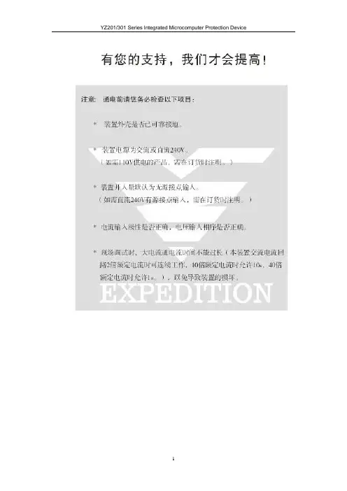
Our Improvement upon Your SupportNote: Please make sure to examine the following items before power-on:* Reliable grounding of device enclosure.* Power supply of the device is AC or DC and 240V.(If 110V power supply is required, it shall be indicated during ordering.)* Default of device input is passive contact input.(If active contact input of DC 240V is required, it shall be indicated during ordering.)* Default of the device is without anti-bouncer function(If product with anti-trip function is required, it shall be indicated during ordering.)* Correct polarity of current input as well as correct phase sequence of voltage input* During on-site debugging, power-on time of high current shall not be too long (For this device, continuous running is available when current in the AC current circuit is twice of the rated current, 10s running is allowable under ten times of the rated current and 1s running is allowable under 40 times of the rated current.), so as to avoid unnecessary damage.1概述YZ201/301系列综合微机保护装置是采用计算机技术、电力自动化技术、通信技术等多种高新技术的新型电器产品。
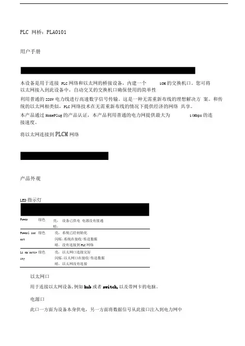
PLC 网桥:PLA0101用户手册本设备是用于连接PLC网络和以太网的桥接设备,内建一个10M的交换机口。
您可将以太网接入到此设备中,自动交叉的交换机口确保使用的简单性利用普通的220V电力线进行高速数字信号传输。
这是一种无需重新布线的理想解决方案。
和传统的以太网相类似,PLC网络技术在无需重新布线的情况下提供经济的网络共享。
本产品通过HomePlug的产品认证,本产品利用普通的电力网提供最大为14Mbps的连接速度。
将以太网连接到PLCM网络产品外观LED指示灯Power 绿色亮:暗:设备已供电电源没有接通Powerl ine 绿色亮:系统已经初始化Act 闪烁:系统在接收/传送数据暗:没有连接到PLC网络Li nk/Activ 绿色亮:以太网口连接完好ity 闪烁:以太网口在接收/传送数据暗:以太网没有连接以太网口用于连接以太网设备,例如hub或者switch,以及带网卡的电脑。
电源口此口一方面为设备本身供电,另一方面将数据信号从此接口注入到电力网中将设备平稳的放置于工作场所将电源线插入设备的电源口1.使用标准的RJ-45以太网线从设备的交换口连接服务器、工作站或者PC机2.如果需要可以将别的hub/switch使用标准的RJ-45以太网线连接到设备的交换口.用户无需用特殊的交叉线做级连。
3.确保所有的缆线安装正确后,将电源线接入到电源插座中。
注意事项1.介于设备和PC/hub/Switch 中的网线不得超过100米。
2.确保缆线的正确性.在10Mbps时,3/4/5类线均可用以连接•为确保工作于100Mbps,你必须使用5或更好的线.Q:什么是PLC网络?A: Powerline network uses a home's existing electrical wiring and jacks, along with special adapters and software, to connect multiple PCs for PC peripheral shari ng, data sharing and Internet sharing.Q:为什么我需要PLC网络?A: Both powerli ne and wireless are for no-n ew-wire home n etwork ing. Powerl ine network can deliver reliable and long range transmission of home streaming Audio/Video data without the limitation of RF characteristics. Also based on HomePlug 500 home field test, the performanee is 50% to 150% better than802.11b.Q:在PLC网络中我需要些什么设备?unique multi Ether net port desig n, it makes your applicati on more flexible.Q:家用电器会对PLC网络有影响吗?A: No. The HomePlug sta ndard has great sig nal process ing algorithm to overcomes the noise, but only the transmission speed will get a little bit lower .Q:我能将PLC设备的电源线接到UPS中吗?A: You will get the b est performanee when plugged directly into the wall outlet. It ' s better not to be plugged into UPS's or power strips due to the insertion loss thoughit still can work.。

L301系列静压液位计安装使用说明书solution中国服务中心L301系列静压液位计安装使用说明书L301系列静压液位计采用美国SOLUTION(斯卢森)公司提供的陶瓷电容式传感器,是我公司为适应中国市场需求,而自行开发和生产的新一代液位测量仪表,该仪表具有性能可靠,安装简单和使用方便的特点,该系列有六种型号静压液位计:L301-1型为沉入缆式结构;L301-2型为沉入杆式结构;L301-3型为直装螺纹旋入式结构;L301-4型为直装法兰式结构,四者均具隔爆和本安型。
L301-5和L301-6接触介质部分材料为PTFE或哈氏合金,适用于强酸、强碱等强腐蚀介质测量,具本安防爆型。
L301-5型为沉入缆式结构;L301-6型为沉入杆式结构。
工作原理L301系列静压液位计通过压力传感器实现液位测量。
压力传感器探入或接触被测液体,受到一定的静压(P)。
此压力(P,MPa)与液体高度(h,m)的关系列为P=10ֿ³ρgh。
式中为被测液体密度(g/cm³),g为当地的重力和速度(m/s²)。
对于一定的被测介质和地点,ρ和g为常数,压力和液位高度成正比。
如此,通过压力传感器实现了液位测量。
技术数据防爆标志:隔爆型dllCT6〔不含乙炔〕(L301-1﹑L301-2﹑L301-3﹑L301-4﹑)本安型:ibllCT4本安型关联设备:KAS901安全限能器或LB803S型安全栅满度测量范围:L301-11~100M(隔爆型1~20m)L301-20.5~4m;L301-3、L301-42~100mL301-51~5m;L301-60.5~3m精度等级:0.2级,0.5级长期稳定性:优于0.1%/年环境温度:-20~70℃介质温度:-20~+60℃(L301-1、L301-5)-20~+80℃(L301-2、L301-6)-40~+130℃(L301-3、L301-4)变送器防护等级:IP65传感器防护等级:IP68电源电压:普通型13-30.5V DC;隔爆型12.5~30V DC本安型12.6~24V DC变送器输出:4~20Ma贮存环境温度:L301-1、L301-5-20~+60℃L301-2、L301-3、L301-4、L301-6-40~+85℃贮存环境湿度:﹤90%RH变送器外壳材料:压铸铝合金测量膜片密封外壳L301-1、L301-296%氧化铝陶瓷氟橡胶等1Cr18Ni9TiL301-3、L301-4316或哈氏合金等电子束焊1Cr18Ni9TiL301-5、L301-696%氧化铝陶瓷PTFE PTFE传感器材料LL301-1L301-2L301-2L301-2过程连接为GI1/2“过程连接为法兰过程连接为GI1/2〞过程连接为法兰1.传感器其它与左图所示同 1.传感器其它与左图所示同2.导气电缆 2.加长杆(Icr8NigTi无缝管)3.过程连接 3.过程连接4.变送器 4.变送器L301-4L301-31.隔离膜片 1.隔离膜片2.法兰 2.外螺纹3.电缆引入口 3.电缆引入口4.变送器 4.变送器安装时切勿碰损波纹板测量膜片L301-5L301-5L301-6L301-6传感器外壳为哈氏合金传感器外壳为PTFE传感器外壳为哈氏合金传感器外壳这PTFEPTFE配重Q=128 1.变送器 2.过程连接 3.法兰GB9119.6-88DNG5哈氏合金配重Q=70 4.加长杆 5.传感器 6.测量膜片1.电缆2.传感器具3.测量膜片4.配重L.加长杆长度L.电缆长度防爆型与防腐型液位计安装使用注意事项(一)隔爆型1.在爆炸危险区域开启液位变送器外壳时,必须切断仪表电源.2.把盖旋紧后务必将盖上的紧定螺纹旋紧.(二)本安型1.液位计应单独安装,尽量远离大功率设备,以避免电磁感应和静电感应.2.本安电路的外部导线应单独布置,不允许与高压电缆一起敷设.3.液位计到安全栅的连接导线应尽量缩短,禁止盘卷连接导线的分布电感,分布电容与液位计的等效电感,等效电容分别之和须少于安全栅规定的额定值(例如:当导线截面1mm2时,连接导线的总长度不大于1000米).4.为确保本安性能,用户不得随意更换器件,维修有困难应送本公司修理.5.变送器线路板上设有电源接线端子(端子下面有“+”“-”标记),接线后,端子的卡口外不得有裸铜线.(三)防腐型(L301-5、L301-6)L301-5、L301-6防腐型静压液位计电缆接触被测介质的材料系聚四氟乙烯.鉴于该材料比金属材料强度差、硬度低等特点,请用户在运输、拆包装和仪表安装过程中,防止仪表受到碰伤、摔损、冲击和折曲等损坏.另外,使用L301-5的用户需注意以下几点:1.切勿折曲电缆和损伤电缆表面;2.电缆和传感器、变送器之间不得拉拔;3.传感器外壳材料为PTFE的L301-5必需加配重(其材料为PTFE或哈氏合金C276),配重安装时请将传感器端部的护罩旋下,然后手持传感器将配重旋入,开始旋入时请注意将螺纹对正.4.传感器和配重一起投入介质时,请缓慢设放,切勿猛然掷入.安装方式安装方式图法兰连接螺纹连接分离式注意:L301-1、L301-5的导气电缆不可过分夹紧和折曲过锐L301-1、L301-5的安装方式有螺纹连接、法兰连接和分离式三种,法兰连接采用GB9119。
HND2001S-GK1(三相三线)HND2001T-DK1 (三相四线)大客户负荷管理系统现场终端使用说明书(Ver2.0)( 通 过 ISO9001认 证 )深圳市银骏科技有限公司目 录1技术说明 (4)1.1概述 (4)1.2标准及规范 (4)1.3技术参数 (4)1.3.1I/O配置 (4)1.3.2测量精度 (5)1.3.3费率时段 (5)1.3.4通信接口 (5)1.3.5通信性能指标 (5)1.3.6无线信号指示 (5)1.3.7显示方式 (5)1.3.8电源 (5)1.3.9备用电源 (5)1.3.10绝缘性能 (6)1.3.11工作环境 (6)1.3.12体积和重量 (6)1.3.13可靠性 (6)1.3.14其它 (6)1.4基本功能 (6)1.4.1通讯功能 (6)1.4.2保电、剔除功能 (10)1.5外形及部件名称 (10)1.6面板操作 (10)1.7终端显示 (11)1.7.1终端显示格式 (11)1.8端钮接线图 (12)1.9电池 (34)2安装须知 (35)2.1安装准备工作 (35)2.1.1安装必备工具: (35)2.1.2备用工具: (35)2.1.3安装材料 (35)3终端安装说明 (36)3.1固定终端 (36)3.2电源部分接线 (36)3.3485接线 (36)3.4辅助端脉冲输入接线 (37)3.5辅助端遥控接线、遥信接线 (37)3.6天线的安装 (37)3.7安装验证 (37)3.8注意事项 (37)3.9在安装完毕详细验证后,认真填写《终端安装工作单》 (38)4现场安装验收步骤 (39)5终端运行后的维护 (39)5.1在日常巡检中,可注意以下方面 (39)5.2当终端所带表计需要更换时要注意的问题 (39)5.3当终端所带表计需要增加时要注意的问题 (39)5.4当终端出现不可修复故障需要更换时要注意的问题 (39)5.5因终端具备远程升级功能,因此对于一般性的故障,可以通过远程升级软件来解决问题。
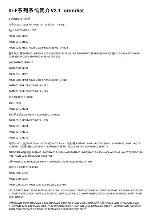
0i-F系列系统简介V3.1_orderlist3 Orderlist变化说明内容0i-MD(1包)0i-MF Type 10i-TD(1包)0i-TF Type 1Type 1A02B-0320-H532A02B-0340-H530A02B-0319-H532A02B-0339-H530 A02B-0320-H533A02B-0319-H533基本单元0槽A02B-0319-B500A02B-0338-B500A02B-0319-B500A02B-0338-B500基本单元2槽A02B-0319-B502A02B-0338-B502A02B-0319-B502A02B-0338-B502主板A02B-0319-H120A02B-0338-H101A02B-0319-H120A02B-0338-H101 A02B-0319-H121A02B-0319-H121A02B-0319-H122A02B-0319-H122A02B-0319-H123A02B-0319-H123轴卡A02B-0319-H032集成于主板A02B-0319-H031集成于主板A02B-0319-H033A02B-0319-H032A02B-0319-H034A02B-0319-H033A02B-0319-H034A02B-0319-H042A02B-0319-H043内容0i-MD(1包)0i-MF Type 10i-TD(1包)0i-TF Type 1电源0槽A02B-0319-H111A02B-0338-H110A02B-0319-H111A02B-0338-H110电源2槽A02B-0319-H112A02B-0338-H112A02B-0319-H112A02B-0338-H112FROM/SRAM存储器A02B-0319-H056A02B-0338-H056A02B-0319-H056A02B-0338-H056 A02B-0319-H057A02B-0338-H057A02B-0319-H057A02B-0338-H057铭牌A02B-0320-H190A02B-0340-H190A02B-0319-H190A02B-0339-H190电缆卡⼦A02B-0124-K001A02B-0303-K001A02B-0124-K001A02B-0303-K001 A02B-0303-K001A02B-0303-K001MDI A02B-0319-C125#M A02B-0323-C125#M A02B-0319-C125#T A02B-0323-C125#T A02B-0319-C126#M A02B-0323-C126#M A02B-0319-C126#T A02B-0323-C126#T A02B-0303-C120#M A02B-0323-C120#M A02B-0303-C120#T A02B-0323-C120#T空槽板A02B-0319-J190A02B-0338-J190A02B-0319-J190A02B-0338-J190控制单元保险A02B-0236-K100A02B-0236-K100A02B-0236-K100A02B-0236-K100电池A02B-0309-K102A02B-0323-K102A02B-0309-K102A02B-0323-K102风扇A02B-0309-K120A02B-0323-K120A02B-0309-K120A02B-0323-K120内容0i-MD(1包)0i-MF Type 10i-TD(1包)0i-TF Type 1 8.4“横置(USB)A02B-0319-H164#M A02B-0338-H144#M A02B-0319-H164#T A02B-0338-H144#T8.4“纵置(USB)A02B-0319-H165#M A02B-0338-H145#M A02B-0319-H165#T A02B-0338-H145#T8.4“横置(USB)A02B-0319-H168#M A02B-0338-H148#M A02B-0319-H168#T A02B-0338-H148#T 带触摸屏8.4“纵置(USB)A02B-0319-H169#M A02B-0338-H149#M A02B-0319-H169#T A02B-0338-H149#T 带触摸屏10.4 横置A02B-0319-H160A02B-0338-H141A02B-0319-H160A02B-0338-H14110.4 横置,A02B-0319-H161A02B-0338-H142A02B-0319-H161A02B-0338-H142触摸屏10.4 横置,A02B-0319-H162A02B-0338-H142A02B-0319-H162A02B-0338-H142触摸屏+软键内容0i-MD(1包)0i-MF Type 10i-TD(1包)0i-TF Type 1机械组数-A02B-0340-S836#1-A02B-0339-S836#1路径数-A02B-0340-S801#1A02B-0319-S801#1A02B-0339-S801#1 --A02B-0319-S801#2A02B-0339-S801#2伺服电机数-A02B-0338-J398#n-A02B-0338-J398#n 使⽤SDU电机数-A02B-0338-J388#m-A02B-0338-J388#m 选项功能A02B-0320-xxxx A02B-0340-xxxx A02B-0319-xxxx A02B-0339-xxxx控制轴数扩展A02B-0320-R689A02B-0340-R689A02B-0319-R689A02B-0339-R689软件A08B-9010-J555#ZZ12A08B-9010-J555#ZZ12光盘A08B-9012-J008#CM A08B-9012-J013#12A08B-9012-J008#CMA08B-9012-J013#12内容0i Mate-MD(3包)0i-MF Type 30i Mate-TD(3包)0i-TF Type 3 Type 3A02B-0322-H532A02B-0340-H533A02B-0321-H532A02B-0339-H533基本单元0槽A02B-0321-B500A02B-0338-B520A02B-0321-B500A02B-0338-B520主板A02B-0319-H125A02B-0338-H106A02B-0319-H125A02B-0338-H106轴卡集成于主板A02B-0319-H031集成于主板A02B-0319-H032A02B-0319-H032A02B-0319-H033A02B-0319-H033电源A02B-0319-H111集成于主板A02B-0319-H111集成于主板FROM/SRAM存储器A02B-0319-H051A02B-0338-H056*A02B-0319-H051A02B-0338-H056*铭牌A02B-0322-H190A02B-0340-H190A02B-0321-H190A02B-0339-H190电缆卡⼦A02B-0124-K001A02B-0303-K001A02B-0124-K001A02B-0303-K001 A02B-0303-K001A02B-0303-K001内容0i Mate-MD(3包)0i-MF Type 30i Mate-TD(3包)0i-TF Type 3 8.4“横置(USB)A02B-0319-H164#M A02B-0338-H144#MA02B-0319-H164#T A02B-0338-H144#T8.4“纵置(USB)A02B-0319-H165#M A02B-0338-H145#M A02B-0319-H165#T A02B-0338-H145#T8.4“横置(USB)A02B-0319-H168#M A02B-0338-H148#M A02B-0319-H168#T A02B-0338-H148#T 触摸屏8.4“纵置(USB)A02B-0319-H169#M A02B-0338-H149#M A02B-0319-H169#T A02B-0338-H149#T 触摸屏控制单元保险A02B-0236-K100A02B-0236-K100A02B-0236-K100A02B-0236-K100电池A02B-0309-K102A02B-0323-K102A02B-0309-K102A02B-0323-K102风扇A02B-0309-K120A02B-0323-K120A02B-0309-K120A02B-0323-K120内容0i Mate-MD(3包)0i-MF Type 30i Mate-TD(3包)0i-TF Type 3机械组数-A02B-0340-S836#1-A02B-0339-S836#1路径数-A02B-0340-S801#1-A02B-0339-S801#1伺服电机数-A02B-0338-J398#n-A02B-0338-J398#n 使⽤SDU电机数-A02B-0338-J388#m-A02B-0338-J388#m 选项功能A02B-0322-xxxx A02B-0340-xxxx A02B-0321-xxxx A02B-0339-xxxx控制轴数扩展A02B-0320-R689-A02B-0319-R689A02B-0339-R689同时控制轴扩展A02B-0322-J803-A02B-0321-J803-软件A08B-9010-J555#ZZ12A08B-9010-J555#ZZ12光盘A08B-9012-J008#CM A08B-9012-J013#12A08B-9012-J008#CMA08B-9012-J013#12内容0i Mate-MD(5包)0i-MF Type 50i Mate-TD(5包)0i-TF Type 5 Type 5A02B-0322-H535A02B-0340-H535A02B-0321-H535A02B-0339-H535基本单元0槽A02B-0321-B530A02B-0338-B520A02B-0321-B530A02B-0338-B520主板(模拟)A02B-0322-H136A02B-0338-H107A02B-0322-H136A02B-0338-H107主板(串⾏)A02B-0322-H137A02B-0338-H108A02B-0322-H137A02B-0338-H108电源集成于主板集成于主板集成于主板集成于主板轴卡集成于主板集成于主板集成于主板集成于主板FROM/SRAM存A02B-0319-H061A02B-0338-H056*A02B-0319-H061A02B-0338-H056*储器铭牌A02B-0322-H190A02B-0340-H190A02B-0321-H190A02B-0339-H190电缆卡⼦A02B-0303-K001A02B-0303-K001A02B-0303-K001A02B-0303-K001内容0i Mate-MD(5包)0i-MF Type 50i Mate-TD(5包)0i-TF Type 5 8.4“横置(USB)A02B-0319-H174#M A02B-0338-H144#M A02B-0319-H174#T A02B-0338-H144#T8.4“纵置(USB)A02B-0319-H175#M A02B-0338-H145#M A02B-0319-H175#T A02B-0338-H145#T8.4“横置(USB)A02B-0319-H178#M A02B-0338-H148#M A02B-0319-H178#T A02B-0338-H148#T 触摸屏8.4“纵置(USB)A02B-0319-H179#M A02B-0338-H149#M A02B-0319-H179#T A02B-0338-H149#T 触摸屏控制单元保险A02B-0236-K100A02B-0236-K100A02B-0236-K100A02B-0236-K100电池A02B-0323-K102A02B-0323-K102A02B-0323-K102A02B-0323-K102电缆卡⼦A02B-0303-K001A02B-0303-K001A02B-0303-K001A02B-0303-K001内容0i Mate-MD(5包)0i-MF Type 50i Mate-TD(5包)0i-TF Type 5机械组数-A02B-0340-S836#1-A02B-0339-S836#1路径数-A02B-0340-S801#1-A02B-0339-S801#1伺服电机数A02B-0322-R419#n A02B-0338-J398#n A02B-0321-R419#n A02B-0338-J398#n 使⽤SDU电机数-A02B-0338-J388#m-A02B-0338-J388#m 选项功能A02B-0322-xxxx A02B-0340-xxxx A02B-0321-xxxx A02B-0339-xxxx控制轴数扩展A02B-0320-R689-A02B-0319-R689A02B-0339-R689同时控制轴扩展A02B-0322-J803-A02B-0321-J803-软件A08B-9010-J555#ZZ12A08B-9010-J555#ZZ12光盘A08B-9012-J008#CM A08B-9012-J013#12A08B-9012-J008#CMA08B-9012-J013#12FROM/SRAM存储器的选择需根据Option Assembly计算得到,当存在以下功能时需使⽤128M/2M:Designation of Control paths: 2paths (S801#2)Function for loader control (R417)Tool management function (S830, S831, S833)C Language Executor additional SRAM (J736, S827)Quick program restart (R630)Quick program restart II(R414)Peripheral axis control (R725)FANUC PICTURE function (S879)Nonvolatile PMC data table area expansion (40KB)(S967#40K)Nonvolatile PMC extra relay function (S984#10K)Robot connection function (R683)Multi-path PMC function (3 paths) (R855#3)MANUAL GUIDE i(S790)MANUAL GUIDE 0i (S772)IO类型IO单元0i-D系列IO Link0i-F系列IO Link i电⽓柜⽤IO单元(0i⽤IO单元)I/O unit for 0i A02B-0309-C001A02B-0319-C001操作⾯板⽤IO模块I/O module for operator's panel A1A03B-0815-K200A03B-0824-K200 I/O module for operator's panelB1A03B-0815-K202A03B-0824-K202 I/O module for power magnetics cabinet B2A03B-0815-K203A03B-0824-K203分线盘⽤IO模块I/O module for connector panel B1A03B-0815-C001A03B-0824-C001 I/O module for connector panel EAA03B-0815-C002A03B-0824-C002 I/O module for connector panel EB A03B-0815-C003A03B-0824-C003 I/O module for connector panel EC A03B-0815-C004A03B-0824-C004 I/O module for connector panel ED A03B-0815-C005A03B-0824-C005 I/O module for connector panel Cablefor module connectionA03B-0815-K100A03B-0815-K100 I/O module type-2 for connector panel B1A03B-0815-C040A03B-0824-C040 I/O module type-2 for connector panel B2A03B-0815-C041A03B-0824-C041 I/O module type-2 for connector panel E1A03B-0815-C042A03B-0824-C042 Cable of I/O module type-2 for connectorpanel for module connectionA03B-0815-K102A03B-0815-K102端⼦转换适配器TERMINAL CONVERSION ADAPTER TA1A03B-0824-K151 TERMINAL CONVERSION ADAPTERTA2A03B-0824-K152 TERMINAL CONVERSION ADAPTER TA3A03B-0824-K153IO类型IO单元0i-D系列IO Link0i-F系列IO Link i端⼦型IO模块Terminal Type I/O module Basic Module A03B-0823-C001A03B-0823-C011 Terminal Type I/O module Extension module A A03B-0823-C002A03B-0823-C012 Terminal Type I/O module Extension module B A03B-0823-C003A03B-0823-C013 Terminal Type I/O module Extension module C A03B-0823-C004A03B-0823-C014 Terminal Type I/O module Extension module D A03B-0823-C005A03B-0823-C015 Terminal Type I/O module Extension module E A03B-0823-C006A03B-0823-C016 Terminal Type I/O module Extension cable A A03B-0823-K100A03B-0823-K100操作⾯板Machine operator's panel Main panel A(Symbolic & English key)A02B-0319-C242Machine operator's panel Main panel B(Symbolic & English key)A02B-0319-C243A02B-0323-C231 Safety Machine operator's panel A02B-0323-C234 Safety Machine operator's panel type B A02B-0323-C235光缆适配器Optical I/O link adapter A13B-0154-B001A13B-0154-B101 IO UNITMODELAIO UNIT MODEL A A03B-0819-Jxxx A03B-0826-JxxxSDU名称0i-D系列0i-F系列Position detector I/F unit A02B-0303-C205A02B-0323-C205Separate Detector I/F Unit Additional 4A02B-0236-C204A02B-0323-C204 AxesAnalog input separate detector I/F unitA06B-6061-C201A06B-6061-C202 Basic 4 axesαi-B放⼤器3.3放⼤器对⽐项αi放⼤器αi-B放⼤器αiPS电源模块A06B-6140-HxxxA06B-6150-HxxxA06B-6200-HxxxA06B-6250-HxxxαiSV伺服模块A06B-6117-HxxxA06B-6127-HxxxA06B-6240-HxxxA06B-6290-HxxxαiSP主轴模块A06B-6141-Hxxx#H580A06B-6142-Hxxx#H580A06B-6151-Hxxx#H580A06B-6152-Hxxx#H580A06B-6220-Hxxx#H600A06B-6270-Hxxx#H600交流电抗器/浪涌接收器原型号新型号放⼤器⽤插头A06B-6071-K203A06B-6200-K200电池单元⼀致保险A06B-6077-K250A06B-6073-K250A06B-6073-K250主轴电缆A02B-0236-K845主轴信号与伺服共⽤FSSB光缆(省配线,传输速度快)加⼯性能提升机械效率提升易⽤性提升z 伺服HRV + 控制z FSSB⾼速刚性攻丝z 风扇电机前端维护z 故障诊断z 主轴电机智能加减速z 安全扭矩关断功能(STO)放⼤器对⽐项现有βiSVSP放⼤器βiSVSP-B放⼤器订货规格号A06B-6164-Hxxx#H580A06B-6320-Hxxx风扇单元*-7.5/11/15:A06B-6134-K001*-18:A06B-6134-K006内置冷却风扇单元⽆需单独订购电池单元⼀致放⼤器插头A06B-6134-K201A06B-6200-K200电抗器/浪涌接收器A81L-0001-0155/0156/0157A06B-6200-K141A81L-0001-0184/0185/0186A06B-6200-K141主轴连接A02B-0236-K845主轴信号与伺服共⽤FSSB光缆(省配线,传输速度快)伺服扩展通过右下⾓端⼦扩展SV/SP直接使⽤短路棒扩展附:具体细节变化请参考技术报告TMS14-049E βiSV-B单体放⼤器3.3放⼤器对⽐项现有βiSV单体放⼤器βiSV-B单体放⼤器订货规格号A06B-6130-Hxxx(单轴)A06B-6131-Hxxx(单轴HV)A06B-6136-Hxxx(双轴)A06B-6160-Hxxx(单轴)A06B-6161-Hxxx(单轴HV)A06B-6166-Hxxx(双轴)(A06B-6166-H201#A)风扇单元/电池单元⼀致放⼤器插头⼀致线性滤波器/放电电阻⼀致I/O Link I/F规格A06B-6132-Hxxx(单轴)A06B-6133-Hxxx(单轴HV)A06B-6162-Hxxx(单轴)A06B-6163-Hxxx(单轴HV)附:IO Link轴注意使⽤⽼电机。
三淼管道机器人使用说明书1. 简介三淼管道机器人是一种专门用于检测和维护管道系统的自动化设备。
它具有高精度、高效率和安全可靠的特点,可以在各种复杂环境下进行工作。
本使用说明书将详细介绍三淼管道机器人的组成部分、使用方法以及注意事项。
2. 组成部分三淼管道机器人由以下几个主要部分组成:2.1 主控制系统主控制系统是整个机器人的核心,它负责控制和监控机器人的运行状态。
主控制系统具有用户友好的界面,可以通过该界面对机器人进行操作和监测。
2.2 传感器装置传感器装置是用于采集管道内部数据的设备,包括摄像头、温度传感器、压力传感器等。
这些传感器能够实时获取管道内部的信息,并通过主控制系统进行处理和分析。
2.3 运动系统运动系统是用于驱动机器人在管道中移动的部件,包括电动轮、履带等。
运动系统能够根据指令精确地控制机器人的移动方向和速度。
2.4 电源系统电源系统为机器人提供稳定的电力支持,包括电池组、充电器等。
机器人的工作时间和续航能力取决于电源系统的性能。
3. 使用方法3.1 准备工作在使用三淼管道机器人之前,需要进行一些准备工作:•确保机器人已经充满电,并正确连接到主控制系统。
•检查传感器装置是否正常工作,确保各个传感器能够正常采集数据。
•检查运动系统是否正常,确保机器人能够在管道中自由移动。
3.2 运行机器人将三淼管道机器人放入待检测的管道中,通过主控制系统对其进行操作:1.打开主控制系统,并登录账户。
2.在主界面上选择要执行的任务类型,例如巡检、清洗或维修。
3.设置相关参数,如巡检速度、清洗强度等。
4.点击开始按钮,机器人将开始执行任务。
3.3 监测和分析数据在机器人执行任务期间,可以随时通过主控制系统监测和分析采集到的数据:•实时查看管道内部的图像和视频。
•分析温度和压力数据,判断管道是否存在异常情况。
•根据数据分析结果,及时采取相应的措施。
3.4 完成任务当机器人完成任务后,需要进行以下操作:1.停止机器人的运行。

飞锯/追剪专用控制器EP09Versoin1.0使用前请先阅读本手册目录目录目录................................................ I一、飞锯/追剪的运动特点 (1)二、系统框架 (2)三、系统参数 (3)1.厂家参数设定 (3)2.用户参数设定 (3)3.设定后生成的数据比较 (4)四、控制模式 (5)1.手动模式 (5)2.自动模式 (5)五、控制器端子说明 (6)六、参数使用方法 (7)七、EP09控制器尺寸 (8)八、电路图 (9)一、飞锯/追剪的运动特点在设定的同步区牵引剪切部件的速度和送料速度一致,在同步区完成剪切运动,而不同的切割长度则通过调节非同步区速度来适应。
该飞锯/追剪系统由测量轮,牵引电机,剪切电磁阀和运动控制器完成追剪运动。
测量轮负责平稳无打滑测量物料的长度和速度,牵引电机由伺服系统驱动,运动控制器根据设定的切断长度发出对应的脉冲给伺服控制系统使剪切部件跟踪材料同步运动;剪切/飞锯电磁阀在剪切部件与材料同步时完成剪切/飞锯。
康尼斯追剪控制系统应用此处的参数设定分为两个部分:1. 厂家参数设定2. 用户参数设定3. 设定后生成的数据比较本系统工作方式分为以下三种:当系统电源闭合的所有条件满足后,系统才能启动,启动后系统应进入手动模式。
而通常在生产过程使用自动方式。
1. 手动模式系统正常运行所需的条件具备以后,系统通电后进入手动模式,而实际生产使用的是自动模式,在手动模式下,当按下正向点动按钮,刀架向正方向走,当按下反向点动按钮,刀架向反方向走,按下回零按钮,刀架回零点。
2. 自动模式这是为正常生产设置的操作方式,根据设定的切断长度,刀架自动与材料移动并按照设定长度对材料进行切断,然后刀架反回原点位置。
切刀的速度由设定长度和材料速度自动计算决定。
在指定的环境条件具备后,按下“自动模式”按钮,系统就能进入自动操作方式。
注意:在自动模式下,即使材料处于停止状态,也有可能因某种偶然因素引起测量轮转动而导致刀架移动。
Product description• Compact dimensions for luminaire installation• For up to 20 DSI or DALI devices (max. 10 per output channel)• DALI IN input• 2 DALI/DSI output channels with adjustable offset from channel 2 to channel 1• 1 relais output• Sensor input for up to 4 basicDIM DGC sensors 5DPI 14• 2 switch inputs for on/off switching and dimming• Individual adjustment of the parameters withbasicDIM DGC Programmer orsoftware masterCONFIGURATOR• 5 years guarantee (conditions at )ÈWiring diagrams and installation examples, page 10basicDIM DGC Compact control moduleTechnical dataRated supply voltage220 – 240 V Mains frequency50 / 60 Hz Power 2.5 WStand-by power0.5 WCurrent draw, input (DALI bus) 2 mAMax. number of switched drivers2Max. Inrush current of the load (peak / duration)55 A / 400μs Typ. number of switching cycles150,000Max. resistive load500 WMax. inductive / capacitive load200 VA Dimming range 1 – 100 %tc70 °C Operating temperature0 ... +60 °C Storage temperature-25 ... +70 °C Type of protection IP20 Dimensions L x W x H159 x 30 x 21 mm basicDIM DGCCompact control moduleOrdering dataType Article number Mounting Packaging carton Weight per pc. basicDIM DGC28000920Luminaire installation10 pc(s).0.06 kgSpecific technical dataType Inputs Outputs CH2 as Link LineDimming switch Max. cable length at1.5 mm²Max. basicDIMDGC sensorsMax. sensor linelength at 0.2 –1.5 mm²Digital controlline DALI/DSIControl output per physicaloutput (devices)Maximum cablelength at 1.5mm²Voltage DC Maximum cablelength at 1.5mm²Number ofcombinablemodulesbasicDIM DGC double100 m410 m210100 m13 V100 m10 1 See data sheet 8.2 Switching cycles.Product description• Light measurement and motion detection• Up to 4 basicDIM DGC sensors on one basicDIM DGC• Can be remote controlled• Light measurement and motion detection can be deactivated • Individual adjustment of the parameters with basicDIM DGC Programmer or software masterCONFIGURATOR• Power supply via basicDIM DGCTechnical dataØ of detection range, mounted at a height of 2.5 m 4.5 mSwivel design noDetection angle84°Light measurement at the sensor head 110 – 650 lxInfra-red control range 5 mMax. mounting height 5 mOperating temperature0 ... +50 °CStorage temperature-25 ... +55 °CType of protection IP20basicDIM DGC Sensor 5DPI 14f44,4Ø13,916,41,9312,8219,7Ordering dataType Article numberPackaging,Weight per pc.1The measured value at the sensor head corresponds to approx. 15 to 2,000 lux on the surface measured.Product description• Mounting frame for attaching all 5DP 14f sensor directly to the luminaire housing• Shutter for preventing movement detection in one direction•Glow wire test with 750 °C according to EN 61347-15DPI 14f Mounting KitOrdering dataProduct description• Mounting frame for wired 5DP 14f sensors allowing direct mounting to the ceiling• Easy …click in“ installation of the sensor• IP20• Casing: plastic, white• UV stabilized plastic• DALI MSensor 5DPI 14 is powered via DALI circuit, basicDIM DGC Sensor 5DPI 14f powered via control unit• Optional shutter for reduction of movement detection area allowing to decrease the movement detection area from 360° to 240°• Mounting kit with screws and decorative plugs• 0.5 mm wiring for the sensor• Two 3 x 1.5 mm² clamps with cable management (2 entry points on oppsite sides)• Glow wire test with 750 °C according to EN 61347-1ACU Sensor Housing 14rs IP20Ordering databasicDIM DGC Sensor 5DPI 14rc65,45,5Ø46,75Ø58128Ordering dataTypeArticle number Packaging, Weight per pc.Product description• Light measurement and motion detection• Up to 4 basicDIM DGC sensors on one basicDIM DGC • Can be remote controlled• Light measurement and motion detection can be deactivated • Individual adjustment of the parameters with basicDIM DGC Programmer or software masterCONFIGURATOR • Power supply via basicDIM DGC Technical dataØ of detection range, mounted at a height of 2.5 m 4.5 m Swivel design no Detection angle84°Light measurement at the sensor head 110 – 650 lx Infra-red control range 5 m Max. mounting height 5 m Operating temperature 0 ... +50 °CStorage temperature -25 ... +55 °C Type of protectionIP201The measured value at the sensor head corresponds to approx. 15 to 2,000 lux on thesurface measured.Product description• Optional infra-red programming unit for basicDIM DGC • Setting of predefined discrete parameter values • Programmable functions such as light level, time delay,P.I.R., bright-out, power upbasicDIM DGC ProgrammerOrdering dataREMOTECONTROL IR6A C C E S -S O R I E SOrdering dataProduct description• Optional infra-red remote control • Switching on and off (On/Off button)• Dimming (Up/Down button)• Activation of automatic lighting control •Setting the threshold control point (Set button)Strain-relief setOrdering dataProduct description• Strain relief for up to 3 cables suitable for cable with diameter from 2.5 up to 9 mm • A: 2.5 – 5 mm diameter • B: 5 – 9 mm diameter • C: 5 – 9 mm diameter• Optional strain-relief set for independent applications • Transforms the unit into a full Class II compatible unit (e.g. for ceiling installation)• One set includes 2 pieces strain-reliefs • 5 years guarantee1. StandardsEN 55015EN 61000-3-2EN 61347-1EN 61347-2-11EN 61547EN 62386-101EN 60598-11.1 DALI standardThe basicDIM DGC is designed to control control gear with DALI standardIEC 60929 (DALI V0) and IEC 62386 (DALI V1).1.2 Glow-wire testaccording to EN 61347-1 passed.2. CommonThe basic DIM DGC provides the basis for an easy-to-use and cost-effective lighting system with motion detection.When the sensor detects movement it triggers a individual adjustable motion detection profile in the control unit.As the amount of natural ambient light changes the illuminance from the artificial lighting system is adjusted.The connected luminaires can be switched on and off via momentary-action switch or remote control possible.The DALI IN interface allows integration of the basicDIM DGC module also into a comfortDIM system.The basicDIM DGC module has 5 preprogrammed profiles which can be selected using the basicDIM DGC Programmer.The profiles can be adjusted to your application via the masterCONFIGURATOR (≥ V2.12) software.If the basicDIM DGC module is used in the basic application, the CH2 can be used as control channel for controlling subordinate basicDIM DGC modules (basic connection), so that the controlling and the subordinate basicDIM DGC modules can be programmed and allocated to groups using the masterCONFIGURATOR software. Every single basicDIM DGC module can be allocated to a group and respond to the presence of up to 5 groups (for more detailed information please refer to the masterCONFIGURATOR documentation).3. Interfaces / communication3.1 DALI INThe DALI IN interface allows integration of the basicDIM DGC module alsointo a comfortDIM or other BMS systems.However, not all DALI commands are supported. The DALI commandssupported are listed in the operating instructions.By using the DGC in basic configuration (additional DGC‘sconnected to CH2) DALI IN interface will be deactivated.3.2 DALI/DSI output channels CH1 - CH2The output channels can be set to DSI or DALI (default) using the basicDIMDGC Programmer or the masterCONFIGURATOR software.After mains failure the basicDIM DGC will set new the followingparameters to CH1/CH2:POWER ON LEVELSYSTEM FAILURE LEVELFADE TIMEMIN LEVELMAX LEVELFor more detailed information please refer to the manual.4. Installation• basicDIM DGC can be operated without sensor.The motion detection must be disabled via masterCONFIGURATOR or with unique connecting a sensor and basicDIM DGC Programmer.• DSI/DALI is not SELV. The installation instructions for mains voltage therefore apply.• The maximum cable length between the external switch and basicDIM DGC is 100 m.• The maximum cable length between the sensor and basicDIM DGC is 10 m.• A synchronous operation of DALI and DSI ballasts at the same control gear is not possible.• The output channels (for a cable cross-section of 1.5 mm2) must not be exceeded 100 m.• If CH2 is used as link line, the maximum cable length must not exceed 100 m (at 1.5 mm²).• If a basicDIM DGC is connected to CH2, DALI IN is disabled and CH2 is used as Link-Line (neighbourhood function).No control commands are transmitted via CH2, to reactivate DALI IN see basicDIM DGC manual.• Any number of push to make switches may be connected in parallel to the inputs.• Do not connect standard switches to the input.• Please ensure that the detection range of the sensor lies in the lighting area of the controlled luminaires.• Heaters, fans, printers and copiers located in the detection zone may cause incorrect presence detection.• To avoid false readings, the sensor should be installed so there is no direct light from the lamp in the detection zone.• Sensor wires must be routed separately from the lamp wires andmains cables otherwise the lighting control system may malfunction.If separate routing is not possible (for reasons of space) shieldedlamp wires and mains cables must be used.• Avoid direct illumination of the light source on the sensor includinghousing.3.3 SwitchbasicDIM DGC has two inputs (T1 and T2) for two external switches. Any number of switches can be connected in parallel to the inputs(parallel connection of T1 and T2 possible).Short press (< 500 ms):ON/OFFLong press (> 500 ms):Dim up/downA change in the light value deactivates lighting regulation only temporarily. As soon as the luminaire has beenautomatically switched on again (motion detection) or manually switched off and on again, regulation isactivated again.2 x short press:The overwritten setpoint light value is stored (luminaire acknowledges by flashing twice)Function is lockable via the DSI programmerDifferent output channels are controlled, depending on the profile selected.4.1 Wiring diagram basicDIM DGC DALIN L DA DA* must be the same phase as for LRelais in standbyN L L’DA DAmax. 64 DGC* must be the same phase as for LWiring diagram basicDIM DGC for Inteligent LuminaireNL DA DAmax. 64 DGCNL4.2 Wiring diagram basicDIM DGC with DALI PS1(2)Use only in combination with DALI Repeater (86458401) and one of the following DALI supplies:DALI PS1 (24034323), 200 mA, max. 100 additional devices DALI PS2 (28000876), 240 mA, max. 120 additional devices This combination can be used on CH1 and CH2.SensorD1D2D1D2D1D2C0C1B0B1A1A24.3 Wiring and mounting ACU Sensor Housing 14rs IP20wire preparation:4.4 Wiring type and cross-sections for basicDIM DGC For wiring use solid wire from 0.5 to 1.5 mm².wire preparation:4.5 Wiring type and cross section for sensor rc versionFor wiring use stranded wire with ferrules or solid wire from 0.2 to 1.5 mm².���� – ��� mm² solid or 4.6 Wiring type and cross section for sensor f versionFor wiring use stranded wire with ferrules from 0.2 to 0.5 mm² or solid wire from 0.14 to 0.5 mm².4.7 Mounting variants luminaire installation sensor Size of the sheet: 0.8 – 1.8 mmø14,1+0,21,5 – 2,5Size of the sheet: 0.8 – 3.0 mmSize of the sheet: 0.6 – 0.8 mm3,2 0 -0,15ø1,8 +0,1 020 +0,1 -0,14+0,2 02,2+0,219,1-0,24.8 Mounting in luminaire housing with Mounting Kit:Size of the sheet: 0.8 – 2.0 mmDimension drawing for neededmounting opening4.9 Mounting Kit mounting4.10 Mounting Kit Shutter Area which is masked by the shutter.4.11 Mounting in class II luminaireThe Sensor provides basic insulation as required by IEC 62386-101 and defined in IEC 61347-1.If the sensor is built into a class II luminaire which has to provide double or reinforced insulation it has to be considered that the Sensor is not a class II device. Still the Sensor can be used for such projects as the front of the sensor is tested to fulfill the class II requirements for double or reinforced insulation.Class II5. basicDIM DGC sensor functions5.2 Presence / motion detection5.1 Light level recognition area* The recommended maximum room height for officeapplications is 3 m and for corridor applications for example 4 m. Up to 2 m mounting height presence is detected andover 2 m motion is detected.Calculation of the diameter (light area):x1 = tan(a x1) × h x2 = tan(a x2) × h y = tan(a y ) × hCalculation of the diameter (motion area):d = 2 × tan(0,5 × a ) × hh *x1x2y d 1.7 m1.3 m 0.7 m 1.0 m 3.0 m2.0 m 1.6 m 0.8 m 1.2 m3.6 m 2.3 m 1.8 m 0.9 m 1.3 m4.1 m 2.5 m 2.0 m 1.0 m 1.4 m 4.5 m 2.7 m 2.1 m 1.1 m 1.6 m 4.9 m 3.0 m 2.3 m 1.2 m 1.7 m5.4 m 3.5 m 2.7 m 1.4 m 2.0 m6.3 m 4.0 m3.1 m1.6 m2.3 m7.2 mExample for light and motion detection area at height of 1.7 m:6. Functions6.1 RelaisThe relay can be used in four different operating modes:• Reduction of standby losses (standby wiring example)• Independent output channel for switching non-dimmable luminaires (DALI wiring example)Depending on the profile used, the relay will respond differently. For the 5 main profiles, the two relay profiles used are Standby and OnlyOFF. The masterCONFIGURATOR software allows to enable or disable the relay profiles as well.Depending on the profile used, different operating modes arepreprogrammed for the presence detector. These can be changed using thebasicDIM DGC Programmer or the masterCONFIGURATOR software.6.2 Run-on timeRun-on time of the presence detector, run-on time starts when no presence is detected.The run-on time may vary depending on the profile used.You can choose whether you want the basicDIM DGC module to switch off the light completely or to dim it down to the absence value after the run-on time.It can also be changed using the basicDIM DGC Programmer or the masterCONFIGURATOR software.Absence valueSwitch-off delayThe absence value (light level) and the switch-off delay (the period for which the level is maintained) differ depending on the profile used; theseparameters may be changed using the basicDIM DGC Programmer or themasterCONFIGURATOR software.6.3 OffsetDepending on the profile used, a negative offset may be enabled between CH2 and CH1. Using the basicDIM DGC Programmer and themasterCONFIGURATOR software, this parameter may be changed (also positive offset possible).6.4 Manual-off delayIf the light is switched off manually via momentary-action switch or remote control, the presence detector is disabled. After a period of delay without any presence detected, the presence detector is enabled again. If the sensor detects presence during the “Manual Off” delay, the delay time will start all over again. It can only be changed by using the masterCONFIGURATOR software.6.5 Lighting controlLighting control is started via the Auto key of the basicDIM Programmer or REMOTECONTROL IR6.If the basicDIM DGC module has been switched on via the ON key, lighting control is disabled.If you want to use lighting control, you need to start the DGC module via the Auto key.Lighting control can also be disabled using the masterCONFIGURATOR software.6.6 Set target valueThe light level can be set via following options: • REMOTECONTROL IR6 (press the key for > 3 s)• basicDIM DGC Programmer (press the key for > 3 s)•masterCONFIGURATOR software • external momentary-action switch: By briefly pressing the momentary-action switch twice the currently measured light level is saved as new target value.(Depending on the profile used, this function is enabled or disabled, but it can be changed using the basicDIM DGC Programmer or the masterCONFIGURATOR software)6.7 Bright-outIf the nominal illuminance level (e.g. 500 lx) is exceeded for 10 minutes at over 150 % (e.g. 750 lx), the light is switched off, even if presence is detected.The light is switched on again as soon as the measured light level falls below the target value.Depending on the profile used, this function is either enabled or disabled and can be changed using the basicDIM DGC Programmer orthe masterCONFIGURATOR software.The bright-out status can be indicated on the sensor by a slowly flashing green status LED.By default this function is disabled, but it can be enabled using the masterCONFIGURATOR software.Light control incl. bright-out activated for CH1. CH2 is not illuminated controlled.6.8 Neighbourhood functionDepending on the profile used, the basicDIM DGC can respond to presence detected in other groups.These functions can be changed using the basicDIM DGC Programmer or the masterCONFIGURATOR software.6.9 Momentary-action switch inputs6.10 Basic functions 6.12 Behaviour after return of powerThe basicDIM DGC module features two different types of starting behaviourafter mains failure.6.11 ProfilesProfile 1: Individual room Profile 2: Classroom Profile 3: Corridor Profile 4: WCProfile 5: Free-standing luminaire (default profile)Profile Test:You may use the Profile Test to check the profile you selected.All times relevant to the profile are reduced to 15 s.The Profile Test will automatically be terminated after 1 h, or by pressing the Auto key of the basicDIM DGC Programmer.The profiles can be adjusted to your needs via the masterCONFIGURATOR software or the DGC Programmer.For more detailed information please refer to the masterCONFIGURATOR documentation at .7. Brief description of profiles7.1 Individual room profile7.2 Classroom profile7.3 Corridor profile7.4 WC profile7.5 Free-standing luminaire profile (default)8. Miscellaneous8.1 DisposalAccording to the WEEE directive return old equipment at appropriate collection facilities.8.2 Additional informationAdditional technical information at → Technical Data Guarantee conditions at → ServicesLifetime declarations are informative and represent no warranty claim.No warranty if device was opened.8.3 Switching cyclesThe number of switching cycles is directly related to the level and duration of the inrush current. To increase the number of cycles either LED drivers with lower inrush current (e.g. Tridonic Industry LED drivers) oran additional external relay can be used.。
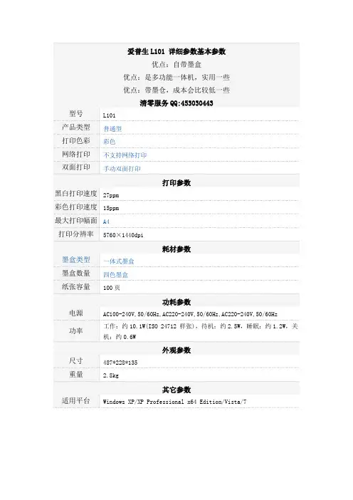
爱普生 L101 详细参数基本参数 优点:自带墨盒 优点:是多功能一体机,实用一些 优点:带墨仓,成本会比较低一些 清零服务 QQ:453030443 型号 产品类型 打印色彩 网络打印 双面打印
L101 普通型 彩色 不支持网络打印 手动双面打印
打印参数 黑白打印速度 27ppm 彩色打印速度 15ppm 最大打印幅面 A4 打印分辨率
5760×1440dpi
耗材参数 墨盒类型 墨盒数量 纸张容量
一体式墨盒 四色墨盒 100 页
功耗参数 电源 功率
AC100-240V,50/60Hz,AC220-240V,50/60Hz,AC220-240V,50/60Hz 工作:约 10.1W(ISO 24712 样张),待机:约 2.5W,睡眠:约 1.2W,关 机:约 0.6W
外观参数 尺寸 重量
487*228*135 2.8kg
其它参数 适用平台
Windows XP/XP Professional x64 Edition/Vista/7
。
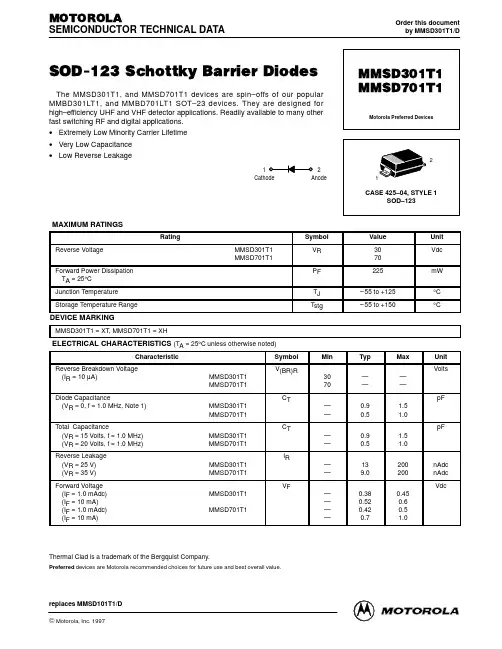
一、主要特性静态电流待机电流(检测到过放之后)过充检测精度(Topt=25℃)过充检测精度(Topt=0 到50℃)过放检测精度过放检测电压过流保护过充延迟(VDD=4.4V)过放延迟(VDD=2.2V 带有内置电容)封装典型值:4.0uA典型值:0.2uA±50mV±60mV±100mV2.0V 到3.0V,每步0.005V 0.04V 到0.32V,每步0.04V 110mS22mS(最小值)SOT23-6/6-pin二、基本描述DW01 是一款单节可充电锂电池保护集成电路,具有过充、过放、过流及短路保护功能。
IC 内部包含:三个电压检测电路、一个基准电路、一个延迟电路、一个短路保护电路和一个逻辑电路。
当充电电压逐渐增大超过过充检测电路的阈值VDET1 时,Cout Pin 的输出电压即过充检测电路的输出电压VD1 会变到低电位,也就是充电器负端的电位。
在进入过充保护状态后,当VDD 电压降低到VREL1 下方或者当电池组脱离充电器而接一个负载,且VDD 介于VDET1 与VREL1 之间时VD1 可以复位,即Cout Pin 输出变为高电位。
当放电电压低于过放检测电路的阈值VDET2 时,经过一段固定的延迟时间,Dout Pin 的输出即过放检测电路的输出VD2 会变为低电位。
这时,若给电池充电,当电池电压上升到过放检测电路的阈值电压之上时,VD2 恢复,Dout 的输出电压变为高电平。
当有过流情况出现时,内部过流检测电路会检测到,经过一段固定的延迟时间后,VD3 和Dout 变为低电平,放电回路被切断。
这时,若将电池组从负载系统中分开,VD3 会恢复使Dout 变为高电平。
当有外部短路电流时,短路保护电路会立即使Dout变为低电位,当外部短路电流消失后,Dout 会转换为高电位。
在检测到过放之后,会通过关闭一些内部电路使电源电流非常低。
IC 过充检测电路的延迟时间可以通过连接外部电容进行设置。
Vegetation Indices 16-Day L3 Global 250mMYD13Q1Short Name: MYD13Q1The MYD13Q1 images shown are samples of the MODIS/Aqua Vegetation Indices 16-Day L3 Global 250m SIN Grid product. The NDVI and EVI have been pseudo-colored to represent biomass health in using tile h22v10 from June 18 July 3, 2007.Due to their simplicity, ease of application, and widespread familiarity, vegetation indices have a wide range of usage within the user community. Some of the more common applications may include global biogeochemical and hydrologic modeling, agricultural monitoring and forecasting, land-use planning, land cover characterization, and land cover change detection.Global MODIS vegetation indices are designed to provide consistent spatial and temporal comparisons of vegetation conditions. Blue, red, and near-infrared reflectances, centered at 469-nanometers, 645-nanometers, and 858-nanometers, respectively, are used to determine the MODIS daily vegetation indices.The MODIS Normalized Difference Vegetation Index (NDVI) complements NOAA's Advanced Very High Resolution Radiometer (AVHRR) NDVI products and provides continuity for time series historical applications. MODIS also includes a new Enhanced Vegetation Index (EVI) that minimizes canopy background variations and maintains sensitivity over dense vegetation conditions. The EVI also uses the blue band to remove residual atmosphere contamination caused by smoke and sub-pixel thin cloud clouds. The MODIS NDVI and EVI products are computed from atmospherically corrected bi-directional surface reflectances that have been masked for water, clouds, heavy aerosols, and cloud shadows.Global MYD13Q1 data are provided every 16 days at 250-meter spatial resolution as a gridded level-3 product in the Sinusoidal projection. Lacking a 250m blue band, the EVI algorithm uses the 500m blue band to correct for residual atmospheric effects, with negligible spatial artifacts.Vegetation indices are used for global monitoring of vegetation conditions and are used in products displaying land cover and land cover changes. These data may be used as input for modeling global biogeochemical and hydrologic processes and global and regional climate. These data also may be used for characterizing land surface biophysical properties and processes, including primary production and land cover conversion.Version-5 MODIS Vegetation Indices products have attained Validation Stage 3.Change Points of Interest•Phased production between Terra and Aqua products for improved temporal frequency (Terra 16-day period starting Day 001, Aqua 16-day periodstarting Day 009)•Replaced NDVI_QA and EVI_QA with one VI_QA Science Data Set and added a general QA overview band called Pixel Reliability•Reduced file volume by using internal compression•More: MODIS Vegetation Index Product Series Collection 5 Change Summary (PDF)•Version 005OverviewSee Product DescriptionLayersScience Data Sets for MODIS Aqua Vegetation Indices 16-Day L3 Global 250m SIN Grid V005 (MYD13Q1):The QA information below is excerpted from the Quality Science Data Set within an HDF-EOS MOD13Q1 file.A summary Quality layer has been included in the MOD13Q1: “pixel reliability.” This layer contains ranked values describing overall pixel quality (Table 1 below).Because evaluation of the past 6 years of V003 and V004 data collections revealed insignificant differences between the Quality assignments for NDVI versus EVI, theV005 MOD13 products include a single Quality layer pertinent to both indices (Table 2 below), rather than one layer for each. This reduces data volume as well as user confusion with multiple Quality layers.TABLE 1: MOD13Q1 Pixel ReliabilityTABLE 2: MOD13Q1 VI QualityBit 0 is the least significant (read bit words right to left)LinksUser Guide (University of Arizona Web Site) Algorithm Theoretical Basis Document (PDF) Accuracy (MODIS Land Validation Web Site)Vegetation Indices 16-Day L3 Global 250mMOD13Q1Short Name: MOD13Q1The MOD13Q1 images shown are samples of the MODIS/Terra Vegetation Indices 16-Day L3 Global 250m SIN Grid. The NDVI and EVI have been pseudo-colored to represent the biomass health of the western United States using tile h08v05 from June 25 July 10, 2000.Due to their simplicity, ease of application, and widespread familiarity, vegetation indices have a wide range of usage within the user community. Some of the more common applications may include global biogeochemical and hydrologic modeling, agricultural monitoring and forecasting, land-use planning, land cover characterization, and land cover change detection.Global MODIS vegetation indices are designed to provide consistent spatial and temporal comparisons of vegetation conditions. Blue, red, and near-infrared reflectances, centered at 469-nanometers, 645-nanometers, and 858-nanometers, respectively, are used to determine the MODIS daily vegetation indices.The MODIS Normalized Difference Vegetation Index (NDVI) complements NOAA's Advanced Very High Resolution Radiometer (AVHRR) NDVI products and provides continuity for time series historical applications. MODIS also includes a new Enhanced Vegetation Index (EVI) that minimizes canopy background variations and maintains sensitivity over dense vegetation conditions. The EVI also uses the blue band to remove residual atmosphere contamination caused by smoke and sub-pixel thin cloud clouds. The MODIS NDVI and EVI products are computed from atmospherically corrected bi-directional surface reflectances that have been masked for water, clouds, heavy aerosols, and cloud shadows.Global MOD13Q1 data are provided every 16 days at 250-meter spatial resolution as a gridded level-3 product in the Sinusoidal projection. Lacking a 250m blue band, the EVI algorithm uses the 500m blue band to correct for residual atmospheric effects, with negligible spatial artifacts.Vegetation indices are used for global monitoring of vegetation conditions and are used in products displaying land cover and land cover changes. These data may be used as input for modeling global biogeochemical and hydrologic processes and global and regional climate. These data also may be used for characterizing land surface biophysical properties and processes, including primary production and land cover conversion.Version-5 MODIS Vegetation Indices products have attained Validation Stage 3. Change Points of Interest•Phased production between Terra and Aqua products for improved temporal frequency (Terra 16-day period starting Day 001, Aqua 16-day periodstarting Day 009)•Replaced NDVI_QA and EVI_QA with one VI_QA Science Data Set•Reduced file volume by using internal compression•More: MODIS Vegetation Index Product Series Collection 5 Change Summary (PDF)•Version 005OverviewSee Product DescriptionLayersScience Data Sets for MODIS Terra Vegetation Indices 16-Day L3 Global 250m SIN Grid V005 (MOD13Q1):The QA information below is excerpted from the Quality Science Data Set within an HDF-EOS MOD13Q1 file.A summary Quality layer has been included in the MOD13Q1: “pixel reliability.” This layer contains ranked values describing overall pixel quality (Table 1 below).Because evaluation of the past 6 years of V003 and V004 data collections revealed insignificant differences between the Quality assignments for NDVI versus EVI, theV005 MOD13 products include a single Quality layer pertinent to both indices (Table 2 below), rather than one layer for each. This reduces data volume as well as user confusion with multiple Quality layers.TABLE 1: MOD13Q1 Pixel ReliabilityTABLE 2: MOD13Q1 VI QualityBit 0 is the least significant (read bit words right to left)Accuracy (MODIS Land Validation Web Site)Known Issues•Basic Info•Data Policies•Data Access•HelpData Set CharacteristicsTemporal Coverage February 24, 2000 -Area ~10 x 10 lat/longFile Size ~ 5–270 MBProjection SinusoidalData Format HDF-EOSDimensions 4800 x 4800 rows/columnsResolution 250 metersScience Data Sets (SDS HDF Layers) 12Data PoliciesPlease find the current MODIS-related Data policies on the MODIS Policies page at https:///products/modis_policies.For information on how to cite LP DAAC data, please see our Data Citations page at https:///about/citing_lp_daac_and_data.Data Access ToolsData Pool: The Data Pool (On-line Archive) provides access to all MODIS products, and a rolling archive of ASTER level-1B products that cover the U.S. and its Territories.Reverb: This tool provides access to a complete data record of all MODIS and ASTER products available from the LP DAAC.GloVis: The Global Visualization interface provides access to tiled MODIS products that have an associated browse image, and all ASTER level-1B products.MRTWeb: The MODIS Reprojection Tool Web interface provides access to all MRT services offered by the stand-alone MRT.The Data Access section of this Web site also provides access to these interfaces. Contact InformationLP DAAC User ServicesU.S. Geological Survey (USGS)Center for Earth Resources Observation and Science (EROS)47914 252nd StreetSioux Falls, SD 57198-0001Phone Number: 605-594-6116Toll Free: 866-573-3222866-LPE-DAACFax: 605-594-6963Email:***************Web: https://。
LD301数字箭头灯产品说明书版本 V1.2产品介绍LD301数字箭头灯是我厂针对港口集卡设备研制开发的大型集卡位置显示系统,本系统内部选用了先进的微处理器作为控制核心,外围与主控制中心采用了RS485数据通讯方式。
稳定性高、抗干扰能力强,显示器采用了大平点阵式LED显示方式,大大提高了显示器的使用寿命。
所有的电接口均符合国际标准,安装简单调试方便,适用于不同的工作环境。
主要功能及特点※宽范围的工作环境。
工作温度:-30 ℃ ~ +70 ℃ ,相对湿度:95 %※RS485数据通讯方式,超强电磁兼容性和抗干扰能力。
※ 不锈钢体外机箱设计,坚固耐用。
※采用超亮度户外型LED模组,亮度高,角度大,无反射.※ 接线盒式接线方式,采用填料函进线方式、接线安装灵活方便。
※ 密封式结构,防水、防振功能,IP65工业标准。
※ 功能完善,工作稳定,并带有系统自检功能,开机时系统 将自动进入系统自检模式,对系统进行功能检测。
主要技术参数1 、环境条件1.1 工作环境温度 -30 ℃ ~ +70 ℃1.2 相对湿度级别 10 % ~ 95 %2 、输入电源2.1 额定工作电压: AC200V~AC250V2.2工作电源频率:50-60HZ3 、数据传输方式:3.1 RS485通讯3.2 数据线 采用双绞线3.3 传输距离: 1000 米4 、进线方式:M27料函X25 、防护等级: IP65控制操作及软件通讯规约:1、软件通讯规约:参见《上海南华LD301软件通讯规约V2.1》。
可根据要求修订。
面板说明4号位警示灯数字显示器 (0~99cm)3号位警示灯 (1米)2号位警示灯 (2米)1号位警示灯 (3米)接线盒接线端子说明: 从左向右依次为安装及使用方法A、检查电源与警示灯额定电压是否相符。
B、安装面与显示面应保持平行。
C、警示灯采用4个M10的螺丝与安装面固定,安装面应平整和有足够的机械强度。
D、拧下接线端子盖板上的螺丝,打开盖板,露出接线端子排。
Single Pole (One location) or 3-Way (Multi-location)Universal Incandescent/Magnetic Low Voltage/Fluorescent or LED DimmerCat. No. DDMX1-BL, 1000VA, 1000W, 450W LED/CFL (Lighted)120VAC, 60HzINSTALLATION INSTRUCTIONSDI-000-DDMX1-02AWARNINGS AND CAUTIONS :• T O AVOID FIRE, SHOCK, OR DEATH; TURN OFF POWER at circuit breaker or fuse and test that power is off before wiring!• T O AVOID FIRE, PERSONAL INJURY OR PROPERTY DAMAGE, DO NOT install to control a receptacle, a motor- or a transformer-operated appliance. • T o be installed and/or used in accordance with electrical codes and regulations.• I f you are unsure about any part of these instructions, consult an electrician.• U se ONLY with the appropriate Advance Transformer 120V Mark 10® Powerline or Lutron Tu-Wire ® electronic ballasts for controlling the specific fluorescent lamps in Fluorescent Mode.• U se with magnetic low voltage transformers, incandescent, or 120V halogen fixtures only. Use a Leviton electronic low voltage dimmer to control electronic (solid state) low voltage transformers.• W hen retrofitting Mark 10® Powerline dimming ballasts into fixtures that originally had Instant Start ballasts, the sockets MUST be replaced with Rapid Start sockets to allow proper dimmer operation and prevent damage to the dimmer ballast. Refer to the instructions provided with the ballast.• T he Decora ® DDMX1 dimmer is not compatible with standard 3-way or 4-way switches. It must be used with the Decora ® Digital DD00R-DL remote for multi-location dimming .WARNINGS AND CAUTIONS :• M aximum wire length from dimmer to all installed remotes cannot exceed 300 ft.• D immer may feel warm to the touch during normal operation.• W hen magnetic low voltage circuits are operated at a dim level, with all lamps inoperative, excess current may flow through the transformer. To avoid possible transformer failure due to overcurrent, use a transformer that incorporates thermal protection or a fuse at the primary windings.• R ecommended minimum wall box depth is 2-3/4".• U se this device WITH COPPER OR COPPER CLAD WIRE ONLY .• U se with compatible dimmable LED, CFL bulbs, incandescent or 120V halogen fixtures only. For a list of compatible LED and CFL bulbs refer to .• W hen multiple bulbs are used with one dimmer DO NOT mix bulb types. All bulbs shall be either LED; CFL or incandescent. Using the same make/model of each bulb will enhance dimmer performance.LIMITED 5 YEAR WARRANTY AND EXCLUSIONSLeviton warrants to the original consumer purchaser and not for the benefit of anyone else that this product at the time of its sale by Leviton is free of defects in materials and workmanship under normal and proper use for five years from the purchase date. Leviton’s only obligation is to correct such defects by repair or replacement, at its option. For details visit or call 1-800-824-3005. This warranty excludes and there is disclaimed liability for labor for removal of this product or reinstallation. This warranty is void if this product is installed improperly or in an improper environment, overloaded, misused, opened, abused, or altered in any manner, or is not used under normal operating conditions or not in accordance with any labels or instructions. There are no other or implied warranties of any kind, including merchantability and fitness for a particular purpose, but if any implied warranty is required by the applicable jurisdiction, the duration of any such implied warranty, including merchantability and fitness for a particular purpose,is limited to five years. Leviton is not liable for incidental, indirect, special, or consequential damages, including without limitation, damage to, or loss of use of, any equipment, lost sales or profits or delay or failure to perform this warranty obligation. The remedies provided herein are the exclusive remedies under this warranty, whether based on contract, tort or otherwise.。