30n60
- 格式:pdf
- 大小:240.24 KB
- 文档页数:2
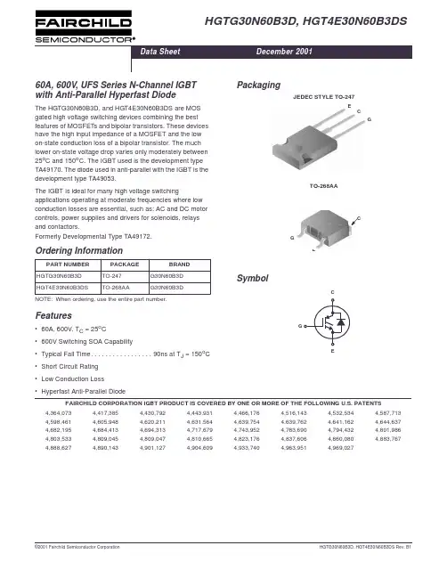
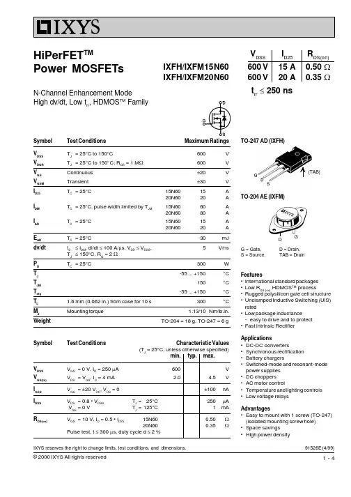
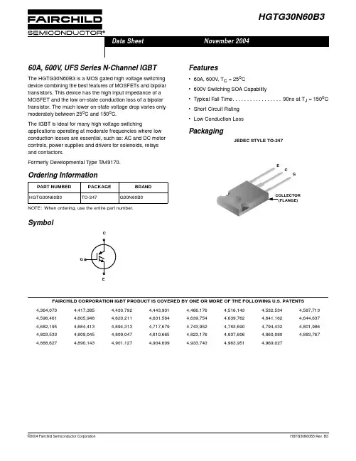
HGTG30N60B3D,HGT4E30N60B3DS60A,600V,UFS Series N-Channel IGBT with Anti-Parallel Hyperfast DiodeThe HGTG30N60B3D,and HGT4E30N60B3DS are MOS gated high voltage switching devices combining the best features of MOSFETs and bipolar transistors.These devices have the high input impedance of a MOSFET and the low on-state conduction loss of a bipolar transistor.The much lower on-state voltage drop varies only moderately between 25o C and 150o C.The IGBT used is the development type TA49170.The diode used in anti-parallel with the IGBT is the development type TA49053.The IGBT is ideal for many high voltage switchingapplications operating at moderate frequencies where low conduction losses are essential,such as:AC and DC motor controls,power supplies and drivers for solenoids,relays and contactors.Formerly Developmental Type TA49172.Features•60A,600V,T C =25o C•600V Switching SOA Capability•Typical Fall Time.................90ns at T J =150o C •Short Circuit Rating •Low Conduction Loss •Hyperfast Anti-Parallel DiodePackagingJEDEC STYLE TO-247TO-268AASymbolOrdering InformationNOTE:When ordering,usethe entire partnumber.GECGCECEGFAIRCHILD CORPORATION IGBT PRODUCT IS COVERED BY ONE OR MORE OF THE FOLLOWING U.S.PATENTS4,364,0734,417,3854,430,7924,443,9314,466,1764,516,1434,532,5344,587,7134,598,4614,605,9484,620,2114,631,5644,639,7544,639,7624,641,1624,644,6374,682,1954,684,4134,694,3134,717,6794,743,9524,783,6904,794,4324,801,9864,803,5334,809,0454,809,0474,810,6654,823,1764,837,6064,860,0804,883,7674,888,6274,890,1434,901,1274,904,6094,933,7404,963,9514,969,027Data SheetDecember 2001元器件交易网Absolute Maximum Ratings T C=25o C,Unless Otherwise SpecifiedHGTG30N60B3D,HGT4E30N60B3DS UNITS Collector to Emitter Voltage..............................................BV CES600V Collector Current ContinuousAt T C=25o C.........................................................I C2560AAt T C=110o C.......................................................I C11030A Average Diode Forward Current at110o C.................................I EC(AVG)25A Collector Current Pulsed(Note1)...........................................I CM220AGate to Emitter Voltage Continuous.........................................V GES±20VGate to Emitter Voltage Pulsed...........................................V GEM±30V Switching Safe Operating Area at T J=150o C(Figure2).......................SSOA60A at600VPower Dissipation Total at T C=25o C.........................................P D208WPower Dissipation Derating T C>25o C.......................................... 1.67W/o C Operating and Storage Junction T emperature Range........................T J,T STG-55to150o C Maximum Lead T emperature for Soldering.....................................T L260o CShort Circuit Withstand Time(Note2)at V GE=12V..............................t SC4µsShort Circuit Withstand Time(Note2)at V GE=10V..............................t SC10µs CAUTION:Stresses above those listed in“Absolute Maximum Ratings”may cause permanent damage to the device.This is a stress only rating and operation of the device at these or any other conditions above those indicated in the operational sections of this specification is not implied.NOTES:1.Pulse width limited by maximum junction temperature.2.V CE(PK)=360V,T J=125o C,R G=3Ω.Electrical Specifications T C=25o C,Unless Otherwise SpecifiedNOTE:3.Turn-Off Energy Loss (E OFF )is defined as the integral of the instantaneous power loss starting at the trailing edge of the input pulse and ending at the point where the collector current equals zero (I CE =0A).All devices were tested per JEDEC Standard No.24-1Method for Measurement of Power Device Turn-Off Switching Loss.This test method produces the true total Turn-Off Energy Loss.Typical Performance CurvesUnless Otherwise SpecifiedFIGURE 1.DC COLLECTOR CURRENT vs CASETEMPERATUREFIGURE 2.MINIMUM SWITCHING SAFE OPERATING AREAElectrical SpecificationsT C =25o C,Unless Otherwise Specified (Continued)T C ,CASE TEMPERATURE (o C)I C E ,D C C O L L E C T O R C U R R E N T (A )501004*********V GE =15V2575100125150V CE ,COLLECTOR TO EMITTER VOLTAGE (V)125700750I C E ,C O L L E C T O R T O E M I T T E R C U R R E N T (A )25503004002001005006001000150175200225T J =150o C,R G =3Ω,V GE =15V,L =100µHFIGURE 3.OPERATING FREQUENCY vs COLLECTOR TOEMITTER CURRENTFIGURE 4.SHORT CIRCUIT WITHSTAND TIMEFIGURE 5.COLLECTOR TO EMITTER ON-STATE VOLTAGE FIGURE 6.COLLECTOR TO EMITTER ON-STATE VOLTAGEFIGURE 7.TURN-ON ENERGY LOSS vs COLLECTOR TOEMITTER CURRENT FIGURE 8.TURN-OFF ENERGY LOSS vs COLLECTOR TOEMITTER CURRENTf M A X ,O P E R A T I N G F R E Q U E N C Y (k H z )5I CE ,COLLECTOR TO EMITTER CURRENT (A)10.110602040100f MAX1=0.05/(t d(OFF)I +t d(ON)I )R θJC =0.6o C/W,SEE NOTESP C =CONDUCTION DISSIPATION(DUTY FACTOR =50%)f MAX2=(P D -P C )/(E ON +E OFF )T C V GE 110o C10V15V 15V 75o C 110o C 75o C 10V 10T J =150o C,R G =3Ω,L =1mH,V CE =480VV GE ,GATE TO EMITTER VOLTAGE (V)I S C ,P E A K S H O R T C I R C U I T C U R R E N T (A )t S C ,S H O R T C I R C U I T W I T H S T A N D T I M E (µs )101112131415681012162014150200250300350400500t SCI SC18450V CE =360V,R G =3Ω,T J =125o C24V CE ,COLLECTOR TO EMITTER VOLTAGE (V)I C E ,C O L L E C T O R T O E M I T T E R C U R R E N T (A )02550756810150125100175T C =-55o CT C =150o CPULSE DURATION =250µs DUTY CYCLE <0.5%,V GE =10V 225200T C =25o CI C E ,C O L L E C T O R T O E M I T T E R C U R R E N T (A )V CE ,COLLECTOR TO EMITTER VOLTAGE (V)2002503003500120150********DUTY CYCLE <0.5%,V GE =15VPULSE DURATION =250µsT C =-55o CT C =150o CT C =25o C67E O N ,T U R N -O N E N E R G Y L O S S (m J )53I CE ,COLLECTOR TO EMITTER CURRENT (A)42140206050301060T J =25o C,T J =150o C,V GE =10VR G =3Ω,L =1mH,V CE =480VT J =25o C,T J =150o C,V GE =15VI CE ,COLLECTOR TO EMITTER CURRENT (A)E OF F ,T U R N -O F F E N E RG Y L O S S (m J )00.55030204060101.02.5R G =3Ω,L =1mH,V CE =480VT J =150o C,V GE =10V OR 15VT J =25o C,V GE =10V OR 15V2.01.53.03.54.04.5FIGURE 9.TURN-ON DELAY TIME vs COLLECTOR TOEMITTER CURRENT FIGURE 10.TURN-ON RISE TIME vs COLLECTOR TOEMITTER CURRENTFIGURE 11.TURN-OFF DELAY TIME vs COLLECTOR TOEMITTER CURRENT FIGURE 12.FALL TIME vs COLLECTOR TO EMITTERCURRENTFIGURE 13.TRANSFER CHARACTERISTIC FIGURE 14.GATE CHARGE WAVEFORMSI CE ,COLLECTOR TO EMITTER CURRENT (A)t d I ,T U R N -O N D E L A Y T I M E (n s )20103050253035404550405560T J =25o C,T J =150o C,V GE =10VT J =25o C,T J =150o C,V GE =15VR G =3Ω,L =1mH,V CE =480VI CE ,COLLECTOR TO EMITTER CURRENT (A)t r I ,R I S E T I M E (n s )200502502001006010150504030R G =3Ω,L =1mH,V CE =480VT J =25o C,T J =150o C,V GE =10VT J =25o C,T J =150o C,V GE =15V203060102503005040100200150I CE ,COLLECTOR TO EMITTER CURRENT (A)t d (O F F )I ,T U R N -O F F D E L A Y T I M E (n s )T J =25o C,V GE =10V,V GE =15VT J =150o C,V GE =10V,V GE =15V R G =3Ω,L =1mH,V CE =480VI CE ,COLLECTOR TO EMITTER CURRENT (A)t f I ,F A L L T I M E (n s )203060104010012050406080T J =150o C,V GE =10V AND 15VT J =25o C,V GE =10V AND 15VR G =3Ω,L =1mH,V CE =480VI C E ,C O L L E C T O R T O E M I T T E R C U R R E N T (A )501001505789106V GE ,GATE TO EMITTER VOLTAGE (V)112002503004T C =150o CT C =25o CPULSE DURATION =250µsDUTY CYCLE <0.5%,V CE =10V T C =-55o CQ G ,GATE CHARGE (nC)0810642050V G E ,G A T E T O E M I T T E R V O L T A G E (V )V CE =400VV CE =600V150200100121416V CE =200VI g (REF)=1mA,R L =10Ω,T C =25o CFIGURE 15.CAPACITANCE vs COLLECTOR TO EMITTER VOLTAGEFIGURE 16.NORMALIZED TRANSIENT THERMAL RESPONSE,JUNCTION TO CASEFIGURE 17.DIODE FORWARD CURRENT vs FORWARDVOLTAGE DROPFIGURE 18.RECOVERY TIME vs FORWARD CURRENTV CE ,COLLECTOR TO EMITTER VOLTAGE (V)5101520250C ,C A P A C I T A N C E (n F )246810C RESFREQUENCY =1MHzC OES C IESZ θJ C ,N O R M A L I Z E D T H E R M A L R E S P O N S Et 1,RECTANGULAR PULSE DURATION (s)10-510-310010110-4DUTY FACTOR,D =t 1/t 2PEAK T J =(P D X Z θJC X R θJC )+T C10-110-2SINGLE PULSE10010-110-2P Dt 1t 20.500.050.010.020.100.20I E C ,F O R W A R D C U R R E N T (A )V EC ,FORWARD VOLTAGE (V)3.02.02.51.51.00.50255075100125 3.54.0150175200100o C25o C-55o C304020t ,R E C O V E R Y T I M E S (n s )I EC ,FORWARD CURRENT (A)2301101020505t rr t at bT C =25o C,dI EC /dt =200A/µsHandling Precautions for IGBTsInsulated Gate Bipolar Transistors are susceptible to gate-insulation damage by the electrostatic discharge of energy through the devices.When handling these devices,care should be exercised to assure that the static charge built in the handler’s body capacitance is not discharged through the device.With proper handling and application procedures,however,IGBT s are currently being extensively used inproduction by numerous equipment manufacturers in military,industrial and consumer applications,with virtually no damage problems due to electrostatic discharge.IGBT s can be handled safely if the following basic precautions are taken:1.Prior to assembly into a circuit,all leads should be kept shorted together either by the use of metal shorting springs or by the insertion into conductive material such as “ECCOSORBD™LD26”or equivalent.2.When devices are removed by hand from their carriers,the hand being used should be grounded by any suitable means -for example,with a metallic wristband.3.Tips of soldering irons should be grounded.4.Devices should never be inserted into or removed from circuits with power on.5.Gate Voltage Rating -Never exceed the gate-voltagerating of V GEM .Exceeding the rated V GE can result in permanent damage to the oxide layer in the gate region.6.Gate Termination -The gates of these devices are essentially capacitors.Circuits that leave the gate open-circuited or floating should be avoided.Theseconditions can result in turn-on of the device due to voltage buildup on the input capacitor due to leakage currents or pickup.7.Gate Protection -These devices do not have an internal monolithic Zener diode from gate to emitter.If gateprotection is required an external Zener is recommended.Operating Frequency InformationOperating frequency information for a typical device (Figure 3)is presented as a guide for estimating device performance for a specific application.Other typicalfrequency vs collector current (I CE )plots are possible using the information shown for a typical unit in Figures 5,6,7,8,9and 11.The operating frequency plot (Figure 3)of a typical device shows f MAX1or f MAX2;whichever is smaller at each point.The information is based on measurements of a typical device and is bounded by the maximum rated junction temperature.f MAX1is defined by f MAX1=0.05/(t d(OFF)I +t d(ON)I ).Deadtime (the denominator)has been arbitrarily held to 10%of the on-state time for a 50%duty factor.Other definitions are possible.t d(OFF)I and t d(ON)I are defined in Figure 20.Device turn-off delay can establish an additional frequency limiting condition for an application other than T JM .t d(OFF)I is important when controlling output ripple under a lightly loaded condition.f MAX2is defined by f MAX2=(P D -P C )/(E OFF +E ON ).The allowable dissipation (P D )is defined by P D =(T JM -T C )/R θJC .The sum of device switching and conduction losses must not exceed P D .A 50%duty factor was used (Figure 3)and theconduction losses (P C )are approximated by P C =(V CE x I CE )/2.E ON and E OFF are defined in the switching waveformsshown in Figure 20.E ON is the integral of the instantaneous power loss (I CE x V CE )during turn-on and E OFF is theintegral of the instantaneous power loss (I CE x V CE )during turn-off.All tail losses are included in the calculation for E OFF ;i.e.,the collector current equals zero (I CE =0).Test Circuit and WaveformsFIGURE 19.INDUCTIVE SWITCHING TEST CIRCUIT FIGURE 20.SWITCHING TEST WAVEFORMSR G =3ΩL =1mHV DD =480V+-HGTG30N60B3Dt fIt d(OFF)It rI t d(ON)I10%90%10%90%V CEI CEV GEE OFFE ON。
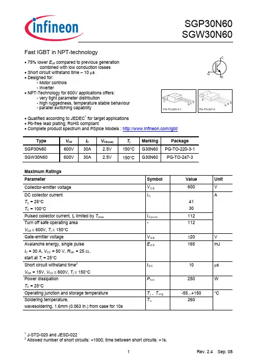
Fast IGBT in NPT-technology• 75% lower E off compared to previous generationcombined with low conduction losses• Short circuit withstand time – 10 µs• Designed for:- Motor controls- Inverter• NPT-Technology for 600V applications offers:- very tight parameter distribution - high ruggedness, temperature stable behaviour - parallel switching capability• Qualified according to JEDEC 1 for target applications • Pb-free lead plating; RoHS compliant• Complete product spectrum and PSpice Models : /igbt/TypeV CEI CV CE(sat )T j MarkingPackage SGP30N60 600V 30A 2.5V 150°C G30N60PG-TO-220-3-1 SGW30N60 600V 30A 2.5V 150°CG30N60PG-TO-247-3Maximum RatingsParameter Symbol Value Unit Collector-emitter voltage V C E 600 V DC collector current T C = 25°C T C = 100°CI C41 30Pulsed collector current, t p limited by T jmax I C p u l s 112Turn off safe operating area V CE ≤ 600V, T j ≤ 150°C -112AGate-emitter voltageV G E±20VAvalanche energy, single pulse I C = 30 A, V CC = 50 V, R GE = 25 Ω, start at T j = 25°CE A S 165 mJ Short circuit withstand time 2 V GE = 15V, V CC ≤ 600V, T j ≤ 150°C t S C 10 µs Power dissipation T C = 25°CP t o t 250 W Operating junction and storage temperature T j , T s t g -55...+150 Soldering temperature,wavesoldering, 1.6mm (0.063 in.) from case for 10sT s 260°C1 J-STD-020 and JESD-0222Allowed number of short circuits: <1000; time between short circuits: >1s.Thermal ResistanceParameter Symbol Conditions Max. Value Unit CharacteristicIGBT thermal resistance, junction – case R t h J C0.5 K/WThermal resistance, junction – ambient R t h J A PG-TO-220-3-1PG-TO-247-3-2162 40Electrical Characteristic, at T j = 25 °C, unless otherwise specifiedValue Parameter Symbol Conditions min. Typ. max. UnitStatic CharacteristicCollector-emitter breakdown voltage V (B R )C E S V G E =0V, I C =500µA 600 - - Collector-emitter saturation voltageV C E (s a t )V G E = 15V, I C =30A T j =25°C T j =150°C1.7 -2.1 2.5 2.43.0 Gate-emitter threshold voltage V G E (t h ) I C =700µA,V C E =V G E 3 4 5V Zero gate voltage collector currentI C E SV C E =600V,V G E =0V T j =25°C T j =150°C- -- -40 3000µAGate-emitter leakage current I G E S V C E =0V,V G E =20V - - 100 nA Transconductance g f s V C E =20V, I C =30A- 20 - SDynamic Characteristic Input capacitance C i s s - 1600 1920 Output capacitanceC o s s - 150 180Reverse transfer capacitance C r s s V C E =25V,V G E =0V, f =1MHz - 92 110 pF Gate chargeQ G a t eV C C =480V, I C =30A V G E =15V- 140 182 nCInternal emitter inductancemeasured 5mm (0.197 in.) from case L E PG-TO-220-3-1PG-TO-247-3-21 - -7 13- nHShort circuit collector current 2)I C (S C ) V G E =15V,t S C ≤10µs V C C ≤ 600V, T j ≤ 150°C- 300 - A2)Allowed number of short circuits: <1000; time between short circuits: >1s.Switching Characteristic, Inductive Load, at T j =25 °CValueParameter Symbol Conditions min. typ. max. UnitIGBT Characteristic Turn-on delay time t d (o n ) - 44 53 Rise timet r - 34 40Turn-off delay time t d (o f f ) - 291 349 Fall time t f - 58 70 ns Turn-on energy E o n - 0.64 0.77 Turn-off energy E o f f - 0.65 0.85 Total switching energyE t sT j =25°C, V C C =400V,I C =30A,V G E =0/15V,R G =11Ω,L σ1) =180nH, C σ1)=900pFEnergy losses include“tail” and diodereverse recovery. - 1.29 1.62 mJSwitching Characteristic, Inductive Load, at T j =150 °CValueParameter Symbol Conditions min. typ. max. UnitIGBT Characteristic Turn-on delay time t d (o n ) - 44 53 Rise timet r - 34 40Turn-off delay time t d (o f f ) - 324 389 Fall time t f - 67 80 ns Turn-on energy E o n - 0.98 1.18Turn-off energy E o f f - 0.92 1.19 Total switching energyE t sT j =150°C V C C =400V,I C =30A,V G E =0/15V,R G = 11Ω,L σ1) =180nH, C σ1)=900pFEnergy losses include“tail” and diodereverse recovery. - 1.90 2.38 mJ1)Leakage inductance L σ and Stray capacity C σ due to dynamic test circuit in Figure E.I C , C O L L E C T O R C U R R E N T10Hz100Hz 1kHz 10kHz 100kHz0A 20A 40A 60A 80A100A 120A 140A 160AI C , C O L L E C T O R C U R R E N T1V10V 100V 1000V0.1A1A10A100Af , SWITCHING FREQUENCYV CE , COLLECTOR -EMITTER VOLTAGE Figure 1. Collector current as a function of switching frequency(T j ≤ 150°C, D = 0.5, V CE = 400V, V GE = 0/+15V, R G = 11Ω) Figure 2. Safe operating area (D = 0, T C = 25°C, T j ≤ 150°C)P t o t , P O W E R D I S S I P A T I O N25°C50°C 75°C 100°C 125°C0W 50W100W150W200W250W 300WI C , C O L L E C T O R C U R R E N T25°C50°C 75°C 100°C 125°C0A10A20A30A40A50A60AT C , CASE TEMPERATURET C , CASE TEMPERATUREFigure 3. Power dissipation as a function of case temperature (T j ≤ 150°C)Figure 4. Collector current as a function of case temperature(V GE ≤ 15V, T j ≤ 150°C)I C , C O L L E C T O R C U R R E N T0V1V 2V 3V 4V 5V 0A 10A 20A 30A 40A 50A 60A 70A80A90A I C , C O L L E C T O R C U R R E N T0V1V 2V 3V 4V 5V0A 10A 20A 30A 40A 50A 60A 70A80A90AV CE , COLLECTOR -EMITTER VOLTAGEV CE , COLLECTOR -EMITTER VOLTAGE Figure 5. Typical output characteristics (T j = 25°C) Figure 6. Typical output characteristics (T j = 150°C)I C , C O L L E C T O R C U R R E N T0V2V 4V 6V 8V 10V0A 10A20A 30A 40A 50A 60A 70A 80A90A 100A V C E (s a t ), C O L L E C T O R -E M I T T E R S A T U R A T I O N V O L T A G E-50°C 0°C 50°C 100°C 150°C1.0V1.5V2.0V2.5V3.0V3.5V4.0VV GE , GATE -EMITTER VOLTAGETj , JUNCTION TEMPERATUREFigure 7. Typical transfer characteristics (V CE = 10V)Figure 8. Typical collector-emittersaturation voltage as a function of junction temperature (V GE = 15V)t , S W I T C H I N G T I M E S10A 20A 30A 40A 50A 60A10ns100ns1000nst , S W I T C H I N G T I M E S0Ω10Ω20Ω30Ω40Ω10ns100ns1000nsI C , COLLECTOR CURRENTR G , GATE RESISTORFigure 9. Typical switching times as a function of collector current(inductive load, T j = 150°C, V CE = 400V, V GE = 0/+15V, R G = 11Ω,Dynamic test circuit in Figure E) Figure 10. Typical switching times as a function of gate resistor(inductive load, T j = 150°C, V CE = 400V, V GE = 0/+15V, I C = 30A,Dynamic test circuit in Figure E)t , S W I T C H I N G T I M E S0°C50°C 100°C 150°C 10ns100ns1000nsV G E (t h ), G A T E -E M I T T E R T H R E S H O L D V O L T A G E-50°C0°C 50°C 100°C 150°C2.0V2.5V3.0V 3.5V4.0V 4.5V5.0V 5.5VT j , JUNCTION TEMPERATURET j , JUNCTION TEMPERATUREFigure 11. Typical switching times as a function of junction temperature(inductive load, V CE = 400V, V GE = 0/+15V, I C = 30A, R G = 11Ω,Dynamic test circuit in Figure E)Figure 12. Gate-emitter threshold voltage as a function of junction temperature (I C = 0.7mA)E , S W I T C H I N G E N E R G Y L O S S E S10A20A 30A 40A 50A 60A 70A 0.0mJ0.5mJ 1.0mJ 1.5mJ 2.0mJ 2.5mJ 3.0mJ 3.5mJ 4.0mJ 4.5mJ5.0mJE ,S W I T C H I N G E N E R G Y L O S S E S0Ω10Ω20Ω30Ω40Ω0.0mJ0.5mJ 1.0mJ 1.5mJ 2.0mJ 2.5mJ 3.0mJ 3.5mJ4.0mJI C , COLLECTOR CURRENTR G , GATE RESISTORFigure 13. Typical switching energy losses as a function of collector current(inductive load, T j = 150°C, V CE = 400V, V GE = 0/+15V, R G = 11Ω,Dynamic test circuit in Figure E) Figure 14. Typical switching energy losses as a function of gate resistor(inductive load, T j = 150°C, V CE = 400V, V GE = 0/+15V, I C = 30A,Dynamic test circuit in Figure E)E , S W I T C H I N G E N E R G Y L O S S E S0°C50°C 100°C 150°C0.0mJ0.5mJ1.0mJ1.5mJ2.0mJ2.5mJ3.0mJZ t h J C , T R A N S I E N T T H E R M A L I M P E D A N C E1µs10µs 100µs 1ms 10ms 100ms 1s10-4K/W10-3K/W10-2K/W10-1K/W100K/WT j , JUNCTION TEMPERATUREt p , PULSE WIDTHFigure 15. Typical switching energy losses as a function of junction temperature (inductive load, V CE = 400V, V GE = 0/+15V, I C = 30A, R G = 11Ω,Dynamic test circuit in Figure E)Figure 16. IGBT transient thermalimpedance as a function of pulse width (D = t p / T )V G E , G A T E -E M I T T E R V O L T AG E0nC50nC 100nC 150nC 200nC0V 5V10V15V20V25VC , C A P A C I T A N C E0V10V 20V 30V10pF100pF1nFQ GE , GATE CHARGEV CE , COLLECTOR -EMITTER VOLTAGE Figure 17. Typical gate charge (I C = 30A) Figure 18. Typical capacitance as a function of collector-emitter voltage (V GE = 0V, f = 1MHz)t s c , S H O R T C I R C U I T W I T H S T A N D T I M E10V11V12V13V14V15V0µs 5µs10µs15µs20µs25µsI C (s c ), S H O R T C I R C U I T C O L L E C T O R C U R R EN T10V12V 14V 16V 18V 20V0A 50A 100A 150A 200A 250A 300A 350A 400A 450A 500AV GE , GATE -EMITTER VOLTAGEV GE , GATE -EMITTER VOLTAGEFigure 19. Short circuit withstand time as a function of gate-emitter voltage (V CE = 600V, start at T j = 25°C)Figure 20. Typical short circuit collector current as a function of gate-emitter voltage (V CE ≤ 600V, T j = 150°C)PG-TO-220-3-1PG-TO247-3Figure A. Definition of switching timesFigure B. Definition of switching lossesp(t)12nT (t)j τ11τ22nnτT Cr r r r r r Figure D. Thermal equivalent circuitFigure E. Dynamic test circuit Leakage inductance L σ =180nH and Stray capacity C σ =900pF.Published byInfineon Technologies AG81726 Munich, Germany© 2008 Infineon Technologies AGAll Rights Reserved.Legal DisclaimerThe information given in this document shall in no event be regarded as a guarantee of conditions or characteristics. With respect to any examples or hints given herein, any typical values stated herein and/or any information regarding the application of the device, Infineon Technologies hereby disclaims any and all warranties and liabilities of any kind, including without limitation, warranties of non-infringement of intellectual property rights of any third party.InformationFor further information on technology, delivery terms and conditions and prices, please contact the nearest Infineon Technologies Office ().WarningsDue to technical requirements, components may contain dangerous substances. For information on the types in question, please contact the nearest Infineon Technologies Office. Infineon Technologies components may be used in life-support devices or systems only with the express written approval of Infineon Technologies, if a failure of such components can reasonably be expected to cause the failure of that life-support device or system or to affect the safety or effectiveness of that device or system. Life support devices or systems are intended to be implanted in the human body or to support and/or maintain and sustain and/or protect human life. If they fail, it is reasonable to assume that the health of the user or other persons may be endangered.。
30n60场效应管参数摘要:1.场效应管简介2.30n60场效应管参数3.参数对性能的影响4.应用领域正文:场效应管(FET)是一种半导体器件,基于栅极和源极、漏极之间的电场效应来控制电流。
在众多场效应管型号中,30n60是一种常见的型号,具有较高的性能和广泛的应用。
一、场效应管简介场效应管是半导体器件的一种,具有输入阻抗高、放大倍数大、功耗低等优点。
根据结构和工作原理的不同,场效应管可分为金属氧化物半导体场效应管(MOSFET)和双极性晶体管(BJT)等。
二、30n60场效应管参数1.漏极电压(Vds):30n60场效应管的漏极电压可以达到600V,具有较高的耐压能力。
2.栅极电压(Vgs):该型号场效应管的栅极电压范围为-20V至+10V。
3.电流(Ids):30n60场效应管的最大漏极电流为60A。
4.导通电阻(Rdson):该型号场效应管的导通电阻在25℃时为0.025Ω,具有较低的导通电阻。
5.耗尽模式和增强模式:30n60场效应管既有耗尽模式,也有增强模式,可根据实际应用需求选择。
三、参数对性能的影响1.漏极电压(Vds):较高的漏极电压可以承受更大的电压波动,有利于提高设备的稳定性。
2.栅极电压(Vgs):合适的栅极电压范围可以保证场效应管正常工作,并具有较好的驱动性能。
3.电流(Ids):较大的电流能力能够满足高功率应用的需求。
4.导通电阻(Rdson):较低的导通电阻有助于降低功耗,提高工作效能。
5.模式:根据不同的工作条件和性能要求,选择合适的模式,可以优化电路设计。
四、应用领域1.电源管理:30n60场效应管广泛应用于开关电源、线性稳压器等电源管理领域。
2.电机驱动:高耐压、大电流能力的特性使其成为电机驱动的理想选择,如伺服电机、步进电机等。
3.工业控制:在工业控制领域,30n60场效应管可用于逆变器、变频器等设备。
4.消费电子:该型号场效应管在消费电子设备中也有广泛应用,如适配器、充电器等。
30n60场效应管参数摘要:1.30n60 场效应管简介2.30n60 场效应管参数详解2.1 静态工作点2.2 输入阻抗2.3 输出阻抗2.4 增益2.5 频率响应2.6 功率正文:【30n60 场效应管简介】30n60 场效应管是一种常见的场效应晶体管,广泛应用于放大电路、开关电路和振荡电路等电子电路中。
其中,“30”和“60”分别代表了该场效应管的源极和漏极间的最大耗散功率,即30W 和60W。
这种场效应管以其高输入阻抗、低噪声和低失真等优点在电子设备中获得了广泛的应用。
【30n60 场效应管参数详解】30n60 场效应管的主要参数包括静态工作点、输入阻抗、输出阻抗、增益、频率响应和功率等,下面我们将详细地介绍这些参数。
【2.1 静态工作点】静态工作点是指场效应管工作在一个恒定的直流电压和电流条件下的点。
在静态工作点附近,场效应管的输入阻抗和输出阻抗最低,增益最高,因此,设计电路时需要尽可能使场效应管工作在静态工作点附近。
【2.2 输入阻抗】输入阻抗是指场效应管的输入端对电路的阻抗。
30n60 场效应管的输入阻抗很高,一般在10^8 欧姆以上,这使得它在电路中可以降低输入电流,提高电路的输入阻抗,从而降低噪声和失真。
【2.3 输出阻抗】输出阻抗是指场效应管的输出端对电路的阻抗。
30n60 场效应管的输出阻抗较低,一般在几十欧姆到几百欧姆之间,这使得场效应管可以提供较大的输出电流,驱动后级负载。
【2.4 增益】增益是指场效应管的电压放大倍数。
30n60 场效应管的增益通常在20-100 倍之间,具体数值取决于电路的设计和工作点。
【2.5 频率响应】频率响应是指场效应管在不同频率下的放大倍数。
30n60 场效应管的频率响应通常在直流到几百千赫之间,具体数值也取决于电路的设计和工作点。
【2.6 功率】功率是指场效应管能够承受的最大功率。
30n60 场效应管的最大耗散功率分别为30W 和60W,超过这个值会导致场效应管过热,损坏电路。
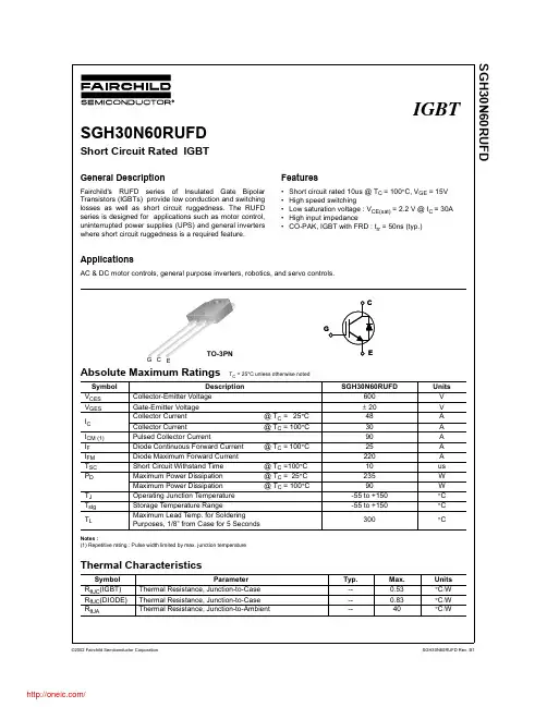
30n60场效应管参数摘要:1.场效应管的基本概念2.30n60场效应管的参数概述3.30n60场效应管的电气特性4.30n60场效应管的应用领域5.选购与使用30n60场效应管的注意事项正文:场效应管(Field Effect Transistor,简称FET)是一种半导体器件,根据其导电方式可分为增强型、耗尽型两种。
它具有输入电阻高、噪声低、功耗小等优点,广泛应用于放大、开关、调制、功率控制等电路。
30n60场效应管是一种N沟道增强型金属氧化物半导体(MOSFET)器件,其中“30”表示其漏极电流ID为30A,“60”表示其最大耗散功率为60W。
接下来,我们将详细了解30n60场效应管的参数和应用。
一、30n60场效应管的电气特性1.漏极电流ID:30A(最大值)2.栅极电流IG:100μA(最大值)3.输入阻抗:100MΩ(最小值)4.输出阻抗:20Ω(最大值)5.最大耗散功率:60W6.工作温度范围:-55℃ ~ 150℃二、30n60场效应管的应用领域1.放大器:30n60场效应管可作为放大器的主放大器,具有较高的输入电阻和较低的噪声,可实现宽带放大。
2.开关电源:30n60场效应管具有较低的导通电阻和较高的开关速度,适用于高频开关电源中的开关元件。
3.电机驱动:30n60场效应管具有较大的电流容量和较高的耐压能力,可用于驱动直流电机、交流电机等。
4.无线通信:30n60场效应管在射频电路中有良好的表现,可应用于功率放大器和开关。
三、选购与使用30n60场效应管的注意事项1.确保工作电压和工作电流符合电路需求。
2.考虑场效应管的输入阻抗、输出阻抗和开关速度等参数,以满足电路性能要求。
3.考虑场效应管的封装和散热能力,确保在高温环境下稳定工作。
4.注意电路保护措施,防止过电压、过电流等异常情况对场效应管造成损坏。
总之,30n60场效应管作为一种高性能的半导体器件,具有广泛的应用前景。
初三化学上册分专题复习练习题专题一物质的组成与分类1.现有C、H、O、Na、Cu、S六种元素,从中选出相关元素组成下列类别物质的化学式:(每类各写两例)⑴单质⑵酸⑶碱⑷盐⑸氧化物⑹有机物2.化学来自于生活,用于生活,下表是生活中常用物质溶液的PH值及主要成分的化⑴将上表①~⑤中主要成分进行分类(填序号,下同):属于酸的是__________;属于碱的是_________;属于盐的是__________;属于有机物的是__________。
⑵当有人被蚊虫(释放一种酸性物质)叮咬后,为减轻疼痛,可在伤处涂_________⑶用久的铝壶内有水垢(主要成分为CaCO3、Mg(OH)2可用_________少量多次清除。
3.下列物质:①氮气②铜丝③二氧化锰④液氧⑤空气⑥白磷⑦碱式碳酸铜加热完全反应后的固体物质⑧实验室用高锰酸钾制取氧气后的固体物质⑨水银。
九种物质中用序号填写符合下列要求的物质(1)属于混合物的是____________(2)属于纯净物的是____________(3)属于化合物的是____________(4)属于单质的是_____________(5)属于氧化物的是____________(6)属于金属单质是_____________4.下列各组物质中,都属于混合物的是()A、海水、水银B、不锈钢刀具、铁矿石C、干冰、冰水混合物D、氧化铁、铁锈5.某物质经分析只有一种元素,该物质不可能是()A、单质B、化合物C、纯净物D、由分子构成的物质6.包裹松花蛋的泥灰料的配料中,含纯碱、草木灰(主要成分为碳酸钾)、食盐、生石灰等,不属于盐类的是()A、纯碱B、食盐C、碳酸钾D、生石灰7.金属钛(Ti)是航空、宇航等方面的重要原料,在生产钛的过程中,可用镁和四氯化钛(TiCl4)在加热条件下制取,则四氯化钛属于……………………()A、金属B、化合物C、混合物D、氧化物8.科学家用计算机模拟后确认,60个N原子结合成N60分子,下列关于N60的叙述正确的是()A、N60是一种新型化合物B、N60和N2性质完全相同C、一个N60分子中有30个N2分子D、N60和N2混合形成的是混合物9.在①MgO、CuO、CaO、SO2;②C、Fe、S、P;③ZnCl2、BaCO3、HNO3、NaNO3三组物质中,每组各有一种物质在分类与组内其它物质不同,这三种物质分别是() A、CuO、Fe、S、ZnCl2 B、SO2、Fe、HNO3C、CaO、C、BaCO3、HNO3D、SO2、S、NaNO310.(07无锡)下列物质不属于有机化合物的是A.醋酸 B.酒精 C.食盐 D.葡萄糖11.(07苏州)下列物质属于氧化物是是A.氧气(O2) B.水(H2O)C.乙醇(C2H6O) D.氯化钴(CoCl2)12.(07南通)分类法是一种行之有效、简单易行的科学方法,人们在认识事物时可以采取多种分类方法。
ten30度的值-回复什么是十三十度的值?十三十度,也可以写作ten30度,指的是一个角度的度数。
在直角坐标系中,一个完整的圆周由360度组成,而十三十度则是在正轴线上旋转60度后的位置。
当一个角度的度数为十三十度时,它位于正轴线上,与x轴正方向形成一个60度的角。
这意味着这个角是一个锐角,同时它也是一个特殊的角度,因为它是等边三角形中的内角之一。
在等边三角形中,所有三个角度都是六十度。
在实际生活和数学问题中,十三十度能够代表许多事物和概念。
下面将逐步介绍十三十度的值在不同领域中的应用。
首先,在几何学中,十三十度是一个重要的角度。
如前所述,它是等边三角形的内角之一,这意味着如果你在纸上画一个等边三角形,那么每个角度都是60度,其中一个角度就是十三十度。
除了等边三角形,十三十度也出现在其他几何图形中,例如六边形和十二边形,这些图形的内角和为360度。
因此,了解十三十度的性质和应用对于解决几何问题非常重要。
其次,在物理领域中,十三十度代表了光的折射现象。
光的折射指的是光线通过两种不同介质之间的边界时发生的偏折现象。
当光线从一个介质进入另一个介质时,光线的传播方向会发生变化。
折射定律描述了光线折射的规律,其中涉及十三十度的概念。
根据折射定律,入射角、折射角和介质的折射率之间有一个简单的关系。
对于一个光线从真空进入另一个介质的情况,当入射角为十三十度时,它的折射角也是十三十度。
第三,在三角函数中,十三十度对应着根号三除以二的值。
三角函数是数学中与角度相关的函数,它们包括正弦、余弦和正切等。
这些函数在解决几何和物理问题中非常常见。
例如,当角度为十三十度时,三角函数的值可以通过查阅三角函数表或使用计算器来得到。
对于角度为十三十度的正弦、余弦和正切函数值分别为0.866、0.5和1.732。
除了几何、物理和数学领域,十三十度的值还在日常生活中的许多方面有所应用。
例如,如果你是一名厨师,那么你会知道将火腿或者培根切成正好能够放入三明治的尺寸需要将它们切成薄片,而每一片的角度约为十三十度。
频率转速计算公式以频率转速计算公式为标题,本文将介绍频率与转速之间的关系,并详细阐述频率转速计算公式的应用。
我们来了解一下频率和转速的定义。
频率是指单位时间内发生的周期性事件的次数,通常用赫兹(Hz)来表示。
而转速是指物体单位时间内旋转的圈数,通常用转每分钟(rpm)来表示。
频率和转速之间存在着一定的关系,可以通过频率转速计算公式来相互转换。
具体而言,频率与转速之间的关系可以通过以下公式表示:转速 = 频率× 60其中,转速表示转每分钟,频率表示赫兹。
通过这个公式,我们可以根据已知的频率值来计算对应的转速。
举个例子来说明,假设某电机的转速为1800rpm,我们想要计算对应的频率。
根据频率转速计算公式,我们可以得到如下计算过程:转速 = 频率× 601800 = 频率× 60频率 = 1800 / 60频率 = 30 Hz因此,当电机的转速为1800rpm时,对应的频率为30赫兹。
在实际工程中,频率转速计算公式的应用非常广泛。
例如,在机械工程中,通过测量旋转物体的转速,可以计算得到其对应的频率,从而判断设备是否正常运行。
在电气工程中,通过测量电机的频率,可以计算得到其转速,从而控制电机的运行速度。
频率转速计算公式还可以应用于音乐领域。
在音乐中,音调的高低与频率有直接的关系。
通过测量音乐中的频率,可以计算得到对应的转速,从而了解音乐的快慢和节奏。
总结起来,频率转速计算公式是一种重要的工程计算工具,可以帮助我们在实际应用中准确地计算频率和转速之间的转换关系。
通过掌握这个公式,我们可以更好地理解和应用频率和转速的概念,并在工程实践中取得更好的成果。
希望本文对读者们有所帮助,谢谢阅读!。
数控机床操作与编程练习题与标准答案作者: 日期:数控机床操作与编程练习题与答案填空题1. ________________________ 操作面板一般有、机床操作面板。
2. 数字控制系统简称NC系统,计算机控制系统简称 _________ 系统。
3 .请写出下列常用缩写的英文全称:CNC _______4 . RS232主要作用是用于程序的。
5 .车床的刀具号T0101,前面两位数字表示___________ ,后面两位数字表示刀具补偿号。
6 . G49用来取消刀具 ________ 卜偿。
7 . G40用来取消刀具 ___ 补偿。
8 .在车床上表示X坐标值,通常采用__________ 编程。
9. ____ 插补指令分顺时针G02和逆时针G03。
10. 指令“ G04 X-"中,X值的含意是时间,不是坐标。
11. 数控机床的Z轴一般与主轴轴线重合或平行,正方向以刀具_工件方向为准。
12. __________________________________________ 数控程序编制中,尺寸系统有绝对值编程,值编程和混合编程。
13. 圆弧插补需要指定插补平面,用G17/G18/G19指令。
默认指令一般为 _,可不写。
14. 切入点是刀具可以由此直接进入切削的刀具位置点。
一般要求刀具切削表面反向延长线或_切入工件。
15. 返回参考点有_和自动返回参考点两种。
16. 数控机床通电后,必须首先寻找机床参考点,即 _,使各坐标轴均返回各自的参考点,从而确定了机床坐标系后,才能进行其他操作。
17. 车床加工时,刀具的换刀点通常设置在工件的位置,以免和工件发生碰撞。
18、G代码中的_____ 指令,只在所在程序段中有效。
19、进给速度是刀具向工件进给的相对速度,有两种单位即_和mm/r,可以分别用G98和G99指令来指定。
20、接通恒线速控制用G96指令,取消恒线速控制用 _指令。
21、通过旋转机床面板上的转速倍率开关,可在不停机主轴旋转中调节主轴_。
VN30NHIGH SIDE SMART POWER SOLID STATE RELAYPRELIMINARY DATAsOUTPUT CURRENT (CONTINUOUS):45A @T c =25o Cs 5V LOGIC LEVEL COMPATIBLE INPUT s THERMAL SHUT-DOWNs UNDER VOLTAGE SHUT-DOWNs OPEN DRAIN DIAGNOSTIC OUTPUT sVERY LOW STAND-BY POWER DISSIPATIONDESCRIPTIONThe VN30N is a monolithic device made using SGS-THOMSON Vertical Intelligent Power Technology,intended for driving resistive or inductive loads with one side grounded.Built-in thermal shut-down protects the chip from over temperature and short circuit.The input control is 5V logic level compatible.The open drain diagnostic output indicates open circuit (no load)and over temperature status.September 1994BLOCK DIAGRAMTYPE V DSS R DS(on)I OUT V C C VN30N60V0.03Ω45A26VPENTAWATT (vertical)PENTAWATT (horizontal)PENTAWATT (in-line)ORDER CODES:PENTAWATT vertical VN30NPENTAWATT horizontal VN30N (011Y)PENTAWATT in-line VN30N (012Y)1/10VN30NABSOLUTE MAXIMUM RATINGSymbol Parameter Value Unit V(BR)DSS Drain-Source Breakdown Voltage60VI O UT Output Current(cont.)45AI R Reverse Output Current-45AI I N Input Current±10mA-V CC Reverse Supply Voltage-4VI STA T Status Current±10mAV E SD Electrostatic Discharge(1.5kΩ,100pF)2000V P tot Power Dissipation at T c≤25o C108W T j Junction Operating Temperature-40to150o C T stg Storage Temperature-55to150o CCONNECTION DIAGRAMCURRENT AND VOLTAGE CONVENTIONS2/10THERMAL DATAR thj-cas e R thj-amb Thermal Resistance Junction-case MaxThermal Resistance Junction-ambient Max1.1560o C/Wo C/WELECTRICAL CHARACTERISTICS(V CC=13V;-40≤T j≤125o C unless otherwise specified) POWERSymbol Parameter Test Conditions Min.Typ.Max.Unit V C C Supply Voltage726VR on On State Resistance I OU T=18AI OU T=18A T j=25o C 0.060.03ΩΩI S Supply Current Off State T j≥25o COn State 5015µAmASWITCHINGSymbol Parameter Test Conditions Min.Typ.Max.Unitt d(on)Turn-on Delay Time OfOutput Current I OU T=18A Resistive LoadInput Rise Time<0.1µs T j=25o C30µst r Rise Time Of OutputCurrent I OU T=18A Resistive LoadInput Rise Time<0.1µs T j=25o C100µst d(off)Turn-off Delay Time OfOutput Current I OU T=18A Resistive LoadInput Rise Time<0.1µs T j=25o C80µst f Fall Time Of OutputCurrent I OU T=18A Resistive LoadInput Rise Time<0.1µs T j=25o C40µs(di/dt)on Turn-on Current Slope I OU T=18AI OU T=I OV 0.53A/µsA/µs(di/dt)off Turn-off Current Slope I OU T=18AI OU T=I OV 34A/µsA/µsLOGIC INPUTSymbol Parameter Test Conditions Min.Typ.Max.Unit V IL Input Low LevelVoltage0.8VV IH Input High LevelVoltage2(*)VV I(hy st.)Input HysteresisVoltage0.5VI I N Input Current V IN=5V250500µAV ICL Input Clamp Voltage I IN=10mAI IN=-10mA6-0.7VVPROTECTIONS AND DIAGNOSTICSSymbol Parameter Test Conditions Min.Typ.Max.Unit V STAT(•)Status Voltage OutputLowI STAT=1.6mA0.4VV US D Under Voltage ShutDown 6.57VVN30N3/10ELECTRICAL CHARACTERISTICS(continued)PROTECTION AND DIAGNOSTICS(continued)Symbol Parameter Test Conditions Min.Typ.Max.UnitV S CL(•)Status Clamp Voltage I STAT=10mAI STAT=-10mA6-0.7VVt S C Switch-off Time inShort Circuit Conditionat Start-UpR LOA D<10mΩT c=25o C1msI OV Over Current R LOA D<10mΩ-40≤T c≤125o C140AI AV Average Current inShort CircuitR LOA D<10mΩT c=85o C 2.5AI OL Open Load CurrentLevel51250mAT TS D Thermal Shut-downTemperature140o C T R Reset Temperature125o C(*)The V IH is internally clamped at6V about.It is possible to connect this pin to an higher voltage via an external resistor calculated to not exceed10mA at the input pin.(•)Status determination>100µs after the switching edge.FUNCTIONAL DESCRIPTIONThe device has a diagnostic output which indicates open circuit(no load)and over temperature conditions.The output signals are processed by internal logic.To protect the device against short circuit and over-current condition,the thermal protection turns the integrated Power MOS off at a minimum junction temperature of140o C.When the temperature returns to about125o C the switch is automatically turned on again.In short circuit conditions the protection reacts with virtually no delay,the sensor being located in the region of the die where the heat is generated. PROTECTING THE DEVICE AGAINST REVER-SE BATTERYThe simplest way to protect the device against a continuous reverse battery voltage(-26V)is to insert a Schottky diode between pin1(GND)and ground,as shown in the typical application circuit (fig.3).The consequences of the voltage drop across this diode are as follows:–If the input is pulled to power GND,a negative voltage of-V F is seen by the device.(V IL,V IH thresholds and V STAT are increased by V F with respect to power GND).–The undervoltage shutdown level is increased by V F.If there is no need for the control unit to handle external analog signals referred to the power GND,the best approach is to connect the reference potential of the control unit to node[1] (see application circuit in fig.4),which becomes the common signal GND for the whole control board.In this way no shift of V IH,V IL and V STAT takes place and no negative voltage appears on the INPUT pin;this solution allows the use of a standard diode,with a breakdown voltage able to handle any ISO normalized negative pulses that occours in the automotive environment.VN30N 4/10TRUTH TABLEINPUT OUTPUT DIAGNOSTICNormal Operation LH LHHHOpen Circuit(No Load)H H LOver-temperature H L LUnder-voltage X L HFigure1:WaveformsFigure2:Over Current Test CircuitVN30N5/10VN30NFigure3:Typical Application Circuit With A Schottky Diode For Reverse Supply Protection Figure4:Typical Application Circuit With Separate Signal Ground6/10DIM.mm inch MIN.TYP.MAX.MIN.TYP.MAX.A 4.80.189C 1.370.054D 2.4 2.80.0940.110D1 1.2 1.350.0470.053E 0.350.550.0140.022F 0.8 1.050.0310.041F11 1.40.0390.055G 3.2 3.4 3.60.1260.1340.142G1 6.6 6.870.2600.2680.276H210.40.409H310.0510.40.3960.409L 17.850.703L115.750.620L221.40.843L322.50.886L5 2.630.1020.118L615.115.80.5940.622L766.60.2360.260M 4.50.177M140.157Dia3.653.850.1440.152L2L3L5L7L6Dia.ACDED 1H 3H 2FGG 1L1LM M 1F 1P010EPentawatt (vertical)MECHANICAL DATAVN30N7/10DIM.mminch MIN.TYP.MAX.MIN.TYP.MAX.A 4.80.189C 1.370.054D 2.4 2.80.0940.110D1 1.2 1.350.0470.053E 0.350.550.0140.022F 0.8 1.050.0310.041F11 1.40.0390.055G 3.2 3.4 3.60.1260.1340.142G1 6.66.870.2600.2680.276H210.40.409H310.0510.40.3960.409L 14.2150.5590.590L1 5.7 6.20244L214.615.20.598L3 3.5 4.10.1370.161L5 2.630.1020.118L615.115.80.5940.622L76 6.60.2360.260Dia3.65 3.850.1440.152P010FPentawatt (horizontal)MECHANICAL DATAVN30N8/10DIM.mminch MIN.TYP.MAX.MIN.TYP.MAX.A 4.80.189C 1.370.054D 2.4 2.80.0940.110D1 1.2 1.350.0470.053E 0.350.550.0140.022F 0.8 1.050.0310.041F11 1.40.0390.055G 3.2 3.4 3.60.1260.1340.142G1 6.66.870.2600.2680.276H210.40.409H310.0510.40.3960.409L223.0523.423.80.9070.9210.937L325.325.6526.10.996 1.0101.028L52.630.1020.118L615.115.80.5940.622L76 6.60.2360.260Dia3.653.850.1440.152P010DPentawatt (In-Line)MECHANICAL DATAVN30N9/10VN30NInformation furnished is believed to be accurate and reliable.However,SGS-THOMSON Microelectronics assumes no responsability for the consequences of use of such information nor for any infringement of patents or other rights of third parties which may results from its use.No license is granted by implication or otherwise under any patent or patent rights of SGS-THOMSON Microelectronics.Specificationsmentioned in this publication are subject to change without notice.This publication supersedes and replaces all information previously supplied.SGS-THOMSON Microelectronics products are not authorized for use as critical components in life support devices or systems without express written approval of SGS-THOMSON Microelectonics.©1994SGS-THOMSON Microelectronics-All Rights ReservedSGS-THOMSON Microelectronics GROUP OF COMPANIESAustralia-Brazil-France-Germany-Hong Kong-Italy-Japan-Korea-Malaysia-Malta-Morocco-The Netherlands-Singapore-Spain-Sweden-Switzerland-Taiwan-Thailand-United Kingdom-U.S.A10/10。
30n40p参数及代换30n40p参数及代换下的主要内容包括:电子结构、能带结构、载流子浓度、PN结、工作原理以及应用等方面。
一、电子结构30n40p参数表示了材料中电子的掺杂类型和浓度。
其中,“30”表示n型掺杂浓度为10^30/m^3,“40”表示p型掺杂浓度为10^40/m^3。
这两种掺杂类型导致了材料中电子结构的差异。
二、能带结构30n40p参数代表的材料的能带结构与纯净材料有所不同。
在n型掺杂区域,掺杂的杂质原子提供了额外的自由电子,使得导带中的电子浓度增加,导致导带变宽。
在p型掺杂区域,掺杂的杂质原子提供了额外的空穴,使得价带中的空穴浓度增加,导致价带变宽。
这种能带结构的变化对材料的导电性质具有重要影响。
三、载流子浓度30n40p参数中的30和40分别代表了n型和p型掺杂的浓度。
掺杂浓度的增加会导致载流子浓度的增加,从而影响材料的导电性能。
n型区域的载流子主要为自由电子,而p型区域的载流子主要为空穴。
这两种掺杂类型的不同浓度使得n型和p型区域具有不同的导电性能。
四、PN结30n40p参数所代表的材料中,n型和p型掺杂区域相互接触形成PN结。
PN结是一种重要的半导体器件结构,具有整流、放大、开关等功能。
在PN结中,n型区域的自由电子会向p型区域扩散,而p型区域的空穴会向n型区域扩散,最终形成内建电场,使得PN结具有整流特性。
五、工作原理30n40p参数代表的材料在器件中的工作原理是基于PN结的特性。
在正向偏置下,外加电压的正电极连接到P区,负电极连接到N区,此时PN结处于导通状态,电流可以通过。
在反向偏置下,外加电压的正电极连接到N区,负电极连接到P区,此时PN结处于截止状态,电流无法通过。
这种工作原理使得PN结具有开关功能。
六、应用30n40p参数所代表的材料在半导体器件领域有广泛的应用。
例如,基于这种材料制造的二极管可以用作整流器,用于将交流电转换为直流电。
此外,基于30n40p参数的材料制造的晶体管可以用于信号放大和开关控制等方面。
Fast IGBT in NPT-technology• 75% lower E off compared to previous generation combined with low conduction losses • Short circuit withstand time – 10 µs• Designed for:- Motor controls- Inverter• NPT-Technology for 600V applications offers:- very tight parameter distribution- high ruggedness, temperature stable behaviour- parallel switching capability• Qualified according to JEDEC1 for target applications• Pb-free lead plating; RoHS compliant• Complete product spectrum and PSpice Models : /igbt/Type V CE I C V CE(sat)T j Marking PackageSGP30N60 600V30A2.5V150°C G15N60PG-TO-220-3-1SGW30N60 600V30A2.5V150°C G15N60PG-TO-247-3-21Maximum RatingsParameter SymbolValueUnit Collector-emitter voltage V C E600 VDC collector current T C = 25°CT C = 100°C I C4130Pulsed collector current, t p limited by T jmax I C p u l s112Turn off safe operating area V CE ≤ 600V, T j≤ 150°C -112AGate-emitter voltage V G E±20 V Avalanche energy, single pulseI C = 30 A, V CC = 50 V, R GE = 25 Ω,start at T j = 25°CE A S165 mJShort circuit withstand time2V GE = 15V, V CC ≤ 600V, T j≤ 150°Ct S C10 µsPower dissipationT C = 25°CP t o t250 WOperating junction and storage temperature T j, T s t g-55...+150Soldering temperature,wavesoldering, 1.6mm (0.063 in.) from case for 10s T s260°C1 J-STD-020 and JESD-0222 Allowed number of short circuits: <1000; time between short circuits: >1s.Thermal ResistanceParameter Symbol Conditions Max. Value Unit CharacteristicIGBT thermal resistance, junction – case R t h J C 0.5 K/WThermal resistance, junction – ambient R t h J APG-TO-220-3-1 PG-TO-247-3-2162 40Electrical Characteristic, at T j = 25 °C, unless otherwise specifiedValue Parameter Symbol Conditions min. Typ. max. UnitStatic CharacteristicCollector-emitter breakdown voltage V (B R )C E S V G E =0V, I C =500µA 600 - - Collector-emitter saturation voltageV C E (s a t )V G E = 15V, I C =30A T j =25°C T j =150°C1.7 -2.1 2.5 2.43.0 Gate-emitter threshold voltage V G E (t h ) I C =700µA,V C E =V G E 3 4 5V Zero gate voltage collector currentI C E SV C E =600V,V G E =0V T j =25°C T j =150°C- -- -40 3000µAGate-emitter leakage current I G E S V C E =0V,V G E =20V - - 100 nA Transconductance g f s V C E =20V, I C =30A - 20 - S Dynamic Characteristic Input capacitance C i s s - 1600 1920 Output capacitanceC o s s - 150 180 Reverse transfer capacitance C r s s V C E =25V, V G E =0V, f =1MHz- 92 110 pF Gate chargeQ G a t e V C C =480V, I C =30A V G E =15V - 140 182 nC Internal emitter inductancemeasured 5mm (0.197 in.) from case L E PG-TO-220-3-1 PG-TO-247-3-21 - -7 13- nHShort circuit collector current 2)I C (S C )V G E =15V,t S C ≤10µsV C C ≤ 600V, T j ≤ 150°C- 300 - A2)Allowed number of short circuits: <1000; time between short circuits: >1s.Switching Characteristic, Inductive Load, at T j =25 °CValueParameter Symbol Conditions min. typ. max. UnitIGBT Characteristic Turn-on delay time t d (o n ) - 44 53 Rise timet r - 34 40 Turn-off delay time t d (o f f ) - 291 349 Fall time t f - 58 70 ns Turn-on energy E o n - 0.64 0.77 Turn-off energy E o f f - 0.65 0.85 Total switching energyE t sT j =25°C,V C C =400V,I C =30A,V G E =0/15V, R G =11Ω, L σ1)=180nH, C σ1)=900pFEnergy losses include “tail” and diode reverse recovery.- 1.29 1.62mJSwitching Characteristic, Inductive Load, at T j =150 °CValueParameter Symbol Conditions min. typ. max. UnitIGBT Characteristic Turn-on delay time t d (o n ) - 44 53 Rise timet r - 34 40 Turn-off delay time t d (o f f ) - 324 389 Fall time t f - 67 80 ns Turn-on energy E o n - 0.98 1.18 Turn-off energy E o f f - 0.92 1.19 Total switching energyE t sT j =150°CV C C =400V,I C =30A,V G E =0/15V, R G = 11Ω, L σ1)=180nH, C σ1)=900pFEnergy losses include “tail” and diode reverse recovery.- 1.90 2.38mJ1)Leakage inductance L σ and Stray capacity C σ due to dynamic test circuit in Figure E.I C , C O L L E C T O R C U R R E N T10Hz100Hz 1kHz 10kHz 100kHz0A20A 40A 60A 80A100A 120A 140A 160AI C , C O L L E C T O R C U R R E N T1V10V 100V 1000V0.1A1A10A100Af , SWITCHING FREQUENCYV CE , COLLECTOR -EMITTER VOLTAGE Figure 1. Collector current as a function of switching frequency(T j ≤ 150°C, D = 0.5, V CE = 400V, V GE = 0/+15V, R G = 11Ω) Figure 2. Safe operating area (D = 0, T C = 25°C, T j ≤ 150°C)P t o t , P O W E R D I S S I P A T I O N25°C50°C 75°C 100°C 125°C0W 50W100W150W200W250W 300WI C , C O L L E C T O R C U R R E N T25°C50°C 75°C 100°C 125°C0A10A20A30A40A50A60AT C , CASE TEMPERATURET C , CASE TEMPERATUREFigure 3. Power dissipation as a function of case temperature (T j ≤ 150°C)Figure 4. Collector current as a function of case temperature(V GE ≤ 15V, T j ≤ 150°C)I C , C O L L E C T O R C U R R E N T0V1V 2V 3V 4V 5V 0A 10A 20A 30A 40A 50A 60A 70A80A90A I C , C O L L E C T O R C U R R E N T0V1V 2V 3V 4V 5V0A 10A 20A 30A 40A 50A 60A 70A80A90AV CE , COLLECTOR -EMITTER VOLTAGEV CE , COLLECTOR -EMITTER VOLTAGE Figure 5. Typical output characteristics (T j = 25°C) Figure 6. Typical output characteristics (T j = 150°C)I C , C O L L E C T O R C U R R E N T0V2V 4V 6V 8V 10V0A 10A20A 30A 40A 50A 60A 70A 80A90A 100A V C E (s a t ), C O L L E C T O R -E M I T T E R S A T U R A T I O N V O L T A G E-50°C 0°C 50°C 100°C 150°C1.0V1.5V2.0V2.5V3.0V3.5V4.0VV GE , GATE -EMITTER VOLTAGETj , JUNCTION TEMPERATUREFigure 7. Typical transfer characteristics (V CE = 10V)Figure 8. Typical collector-emittersaturation voltage as a function of junction temperature (V GE = 15V)t , S W I T C H I N G T I M E S10A 20A 30A 40A 50A 60A10ns100ns1000nst , S W I T C H I N G T I M E S0Ω10Ω20Ω30Ω40Ω10ns100ns1000nsI C , COLLECTOR CURRENTR G , GATE RESISTORFigure 9. Typical switching times as a function of collector current(inductive load, T j = 150°C, V CE = 400V, V GE = 0/+15V, R G = 11Ω,Dynamic test circuit in Figure E) Figure 10. Typical switching times as a function of gate resistor(inductive load, T j = 150°C, V CE = 400V, V GE = 0/+15V, I C = 30A,Dynamic test circuit in Figure E)t , S W I T C H I N G T I M E S0°C50°C 100°C 150°C 10ns100ns1000nsV G E (t h ), G A T E -E M I T T E R T H R E S H O L D V O L T A G E-50°C0°C 50°C 100°C 150°C2.0V2.5V3.0V 3.5V4.0V 4.5V5.0V 5.5VT j , JUNCTION TEMPERATURET j , JUNCTION TEMPERATUREFigure 11. Typical switching times as a function of junction temperature(inductive load, V CE = 400V, V GE = 0/+15V, I C = 30A, R G = 11Ω,Dynamic test circuit in Figure E)Figure 12. Gate-emitter threshold voltage as a function of junction temperature (I C = 0.7mA)E , S W I T C H I N G E N E R G Y L O S S E S10A20A 30A 40A 50A 60A 70A 0.0mJ0.5mJ 1.0mJ 1.5mJ 2.0mJ 2.5mJ 3.0mJ 3.5mJ 4.0mJ 4.5mJ5.0mJE ,S W I T C H I N G E N E R G Y L O S S E S0Ω10Ω20Ω30Ω40Ω0.0mJ0.5mJ 1.0mJ 1.5mJ 2.0mJ 2.5mJ 3.0mJ 3.5mJ4.0mJI C , COLLECTOR CURRENTR G , GATE RESISTORFigure 13. Typical switching energy losses as a function of collector current(inductive load, T j = 150°C, V CE = 400V, V GE = 0/+15V, R G = 11Ω,Dynamic test circuit in Figure E) Figure 14. Typical switching energy losses as a function of gate resistor(inductive load, T j = 150°C, V CE = 400V, V GE = 0/+15V, I C = 30A,Dynamic test circuit in Figure E)E , S W I T C H I N G E N E R G Y L O S S E S0°C50°C 100°C 150°C0.0mJ0.5mJ1.0mJ1.5mJ2.0mJ2.5mJ3.0mJZ t h J C , T R A N S I E N T T H E R M A L I M P E D A N C E1µs10µs 100µs 1ms 10ms 100ms 1s10-4K/W10-3K/W10-2K/W10-1K/W100K/WT j , JUNCTION TEMPERATUREt p , PULSE WIDTHFigure 15. Typical switching energy losses as a function of junction temperature (inductive load, V CE = 400V, V GE = 0/+15V, I C = 30A, R G = 11Ω,Dynamic test circuit in Figure E)Figure 16. IGBT transient thermalimpedance as a function of pulse width (D = t p / T )V G E , G A T E -E M I T T E R V O L T AG E0nC50nC 100nC 150nC 200nC0V 5V10V15V20V25VC , C A P A C I T A N C E0V10V 20V 30V10pF100pF1nFQ GE , GATE CHARGEV CE , COLLECTOR -EMITTER VOLTAGE Figure 17. Typical gate charge (I C = 30A) Figure 18. Typical capacitance as a function of collector-emitter voltage (V GE = 0V, f = 1MHz)t s c , S H O R T C I R C U I T W I T H S T A N D T I M E10V11V12V13V14V15V0µs 5µs10µs15µs20µs25µsI C (s c ), S H O R T C I R C U I T C O L L E C T O R C U R R EN T10V12V 14V 16V 18V 20V0A 50A 100A 150A 200A 250A 300A 350A 400A 450A 500AV GE , GATE -EMITTER VOLTAGEV GE , GATE -EMITTER VOLTAGEFigure 19. Short circuit withstand time as a function of gate-emitter voltage (V CE = 600V, start at T j = 25°C) Figure 20. Typical short circuit collector current as a function of gate-emitter voltage (V CE ≤ 600V, T j = 150°C)dimensionssymbol[mm] [inch]min max min max A 9.70 10.30 0.3819 0.4055 B 14.88 15.95 0.5858 0.6280 C 0.65 0.86 0.0256 0.0339 D 3.55 3.89 0.1398 0.1531 E 2.60 3.00 0.1024 0.1181 F 6.00 6.80 0.2362 0.2677 G 13.00 14.00 0.5118 0.5512 H 4.35 4.75 0.1713 0.1870 K 0.38 0.65 0.0150 0.0256 L 0.95 1.32 0.0374 0.0520 M 2.54 typ.0.1 typ.N 4.30 4.50 0.1693 0.1772 P 1.17 1.40 0.0461 0.0551 T 2.30 2.72 0.0906 0.1071TO-220ABPG-TO247-3-21PG-TO220-3-1Figure A. Definition of switching times Figure B. Definition of switching losses p(t)12n T(t)jτ11τ22nnτT C r rrrrrFigure D. Thermal equivalentcircuitFigure E. Dynamic test circuitLeakage inductance Lσ =180nHand Stray capacity Cσ =900pF.Edition 2006-01Published byInfineon Technologies AG81726 München, Germany© Infineon Technologies AG 6/8/06.All Rights Reserved.Attention please!The information given in this data sheet shall in no event be regarded as a guarantee of conditions or characteristics (“Beschaffenheitsgarantie”). With respect to any examples or hints given herein, any typical values stated herein and/or any information regarding the application of the device, Infineon Technologies hereby disclaims any and all warranties and liabilities of any kind, including without limitation warranties of non-infringement of intellectual property rights of any third party.InformationFor further information on technology, delivery terms and conditions and prices please contact your nearest Infineon Technologies Office ().WarningsDue to technical requirements components may contain dangerous substances. For information on the types in question please contact your nearest Infineon Technologies Office.Infineon Technologies Components may only be used in life-support devices or systems with the express written approval of Infineon Technologies, if a failure of such components can reasonably be expected to cause the failure of that life-support device or system, or to affect the safety or effectiveness of that device or system. Life support devices or systems are intended to be implanted in the human body, or to supportand/or maintain and sustain and/or protect human life. If they fail, it is reasonable to assume that the health of the user or other persons may be endangered.11 Rev. 2.1 June 06。