OR-Lec1
- 格式:ppt
- 大小:1.66 MB
- 文档页数:48

OR值(Odds Ratio)是一种用于衡量两个或多个分类变量之间关系强度的统计指标。
它表示一个事件发生的概率与不发生的概率之比。
在解释OR值时,通常会使用以下标准语言:
1.OR值大于1:表示一个事件发生的概率高于不发生的概率。
例如,如果
OR值为2.0,则表示事件发生的概率是不发生概率的两倍。
2.OR值小于1:表示一个事件发生的概率低于不发生的概率。
例如,如果
OR值为0.5,则表示事件发生的概率是不发生概率的一半。
3.OR值等于1:表示事件发生的概率与不发生的概率相等,即没有关系。
此外,还可以使用置信区间来解释OR值的不确定性。
置信区间是在一定置信水平下,估计OR值的范围。
常见的置信水平包括95%和99%。
例如,如果OR值的95%置信区间为1.1-2.0,则表示有95%的把握认为该OR值在1.1-2.0之间。
总之,OR值是衡量分类变量之间关系强度的统计指标,可以通过它来了解一个
事件发生的概率与不发生的概率之间的关系。
在解释OR值时,需要注意置信水平、置信区间等参数,以便更准确地了解结果。
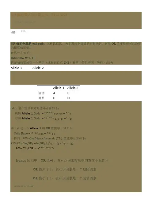
OR值的意义和计算公式,和95% CI(2020-11-18 09:04:51)标签:分类:OR值的全称是odd ratio, 又称比值比,关于发病率很低的疾病来讲,它是OR值即是相对危险度的精准估量值。
计算公式如下:Odd ratio, 95% CI假定咱们要辨别一个基因(或标记位点SNP)有两个等位基因(等位):记为Allele 1Allele 2Allele 1Allele 2病例A B对照C Dodds 值在病例和对照能够计算如下:病例Allele 1Odds = A (A + B)/ B (A + B) = A / B对照Allele 1Odds = C (C + D) / D (C + D) = C / D那么在这一点Allele 1的OR值能够计算如下:Odds Ratio = (A / B)/(C / D) = A D/ B C一样的,95% Confidence Intervals (CIs) 值能够计算如下:95% CI of ln(OR) = ln(OR)±(1/A + 1/B + 1/C + 1/D)95% CI of OR = e95% CI of ln(OR)、logistic回归中,OR值=1,表示该因素对疾病的发生不起作用OR值大于1,表示该因素是一个危险因素OR值小于1,表示该因素是一个爱惜因素同时最好要算出它的95%CIOR为比值比,也称优势比当咱们已知疾病的发生状况,比较疾病组与非疾病组危险因素暴露的情形不同时(即回忆性研究时),用OR进行定量描述。
OR是不是成心义还要看其P值,一样95%CI 上限小于1时说明可能是爱惜因素,相反若是下限大于1那么说明可能是危险因素。
ln(OR)近似服从正态散布,因此在计算OR值置信区间的时候都是先计算ln(OR)置信区间,再计算OR置信区间(参考:,,)参考资料1(维基):概念:Definition in terms of group-wise oddsIf the probabilities of the event in each of the groups are p1(first group) and p2(second group), then the odds ratio is:where q x = 1 −p x. An odds ratio of 1 indicates that the condition or event under study is equally likely to occur in both groups.参考资料2:例子1:例子2:参考资料3:blackwell出版社参考资料4:参考资料5:参考资料6:参考资料7:(介绍了OR和RR区别和联系)OR值的全称是odds ratio、比值比,关于发病率很低的疾病来讲,它是OR值即是相对危险度的精准估量值。
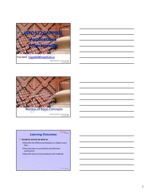
INFO322/IAPP001ApplicationsProgrammingTracy Quick Tracy.Quick@.auReview of Basic ConceptsLearning Outcomes•Students should be able to:Describe the differences between an Object and aClassDescribe how to use default and alternateconstructorsDescribe how to use procedures and methodsIntroduction•Course Outline•Basic ConceptsObject, Class, Abstraction, Encapsulation •Feature Visibility•Additional ConceptsAttributes, Methods•OO ReuseMethodObjectClass•Style GuideCourse OutlineEvent Weighting DueAssignment 1 50%Weeks 6-12Prac Test10%Week 9Exam40%Exam WeekAbout IAPP001•This course is very difficultIt builds on material from IPRG001 & IBRM001It requires you to read material from text books •Missing lectures and tutorials will lead to failure in this course•If you are experiencing difficulties before week 6 –you need to contact me ASAP!!•I am here to help you, but I cant help if you don’t do the workMissing Lectures & Tutorials•If you do miss a lecture you must read the lecture notes and catch up ASAP –contact me if you have difficulties•If you do miss a tutorial you must complete the tutorial work in your own time before the next tutorialEach tutorial builds on material from previoustutorials and in some cases uses solutions fromprevious tutorials as a launch pointIAPP001•You will learn OOP skills and basic architectures •You will need these skills in any IT positionIT managerWeb devSystem designNetwork adminProgrammerEven testers need to understand OOP principles and OOdesign patterns•You must attain basic OOP skills in order to study in second year IT courses at UTS or any other uniPlagiarism•MOSS will be used to detect any misconduct Used by most universities to detect plagiarism inprogramming courses since 1994•DO NOT look at other student’s code, or possess a copy of another student’s code.•Be careful when discussing the assignment with other studentsDiscussing your solution (or approach) withanother student can lead to plagiarismMisconduct •Assignments must only use patterns and API classes covered in this course •Assignments that use other patterns or Java classes will be scrutinised for misconductDon’t try to buy assignments or “get help” fromexternal sources–I will know•All code must be written using BlueJ only Don’t use Eclipse or JBuilder unless you want to bereported for misconduct…Help with Compile & Runtime Errors •Compile errors/jgloss/compileerrormessages.html •Runtime Errors/jgloss/runerrormessages.html •From time to time you will encounter compile errors and runtime errors –it is your responsibility to resolve them. The above URLs are excellent references to help you.•I have also written a small document called “fixing compile errors.doc” which addresses common errors students encounter –it is available on UTSOnlineAssignments•The assignment is your code, it is your responsibility.You must write every line yourself•do not “use” code from the internet•Keep it safe from prying eyes, don’t lend your usb or leave your computer unattended.•Please don’t ask me to pre-mark your assignment or critique your code.•Follow the rules and principles given throughout the course.How to Fail IAPP001•F requently•A bsent (or late)•I n•L ectures (or tutorials)Basic Concepts•Procedural vs Object OrientedProcedural -A series of steps carried out to achievea goal.•Uses functions and procedures to manipulate data.•Input>Process>OutputOO –Objects are manipulated to achieve a goal.•Uses object relationships and interactions toperform tasks•Data belongs to an object and is changed bychanging the object –data is hidden inside theobjectWhy use OO ?•Reusability (reusable components) •Reliability•Robustness•Extensibility•Maintainability•/java/java_oo/node4.shtmlBasic Concepts•ObjectAn object is the building block of 00 programmingAn object can be a tangible thing in the real world •Examples: a pc, a desk, a pen, a studentOr a concept•Example: A student loanIt has attributes (state) and methods (behaviour)•A student has a name (state), a student ID (state), a sex(state)•A student can take notes (behaviour), study (behaviour) An object is a specific entity –the student with ID2113455 is an objectAn object is also an instance of a classBasic Concepts•ClassA class is like a template –a framework.It defines the properties and behaviour of its objects.A student class describes the properties and behaviour of allinstances (objects) of the class ie a student object.•The Student class provides the variables (properties)nameidsexwam•The Student class also provides the functions (behaviour)takeNotes()study()Naming a Class•A class always starts with a Capital Letter eg House, Student, Desk•If a class has a compound name then it is letter cased eg BrickHouse, ComputerDesk, LocalStudent•This allows us to always recognise a class in our code•This is a Java convention and must be followedQuick Quiz•Write down 5 examples of an object•Write down one example of a class•What properties does your class have ?•What behaviour does your class have ?Basic Concepts•Class Features:A class has•constructor(s)-a way to create instances (objects)Class ClassName() –default constructorClass ClassName(arg, arg) –class constructor•attributes–properties which contain an object’s state Type v ariableName•methods –functions which determine an object’sbehaviour using logic eg.ReturnType m ethodName(arg, arg)Type and ReturnType can be int, float, double, boolean,String etcBasic Concepts in OOP•AbstractionAbstraction is the reduction of informationback to a basic concept.A class is an abstraction of an object•EncapsulationEncapsulation is the grouping of data andbehaviour together into distinct bundlesData and behaviour is captured and held(encapsulated) by an object.Encapsulation/Abstraction Example•I have a white Maltese Terror called Billy, he is desexed and is 11 years old.•Billy is an object -encapsulating the following:•State (or data):Name: BillySex: MaleColour: WhiteBreed: Maltese TerrierAge: 11Spade: Yes•Behaviour:Bark –he does lots of this !!!!EatSniffSleep –he does lots of this too !!!Abstraction Example•Here is the abstraction of Billy to the class Dog •Properties:String nameString sexString colourString breedint ageboolean spade•Behaviour:bark()eat()sniff()sleep()Quick Quiz•Using Dog Code Example•What line number(s) contain:The Class nameThe default constructorAnother class constructorThe variable definitions for the classFeature Visibility (Modifiers)•An attribute or method may be Public, Private or Protected.Private features are only visible to the class theybelong to and cannot be inherited.Public features are visible to all classes and can be inherited.Protected features are visible to the class theybelong to and all its subclasses and can beinherited –more later.Additional Concepts•AttributesInstance variables defined by the classHold property states ie data for an objectThe value of an attribute can change for each objectAn attribute is created when the object is created.Its scope is the class: it is visible anywhere in the class.You can initialise the attribute (give it a value) in thedeclaration; if you do not, Java gives it a default value.Attribute declarations are executed before theconstructor.Rule: Naming attributes•An attribute always starts with lowercase eg height, name•A compound name is camelCased eg familyName•Compound names should be used sparingly, most attributes should have a single word name•This is a Java convention and must be followedAdditional Concepts•MethodsFunctions and procedures defined by the classContain repeatable steps to perform a taskMethods define behaviour of the objects of aclassFunctions return values, either by performingcalculations or they can just return the value ofan attributeProcedures are used to change the value of anattributeRule: Naming methods•A method always starts with lowercase eg area(), volume()•A compound name is camelCased eg familyName()•Compound names should be used sparingly, most methods should have a single word name (except accessors & mutators –more later)•This is a Java convention and must be followedQuick Quiz•Using Dog Code Example•How many attributes are there?•How many methods are there?What is the signature of the first method?What is the return type of the first method?Quick Quiz•Using Dog Code Example•How do you create a dog object using the class constructorpublic Dog(String iSex, String iColour, String iBreed, int iAge, boolean iSpade)?•How do you call the bark() method?OO ReuseThere are 3 types of reuse:Method Reuse –a method can be calledwith different variablesObject-based Reuse –an instance of a class(an object) can be created many timesClass-based Reuse –a parent class can beinherited by many child classes –morelaterMethod ReuseA method can be called many timesDog billy = new Dog (“M", "White", "Maltese Terrier", 11, true);System.out.println(billy.sleep());System.out.println(billy.bark());System.out.println(billy.sleep());System.out.println(billy.eat());System.out.println(billy.sleep());•sleep() method reusedObject ReuseMany objects can be created from a class Dog macca = new Dog ("M", "Tan", "Boxer", 4,false);System.out.println(macca.bark());System.out.println(macca.eat());System.out.println(macca.sleep());•macca and billy objects both created fromthe Dog classData Types•So far you have seen a few data types in IPRG001•Primitive data types eg int, double, boolean, char etcThey are maroon in BlueJ, these are keywords •Class data types eg String, Scanner, Double These are classes defined in the API (Java ClassLibrary)When you create a new class in Java, you arecreating a new data type.Classes and Data Types •The class name is the data type of an object •Dog is the data type of the Dog object macca •String is the data type of a String object •Scanner is the data type of a Scanner object •Eg Scanner in = new Scanner(System.in);String entry = in.nextLine();Objects –Review•An object is an instance of a class• A constructor(default and/or class) creates an object of a class•Here is an example of a constructor:public Rental(int id, Customer customer){ … }•It takes an int and a Customer object as parameters •We call it like this:Rental newRental = new Rental(1, newCustomer);•Where newCustomer is a Customer object, created by a Customer constructorAssigning Attributes •Parameters to a constructor usually set the values of attributes for an object•It is done inside the constructorpublic Rental(int id, Customer customer){ this.id = id;this.customer = customer; }•this is a keyword in Java that refers to the current object ie the object with datatype Rental that is being created by the constructorAssigning Attributes•We could have also done thispublic Rental(int newId, Customer newCustomer){id = newId;customer = newCustomer;}•Note: the parameters have different names to the attributes, so we do not need to differentiate between the attribute (of the object) and the constructor parameter.Passing Objects•A variable has a name, type& value•The value can be a primitive type egdouble height = 3.0;•Or a reference type egDog billy = new Dog(“M", "White", "Maltese Terrier", 11, true);•A reference variable is a pointer to an object; the location of the object in memoryMemoryMemory location is hexadecimal (base 16)We don’t normally care what the memory location is, so we draw the value as a pointerMore on pointers•A reference (or pointer) value can be passed as an argument.•If you pass a pointer, then the parameter is the local variable that points to the object•The local variable disappears when the method exits, but the object does not.Arrays revision•In IPRG001 you used arrays to hold multiple elements of a particular data type eg •private String[] names = {“Tracy”, “Beth”};•Or•private String[] names = new String[100];•names[0] = “Tracy”;•Names[1] = “Beth”;•We can use arrays with any defined data typeArray Examplepublic class Kennel {private Dog[] dogs = new Dog[100];private int count = 0;public Kennel(){Dog lilly = new Dog ("F", "White", "Maltese Terrier", 9,true);add(lilly);}public void add(Dog dog){dogs[count] = dog;count++;} }Array Object DiagramThe new object is now pointed to by an entry in the array.The value of the array item is a pointer to the objectStyle Guide•A ClassName starts with a capital letter eg Dog•A constant is capitalised eg RATE• A variable starts with a lowercase eg name• A method name starts with a lowercase eg sleep()•Names should be simple•Use real words not abbreviations•Add useful inline comments to methods, if needed •Attributes, variables and methods are camelCasedeg firstNameHomework•Download the revision exercises from theCourse Documents section on UTSOnline.•Unzip the file and complete the exercises bywriting the required code in the Exercise class.•A sample solution is given in the Solution class, so that you can check how well you did.。

LEC风险评价标准及风险确定准则一、引言LEC(Lowest Effect Concentration)风险评价标准是一种用于评估化学物质对生态系统的潜在风险的方法。
该标准是基于对生物多样性和生态系统功能的保护而制定的,旨在确定化学物质在环境中的最低有效浓度,从而确保生态系统的健康和可持续发展。
二、背景随着化学物质的广泛使用和排放,对其潜在风险的评估变得越来越重要。
传统的风险评估方法主要关注高浓度下的急性毒性,而LEC风险评价标准则更注重低浓度下的慢性毒性效应。
该标准的制定旨在填补现有评估方法的不足,提供更全面、准确的风险评估结果。
三、LEC风险评价标准的主要内容1. LEC风险评价标准的基本原理LEC风险评价标准基于生态学和毒理学的原理,结合化学物质的特性和生态系统的敏感性,确定了一系列评价指标和阈值,用于评估化学物质对生态系统的潜在风险。
2. LEC风险评价标准的评估指标LEC风险评价标准主要包括以下评估指标:- 生物多样性指标:包括物种丰富度、物种多样性指数等,用于评估化学物质对生态系统中不同物种的影响。
- 生态系统功能指标:包括养分循环、能量流动等,用于评估化学物质对生态系统整体功能的影响。
- 生物标志物指标:包括生物体内的生化指标、生理指标等,用于评估化学物质对生物个体的影响。
3. LEC风险评价标准的风险等级划分LEC风险评价标准将化学物质的潜在风险划分为五个等级:极低风险、低风险、中等风险、高风险和极高风险。
根据评估指标的数值和阈值的比较,确定化学物质所属的风险等级。
四、LEC风险评价标准的应用LEC风险评价标准广泛应用于环境监测、风险管理和政策制定等领域。
具体应用包括:1. 环境监测:通过采集环境样品,测定其中化学物质的浓度,并根据LEC风险评价标准进行风险评估,为环境保护和治理提供科学依据。
2. 风险管理:基于LEC风险评价标准,制定合理的风险管理措施,包括减少化学物质的排放、采取适当的处理技术等,以降低生态系统的潜在风险。
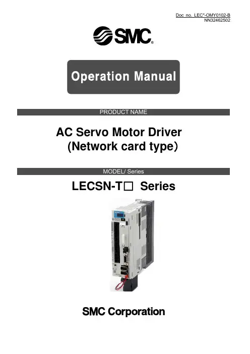
Doc no. LEC*-OMY0102-BNN32462502PRODUCT NAMEAC Servo Motor Driver (Network card type)MODEL/ SeriesLECSN-T□SeriesLECSN2-T□ Series / Driver1. Safety InstructionsThese safety instructions are intended to prevent hazardous situations and/or equipment damage.These instructions indicate the level of potential hazard with the labels of “Caution,” “Warning” or “Danger.”They are all important notes for safety and must be followed in addition to International Standards (ISO/IEC),*1) and other safety regulations.*1) ISO 4414: Pneumatic fluid power -- General rules relating to systemsISO 4413: Hydraulic fluid power -- General rules relating to systemsIEC 60204-1: Safety of machinery -- Electrical equipment of machines (Part 1: General requirements)ISO 10218: Manipulating industrial robots -- Safety.Caution Caution indicates a hazard with a low level of risk which, if not avoided, could result in minor or moderate injury.Warning Warning indicates a hazard with a medium level of risk which, if not avoided, could result in death or serious injury.Danger Danger indicates a hazard with a high level of risk which, if not avoided, will result in death or serious injury.Warning1. The compatibility of the product is the responsibility of the person who designs the equipment or decides its specifications.Since the product specified here is used under various operating conditions, its compatibility with specific equipment must be decided by the person who designs the equipment or decides its specifications based on necessary analysis and test results.The expected performance and safety assurance of the equipment will be the responsibility of the person who has determined its compatibility with the product.This person should also continuously review all specifications of the product referring to its latest catalog information, with a view to giving due consideration to any possibility of equipment failure when configuring the equipment.2. Only personnel with appropriate training should operate machinery and equipment.The product specified here may become unsafe if handled incorrectly.The assembly, operation and maintenance of machines or equipment including our products must be performed by an operator who is appropriately trained and experienced.3. Do not service or attempt to remove product and machinery/equipment until safety is confirmed.The inspection and maintenance of machinery/equipment should only be performed after measures to prevent falling or runaway of the driven objects have been confirmed.When the product is to be removed, confirm that the safety measures as mentioned above are implemented and the power from any appropriate source is cut, and read and understand the specific product precautionsof all relevant products carefully.Before machinery/equipment is restarted, take measures to prevent unexpected operation and malfunction.4. Contact SMC beforehand and take special consideration of safety measures if the product is to be used in any of the following conditions.1) Conditions and environments outside of the given specifications, or use outdoors or in a place exposed todirect sunlight.2) Installation on equipment in conjunction with atomic energy, railways, air navigation, space, shipping,vehicles, military, medical treatment, combustion and recreation, or equipment in contact with food and beverages, emergency stop circuits, clutch and brake circuits in press applications, safety equipment or other applications unsuitable for the standard specifications described in the product catalog.3) An application which could have negative effects on people, property, or animals requiring special safetyanalysis.4) Use in an interlock circuit, which requires the provision of double interlock for possible failure by using amechanical protective function, and periodical checks to confirm proper operation.Note that the CAUTION level may lead to a serious consequence according to conditions. Please follow the instructions of both levels because they are important to personnel safety.What must not be done and what must be done are indicated by the following diagrammatic symbols.In this Instruction Manual, instructions at a lower level than the above, instructions for other functions, and so on are classified into "POINT".After reading this installation guide, always keep it accessible to the operator.LECSN2-T□ Series / Driver1. Safety InstructionsCautionThe product is provided for use in manufacturing industries.The product herein described is basically provided for peaceful use in manufacturing industries.If considering using the product in other industries, consult SMC beforehand and exchange specifications or a contract if necessary.If anything is unclear, contact your nearest sales branch.Limited warranty and Disclaimer/Compliance RequirementsThe product used is subject to the following “Limited warranty and Disclaimer” and “Compliance Requirements”.Read and accept them before using the product.Limited warranty and DisclaimerThe warranty period of the product is 1 year in service or 1.5 years after the product is delivered, whichever is first.*3)Also, the product may have specified durability, running distance or replacement parts. Please consult your nearest sales branch.For any failure or damage reported within the warranty period which is clearly our responsibility, a replacement product or necessary parts will be provided.This limited warranty applies only to our product independently, and not to any other damage incurred due to the failure of the product.Prior to using SMC products, please read and understand the warranty terms and disclaimers noted in the specified catalog for the particular products.*3) Vacuum pads are excluded from this 1 year warranty.A vacuum pad is a consumable part, so it is warranted for a year after it is delivered.Also, even within the warranty period, the wear of a product due to the use of the vacuum pador failure due to the deterioration of rubber material are not covered by the limited warranty.Compliance RequirementsWhen the product is exported, strictly follow the laws required by the Ministry of Economy, Trade and Industry (Foreign Exchange and Foreign Trade Control Law).1. To prevent electric shock, note the followingWARNINGBefore wiring and inspections, turn off the power and wait for 15 minutes or more until the charge lamp turns off. Then, confirm that the voltage between P+ and N- is safe with a voltage tester and others.Otherwise, an electric shock may occur. In addition, when confirming whether the charge lamp is off or not, always confirm it from the front of the driver.Ground the driver and servo motor securely.Any person who is involved in wiring and inspection should be fully competent to do the work.Do not attempt to wire the driver and servo motor until they have been installed. Otherwise, it may cause an electric shock.Do not operate switches with wet hands. Otherwise, it may cause an electric shock.The cables should not be damaged, stressed, loaded, or pinched. Otherwise, it may cause an electric shock.During power-on or operation, do not open the front cover of the s driver. Otherwise, it may cause an electric shock.Do not operate the driver with the front cover removed. High-voltage terminals and charging area are exposed and you may get an electric shock.Except for wiring and periodic inspection, do not remove the front cover of the driver even if the power is off. The driver is charged and you may get an electric shock.To prevent an electric shock, always connect the protective earth (PE) terminal (marked ) of the driver to the protective earth (PE) of the cabinet.To avoid an electric shock, insulate the connections of the power supply terminals.4. Additional instructionsThe following instructions should also be fully noted. Incorrect handling may cause a fault, injury, electric shock, etc.CAUTIONProvide an external emergency stop circuit to ensure that operation can be stopped and power switched off immediately.Do not disassemble, repair, or modify the equipment.Before resetting an alarm, make sure that the run signal of the driver is off in order to prevent a sudden restart. Otherwise, it may cause an accident.Use a noise filter to reduce the effects of electromagnetic interference. Electromagnetic interference may occur on electronic devices used near the driver.Do not burn or disassemble the driver, as toxic gas may be generated.Please dispose a driver, battery (primary battery) and other options according to your local laws and regulations. Please display or notify the final product as necessary.EEP-ROM lifeThe number of write times to the EEP-ROM, which stores parameter settings, etc., is limited to 100,000. If the total number of the following operations exceeds 100,000, the driver may malfunction when the EEP-ROM reaches the end of its useful life.Write to the EEP-ROM due to parameter setting changesWrite to the EEP-ROM due to device changesOrigin setting in absolute position detection systemSTO function of the driverWhen using the STO function of the driver, refer to chapter 13.Compliance with global standardsFor the compliance with global standards, refer to appendix 4.«About the manuals»You must have this Instruction Manual and the following manuals to use this servo. Ensure to prepare them to use the LECSN2-T□ safely.«Wiring»Wires mentioned in this Instruction Manual are selected based on the ambient temperature of 40 °C. «U.S. customary units»U.S. customary units are not shown in this manual. Convert the values if necessary according to the following table.CONTENTS1.1 Summary ............................................................................................................................................. 1-2 1.2 Function block diagram ....................................................................................................................... 1-3 1.3 Driver standard specifications ............................................................................................................. 1-6 1.4 Combinations of driver and servo motors ........................................................................................... 1-7 1.5 Function list ......................................................................................................................................... 1-8 1.6 Model designation ............................................................................................................................. 1-11 1.7 Structure ............................................................................................................................................ 1-14 1.7.1 Parts identification ........................................................................................................................ 1-14 1.8 Installation and removal of network card .......................................................................................... 1-15 1.9 Configuration including peripheral equipment .................................................................................. 1-182.1 Installation direction and clearances ................................................................................................... 2-3 2.2 Keep out foreign materials .................................................................................................................. 2-5 2.3 Encoder cable stress........................................................................................................................... 2-5 2.4 Inspection items .................................................................................................................................. 2-5 2.5 Parts having service lives ................................................................................................................... 2-6 2.6 Restrictions when using this product at altitude exceeding 1000 m and up to 2000 m above sea level ..2-73.1 Input power supply circuit ................................................................................................................... 3-3 3.2 I/O signal connection example ............................................................................................................ 3-6 3.2.1 For sink I/O interface ...................................................................................................................... 3-6 3.2.2 For source I/O interface ................................................................................................................. 3-7 3.3 Explanation of power supply system ................................................................................................... 3-8 3.3.1 Signal explanations ........................................................................................................................ 3-8 3.3.2 Power-on sequence ....................................................................................................................... 3-9 3.3.3 Wiring CNP1, CNP2, and CNP3 .................................................................................................. 3-10 3.4 Connectors and pin assignment ....................................................................................................... 3-12 3.5 Signal (device) explanations ............................................................................................................. 3-14 3.5.1 Input device .................................................................................................................................. 3-14 3.5.2 Output device ............................................................................................................................... 3-16 3.5.3 Output signal ................................................................................................................................ 3-18 3.5.4 Power supply ................................................................................................................................ 3-18 3.6 Forced stop deceleration function ..................................................................................................... 3-19 3.6.1 Forced stop deceleration function ................................................................................................ 3-19 3.6.2 Base circuit shut-off delay time function ...................................................................................... 3-21 3.6.3 Vertical axis freefall prevention function ...................................................................................... 3-22 3.6.4 Residual risks of the forced stop function (EM2) ......................................................................... 3-22 3.7 Alarm occurrence timing chart .......................................................................................................... 3-23 3.7.1 When you use the forced stop deceleration function ................................................................... 3-23 3.7.2 When you do not use the forced stop deceleration function ........................................................ 3-24 3.8 Interfaces .......................................................................................................................................... 3-25 3.8.1 Internal connection diagram ......................................................................................................... 3-253.8.2 Detailed explanation of interfaces ................................................................................................ 3-26 3.8.3 Source I/O interfaces ................................................................................................................... 3-28 3.9 Servo motor with a lock ..................................................................................................................... 3-29 3.9.1 Safety precautions ....................................................................................................................... 3-29 3.9.2 Timing chart .................................................................................................................................. 3-30 3.9.3 Wiring diagrams (LE-□-□series servo motor) .......................................................................... 3-36 3.10 Grounding ....................................................................................................................................... 3-374.1 Switching power on for the first time ................................................................................................... 4-3 4.1.1 Startup procedure .......................................................................................................................... 4-3 4.1.2 Wiring check ................................................................................................................................... 4-4 4.1.3 Surrounding environment ............................................................................................................... 4-5 4.2 Startup ................................................................................................................................................. 4-5 4.3 Switch setting and display of the driver............................................................................................... 4-7 4.3.1 Switches ......................................................................................................................................... 4-7 4.3.2 Scrolling display ............................................................................................................................. 4-8 4.3.3 Status display of an axis .............................................................................................................. 4-10 4.4 Test operation ................................................................................................................................... 4-12 4.5 Test operation mode ......................................................................................................................... 4-12 4.5.1 Test operation mode in Setup software (MR Configurator2TM) .................................................. 4-13 4.5.2 Motor-less operation in upper side ............................................................................................... 4-175.1 Parameter list ...................................................................................................................................... 5-2 5.1.1 Basic setting parameters ([Pr. PA_ _ ]) .......................................................................................... 5-3 5.1.2 Gain/filter setting parameters ([Pr. PB_ _ ]) ................................................................................... 5-4 5.1.3 Extension setting parameters ([Pr. PC_ _ ]) .................................................................................. 5-6 5.1.4 I/O setting parameters ([Pr. PD_ _ ]).............................................................................................. 5-8 5.1.5 I/O Extension setting 2 parameters ([Pr. PE_ _ ]) .......................................................................... 5-9 5.1.6 Extension setting 3 parameters ([Pr. PF_ _ ]) .............................................................................. 5-11 5.1.7 Positioning control parameters ([Pr. PT_ _ ]) ............................................................................... 5-13 5.1.8 Network setting parameters ([Pr. PN_ _ ]) ................................................................................... 5-16 5.2 Detailed list of parameters ................................................................................................................ 5-17 5.2.1 Basic setting parameters ([Pr. PA_ _ ]) ........................................................................................ 5-17 5.2.2 Gain/filter setting parameters ([Pr. PB_ _ ]) ................................................................................. 5-31 5.2.3 Extension setting parameters ([Pr. PC_ _ ]) ................................................................................ 5-44 5.2.4 I/O setting parameters ([Pr. PD_ _ ])............................................................................................ 5-64 5.2.5 Extension setting 2 parameters ([Pr. PE_ _ ]) .............................................................................. 5-68 5.2.6 Extension setting 3 parameters ([Pr. PF_ _ ]) .............................................................................. 5-72 5.2.7 Positioning control parameters ([Pr. PT_ _ ]) ............................................................................... 5-74 5.2.8 Network setting parameters ([Pr. PN_ _ ]) ................................................................................... 5-99 5.3 Software limit ..................................................................................................................................... 5-99 5.4 How to set the electronic gear ........................................................................................................ 5-100 5.4.1 Electronic gear setting in the cyclic synchronous mode, profile mode and point table method 5-100 5.4.2 Electronic gear setting in the indexer method ............................................................................ 5-1026.1 Different adjustment methods ............................................................................................................. 6-2 6.1.1 Adjustment on a single driver ......................................................................................................... 6-2 6.1.2 Adjustment using setup software (MR Configurator2TM) .............................................................. 6-3 6.2 One-touch tuning ................................................................................................................................. 6-4 6.2.1 One-touch tuning flowchart ............................................................................................................ 6-5 6.2.2 Display transition and operation procedure of one-touch tuning ................................................... 6-6 6.2.3 Caution for one-touch tuning ........................................................................................................ 6-11 6.3 Auto tuning ........................................................................................................................................ 6-12 6.3.1 Auto tuning mode ......................................................................................................................... 6-12 6.3.2 Auto tuning mode basis ................................................................................................................ 6-13 6.3.3 Adjustment procedure by auto tuning .......................................................................................... 6-14 6.3.4 Response level setting in auto tuning mode ................................................................................ 6-15 6.4 Manual mode .................................................................................................................................... 6-16 6.5 2gain adjustment mode ..................................................................................................................... 6-207.1 Filter setting ......................................................................................................................................... 7-2 7.1.1 Machine resonance suppression filter ........................................................................................... 7-2 7.1.2 Adaptive filter II............................................................................................................................... 7-5 7.1.3 Shaft resonance suppression filter ................................................................................................. 7-7 7.1.4 Low-pass filter ................................................................................................................................ 7-8 7.1.5 Advanced vibration suppression control II ..................................................................................... 7-8 7.1.6 Command notch filter ................................................................................................................... 7-13 7.2 Gain switching function ..................................................................................................................... 7-14 7.2.1 Applications .................................................................................................................................. 7-14 7.2.2 Function block diagram ................................................................................................................ 7-15 7.2.3 Parameter ..................................................................................................................................... 7-16 7.2.4 Gain switching procedure ............................................................................................................. 7-19 7.3 Tough drive function.......................................................................................................................... 7-23 7.3.1 Vibration tough drive function ....................................................................................................... 7-23 7.3.2 Instantaneous power failure tough drive function ........................................................................ 7-25 7.4 Compliance with SEMI-F47 standard ............................................................................................... 7-29 7.5 Model adaptive control disabled ....................................................................................................... 7-31 7.6 Lost motion compensation function .................................................................................................. 7-32 7.7 Super trace control ............................................................................................................................ 7-358.1 Explanations of the lists ...................................................................................................................... 8-2 8.2 Alarm list ............................................................................................................................................. 8-3 8.3 Warning list ....................................................................................................................................... 8-11 8.4 Remedies for alarms ......................................................................................................................... 8-14 8.5 Remedies for warnings ..................................................................................................................... 8-54 8.6 Troubleshooting at power on ............................................................................................................ 8-65 8.7 Trouble which does not trigger an alarm/warning ............................................................................. 8-669.1 Driver ................................................................................................................................................... 9-2。
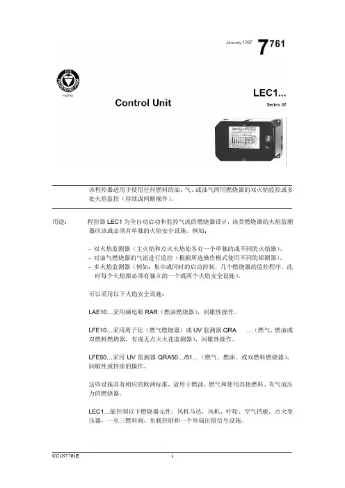
该程控器适用于使用任何燃料的油、气、或油气两用燃烧器的双火焰监控或多处火焰监控(持续或间断操作)。
用途:程控器LEC1为全自动启动和监控气流的燃烧器设计,该类燃烧器的火焰监测器应该或必须有单独的火焰安全设施。
例如:- 双火焰监测器(主火焰和点火火焰处各有一个单独的或不同的火焰器)。
- 对油气燃烧器的气流进行监控(根据所选操作模式使用不同的探测器)。
- 多火焰监测器(例如:集中或同时的启动控制,几个燃烧器的监控程序,此时每个火焰都必须有独立的一个或两个火焰安全设施)。
可以采用以下火焰安全设施:LAE10…采用硒电眼RAR(燃油燃烧器),间歇性操作。
LFE10…采用离子化(燃气燃烧器)或UV监测器QRA …(燃气、燃油或双燃料燃烧器,有或无点火火花监测器),间歇性操作。
LFE50…采用UV监测器QRA50…/51…(燃气、燃油、或双燃料燃烧器),间歇性或持续的操作。
这些设施具有相应的欧洲标准,适用于燃油、燃气和使用其他燃料、有气流压力的燃烧器。
LEC1…能控制以下燃烧器元件:风机马达,风机、叶轮、空气挡板,点火变压器,一至三燃料阀,负载控制和一个外端出错信号设施。
程控器结程控器LEC1…以及火焰监控器LAE10…和LFE10…乃插入式设计,便于安装和构火焰在燃烧器的任何位置,在控制面板上或控制柜里。
空端子底座和框架由防挤压、安全设施:耐热塑料作成。
程控器上由同步马达控制的开关机械部分、继电器以及其他开关、控制、调节元件安装在固态印刷电路板上。
操作:以下是单信号燃烧器启动和监控的操作模式说明:有多个火焰监控的情况下,所有连接到程控器的燃烧器在同一模式下,同时受到操作控制和监控。
如果一台燃烧器因为故障而自锁,将导致所有燃烧器的关闭。
通过对开关的操作,无故障燃烧器将立即重新启动,故障燃烧器的火焰监测器也将运行。
该开关必须同时中断所有通向点火变压器的控制线路和燃料阀。
连接实例,请参考数据页7781。
燃烧器启只有在下列情况下,燃烧器启动:动准备:- 程控器上的机械开关位于启动位置。
lec打分法分级标准(一)LEC打分法分级标准引言LEC打分法(Level of Evidence and Consistency,简称LEC打分法)是用于评估医学研究证据质量的一种常用方法。
通过对研究设计、研究质量和研究结果一系列因素的综合考量,将研究结果分为不同的级别,以指导临床实践和决策制定。
LEC打分法的分类标准根据LEC打分法,研究结果可分为以下五个级别:1.Level I:高水平证据–高质量的随机对照试验(RCT)–系统综述和Meta分析–大规模队列研究–临床决策分析研究2.Level II:中等水平证据–非随机对照试验–小样本随机试验(N<50)–队列研究3.Level III:低水平证据–非随机对照试验–小样本随机试验(N<50)–队列研究4.Level IV:观察性研究–案例对照研究–系列研究–案例报告5.Level V:专家意见–专家意见–个案经验LEC打分法的使用LEC打分法可以帮助医生、研究者和决策者评估研究结果的可靠性和适用性。
在实践中,LEC打分法可用于以下方面:•指导临床实践:根据证据级别,医生可以更准确地判断研究结果的可信度,从而更好地指导临床决策。
•指导研究设计:研究者在进行新的研究时,可参考LEC打分法,选择合适的研究设计和方法,以提高研究的可靠性和有效性。
•支持决策制定:政策制定者、医疗机构和保险公司可以借助LEC打分法评估相关研究,从而做出更科学和合理的决策。
结论LEC打分法作为一种科学且实用的评估方法,在医学研究领域发挥着重要作用。
通过对研究证据进行分级,能够更准确地评估研究结果的可靠性和适用性,为临床实践和决策制定提供科学依据。
因此,医生、研究者和决策者都应熟练掌握LEC打分法,并将其广泛应用于相关领域。
LEC风险评价标准及风险确定准则一、引言LEC(Lowest Effect Concentration)风险评价标准是一种常用的环境风险评价方法,可以用于评估化学物质对环境和生物体的潜在风险。
本文将详细介绍LEC风险评价标准的相关内容,包括标准的定义、应用范围、评价指标和风险确定准则。
二、标准定义LEC风险评价标准是基于化学物质对生物体的毒性效应进行评估的一种方法。
它通过确定对生物体产生最低影响的浓度或剂量来评估风险水平。
LEC值越低,表示化学物质对生物体的毒性越高,风险水平也越高。
三、应用范围LEC风险评价标准主要应用于环境风险评估领域,可以评估化学物质在土壤、水体和空气中的潜在风险。
它可以用于评估化学品的毒性,指导环境管理和决策,保护生态环境和人类健康。
四、评价指标LEC风险评价标准主要包括以下评价指标:1. LEC值:LEC值是评估化学物质对生物体的毒性的关键指标。
它是通过实验测定得出的,表示对生物体产生最低影响的浓度或剂量。
2. 毒性分类:根据LEC值的大小,将化学物质分为不同的毒性等级,如高毒、中毒和低毒等。
这有助于对化学物质的风险进行分类和比较。
3. 风险等级:根据LEC值和毒性分类,将化学物质的风险水平分为不同的等级,如高风险、中风险和低风险等。
这有助于确定风险管理策略和措施。
五、风险确定准则LEC风险评价标准的风险确定准则主要包括以下内容:1. 风险等级划分:根据LEC值和毒性分类,将化学物质的风险水平划分为不同的等级。
例如,LEC值小于1 mg/L的化学物质属于高风险,LEC值在1-10mg/L之间的化学物质属于中风险,LEC值大于10 mg/L的化学物质属于低风险。
2. 风险管理策略:根据风险等级,制定相应的风险管理策略和措施。
对于高风险化学物质,应采取严格的监管措施,限制其使用和排放;对于中风险化学物质,应加强监测和管理,控制其风险;对于低风险化学物质,可以适度放宽管理要求。