电主轴培训教材NEW
- 格式:doc
- 大小:462.50 KB
- 文档页数:44

技术协议甲方:乙方:宁夏小巨人机床有限公司代理方:双方就甲方购买乙方HCN5000ⅡL(壹台)卧式加工中心达成以下技术协议。
一、机床技术规格1.机床特性HCN系列卧式加工中心是 Mazak 公司开发的高性能卧式加工中心。
通过采用高速主轴技术、高速进给技术、高速换刀技术、高速数控系统技术等高端技术,大幅度缩短加工时间,提高加工效率,满足多种生产需要。
1.1 高生产率HCN5000ⅡL加工中心其轴快移速度达到60m/min,轴加速度达0.8G,刀具交换时间为1.5秒,主轴加减速时间为1.48秒(0-12000rpm),托盘交换时间仅7秒,这些指标可以在很大程度上缩短非加工时间,提高加工效率。
标准主轴配置12000rpm、功率30/22KW(30分/连续)电主轴以及电机绕组为双绕组结构,最大扭矩输出可以达到300N.m,可以满足钢件、铸铁件等材料粗、精加工的需要。
机床控制系统采用了世界领先水平的Mazatrol Matrix Nexus数控系统,该数控系统使用了高速的64位RISC CPU,大幅度提高了数控系统的数据处理能力和运动控制性能,并率先采用了个人计算机(PC)与CNC无缝融合的技术,实现了PC和CNC之间的宽带双向通讯,使机床具备了先进的智能化功能。
1.2 高精度利用FEM有限元分析设计确保运动轴在高加减速运动下能够不产生振动,从而确保机床长时间稳定、高精度加工。
通过采用线性导轨技术确保各轴运动的高速度、高精度和高的刚性。
2.机床所有零部件加工、装配成品质量符合产品图纸及相关技术要求。
其安全标准符合GB15760-1995《金属切削机床安全防护通用技术条件》的有关规定。
其精度标准符合ISO 230-1《机床检验通则》以及ISO 10791系列《加工中心检验条件》的有关规定。
4. HCN5000ⅡL卧式加工中心标准主机技术规格参数表5、HCN5000ⅡL卧式加工中心机床配置ABC、标准技术文件二、设备验收机床验收分预验收和终验收。
轴承知识培训教材——修理办事公司一、轴承差不多轴承的种类:(一)滚动轴承和滑动轴承:1、滚动轴承:深沟球轴承、角接触球轴承、短圆柱滚子轴承、球面滚子轴承(双列调心滚子轴承)、(双列)调心球轴承、圆锥滚子轴承、滚针轴承、球面滚子推力轴承、推力球轴承、CARB轴承、圆柱滚子推力轴承、滚针推力轴承、四点接触球轴承、圆锥滚子推力轴承、Y-轴承、角接触推力球轴承、交叉圆柱滚子轴承、交叉圆锥滚子轴承、反转展转支撑轴承2、滑动轴承:关节轴承、杆端关节轴承、自润滑轴承、青铜轴承。
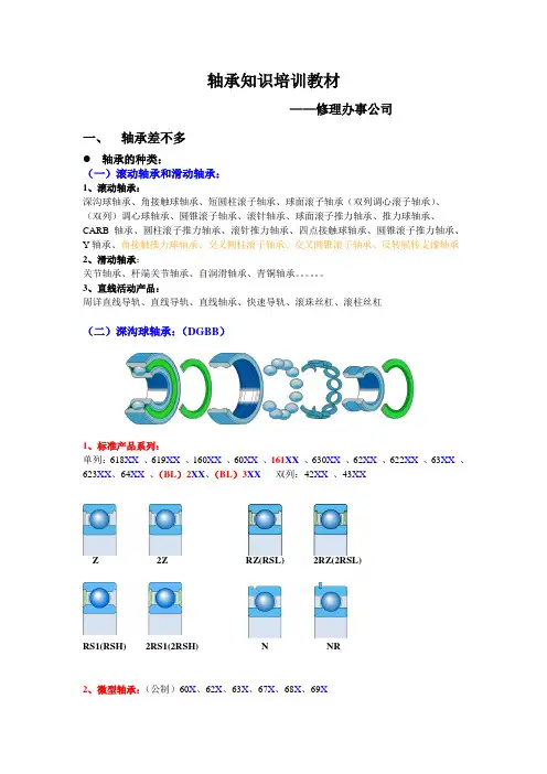
3、直线活动产品:周详直线导轨、直线导轨、直线轴承、快速导轨、滚珠丝杠、滚柱丝杠(二)深沟球轴承:(DGBB)1、标准产品系列:单列:618XX、619XX、160XX、60XX 、161XX、630XX、62XX、622XX、63XX、623XX、64XX、(BL)2XX、(BL)3XX双列:42XX、43XXZ 2Z RZ(RSL) 2RZ(2RSL)RS1(RSH) 2RS1(2RSH) N NR2、微型轴承:(公制)60X、62X、63X、67X、68X、69X(英制)3、防尘盖及密封:(1)防尘盖:SKF:Z、2Z FAG:ZR、2ZRNTN、NSK、KOYO:Z、ZZ NACHI:ZE、2ZE(2)密封:标准密封圈的材料为晴橡胶(NBR)其他材料:聚丙烯合成橡胶(ACM)、氟塑料合成橡胶(FKM)、硅树脂接触式密封:SKF:RS1(RSH)、2RS1(2RSH)…….橡胶密封圈带钢板加强,工温度-40℃到+120℃RS2、2RS2………………………..橡胶密封圈带钢板加强,工作温度-60℃到+180℃FAG:RSR、2RSRNTN:LU、LLU NSK:DU、DDUKOYO:RS、2RS (超轻)RD、2RD NACHI:NSE、2NSE非接触式密封:具衬钢板合成橡胶的低摩擦密封,可遭受温度-40℃至+120℃SKF:RZ(RSL)、2RZ(2RSL)FAG:RSD、2RSDNTN:LB、LLB NSK:V、VVKOYO:RU、2RU NACHI:NKE、2NKE4、保持架:冲压型模注型机削型后缀:无后缀TN9 M,MA,MB 材料:1) 钢玻璃纤维加强聚酰胺6,6 黄铜工作温度:取决于轴承其他零件-50℃到+120℃取决于轴承其他零件速度:60000 随保持架体的宽度和是冲压保持架速度(n x dm)max 2) 运转温度而变 1.5-2.0倍 3)注:1)少数轴承采取冲压铜保持架,用后缀”Y”表示3)转速增高才能还取决于工作和情形前提(负荷、2) n x dm=转速X轴承平均直径润滑、相邻部件和冷却等)以及轴承的构造钢保持架聚酰胺保持架黄铜保持架5、后缀:A:内部设计经改进。
・电主轴技术讲座・Seminar on Motorized Spindle第二讲 电主轴的基本参数与结构(二)Lesson ⅡMain Specifications and Struc ture of Motorized Spindle (Ⅱ)周延 李中行5 润滑 滚动轴承在高速回转时,正确的润滑极为重要,稍有不慎,将会造成轴承因过热而烧坏。
当前电主轴主要有两种润滑方式。
(1)油脂润滑 是一次性永久润滑,不需任何附加装置和特别维护。
但其温升较高,允许轴承工作的最高转速较低,一般d m n 值在110×106以下。
在使用混合轴承条件下,其d m n 值可以提高25%~35%。
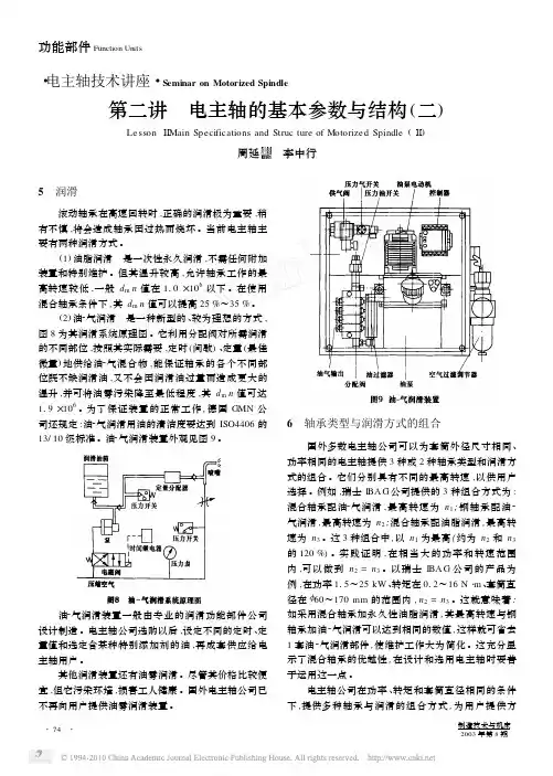
(2)油2气润滑 是一种新型的、较为理想的方式,图8为其润滑系统原理图。
它利用分配阀对所需润滑的不同部位,按照其实际需要,定时(间歇)、定量(最佳微量)地供给油2气混合物,能保证轴承的各个不同部位既不缺润滑油,又不会因润滑油过量而造成更大的温升,并可将油雾污染降至最低程度,其d m n 值可达119×106。
为了保证装置的正常工作,德国GMN 公司还规定:油2气润滑用油的清洁度要达到ISO4406的13/10级标准。
油2气润滑装置外观见图9。
油2气润滑装置一般由专业的润滑功能部件公司设计制造。
电主轴公司选购以后,设定不同的定时、定量值和选定含某种特别添加剂的油,再成套供应给电主轴用户。
其他润滑装置还有油雾润滑。
尽管其价格比较便宜,但它污染环境,损害工人健康。
国外电主轴公司已不再向用户提供油雾润滑装置。
6 轴承类型与润滑方式的组合 国外多数电主轴公司可以为套筒外径尺寸相同、功率相同的电主轴提供3种或2种轴承类型和润滑方式的组合。
它们分别具有不同的最高转速,以供用户选择。
例如,瑞士IBA G 公司提供的3种组合方式为:混合轴承配油2气润滑,最高转速为n 1;钢轴承配油2气润滑,最高转速为n 2;混合轴承配油脂润滑,最高转速为n 3。
GMN Paul Müller Industrie GmbH & Co. KGSPINDELTECHNIK Original operating and assembly manualGMN oil-air-lubrication devicePRELUB GP…GMN Operating and assembly manual 106 02 02PRELUB GP / 2013-10GMN Operating and assembly manual 106 02 02 2 Table of contents1Basic notes ..................................................................................................3 2Safety information........................................................................................7 3Mode of operation........................................................................................9 4Transport and storage................................................................................10 5Device description......................................................................................11 6Assembly manual.......................................................................................17 7Start-up......................................................................................................21 8Operation...................................................................................................27 8.1Operational mode.......................................................................................27 8.2Malfunctionen.............................................................................................30 8.3Shut-down..................................................................................................32 9Maintenance ..............................................................................................33 10Disposal.....................................................................................................34 11Technical data............................................................................................35 12 Enclosure (36)12.1 Dimensional drawing (36)12.2 Electric connection (37)12.3 Lubrication scheme (38)12.4 Spare part list and drawing (41)12.5 Control plan (43)PRELUB GP / 2013-10GMN Operating and assembly manual 106 02 02 31 Basic notesUse in accordance with the regulationsThe oil-air-lubrication device is only allowed for industrial use. The oil-air-lubrication device is for delivering the lubricating oil ac-cording to the specification.The oil-air-lubrication device may only be put into operation if it isinstalled in or at another machine and if it is operated together withthe machine.The oil-air-lubrication device may only be used according to thetechnical data (see chapter …technical data“).High-handed structural changes at the oil-air-lubrication device arenot permitted.For damages at machines and persons resulting from that, we donot assume liability.This also belongs to a use in accordance with the regulations:∙ Pay attention to all notes in the operating manual.∙ Carry out all maintenance work.∙ Follow all appropriate regulations for the work safety and accident prevention during all life cycles of the oil-air-lubrication device.∙ Having the required professional education and authorization of your company to carry out the necessary works at the oil-air-lubricating device.Another use or a use beyond can not be considered to be in accordance with the regulations.PRELUB GP / 2013-10GMN Operating and assembly manual 106 02 02 4 Obligation of the operator The operator carries the responsibility for the correct installation, operation and maintenance of the oil-air-lubrication device by qualified and trained staff accord-ing to the manual’s details.In addition to this he is responsible to use the oil-air-lubrication device only in accordance with the regulations.∙ If hot or cold machine parts lead to danger, the customer must se-cure them from being touched. The guards on "moving parts" mustnot be removed.∙ Remove leakages of dangerous material to be conveyed such that people or the environment are not endangered∙ Comply with legal regulations.∙ Eliminate any danger due to electrical energy.∙ A safety data sheet for the current used lubricating oil of oil-air-lubrication device must be provided.Scope of guaranteeGuarantee regarding operational safety, reliability and capacity can only be granted by the manufacturer under the following conditions:∙ Assembly, connection, construction, maintenance and repair are carried out by professional staff.∙ The oil-air-lubrication device is used according to the manual’s details espe-cially to the use in accordance with the regulations.∙ The limiting values, mentioned in the technical data, must not be exceeded in any case.∙ Retrofitting and repair works at the oil-air-lubrication device, may only be done by GMN.All guarantees and warranties expire for damages to central lubri-cation systems that are caused by operation with improper lubri-cating oil (e.g. piston wear, piston jamming, pluggings, embrittledsealings). We do not assume liability on damages caused by lubri-cating oils, even if these lubricants have been tested and releasedby laboratory tests, as damages caused by lubricants (e.g. by ex-pired or improper stored lubricating oils, batch variations etc.) cannot be retraced to their root cause in retrospect.PRELUB GP / 2013-10GMN Operating and assembly manual 106 02 02 5Emphasises Please pay attention, not only to the safety instructions under this main point, but also to those special security advices which are inserted on the other pages.This symbol warns of electrical voltage.Safety instructions which, if not complied with, may endanger per-sons, are marked specifically with the general hazard symbol.This heading is used if inaccurate compliance or non-compliance with the operating instructions or specified work proceduresetc.may result in damage of the device or men.Points out special information!PRELUB GP / 2013-10GMN Operating and assembly manual 106 02 02 6 Manufacturer of oil-air-lubrication deviceSales and ServicePRELUB GP / 2013-10GMN Operating and assembly manual 106 02 02 72 Safety informationBasic notes regarding the construction, operation and maintenance are listed as follows. This operating manual absolutely must be read before assembly and start-up, by the mechanics as well as by the specialist staff/operator.In addition to this, it must be permanently available at the site.Notes attached directly at the machine, must strictly be followed and held into completely readable condition!Qualification and training of the personnelThe operating, maintenance, inspection and assembly personnel must have appropriate qualifications for this work. The operator must pre-cisely regulate the personnel's areas of responsibility and monitor them. If the personnel do not have the necessary knowledge, they must be trained and instructed. The operator must ensure that the personnel have completely understood the contents of the user information.Danger due to non-observance of the safety informationNot observing the safety information can lead to people, the environ-ment and the machines being endangered.Not observing the safety information can lead to the loss of any and all claims for damages. In individual cases, non-observance can, forexample, lead to the following dangers :∙ Failure of important plant functions∙ Failure of prescribed methods of maintenance and preventive main-tenance∙ Endangering people due to electrical, mechanical and chemical ef-fects∙ Endangering the environment due to leakages of dangerous materi-alsPRELUB GP / 2013-10GMN Operating and assembly manual 106 02 02 8 Safety information for maintenance, inspection and assembly workAll maintenance, inspection and assembly work may only be carried out by trained specialists who have been informed appropriately by studying the user information closely.All work must only be carried out when the plant is at a standstill and pressure less and free from tension. Always wear appropriate protec-tive clothing (e.g. safety goggles). Always comply with the procedures for bringing the plant to a standstill that are described in the operating manual.All the safety and protective equipment must be replaced immediately after com-pleting work. Media that are a threat to the environment must be disposed of in accordance with pertinent official specifications.Secure the system during maintenance and repair works, against intentional or unintentional reoperation.Dispose of process materials in accordance with the safety data sheets of the lu-bricant manufacturer.Alterations and manufacture of spare parts without authorityRebuilding and alterations to the plant are only allowed after consulta-tion with the manufacturer. Original manufacturer spares and manu-facturer/authorized accessories are for safety purposes. Using other parts may lead to liability for the consequences being invalidated. The manufacturer does not assume liability or claims for damages for as-sembly, retrofitted by the operator.Inadmissible methods of operationOperational security of the system is only guaranteed if it is operated in accor-dance with the operating instructions . The limit values stated in the technical data must not be exceeded under any circumstances.General risk referenceAll components of the oil-air-lubrication device are lent according to the prevailing regulations of the construction of technical machines in re-gards to the operational safety and accident prevention. Independently of this, the use can lead to dangers fort the user respectively third per-sons or other technical facilities. The oil-air-lubrication device therefore may fulfil only in technically fault-free condition its intended use. This may only be carried out under compliance of the safety regulations and the attention of the operating manual.Therefore please observe regularly the unit and its assembly and check it for possible damages or leakages .PRELUB GP / 2013-103 Mode of operationDescriptionThe oil-air-lubrication device is based on the fact that an exact metered oil drop is transported by air into the lubrication line and a lubricating film coats the complete lubricating line. With this procedure the lube point is supplied with oil continu-ously.The oil supply is done in time intervals by the single line unit. The exact oil measurement into the air stream of the individual outlet is done by the measuring valve. The air stream can be adjusted via the adjusting throttles for every outlet.FunctionThe oil air lubrication device supplies lubricating oils according to the specification.As soon as the device control of the gear pump starts to operate it for a pump pulse, oil is supplied to the oil metering valves in the connected oil mixing distribu-tor. The integrated pressure limiting valve limits the line pressure to 30 bar.During this pressure build-up and the following pressure hold time lubricant is ap-plied onto the connected lube points via the installed oil metering valves.The metering oil reaches the non-return valve and flows into the mixing chamber.Then lubricant is supplied to the lube points by the connected lubrication line and via a regulated air stream.When switching off the pump, the pressure relief valve opens so that oil pressure is reduced to a residual pressure in the connected main line network.After the break time is processed a new lubrication cycle begins.If the air throttle is completely closed a new oil lubrication is carried out.Device versionThe oil air lubrication device can be designed with or without installed oil-air mixing distributor:∙ PRELUB GP 0:Without installed oil-air mixing distributor. In this case theoil air lubrication unit has one outlet for oil and one for air.You can connected external oil-air mixing distributors tothis outlets.∙ PRELUB GP 2: With installed oil-air mixing distributor, 2 lube point connec-tions.∙ PRELUB GP 4: With installed oil-air mixing distributor, 4 lube point connec-tionsGMN Operating and assembly manual 106 02 02 9PRELUB GP / 2013-10GMN Operating and assembly manual 106 02 02 10 Operation with reduced air inlet pressure The mentioned standard device versions are designed for an operation pressure of 6 bar. In special cases these devices can also be operated with a compressed air with lower pressure. The compressed air source must, in any case, offer a min. pressure of 4 bar .Prerequesite for the operation with reduced air inlet pres-sure is that the necessary lubricant pressure is definitelyreached according to the operating manual for the machinespindle!Further notes see chapter 7 …start-up“.General notes∙ The oil-air lubrication device sends an error signal in case of a malfunction (oil supply, compressed air supply). This must result in switching off the machine spindle in order to avoid damages.∙ The quantity of lubricating oil for the lube point must be calculated and applied according to the details of the spindle manufacturer.∙ When correcting the adjustment of the oil/air mixing distributor, the transporting air leaves the bearing point almost oil free.∙ Check all lubricating points within short intervals for a correct lubrication during the first operating hours.∙ If necessary correct the air consumption or pulsing of the oil-air lubrication device.4 Transport and storageUse suitable lifting devices for the transport. Do not throw or shock the device. The storage place shall be cool and dry to avoid corrosion of the individual parts. Transport the oil-air lubrication device only when it is empty.Observe the valid safety- and accident prevention regulations. Wear appropriate protection clothes. Keep distance to suspending loads.5 Device descriptionVersion GP 0Connecting blockFilter entityLevel switchMotor gear pumpPressure switch for oil 20 barPressure switch for air 4,5 barLubricant connection or air-and oil connection (number and type depend on device typeFilling socket for lubricating oilPressureconnection G1/4 ManometerOil reservoirOil drain screw Control unitHARTING plugFixing linkVersion GP 2 and GP 4Gear pumpThe gear pump is supplied with voltage in selectable time intervals and lubricating oil flows towards the oil-air mixing distributor. Oil-air-mixing distributorIn the oil air mixing distributor the supplied lubricating oil is metered and conducted to the continuous air flow to get transported to the lubrication outlets of the oil-air mixing distributor.The oil-air mixing distributor can be equipped with two (PRELUB GP 2) or four (PRELUB GP 4) lubrication outlets. Those are independently and individual adjust-able.The oil metering volume per lubrication outlet and the pump pulse depend on the installed oil-air mixing distributor a pprox. 10 mm³ or 30 mm³, compare the details with the type plate.Closing the air-core choke completely, a pure oil lubrication is done. Pay also attention to chapter 7 …adjustment of air supply“.If the pressure sensor for air of the oil-air-mixing distributor sends a malfunction, there is not enough air pressure.Oil-air mixing distri-butor(version 2 or 4 outlets)Filter entity Ventilation block with feedbackLevel switchMotor gear pumpPressure Switch for oil 20 barPressure Switch for air 4,5 barExternal oil-air mixing distributorThe external oil-air mixing distributor is used together with the device version PRELUB GP 0.The external oil-air mixing distributor is available with two or four outlets. They can be adjusted separate.The oil-metering volume per lubrication outlet and pulse is approx.. 10 mm³ or 30 mm³.Closing the air-core choke completely, a pure oil lubrication is done.Pay also attention to chapter 7 article …adjustment of airsupply“. Filling level switchThe filling level switch is for monitoring the oil level in the reservoir and it protects the oil-air-lubrication device and the lubricated machine from damages resulting from lack of lubrication oil. As soon as the switch contact sends a signal (pre-warning) lubrication oil should be refilled to ensure the lubrication procedure. After the switch contact sends a signal, up to 950 lubrication cycles can be carried out (adjustment via the control menu), until the oil-air-lubrication device signals a malfunction.Ventilation block (only for PRELUB GP 2 and PRELUB GP 4)The ventilation block serves for ventilation as described under chapter 8.1 “ventilation operation“.The ventilation block is not installed in the oil-air lubrication device PRELUB GP 0.Lubrication outletOil connectionAir connectionAir throttleOil reservoirThe oil reservoir has a total capacity of approx. 2,7 liter. In order to change the oil, use the oil drain screw. When the level switch sends a signal (prewarning) approx. 1,2 liter of lubrication oil must be refilled.Compressed air maintenance unitThe compressed air maintenance unit consists of the following components.∙Air filter, filter fineness 5 µm∙compressed air control valve∙ solenoid valve∙ manometerThe air filter cleans compressed air from dirt, pipe sinter, rust and condensed water. We recommend to filter the compressed air of the oil-air lubrication device with 25 to 50 µm to ensure a suitable stand time of the filter cartridge. Condensed water of the air filter is collected in the water separator. Drain it via the drain screw. For this purpose switch off voltage and compressed air.The operating air pressure is controlled at the compressed air control valve. The pressure is necessary for the operation of the oil-air lubrication device.The solenoid valve closes when the device is switched off (voltage interrupted) and if an error message is send. Hence it can be avoid that the lubrication lines are blown dry due to the available air flow.The operating air pressure can be set at the compressed air control valve of the manometer (device front). It has to have at least 4,5 bar as otherwise the air pressure switch of the oil-air mixing distributor sends a fault message.In certain cases the operating pressure may have a lower value (see chapter 6).Air filterFilter fineness 5µmAir supplyOperatingair lineSolenoidvalveCompressedair controlvalveWater trapLubricating oil filterThe lubricating oil filter filters the oil. If the filter is dirty, the oil pressure after the filter falls. The installed oil pressure switch sends a fault message. Exchange filter insert, see chapter 9 …maintenance“.Control unitWith the control, unit the system operation canbe monitored and controlled.It has a keyboard and a display. Regarding de-tails for remedy, please see item 8.2 “malfunc-tions”.Adjustment of the several parameters can bedone via the keyboards. With the control planyou can see how to get to the parameter whichshould be adjusted.The buttons “up” and “down” are for selecting themenu items as well as for enter the values in themenu.The buttons “left” and “right” are for the cursor’s movement. The button “se-lect/enter” confirms an entry. With the button “ESC” the menu is left.Parameter of the control unitThe following parameter can be adjusted at the control unit:Parameter Option State of delivery Language ChinesetraditionalChinese simplifiedGermanEnglishFrenchItalianJapaneseSpanishGermanLevel impuls counter 1 - 999 950Lubrication time in sec. 5 - 9 5Break time (hh.mm.ss) 00.00.03 – 09.59.59 00.03.00ImpulsVentilation operation1 - 99 1Lubrication timeVentilation operation insec.not adjustable 20Break timeVentilation operation insec.not adjustable 2Pre-lubrication impulse 0 - 99 10Lubrication timePre-lubrication operationin sec.5 - 9 5Break timePre-lubrication operationin sec.2 - 9 8Stand-by operation ON insec.0 - 59 30Stand –by operation OFFin sec.0 - 59 5Monitoring time stand-byoperation in hours0 - 99 4The individual parameters have to be coordinated with the lubricated ma-chine/machine spindle. In chapter 11.5 “control unit plan”, the pictures show how to get to the different parameter.Some parameter can only be changed when entering a password. The authorized access of GMN differs from the user authorization.In certain cases the parameter can be set for a specific machine /machine spindle. In this case the details regarding the deliverycondition of above mentioned table are not valid.6 Assembly manualThe following conditions have to be satisfied during the assembly of theoil-air-lubrication device, thus it can be assembled with other parts to acomplete machine without affect the safety and health of human:∙Set up the oil-air-lubrication device on both sides at the place where it has to be installed. Pay also attention to the mentioned data regarding the fastening bore in the dimensional drawing. (chapter 12.1).∙Use the already installed securing straps at the housing for the assembly.∙The installation location has to be free from vibrations and shocks.∙The oil-air-lubrication device must not be installed on movable machine parts. Pneumatic (Compressed air supply)∙The pressure in the compressed air system has to have min. 6 bar!The device can be operated also with reduced air inlet pressure. The switch point of the air pressure switch must be changed for this purpose. Notes for the operation with reduced air pressure and the setting of the switch point can be found in chapter 7 “start-up”. Remove the sealing cap and assemble a suitable hose fitting.∙The compressed air connection of the oil-air-lubrication device has an internal thread G ¼. Remove the sealing cap and assemble a proper hose fitting.∙Internal diameter of the connection hose: min. 8 mm∙Commercial compressed air lines can be used for the compressed air supply!∙The filter fineness of the installed compressed air maintenance unit in the oil-air lubrication device has 5 µ. The compressed air that is lead into the oil-air lubri-cation unit shall be dry and prefiltered with 25 to 50 µm to ensure a proper stand time of the filter cartridge.∙Other requirements regarding the compressed air quality (oil concentration etc.) can be found in the assembly and operating manual of the machine spindle or the lube point. The compressed air for the oil-air lubrication device must already there fulfil the requirements.∙Take care that the pipe lines are clean!∙Assemble the pipe lines professional and free from distortion!Lubrication line assembly (PRELUB GP 2 and PRELUB GP 4)The installed oil-air mixing distributor hast two and four outlets (depends on cus-tomer request) for polyamide pipe Ø6x1 mm or Ø4x0,85 mm, depends on meter-ing volume of oil-air mixing distributor.∙Remove the sealing cap from the lubrication line connection and assemble the polyamide pipe.∙Use only transparent polyamide pipe acc. to DIN 73378 (plastic pipes with tol-erated outside diameter, transparent plastic pipes enable a visual control of the oil transport)!∙The line length between oil-air mixing distributor and the lube point shall be between 0,5 m to 5 m. The minimum length is necessary that the lubrication oil that is fed into the air flow can build a constant oil flow. Lubrication lines with a length of over 5 m need a longer waiting time until a complete application with lubricating oil.∙In case the distance between the oil-air mixing distributor and the lubrication point is smaller than 0,5 m or larger than 3 m, GMN recommends to use coils (4 to 5 coils) near the lubrication point. The lubrication oil that is collected in the coil after the system is switched off, will immediately be available at the lube point (e.g. spindle bearing) at the reactivation.∙Observe that all pipe lines are clean.∙Assemble the pipe line professional and free from distortion!∙If not all lubrication line connections are necessary at the oil-air mixing distribu-tor the according lubricant outlets can be closed:- Close the air throttles of the outlets that need to be closed.- If necessary pull out lubrication lines from the outlet fittings.- Close lubricant outlets with a suitable sealing plug.Assembly of external oil-air mixing distributor (PRELUB GP 0)The device version PRELUB GP 2 and PRELUB GP 4 have the air ducts and the oil lines between lubrication pump and oil-air mixing distributor already assembled in the device cabinet.The oil-air mixing distributor for the version PRELUB GP 0 (also various) are in-stalled outside the device cabinet. The connections for the air and the oil lines to-wards the oil-air mixing distributor are on the left side of the device cabinet:G1/4∙ Compressed air: Thread∙Oil: Hydraulic fitting for pipe outside ø 6 mmLines between oil-air lubrication unit and external oil-air mixing distributor.∙Compressed air ductInternal diameter: min. 8 mm∙Oil pressure lineLine quality: High pressure line (pump pressure 30 bar).Line length: max. 30 m.∙We recommend to assemble the oil air mixing distributor in a way that they are higher than the compressed air- or oil pressure connection of the oil-air lubrica-tion unit. The last oil-air mixing distributor in the main line must be equipped with a ventilation unit and shall be installed at the highest point. This is for a bet-ter ventilation of the lubrication oil line. If the recommended assembly of the oil-air mixing distributor is not possible, the correct ventilation of the lubrication oil line must be ensured by more and/or longer pump cycls.Ventilation unit∙The order of more oil-air mixing distributors is done in a row. Never connect more than 8 lubrication outlets to one oil-air lubrication device. The oil-air mix-ing distributor with two and four lubrication outlets can be combined as re-quested.∙When connecting the lubrication line to the hydraulic fitting of the external oil-air mixing distributor, use the delivered sleeves to support the polyamide pipe.∙The installation position of the individual oil-air mixing distributor shall be ob-served as shown on the pictures.Correct Correct Correct Wrong∙Furthermore please observe the assembly notes regarding the lubrication lines or for closing non-used lubricant outlets regarding the versions PRELUB GP 2 and PRELUB GP 4 in above mentioned section “lubricant line assembly (PRE-LUB GP 2 und PRELUB GP 4)”.Current supplyThe electric connection should only be done by a professional electrician!The oil-air lubrication unit is connected at the 10 pole Harting plug at the device box.∙Connect the oil-air lubrication device professional according to theenclosed connection plan.∙Attention! The existing mains voltage has to match with the neces-sary supply voltage (see type plate)!7 Start-upFilling with lubricating oilFill up the lubricating oil reservoir with clean lubricating oil via the filling connection until the max. level is received! Receiving a signal by the level switch (Prewarn-ing), refill approx. 1.2 liter lubricating oil according to the specification.Do not overfill!∙ When selecting the lubricating oil also observe the operating manual of the lu-bricated machine / machine spindle.∙ The oil-air lubrication device is equipped with an oil fine filter. In order to enlarge the stand time of the installed filte cartridge we recommend to fill in cleaned lu-brication oil∙ Pay attention to the lubricating oil manufacturers safety data sheet!∙ The lubricating oil viscosity range changes with the operating temperature!∙ Check the oil level regularly during the first operating hours, and refill clean lu-bricant if necessary!If the parameter …prelubrication“ is set with 1 or higher, the oil-air lubrication unit always, starts after it is connected to voltage , witha prelubrication . Please also read therefore the paragraph inchapter 8.1 “pre-lubrication”.Starting the oil-air-lubrication device∙ Make sure that all supply lines are correctly connected.∙ Set the operating pressure at the compressed air maintenance unit.Standard device: 5 barAt reduced operating pressure: 3,5 bar min.∙ The oil-air lubrication device has no ON/OFF switch.∙ The oil-air-lubrication device operates in the pre-lubrication mode.。
电主轴修理电主轴是用于内表面磨削的一种高速旋转的高精度的专用部件,主轴装配质量的好坏直接影响轴承加工质量。
因此,电主轴的修理是一项技术要求很高的工作。
必须认真进行轴承测振,检查配研隔垫,预负荷的施加和零件的清洗工作。
应具有一个良好的工作场地,它必须光线充足,环境清洁,装有空调和吸尘设备。
装配人员进入工作场地更换工作服和拖鞋,非工作人员不得到装配间随便走动。
修理前应仔细阅读说明书,读懂图纸。
修理过程主要包括拆、轴承配对、清洗、装配和试车等。
(一)、拆卸使用工具主要有:内六角扳手、呆扳手、两脚活动扳手和主轴修架、主轴顶杆等专用工具。
1、把待修电主轴放在专用主轴修架上,使用六角扳手卸下主轴前端盖和前主轴压盖和主轴后端盖;2、用呆扳手固定转轴,用两角活动扳手从转轴上卸松后轴承左旋压紧螺帽;3、使用主轴专用顶杆把转子连同后支承轴承和套筒等到组件从前往后压出;4、从前轴承室卸下前轴承及隔环。
注意:拆卸过程不能有任何硬性敲击现象,必须使用工具按部就班拆卸,否则将损坏主轴零件,同时拆卸压紧螺帽应注意其旋向。
(二)、轴承配对主轴使用轴承一般都为C级向心推力角接触球轴承,主轴的转轴都要求承受较大的负荷和具有较高的刚性,因此一般都安装配对轴承。
由于轴承零件加工精度误差一般都在4-5µ M用选择装配法装配出来的轴承,还不能达到装配主轴的要求,这些轴承必须经过测振,测量内外径和检查接触角,轴承振动值不能超过规定值。
在没有测振仪器时,只好凭借经验在轴承清洗好后,用手旋转听声音来辨别(严禁在没有润滑的情况下反复多次转动),其测法如下:合格的轴承:在汽油缸内带油转动,声音清脆,无明显节奏音和震感。
不合格的轴承:在汽油缸内带油转动,声音沉闷,有较强的节奏音和小震感。
电主轴和皮带轴的主轴轴承多半是成对使用,两套轴承的内外径和接触角的尺寸,我们一般要求双联轴承内、外径相互差值不大于1µ M(0.001MM),并为同一出厂批次。
常用机床的电气控制培训教材(1)常用机床的电气控制培训教材
第一部分:机床的电气控制基础知识
1. 电气控制的定义和分类
2. 电气元器件的基本原理及特点
3. 基本电路分析及信号处理
4. 电气控制系统的组成及特点
第二部分:机床电气控制的主要内容
1. 伺服控制系统的原理及应用
2. PLC控制系统的原理及应用
3. 数控系统的原理及应用
4. 机床电控系统集成技术
第三部分:机床电气控制系统的应用案例
1. 机床主轴驱动控制系统
2. 液压系统的电气控制
3. 门式加工中心电气控制系统
4. 五轴加工中心的电气控制系统
第四部分:机床电气控制系统的维护和故障排除
1. 电气元器件的维护及更换
2. 电气控制系统的故障排除方法
3. 机床电控系统日常维护要点
4. 常见故障案例分析及解决方法
第五部分:机床电气控制系统的发展趋势
1. 智能控制技术的应用
2. 云制造与机器人技术的发展
3. 新材料、新工艺、新技术在机床电气控制中的应用
4. 未来机床电气控制系统的发展方向
本教材结合实际应用,立足于机床电气控制的基础知识,重点讲授机床电气控制系统的主要内容和应用案例,以及维护和故障排除方法等方面的知识,适合广大机床工程师参考学习。
同时,对机床电气控制系统发展趋势进行了简要介绍,帮助学员们对未来机床电气控制系统的发展方向有一个初步了解。


·64··电主轴技术讲座·Seminar on Motorized Spindle第二讲!电主轴的基本参数与结构(一)LessonⅡMain Specifications and Structure of the Motorized SpindIe(l)周延祐李中行1 电主轴的基本参数电主轴的基本参数和主要规格包括:套筒直径、最高转速、输出功率、计算转速、计算转速转矩和刀具接口等。
其中计算转速又称额定转速,是指恒转矩驱动与恒功率驱动的交汇点,参见图1和图2。
它相当于图2中的A点,即小于计算转速时为恒转矩驱动,大于计算转速时为恒功率驱动。
计算转速转矩为转速小于和等于计算转速的转矩。
一般电主轴型号中含有套筒直径、最高转速和输出功率这3个参数。
表1列出了德国GMN公司用于加工中心和铣床的电主轴的型号和主要规格。
表1 德国GMN公司用于加工中心和铣床的电主轴的型号和主要规格主要型号套筒直径/mm最高转速/(r/min)输出功率/kW计算转速/(r/min)计算转速转矩/N·m润滑刀具接口HC120-42000/11120420001130000 3.5OL SK30HC120-50000/11120500001130000 3.5OL HSK-E25HC120-60000/5.512060000 5.5600000.9OL HSK-E25 HCS150g-18000/9150180009750011G HSK-A50 HCS170-24000/2717024000271800014OL HSK-A63HC170-40000/6017040000604000014OL HSK-A50/E50 HCS170g-15000/151701500015600024G HSK-A63 HCS170g-20000/1817020000181200014G HSK-F63 HCS180-30000/1618030000161500010OL HSK-A50/E50 HCS185g-8000/11185800011213053G HSK-A63 HCS200-18000/152001800015180080OL HSK-A63 HCS200-30000/1520030000151200012OL HSK-A50”E50 HCS200-36000/162003600016600029OL HSK-A50”E50 HCS200-36000/7620036000762500029OL HSK-A50”E50 HCS200-182000/152001200015180080G SK40HCS230-18000/152301800015180080OL HSK-A63 HCS230-18000/252301800025300080OL HSK-A63 HCS230-24000/182302400018315057OL HSK-A63 HCS230-24000/452302400045750058OL HSK-A63 HCS230-182000/222301200022240087G HSK-A63 HCS230-182000/252301200025300080G HSK-A63 HCS232-185000/9230150009122070G HSK-A63 HCS275-20000/6027520000601000057OL HSK-A63 HCS285-12000/3228512000321000306OL HSK-A100 HCS300-12000/3030012000301000286OL HSK-A100 HCS300-14000/2530014000251100217OL HSK-A63 HCS300-8000/303008000301000286G HSK-A100注:HCS—矢量驱动;OL—油气润滑;G—永久油脂润滑;SK—ISO锥度。
高速加工中心电主轴结构设计及关键技术应用The construction design and key technology applicationOf motor spindle which used in high-speed machining centres作者姓名学位类型工科硕士学科、专业机械工程研究方向机械工程导师及职称2008年9月1合肥工业大学本论文经答辩委员会全体委员审查,确认符合合肥工业大学硕士学位论文质量要求。
答辩委员会签名:(工作单位、职称)主席:委员:导师:2独创性声明本人声明所呈交的学位论文是本人在导师指导下进行的研究工作及取得的研究成果。
据我所知,除了文中特别加以标志和致谢的地方外,论文中不包含其他人已经发表或撰写过的研究成果,也不包含为获得合肥工业大学或其他教育机构的学位或证书而使用过的材料。
与我一同工作的同志对本研究所做的任何贡献均己在论文中作了明确的说明并表示谢意。
学位论文作者签字:签字日期:年月日学位论文版权使用授权书本学位论文作者完全了解合肥工业大学有关保留、使用学位论文的规定,有权保留并向国家有关部门或机构送交论文的复印件和磁盘,允许论文被查阅或借阅。
本人授权合肥工业大学可以将学位论文的全部或部分论文内容编入有关数据库进行检索,可以采用影印、缩印或扫描等复制手段保存、汇编学位论文。
(保密的学位论文在解密后适用本授权书)学位论文者签名导师签名签字日期:年月日签字日期:年月日学位论文作者毕业后去向:工作单位电话通讯地址: 邮编3高速加工中心电主轴结构设计、关键技术及应用摘要现代汽车制造技术引入柔性化时代,高速加工中心成为了发动机柔性化生产线的重要组成部分,高速加工大大提高了生产率、加工精度、加工质量,并降低成本。
而高速电主轴是高速加工中心核心部件,因而对高速加工中心电主轴结构设计、关键技术及应用进行分析具有十分重大意义。
本文首先针对加工中心高速电主轴的介绍了其结构特点、附件设计等,对两种不同的电主轴进行结构分析,主轴与转子的配合设计的方法;附件是电主轴重要组成部分,直接影响到电主轴使用性能。
接着,重点论述了高速电主轴的关键技术,如:电主轴热稳定分析、轴承的润滑技术、动平衡设计、驱动技术等。
本文对高速电主轴重要组成部分角接触陶瓷球轴承进行了重点论述,尤其是详细分析了轴承的预紧力。
最后,结合本人工作,介绍电主轴的维护与维修,其中对脂润滑的电主轴装配做了详细介绍。
关键词:高速加工电主轴附件设计轴承维护与维修4The construction design and key technology application Of motor spindle which used in high-speed machining centresAbstractKey words:5致谢本论文是在导师韩江教授关心和指导下完成的,从论文课题的选定到方案的确立,以及对文章的详细审定无不倾注了他的心血和辛劳。
特别是在他担任繁重的校务领导工作的情况下,依然在百忙中不忘抽出宝贵的时间给予我很多的支持和帮助。
他那种强烈的事业心和高度的责任感,将激励我在今后的工作学习中不断努力进取。
在此,特别向韩老师表示衷心的感谢和诚挚的敬意。
论文课题的选定、方案的确立和论文撰写过程中还得到了奇瑞汽发动机公司刘伟总经理助理,王德义副总工程师,朱晓曦电气工程师等同志的大力支持和悉心指导,也得到同事们的帮助,促进了我技术的迅速提高。
在此,向他们表示衷心的感谢。
同时,感谢我的家人,在论文研究和编撰过程中给我的帮助与支持,使我无论面临什么困难都能充满自信。
最后感谢合肥工业大学,为我提供了这样一个学习及科研的环境,使我能够掌握丰富的专业知识,具备了一名硕士研究生应有的素质,并顺利地完成了研究课题及硕士论文。
再一次对曾经给我帮助的所有人和将要在论文答辩中给予我帮助老师表示深深地感谢!王二镇2008年10月6目录第一章绪论 (1)1.1 课题研究背景及主要内容 (1)1.1.1课题来源 (1)1.1.2课题意义 (1)1.2 高速加工与电主轴 (1)1.2.1高速加工概述 (1)1.2.2电主轴概述 (1)1.2.3电主轴技术的发展及现状 (1)本章小结 (4)第二章高速加工中心电主轴的结构设计及性能分析 (5)2.1 电主轴的性能分析 (1)2.1.1精度和静刚度 (1)2.1.2临界速度 (1)2.1.3残余动不平衡值及验收振动速度值 (1)2.1.4噪音与套筒的温升值 (1)2.1.5使用寿命值 (1)2.1.6电主轴与刀具接口 (1)2.2 电主轴结构设计与分析 (1)2.2.1电主轴结构 (1)2.2.2轴壳和转轴 (1)2.2.3主轴与电机转子的配合 (1)2.3 电主轴附件设计 (1)2.3.1电主轴刀具松夹刀系统 (1)2.3.2内置编码器 (1)2.3.3刀具内冷装置 (1)2.3.4主轴的气吹和气密封 (1)2.3.5松夹刀信号检测 (1)本章小结 (4)第三章电主轴设计制造的几个关键技术问题3.1电主轴的热稳定分析 (1)3.2轴承的润滑技术 (1)3.2.1油脂润滑 (1)3.2.2油雾润滑 (1)3.2.3油-气润滑 (1)3.3动平衡设计 (1)73.4驱动技术 (1)本章小结 (4)第四章高速电主轴的角接触陶瓷球轴承的性能分析 (1)4.1磁悬浮轴承与动静压轴承 (1)4.1.1磁悬浮轴承 (1)4.1.2动静压轴承 (1)4.2混合陶瓷球轴承 (1)4.2.1混合陶瓷球轴承的概述 (1)4.2.1选择混合陶瓷球轴承的理由公式 (1)4.2混合陶瓷球轴承 (1)4.2.2角接触陶瓷球轴承的支承方式 (1)4.2.2混合陶瓷球轴承的装配预加载荷 (1)本章小结 (4)第五章高速电主轴电主轴的维护与维5.1电主轴的维护 (1)5.1.1周保养 (1)5.1.2月保养 (1)5.1.4蝶形弹簧的涨紧力检查 (1)5.2电主轴的易损件的更换步骤与常见故障分析 (1)5.2.1更换刀具夹紧组件步骤 (1)5.2.2更换旋转接头步骤 (1)5.2.3轴承装配的步骤 (1)本章小结 (4)8图2-1 轴向刚度和径向刚度的测量位置 (1)图2-2 临界速度 (1)图2-3 电主轴装配图 (1)图2-4 主轴附件结构图 (1)图2-5 松夹刀油缸 (1)图2-6 刀具内冷冷却液 (1)图2-7 电主轴气吹和气密封 (1)图2-8 模拟量检测传感器 (1)图3-1 冷却系统 (1)表3-1轴承润滑方式性能对比表 (1)表3-2 FAG电主轴轴承润滑脂性能 (1)表3-3 轴承供油量与轴承内径的关系 (1)图3-2 油-气润滑 (1)图3-3 磁悬浮轴承原理 (1)9第一章绪论1.1课题研究背景及主要内容1.1.1课题来源本课题来自于奇瑞汽车股份有限公司发动机公司设备部关于成立电主轴维修间的一个项目。
1.1.2课题意义大约一个世纪以来,组合机床自动线以其高效率统治了汽车工业的生产。
随着竞争加剧,汽车产品更新换代周期从几十年缩短到4年,组合机床自动线由于缺乏柔性而无法适应。
20世纪80年代,美国汽车巨人福特与机床巨人INGERSOLL合作,研制了集高柔性与高效率于一身的高速加工中心,由它组成的柔性自动生产线问世,加快了汽车产品的更新换代,提高了企业的效率和灵活性。
近年来,我国汽车工业采用了大量的数控设备,轿车装备整体上进入了柔性化时代。
发动机是汽车的心脏一样,发动机制造技术汽车制造技术的集中体现。
汽车面世以来。
发动机制造技术已经经历了两次革命。
第一次革命发生在二十世纪初,美国福特汽车公司创始人福特发明了大量生产流水线。
其主要方式,是由组合/专用机床(special purpose machine/Transfer machine)组成的自动生产线TL(Transfer Line),也称为传统自动线。
其最大的优点是高生产率——几十甚至上百把刀同时加工,其效率是任何其它类型生产线无法比拟的;低价格——特别是我国,组合专机价格甚至低于批量生产的通用数控机床。
其最大的缺点是柔性差,一旦产品变型和更换品种即基本上无法使用。
为了解决产品的变型生产和便于更换品种,柔性生产技术被引进了汽车生产。
二十世纪九十年代出现了高转速、高快移速度、高加速度、快速换刀的高速加工中心。
由其组成了高速柔性生产线FTL(Flexible Transfer Line)是发动机制造的第二次革命。
其突出特点是一定程度克服了高柔性和低效率的矛盾。
这种生产线不仅可以加工同样产品范围内的零件,而且可以可以加工变型产品、换代产品以及新产品,真正具备了柔性的意义。
缺点是投资大,效率受局限。
目前是我国轿车企业的热点生产线。
奇瑞汽车股份有限公司自从2003年来,发动机生产线进入了柔性化时代,从国外引进了将近20条柔性生产线。
这些柔性生产线是高速加工中心和相应的辅机,再上加智能工具而组成。
对高速加工中心主要要求是:高速度、高精度、高精度保持性——高机床工程能力指数(cm/cmk),高可靠性等。
高速加工中心的机床指标范围是:快移速度:60~100m/min,加速度:10.6~1.5g;主轴最高转速:8000~15000r/min。
定位精度/重复定位精度——工作台1 m以下,8μm/4μm,工作台1m以上,10μm/5μm(VDI标准)。
主轴从启动到最高转速(或相反)只用1~2s的时间,工作台的加(减)速度要达到(1~10)g(g=9.81m/s2)。
目前,国际上这类加工中心的最新发展是,主运动普遍采用电主轴,进给运动愈来愈多采用直线电机。
同时,普遍运用模块化设计,机床非常简约,外购件(配套件)比例增加,交货期大大缩短。
奇瑞发动机公司目前在这些柔性生产线上,共有各类加工中心350台,这些高速加工中心,主运动普遍采用电主轴。
因此,使用了近260根电主轴。
电主轴作为高速加工中心最关键部件,其性能好坏在很大程度上决定了整台高速机床的加工精度和生产效率,电主轴在国外研究工作开展较早,现在已进入实际应用阶段。
但是,我国电主轴的设计制造技术刚刚起步,电主轴的各项性能指标和国外尚有较大的差距,对国外电主轴缺乏核心技术资料,后期的维护保养与维修工作还在摸索的过程中。
在购买设备时,电主轴厂家要求,高速电主轴6000小时就要进行保养,部分厂家还要求2-3万小时需要更换轴承(脂润滑方式的电主轴),以确保主轴的寿命和精度。
鉴于以上,奇瑞汽车股份有限公司发动机公司设备部做出了成立电主轴维修间的决定,本课题的研究对奇瑞公司乃至国内同行以后更好的使用与维护电主轴,使其创造最大的经济效益具有着非常重大的意义。
1.2高速加工与电主轴1.2.3高速加工概述高速加工技术是指采用超硬材料刀具磨具和能可靠的实现高速运动的高精度、高自动化、高柔性的制造设备,一大幅度的提高切削速度来达到提高材料切除率、加工精度和加工质量的现代制造加工技术。