Zhaga于近日发布LED射灯模块接口规范Book2
- 格式:pdf
- 大小:356.53 KB
- 文档页数:1

Zhaga标准解读真明丽集团封装研发中心赵玉喜Zhaga是新一代LED光引擎介面的规范,由全球照明大厂合作组成的Zhaga联盟所发起,推动LED介面的标准化,有助于LED照明产品的普及。
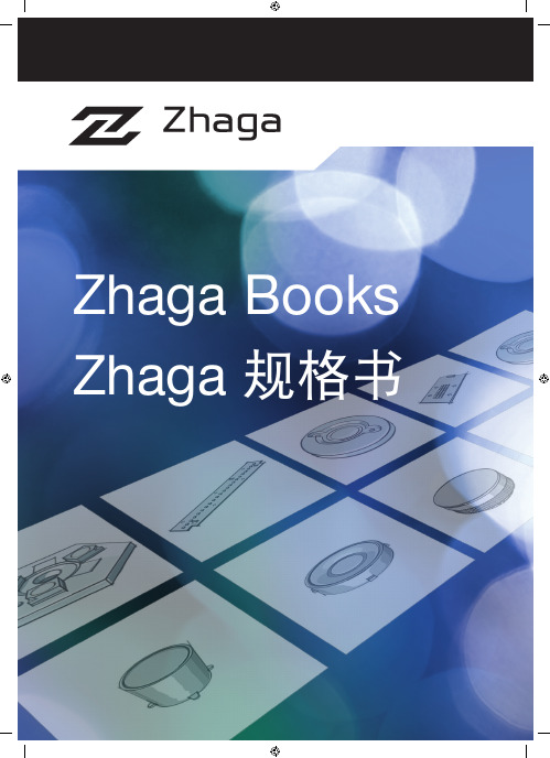
Zhaga规格书概況:规格书1(Book 1): 一般定义和介面本规范在对各个Zhaga介面规范中均涉及的内容进行定义,例如:■一般定义■独立电子驱动与控制装置的机械介面■一般散热介面规格书2(Book 2): 自带电子驱动与控制装置的插座式筒灯光引擎2011年2月,Zhaga联盟通过了第一个光引擎规范。
这一规范中详细描述了筒灯的光引擎介面。
目前这一规范仅供联盟会员使用。
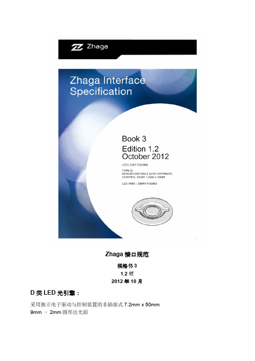
Book2 PHILIPS Fortimo TwistablePHILIPS规格书3(Book 3): 采用独立电子驱动与控制装置的射灯光引擎2011年6月,Zhaga联盟通过了第二个光引擎规范。
这一规范是针对射灯光引擎的介面制定的:Book 3PHILIPS Fortimo SLM Lexel LED SLM Lexel LED SLM 800 25W / RGB规格书4(Book4): 采用独立电子驱动与控制装置的路灯光引擎2012年3月,Zhaga联盟通过了关于采用独立电子驱动与控制装置的平面出光路灯光引擎规范。
Book 4 PHILIPS Fortimo LED HBMt规格书5(Book 5): 采用独立电子驱动与控制装置的插座式LED光引擎2011年9月,Zhaga联盟通过了第三个光引擎规范。
这一规范对插座式光引擎的介面进行了详细描述,光引擎采用的是独立的电子驱动与控制装置。
Book5规格书6(Book6): 自带电子驱动与控制装置的紧凑型插座式LED 光引擎2011年11月,Zhaga联盟通过了第四个光引擎规范,在这一规范中对插座式光引擎的介面进行了详细描述。
Book6 TOSHIBA规格书7: 采用独立电子驱动与控制装置的室内照明光引擎2012年4月,Zhaga联盟通过了一系列采用不同外比例的室内灯光引擎规范。
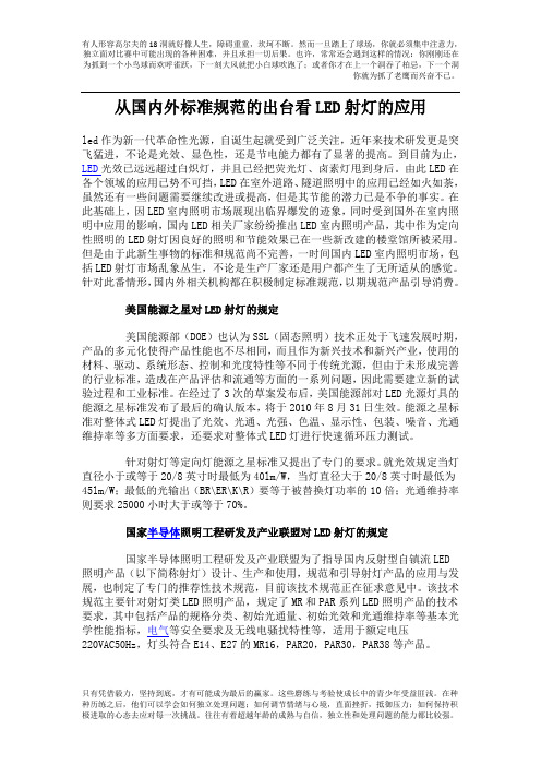
从国内外标准规范的出台看LED射灯的应用led作为新一代革命性光源,自诞生起就受到广泛关注,近年来技术研发更是突飞猛进,不论是光效、显色性,还是节电能力都有了显著的提高。
到目前为止,LED光效已远远超过白炽灯,并且已经把荧光灯、卤素灯甩到身后。
由此LED在各个领域的应用已势不可挡,LED在室外道路、隧道照明中的应用已经如火如荼,虽然还有一些问题需要继续改进或提高,但是其节能的潜力已是不争的事实。
在此基础上,因LED室内照明市场展现出临界爆发的迹象,同时受到国外在室内照明中应用的影响,国内LED相关厂家纷纷推出LED室内照明产品,其中作为定向性照明的LED射灯因良好的照明和节能效果已在一些新改建的楼堂馆所被采用。
但是由于此新生事物的标准和规范尚不完善,一时间国内LED室内照明市场,包括LED射灯市场乱象丛生,不论是生产厂家还是用户都产生了无所适从的感觉。
针对此番情形,国内外相关机构都在积极制定标准规范,以期规范产品引导消费。
美国能源之星对LED射灯的规定美国能源部(DOE)也认为SSL(固态照明)技术正处于飞速发展时期,产品的多元化使得产品性能也不尽相同,而且作为新兴技术和新兴产业,使用的材料、驱动、系统形态、控制和光度特性等不同于传统光源,但由于未形成完善的行业标准,造成在产品评估和流通等方面的一系列问题,因此需要建立新的试验过程和工业标准。
在经过了3次的草案发布后,美国能源部对LED光源灯具的能源之星标准发布了最后的确认版本,将于2010年8月31日生效。
能源之星标准对整体式LED灯提出了光效、光通、光强、色温、显示性、包装、噪音、光通维持率等多方面要求,还要求对整体式LED灯进行快速循环压力测试。
针对射灯等定向灯能源之星标准又提出了专门的要求。
就光效规定当灯直径小于或等于20/8英寸时最低为40lm/W,当灯直径大于20/8英寸时最低为45lm/W;最低的光输出(BR\ER\K\R)要等于被替换灯功率的10倍;光通维持率则要求25000小时大于或等于70%。
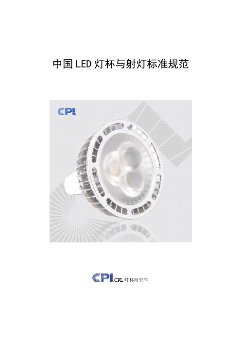
中国LED灯杯与射灯标准规范CPL灯杯研究室LED作为新一代革命性光源,自诞生起就受到广泛关注,近年来技术研发更是突飞猛进,不论是光效、显色性,还是节电能力都有了显著的提高。
到目前为止,LED光效已远远超过白炽灯,并且已经把荧光灯、卤素灯甩到身后。
由此LED在各个领域的应用已势不可挡,LED在室外道路、隧道照明中的应用已经如火如荼,虽然还有一些问题需要继续改进或提高,但是其节能的潜力已是不争的事实。
在此基础上,因LED室内照明市场展现出临界爆发的迹象,同时受到国外在室内照明中应用的影响,国内LED相关厂家纷纷推出LED室内照明产品,其中作为定向性照明的LED射灯因良好的照明和节能效果已在一些新改建的楼堂馆所被采用。
但是由于此新生事物的标准和规范尚不完善,一时间国内LED室内照明市场,包括LED射灯市场乱象丛生,不论是生产厂家还是用户都产生了无所适从的感觉。
针对此番情形,国内外相关机构都在积极制定标准规范,以期规范产品引导消费。
5.1美国能源部对LED射灯的规定美国能源部(DOE)也认为SSL(固态照明)技术正处于飞速发展时期,产品的多元化使得产品性能也不尽相同,而且作为新兴技术和新兴产业,使用的材料、驱动、系统形态、控制和光度特性等不同于传统光源,但由于未形成完善的行业标准,造成在产品评估和流通等方面的一系列问题,因此需要建立新的试验过程和工业标准。
在经过了3次的草案发布后,美国能源部对LED光源灯具的能源之星标准发布了最后的确认版本,将于2010年8月31日生效。
能源之星标准对整体式LED灯提出了光效、光通、光强、色温、显示性、包装、噪音、光通维持率等多方面要求,还要求对整体式LED灯进行快速循环压力测试。
针对射灯等定向灯能源之星标准又提出了专门的要求。
就光效规定当灯直径小于或等于20/8英寸时最低为40lm/W,当灯直径大于20/8英寸时最低为45lm/W;最低的光输出(BR\ER\K\R)要等于被替换灯功率的10倍;光通维持率则要求25000小时大于或等于70%。
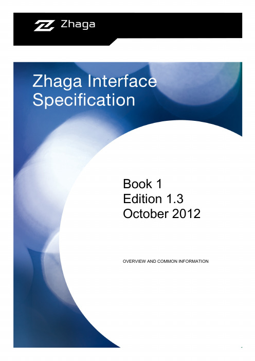
Book 1 Edition 1.3 October 2012 OVERVIEW AND COMMON INFORMATIONZhaga Interface Specification Book 1Summary (informative)BackgroundThe Zhaga Consortium is a worldwide organization that aims to standardize LED light engines.The Zhaga Interface Specification consists of a series of books, which have been approved by the general assembly of the Zhaga Consortium. Each book defines a LED light engine by means of its mechanical, photometric, electrical, thermal, and control interfaces to a luminaire. This makes the LED light engines interchangeable in the sense that is easy to replace one LED light engine with another, even if they have been made by different manufacturers.Each LED light engine belongs to one of the following categories:Type A: socketable with integrated electronic control gear.Type B: socketable with separate electronic control gear.Type C: non-socketable with integrated electronic control gear.Type D: non-socketable with separate electronic control gear.ContentsThis book 1 of the Zhaga Interface Specification is a special book, because it does not define a LED light engine. Instead, this book gives an overview of the Zhaga terminology as well as common information that aims to explain the general aspects of the five interfaces.This book also defines a set of generic compliance tests, which are used to verify if a LED light engine (and a corresponding luminaire) meets the requirements defined in the other books of the Zhaga Interface Specification.The Zhaga Interface Specification does not define the interface between a LED light engine and a separate electronic control gear (type B and D). However, this book defines the physical dimensions of the set of housings that are permitted for such electronic control gear.Intended UseThis book should be read to become familiar with the basic principles of the Zhaga Interface Specification. In particular, the other books of the Zhaga Interface Specification rely on the information provided in this book. This information is not duplicated in those other books.ConformanceAll provisions in the Zhaga Interface Specification are mandatory, unless specifically indicated as recommended, optional or informative.Zhaga Interface SpecificationBook 1: Overview and CommonInformationEdition 1.3July 2012COPYRIGHTThe Zhaga Interface Specification is published by the Zhaga Consortium, and has been prepared by the members of the Zhaga Consortium. All rights are reserved. Reproduction in whole or in part is prohibited without express and prior written permission of the Zhaga Consortium. DISCLAIMERThe information contained herein is believed to be accurate as of the date of publication. However, neither the Zhaga Consortium, nor any member of the Zhaga Consortium will be liable for any damages, including indirect or consequential, from use of the Zhaga Interface Specification or reliance on the accuracy of this document.CLASSIFICATIONThe information contained in this document is for public use.NOTICEFor any further explanation of the contents of this document, or in case of any perceived inconsistency or ambiguity of interpretation, visit or contact info@.Table of Contents1 General (6)1.1 Introduction (6)1.2 Scope (6)1.3 Conformance and References (7)1.3.1 Conformance (7)1.3.2 Normative references (7)1.3.3 Informative references (7)1.4 Common definitions (7)1.5 Common acronyms (9)1.6 Common symbols (9)1.7 Common conventions (10)1.7.1 Cross references (10)1.7.2 Informative text (10)1.7.3 Terms in capitals (10)1.7.4 Units of physical quantities (10)1.7.5 Decimal separator (10)2 Overview of Zhaga (informative) (11)2.1 About Zhaga (11)2.2 Zhaga product certification (11)2.3 Zhaga building blocks and interfaces (11)2.4 Compatibility and Interchangeability (13)2.5 Product Data Set (14)2.6 Compliance testing (15)2.6.1 Initial compliance test (15)2.6.2 Market surveillance (17)2.7 Compatibility check (17)3 Mechanical interface (18)3.1 Drawing principles (18)3.2 Mechanical interface between separated ECG and Luminaire. (18)3.2.1 ECG provisions for both “existing common practice” and “new Zhaga specification” (18)3.2.2 Additional provisions for ECGs according to “existing common practice” (19)3.2.3 Additional provisions for ECGs according to “new Zhaga specification” (20)4 Photometric interface (21)4.1 Light Emitting Surface (21)4.2 Operating conditions for measuring photometric parameters (21)4.3 Luminous flux (22)4.4 Luminous intensity distribution (22)4.5 Luminance uniformity (23)4.6 Correlated color temperature (CCT) (24)Zhaga Interface SpecificationBook 1: Overview and Common InformationTable of Contents Edition 1.3 4.7 Color rendering index (CRI) (24)4.8 Luminaire Optics (informative) (24)5 Electrical interface (25)5.1 Electrical insulation (25)6 Thermal interface (26)6.1 Background information (informative) (26)6.2 Generic thermal interface model (26)6.2.1 General case (26)6.2.2 Test Fixture TPTF (28)6.2.3 Rated Operating Temperature and safety (informative) (29)6.2.4 Thermal overload protected LED Light Engine (29)6.2.5 Ambient temperature (29)6.2.6 Luminaires with multiple LLE’s or multiple LED Modules (29)6.2.7 Thermal compatibility check (30)6.2.8 Thermal uniformity (31)6.2.9 Thermal Interface Material (31)6.2.10 Surface planarity and roughness (32)6.2.11 Aging of LED Light Engine (informative) (32)6.2.12 Influence of the Electronic Control Gear on the thermal interface (informative) (32)7 Control interface (33)Annex A Compliance tests (34)A.1 LLE compliance tests (34)A.1.1 LLE mechanical interface tests (34)A.1.2 LLE photometric interface tests (34)A.1.3 LLE thermal interface tests (37)A.1.4 LLE electrical interface tests (42)A.1.5 LLE Product Data Set test (42)A.2 Luminaire compliance tests (42)A.2.1 Luminaire mechanical interface tests (42)A.2.2 Luminaire photometric interface tests (42)A.2.2 Luminaire thermal interface tests (42)A.2.3 Luminaire electrical interface tests (42)A.2.4 Luminaire Product Data Set test (43)Annex B Product data (44)B.1 Mechanical interface (44)B.1.1 LLE product data related to the mechanical interface (44)B.1.2 Luminaire product data related to the mechanical interface (44)B.2 Photometric interface (44)B.2.1 LLE product data related to photometric interface (44)B.2.2 Luminaire product data related to the photometric interface (44)B.3 Electrical interface (44)B.4 Thermal interface (44)B.4.1 LLE product data related to the thermal interface (44)B.4.2 Luminaire product data related to the thermal interface (45)Annex C Dimensions of the Electronic Control Gear (46)C.1 “Existing common practice” (46)Zhaga Interface SpecificationBook 1: Overview and Common InformationEdition 1.3 Table of ContentsC.1.1 Built-in Electronic Control Gear (46)C.1.2 Independent Electronic Control Gear (55)C.2 “New Zhaga specification” (57)C.2.1 Built-in Electronic Control Gear (57)Zhaga Interface SpecificationBook 1: Overview and Common InformationTable of Contents Edition 1.3 List of FiguresFigure 2-1: Schematic overview of a Luminaire and one or more LED Light Engines (12)Figure 2-2: Schematic overview of a LED Light Engine with integrated ECG (13)Figure 2-3: Schematic overview of a LED Light Engine with separate ECG (13)Figure 2-4: An LLE being Compatible with a Luminaire (14)Figure 2-5: LLE-A being interchangeable with LLE-B (14)Figure 2-6: Overview of test and certification of Zhaga products (16)Figure 2-7: Compatibility check (17)Figure 3-1: Definition of dimensions of ECG mechanical interface (19)Figure 4-1: Rotationally symmetric solid angle bounded by the polar angles γ1 and γ2 which is used to define the Relative Partial Luminous Flux (23)Figure 6-1: Thermal model of a LLE-Luminaire combination (27)Figure 6-2: Power conversion (28)Figure 6-3: Configuration with TIM being part of the LLE (32)Figure A-1: Heat sensor equipment with Test Fixture and LLE under test (38)Figure A-2: Calibration of the heat flux measurement setup. (39)Figure A-3: Position of measurement point for the Reference Temperature (42)Figure C-1: Reference drawing for compact built-in type 1 ECG. (47)Figure C-2: Reference drawing for compact built-in type 2 ECG. (48)Figure C-3: Reference drawing for compact built-in type 8 ECG. (49)Figure C-4: Reference drawing for compact built-in type 9 ECG. (50)Figure C-5: Reference drawing for compact built-in type 3 ECG. (51)Figure C-6: Reference drawing for stretched built-in type 4 ECG (53)Figure C-7: Reference drawing for stretched built-in type 5 ECG (54)Figure C-8: Reference drawing for compact Independent type 6 ECG. (55)Figure C-9: Reference drawing for compact Independent type 7 ECG. (56)Zhaga Interface SpecificationBook 1: Overview and Common InformationEdition 1.3 Table of Contents List of TablesTable 3-1: Designation of ECG housings according to “new Zhaga specification” (20)Table 4-1: Luminous flux categories (22)Table 4-2: Beam angle categories with corresponding minimum and maximum beam angle values. (23)Table C-1: Designation and dimensions for compact Built-in ECGs (46)Table C-2: Designation and dimensions for stretched built-in ECGs (52)Table C-3: Designation and dimensions for compact Independent ECGs (55)Table C-4: Designation and dimensions for stretched Independent ECGs (56)Table C-5: Designation and dimensions for compact Built-in ECGs of “new Zhaga specification” (57)Table C-6: Designation and dimensions for stretched built-in ECGs of “new Zhaga specification” (58)Zhaga Interface SpecificationBook 1: Overview and Common Information1 General Edition 1.3 1 General1.1 IntroductionThe Zhaga Consortium is a worldwide organization that aims to define LED Light Engines, which are interchangeable in the sense that LED Light Engines designed by different manufacturers can be exchanged without complications1. A LED Light Engine (LLE) is a light source for general lighting that is based on solid state technology, and typically consists of one or more LEDs combined with stabilization and control electronics (Electronic Control Gear).Different types of LED Light Engines and corresponding Luminaires are defined in different books of the Zhaga Interface Specification. Each book defines at least the following set of interfaces between the LED Light Engine and the Luminaire:•Mechanical interface•Photometric interface•Electrical interface•Thermal interface•Control interfaceThe individual books of the Zhaga Interface Specification are approved by the general assembly of the Zhaga Consortium and published in the form of technical specifications.1.2 ScopeThis Book 1 of the Zhaga Interface Specification specifies general requirements for Zhaga compliant LED Light Engines and Luminaires.Each of the other books of the Zhaga Interface Specification details the requirements for a particular type of LED Light Engine and corresponding Luminaire. These books are published separately for ease of revision and additional books will be added as and when a need for them is recognized.The object of this Book 1 of the Zhaga Interface Specification is to provide a set of requirements and tests which are considered to be generally applicable to most types of LED Light Engines and corresponding Luminaire and which can be called up as required by the other books of Zhaga Interface Specification. This Book 1 of the Zhaga Interface Specification is thus not regarded as a specification of LED Light Engines and corresponding Luminaire in itself for any type of LED Light Engine and corresponding Luminaire, and its provisions apply only to particular LED Light Engines and corresponding Luminaire to the extent determined by the appropriate book of the Zhaga Interface Specification.The other books of the Zhaga Interface Specification, in making reference to any of the sections in this Book 1, specify the extent to which that section is applicable they also may include additional requirements as necessary.All books of the Zhaga Interface Specification are self-contained and therefore do not contain references to other books of the Zhaga Interface Specification apart from this Book 1.Where the requirements of any of the sections in this Book 1 of the Zhaga Interface Specification are referred to in another book of the Zhaga Interface Specification by the phrase “The requirements of the section … of Book 1 of the Zhaga Interface Specification apply”, this phrase is to be interpreted as meaning that all the requirements of that section of Book 1 of the Zhaga Interface Specification apply.1 Zhaga facilitates exchange of LED Light Engines. It does not facilitate exchange of LLE components like1.3.1 ConformanceAll provisions in the Zhaga Interface Specification are mandatory, unless specifically indicated as recommended or optional or informative. Verbal expressions of provisions in the Zhaga Interface Specification follow the rules provided in Annex H of ISO/IEC Directives, Part 2. For all clarity, the word “shall” indicates a requirement that is to be followed strictly in order to conform to the Zhaga Interface Specification, and from which no deviation is permitted. The word “should” indicates that among several possibilities one is recommended as particularly suitable, without mentioning or excluding others, or that a certain course of action is preferred but not necessarily required, or that (in the negative form) a certain possibility or course of action is deprecated but not prohibited. The word “may” indicates a course of action permissible within the limits of the Zhaga Interface Specification. The word “can” indicates a possibility or capability, whether material, physical or causal.1.3.2 Normative references[ANSI B1.1] ANSI/ASME B1.1-2003 (R2008) Unified Inch Screw Threads (UN andUNR Thread Form)[ANSI C78.377] American National Standard for electric lamps—Specifications for theChromaticity of Solid State Lighting Products, ANSI NEMAANSLG C78.377.[CIE 13.3] Method of measuring and specifying colour rendering properties of lightsources, CIE 13.3.[IEC61341:2010] IEC technical report 61341:2010 Method of measurement of centrebeam intensity and beam angle(s) of reflector lamps. [IES LM-79-08] IES Approved Method for the Electrical and Photometric Measurementsof Solid-State Lighting Products, IES LM-79-08.[ISO 128] ISO 128-x, Technical Drawings—General principles of presentation(allparts).[ISO 128-30] ISO 128-30, Technical Drawings—General principles of presentation—Part 30.1.3.3 Informative references[DIN 16901] Plastics mouldings; Tolerances and acceptance conditions for lineardimensions (withdrawn).[ISO 2768-1] General tolerances -- Part 1: Tolerances for linear and angulardimensions without individual tolerance indications. [Zhaga LTLA] Zhaga Logo Trademark License Agreement.1.4 Common definitions2Ambient Temperature Average temperature of the air in the vicinity of the Luminaire or TestFixture.Built-in ECG An ECG generally designed to be built into a luminaire, a box, anenclosure or the like and not intended to be mounted outside aluminaire, etc. without special precautions. Compatible An LLE and a Luminaire are compatible if the combination functions asintended. This implies that LLE-Luminaire combination fitsmechanically, electrically and thermally, and that the environmental 2parameters (such as ambient temperature and mains power) areappropriate.Designation A code that characterizes a Zhaga compliant product. Electronic Control Gear A unit that is located between the external power and one or more LEDModules to provide the LED Module(s) with an appropriate voltage orcurrent. It may consist of one or more separate components, and mayinclude additional functionality, such as means for dimming, powerfactor correction, and radio interference suppression. Note: In thisdocument, the term “Electronic Control Gear” always refers to an ECG forLED Modules.External Power The source that supplies electrical power to the LED Light Engine.Typically this is the mains power but it can also be another source like abattery or an application specific power grid. Independent ECG An ECG consisting of one or more separate elements so designed that itcan be mounted separately outside the luminaire, with protectionaccording to the marking of the ECG and without any additionalenclosure. This may consist of a built-in ECG housed in a suitableenclosure which provides all the necessary protections according to itsmarking.Integrated LED Light Engine A LED Light Engine that consists of a single housing. This is the same as a“LED Light Engine with integrated ECG”. Note that a module, complyingwith a specific book that describes an LLE with non-integrated ECG butthat is directly connected to external power would be an integrated LLEand thus would be out of scope of that book. Interchangeable An LLE is interchangeable with another LLE in a specific Luminaire ifboth LLE’s are compatible with that Luminaire and both LLE-Luminairecombinations have comparable photometric and dimming properties. LED Light Engine A combination of one Electronic Control Gear and one or more LEDModules and means for interconnecting these components. A LED LightEngine may consist of multiple housings.LED Module A light source that is supplied as a single unit. In addition to one or moreLEDs, their mechanical support and their electrical connection, it maycontain components to improve its photometric, thermal, mechanicaland electrical properties, but it does not include the Electronic ControlGear.Light Emitting Surface A surface of a LED Light Engine or LED Module with specific dimensions,position and orientation through which the light is emitted. Luminaire A lighting fixture which provides an appropriate environment for one ormore LED Light Engines.Luminaire Optics Set of one or more optical elements, which shape the light output of theLLE, not being part of the LLE itself.Mounting Hole A hole that is used for the mechanical support or for the mechanicalattachment of an ECG.Mounting Slot An oblong hole which is used for the mechanical support or for themechanical attachment of an ECG and which allows the slight adjustmentof its position, compensating for the inherent tolerances of themechanical parts.Optics Contact Area Physical surface in the LLE with a defined shape and position whichallows for a stable and functional positioning of the Luminaire Optics onthe LLE.Product Data Set The combined data in the product data sheet, product label and productDesignation.Rated <parameter> The value of the <parameter> as listed in the Product Data Set.Examples: the Rated voltage, the Rated frequency, etcetera. Rated Operating Temperature Value of the Reference Temperature (t r) at which the Rated LLE valuesare specified.Reference Temperature The temperature at a specified position on the Thermal Interface Surfaceunder steady state operating conditions. The exact coordinates of thisposition are defined for each type of LLE in the respective Zhaga book. Relative Partial Luminous Flux Percentage of the luminous flux that is emitted by a light source into therotationally symmetric solid angle bounded by two polar angles (see alsosection 4.40).Test Engine A device that is used to define and measure properties of a Luminaire. Test Fixture A device that is used to define and measure properties of a LED LightEngine.Thermal Interface Material Material at the Thermal Interface Surface which has the purpose toimprove the heat transfer from the LLE or LED Module to the heat sink ofthe Luminaire.Thermal Interface Surface The surface of the LLE, LED Module or Thermal Test Engine that makesphysical contact with the surface of the heat sink of the Luminaire.1.5 Common acronymsATC Authorized Testing CenterCCT correlated color temperatureCRI color rendering indexDUT device under testECG Electronic Control GearLED light emitting diodeLES Light Emitting SurfaceLLE LED Light EngineNA not applicableOCA Optics Contact AreaPETF Photometric & electrical Test FixturePCB printed circuit boardRMS root mean squareTIM Thermal Interface MaterialTIS Thermal Interface SurfaceTPTF thermal power Test FixtureTTE Thermal Test EngineTUTF thermal uniformity Test Fixture1.6 Common symbolsP el Electrical power consumed by the LLE (unit: W).P el,mod Electrical power consumed by the LED Module (unit: W).P vis Radiant flux of the LLE or LED module in the wavelength range from380nm up to 780nm (unit: W).P th Thermal power generated in the LLE or LED Module (unit: W).P th,rear Thermal power that is drained from the LLE or LED Module through theThermal Interface Surface (unit: W)P th,front Thermal power that is drained from the LLE or LED Module byconvection and IR radiation (unit: W)R th Thermal resistance from the Thermal Interface Surface to theenvironment (unit: K/W).R th,max Value of the thermal resistance from the Thermal Interface Surface to theenvironment for which holds: t r=t r,max (unit: K/W).R th,sp(i,j)Thermal spreading resistance between measurement points i and j (unit:K/W).R th,sp max Maximum thermal spreading resistance (unit: K/W).SPD(λ)Spectral Power Distribution (unit: W/nm)3.t a Ambient Temperature (unit: °C).t r Reference Temperature (unit: °C).t r,max Rated Operating Temperature (unit: °C).t r,top Reference Temperature that will not be exceeded in a thermal overloadprotected LED Light Engine under normal operating conditions (unit:°C).1.7 Common conventions1.7.1 Cross referencesUnless indicated otherwise, cross references to sections in either this document or documents listed in section 1.3, refer to the referenced section as well as the sub sections contained therein.1.7.2 Informative textWith the exception of sections that are marked as informative, informative text is set in italics.1.7.3 Terms in capitalsAll terms starting with a capital are defined in section 1.4.1.7.4 Units of physical quantitiesPhysical quantities are expressed in units of the International System of Units.1.7.5 Decimal separatorThe decimal separator is a comma (“,”).3Zhaga Interface SpecificationBook 1: Overview and Common InformationEdition 1.3 2 Overview of Zhaga (informative) 2 Overview of Zhaga (informative)2.1 About ZhagaThe Zhaga Interface Specification consists of a series of Books, which define the interfaces between various types of LED Light Engines and the Luminaires in which these LED Light Engines can be applied. The Zhaga consortium aims to facilitate easy interchange of a LED Light Engines in a Luminaire. It is envisioned that LED Light Engines may be replaced in different circumstances and by different kind of persons: • A Luminaire manufacturer may choose between different LED Light Engines to be installed in theLuminaire that is in his product portfolio (second sourcing).• A professional installer may want to replace a LED Light Engine in an already existing Luminaire for professional applications (for example street lighting).• A consumer may want to replace a socketable LED Light Engine in a consumer Luminaire4. Replacement might be necessary in case the product is at end of lifetime or needs to be repaired. Replacement may also be attractive because of superior characteristics of the new LLE featuring new technology.The easy replacement of LED Light Engines is facilitated by definition of different types of Zhaga LED Light Engines and corresponding Luminaires. Different types of LED Light Engines are defined in different Zhaga specifications by:•Defining the following interfaces between LLE and Luminaireo mechanical interfaceo photometric interfaceo electrical interfaceo thermal interfaceo control interface•Defining minimum requirements for the information in the Product Data SetIn general, the Zhaga Interface Specification does not define safety requirements (electrical, thermal etcetera) of Zhaga products. There is only a recommendation to specify in the Product Data Set of the LLE the implemented electrical insulation. In addition there may be a requirement on the minimum electrical insulation of the LLE (see section 5.1).Note also that a type of LED Light Engines which is defined in a Zhaga specifications may be further categorized in that Zhaga specification, for example in categories having different dimensions, different external power or different Optics Contact Area.2.2 Zhaga product certificationThe Zhaga Consortium prohibits use of its trademark on products and on product documentation without a trademark license. Members can obtain a conditional trademark license by means of the so-called Zhaga Logo Trademark License Agreement [LTLA]. This agreement licenses the Zhaga Logo for use on products that have been tested and certified to be compliant with the Zhaga specifications.”2.3 Zhaga building blocks and interfacesIn this section, the definitions of Zhaga building blocks (section1.4) are elaborated in their context. Each Zhaga specification defines five interfaces between a LED Light Engines and a Luminaires (see section 2.1).4Zhaga Interface SpecificationBook 1: Overview and Common Information2 Overview of Zhaga (informative) Edition 1.3In the context of the Zhaga Interface Specification, a Luminaire is a lighting fixture which provides an appropriate environment for one or more LED Light Engines (see Figure 2-1). A Luminaire typically (but not necessarily) comprises a heat sink to carry away the heat generated in the LLE(s), optical features to reshape the light beam of the LLE(s), means to supply electrical power to the LLE(s), and means to attach the Luminaire to a wall, ceiling, stand, etcetera.External powerZhaga Interface SpecificationBook 1: Overview and Common InformationEdition 1.3 2 Overview of Zhaga (informative)The LED Module(s) and the Electronic Control Gear can be in one housing as depicted in Figure 2-2. Such a system is denoted as a LED Light Engine with integrated ECG.LED Light EngineThe Zhaga Consortium aims to define LED Light Engines which are Interchangeable in the sense that LED Light Engines, possibly designed by different manufacturers, can be interchanged without complications. Practically speaking this means that a customer can replace one LLE by another one while maintaining essentially the same functionality.The Zhaga Interface Specification defines two concepts: Compatibility and Interchangeability that are related to this subject.An LLE and a Luminaire are defined to be Compatible if the combination functions as intended. This implies that LLE-Luminaire combination fits mechanically, electrically and thermally, and that the environmental parameters (such as ambient temperature and mains power) are appropriate. This is schematically indicated in Figure 2-4.。
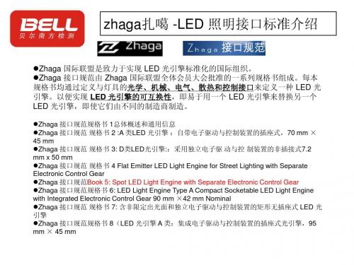
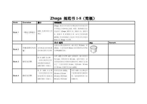
Zhaga规范书1-8(简概)Book Overwiew 接口特殊规范Book 1 一般定义和接口LED 光源的接口的规定Zhaga 规范中涉及的许多测试程序和其他内容并不特定于某种特定光源。
例如,散热测试方法也适用于Zhaga 规格书2、规格书3、规格书4、规格书 5 和规格书6。
而电子控制装置(ECG) 外壳的机械尺寸适用于所有具有分离式ECG 的Zhaga 光引擎。
尺寸+适用样品RemarkBook 2 可插式筒灯光引擎采用集成式控制装置的可插式筒灯光引擎这款光引擎呈园鼓形状,最大直径70.2mm,高45mm。
它采用标准59mm直径的圆形发光界面及PHJ65d基座。
Book 3 射灯光引擎D 类LED 光引擎(采用分离式电子控制装置的非插接式LED 模组)的接口。
该类LED 光引擎LLE 呈圆盘状,最大高度为7.2 mm,典型直径为50 mm,适用于射灯,以及其他需使用小型圆形光源的应用。
规格书 3 指定了一个直径范围为9 mm、13.5 mm、19 mm和23 mm 的圆形发光面(LES)。
Book 4 路灯光引擎D 类LED 光引擎(采用分离式电子控制装置的非插接式LED 模组)的接口。
矩形发光面(LES):30 mm x 7.5 mm42 mm x 10.5 mm60 mm x 15.0 mm该类LED 光引擎适用于需要高强度光源的应用,如街道照明和工业高棚应用Book 5 可插式LED光引擎B 类LED 光引擎(采用分离式电子控制装置的可插式LED 模块)的接口Book 6 紧凑式可插式LED光引擎A 类(采用集成式控制装置的可插式)LED 光引擎的接口Book 7 室内照明光引擎D 类LED 光引擎(采用分离式电子控制装置的非插接式LED 模块)的接口1. L6W6 - 最大长度60mm x 高度60 mm2. L28W2 - 280 x 24 mm3. L28W4 - 281 x 41 mm4. L28W6 - 281 x 61 mm5. L56W4 - 561 x 41 mm包括一系列用于室内照明应用的LED 模块。
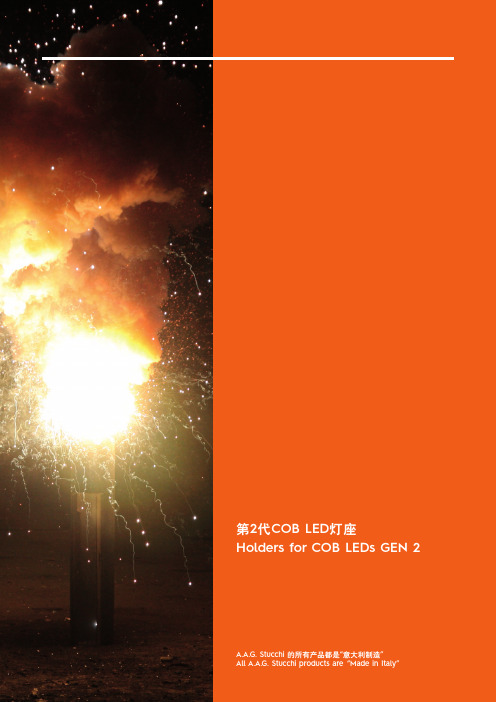
第2代COB LEDHolders for COB LEDs GEN 2 A.A.G. Stucchi 的所有产品都是All A.A.G. Stucchi products are “Made in Italy”www.aagstucchi.it警告- 此产品目前无法在德国销售- 必须遵守LED 生产商提供的规格。
- 必须遵守COB LED 的极性。
- 建议在LED 和散热片之间使用TIM(热接口材料)。
为了实现恰当的热量管理和散热,必须遵守LED生产商的说明书上的要求。
- 强烈建议一次性使用8000/G2系列灯座。
重复使用灯座可能会导致推入式端子和COB固定系统不能用。
- 根据EN/IEC 60838标准的定义,8000/G2系列灯座必须被认为是“敞开式的”:COB LED 正确安装进灯具才能保证防电击。
- 使用M3螺丝(最小长度7mm ,最大扭矩0,5Nm )。
- 必须使用自锁螺丝或锁紧垫圈。
带额外金属板的 “CM” 版本“CM” 版本的灯座配多配了一块金属板,用于重载应用(如存在震动的情况、温度变化很大的室外应用等)。
金属板进一步保证了COB+灯座系统的稳定性和强度,使灯座可靠性最大化。
WARNINGS- Products are not available for the german market - Specifications of LED manufacturer must be observed.- Polarity of COB LED must be observed.- Use of a TIM (Thermal Interface Material) between the LED and the heat sink is recommended. For proper heat management and dissipation, instructions of LED manufacturer must be observed.- Single use of 8000/G2 series holders is strongly recommended. Push-wire terminals and COB holding system failure could be faced trying to re-use an holder.- Holders 8000/G2 series must be considered as “unenclosed”according to the definition stated in the EN/IEC 60838standards: protection against electric shock is guaranteed when the COB LED is properly installed into the lighting fixture.- Use M3 screws (min. length: 7mm - max. torque: 0,5Nm).- Self-locking screws or locking washers must be always used.VERSIONS “CM” WITH ADDITIONAL METAL PLATEHolders “CM” versions are equipped with additional metal plates for use in heavy-duty applications (i.e. in presence of vibrations, in outdoor use with heavy temperature cycles).The metal plates assure a further stability and rigidity to theCOB+holder system maximizing the holder reliability.1)将COB向塑料框一侧按。
L E D常见灯具(灯头)接口介绍----详尽版1 范围本标准规定了电光源用灯头、灯座的命名方法。
2 符号系统本符号系统的目的之一是应使每一个被指定的符号简短、易读并有助于表明其用途。
该符号系统由字母、数字和记号这几个部分组成,每一部分各有自己的含义。
对每一特定的灯头和灯座只应该用一个符号来命名,该符号系统不能用于识别灯头灯座所用材料。
某一符号系统的各部分应直接连在一起,不得有空隙或其它分隔符号。
灯头灯座的完整符号采用下述形式。
灯头符号:(a)(b) (c) - (d) /(e) ×(f)灯座符号:(a) (b) (c) - (d)注:可以采用缩写的灯头符号,但是这种缩写符号不得引起误解。
灯头符号中斜线前面的符号表示对带有某一灯头的在响应灯座中的互换性来说十分重要的内容。
符号中的该特定部分对于灯头及其所用的灯座来说是一样的。
灯头符号中斜线之后的部分(如果存在这部分)表示灯头的某些重要尺寸,但这些尺寸并不是灯在灯座中的互换要求的必须的一部分。
然而,这种尺寸对于装在同型号的灯上的不同来源的灯头的共同互换性来说是十分重要的。
注:IEC的术语与北美术语相反,将无灯头灯的触点部分和固定部分叫做"灯端"。
3 基本符号符号的(a)部分由一个或一个以上的大写字母组成,表示灯头的类型。
下述各字母虽然表示灯头,但是,对于灯座,它们也有类似的意义。
B--卡口灯头;BA--卡口灯头,最初用于汽车灯;BM--矿灯用卡口灯头;E--(爱迪生)螺口灯头;F--带一个出触点的灯头;字母F后的小写字母表示触点的不同形式,例如:a--表示圆柱形插脚;b--表示带凹槽的插脚;c--表示特殊形状的插脚;G--两个或两个以上的凸出触点,例如插脚或接线柱;K--带导线连接件的灯头;P--预聚焦式灯头;R--带凹式触点的灯头;S--外壳式灯头--在灯座中不靠凸出部件来固定灯头;SV--带锥形末端的外壳式灯头(V形);T--电话机用灯头;W---表示灯端,灯与灯座的电接触直接通过位于灯端表面的引线来完成,灯端的玻璃部分(或其它绝缘材料部分)对灯在灯座中的安装来说是必不可少的。
led灯具功率偏差标准
关于LED灯具功率偏差的标准,可以参考国家相关的行业标
准或规范。
以下是一些可能适用的标准:
1. GB/T 24823-2009《电气照明产品的光功率特性测量方法》:该标准规定了电气照明产品(包括LED灯具)的光功率特性
测量方法,其中可能包括功率偏差的测量与要求。
2. GB/T 7000.202-2014《灯具第2部分:LED模块》:该标准
规定了LED模块的技术要求和测试方法,其中可能包括功率
偏差的要求。
3. ISO 9001:2015质量管理体系标准:虽然这是一个质量管
理体系标准,但它也可以用作制定产品功率偏差标准的参考。
该标准注重组织对产品质量的控制,其中包括对产品规格和要求的定义。
4. 行业协会的标准和指南:LED照明行业的一些协会或组织
可能会发布与产品功率偏差相关的标准和指南,如国际照明委员会(CIE)、电气与电子工程师学会(IEEE)等。
需要注意的是,标准的具体内容会根据不同国家或地区可能会有所差异,建议参考本地的行业标准和规范。

灯座规格标准常识:E27、E40、E14 (摘自他人)从安装方式分为卡口、螺口等方式,从材料分为电木、塑料、金属、陶瓷等材料,通常用的灯座如E27是最普遍的节能灯螺口灯座,而配合日光灯的灯座通常称为T8灯座或T5灯座等等,另根据使用环境有的灯座防护级高达IP68,在选购时请根据需要制定相应的IP防护级灯座(防水等),通常用灯座会用到IEC(国际电工委员会标准)安全认证,灯座分类:E14、E27、E12、E26等E开头通常为:螺口灯座GU10等GU开头的指的为我们日常用的卡口式,GU:G表示灯头类型是插入式,U表示灯头部分呈现U字形,后面数字表示灯脚孔中心距(单位是毫米“MM”)。
MR16、MR11以MR开头的是直插式局部照明的小射灯常用这种灯座,通常小射灯有两个插针安装方便。
MR16, GU10是大家的灯座不同,PAR30,38 是直径不同,都是世界通一的标准和叫法,都是灯杯,射灯的叫法,各适合不同的天花灯的灯座。
MR16 在照明行业里指最大外径为2英寸的带多面反射罩的灯具, MP11就是比MR16小一点的灯具,。
MRMR:Multiface Reflect,多面反射(灯杯),后面数字表示灯杯口径(单位是1/8英寸),MR16的口径=16×1/8=2英寸≈50mmPAR灯一般有PAR30 PAR36 PAR46 PAR56,体积有长有短,也叫筒灯,照射光束,用来照明舞台、动感换色等,是舞台上常见的灯具,因为耗电比较大,而且有烤的感觉,现在逐渐被LED PAR灯取代AR111/AR70是铝质冷反光卤素射灯E27、E14是指的普通螺口灯头的灯头大小,E27就是我们平时用的白炽灯的灯头,E14就是比它小一号的,比E27大的还有E40。
G12是一种单端的管形金属卤化物灯泡。
论坛上摘录:MR16是指灯杯的直径, 为50mm. 一般默认的MR16就是的底座,细细的插入式的两个针脚. GU10是指的 twisted 悬扭式的那种底座.目前MR16不管是GU10,还是的底座,都可以作成高压和低压的. 因为这跟灯里面的驱动有关系. 主流是 GU10作高压; 作低压. 但也有不少客户要作成高压的.高压的灯就是直接接入 110~220的市电, 低压的灯就是要中间接着一个高压转低压的变压器(也叫电源).高低压跟灯座没关系. 你总不能拿个的灯接到E27的灯座上吧,严重不匹配.LED封装技术介绍1、扩晶,把排列的密密麻麻的晶片弄开一点便于固晶。

UL由于LED光源与传统电光源有着很大的不同,且现行的UL照明安规标准对于LED光源并无明确的规范,因此早在2005年,UL即着手草拟LED光源产品的安全规范——UL Subject 8750《照明产品中使用的LED 光源的调研框架》,以补充传统照明产品安规标准在LED照明适用上的不足,并计划未来正式生效成为UL 8750安规标准,作为所有以LED为光源的灯具类产品安全检测的主要依据。
现行的UL Subject 8750为2008年7月22日发布的第3版。
对于出口北美地区的LED企业而言,UL Subject 8750将成为其需要遵循的主要安全规范。
UL Subject 8750(3版)内容共分12章,其中第1至4章为适用范围、通用要求、定义等;第5至9章为环境考量、机械结构、电气结构、LED电源、LED 阵列/模块和控制模块;第10至11章为性能测试、异常条件测试;第12章为产品标识。
本节将对其中的主要内容进行介绍。
1. 适用范围UL Subject 8750对照明器具中使用的发光二极管(LED)光源确立了最低安全要求。
其中的LED光源包含下列零组件:将电能转化成光(400至700 nm)或UV辐射(180至400 nm)或红外辐射(700至3000 nm)及热能的LED封装、阵列或模块;提供适当的电压与电流使LED运作的电源;可以进行开关、调光或相反控制LED电能的控制电路。
UL Subject 8750所适用的照明器具一般在依照美国国家电工法规(ANSI/NFPA 70)所列的非危险的环境下使用,并适用于600V及其以下的电源分支。
此外,该规范也适用于与诸如电池、燃料电池等类似的隔离式电源连接的LED光源。
UL Subject 8750所适用的照明器具包括如下几类:灯具,UL 1598;便携式电子灯具,UL 153;舞台与工作室照明,UL 1573;潜水用照明,UL 676;游泳池照明,UL 676;轨道照明系统,UL 157;信号灯,UL 48;紧急照明灯与出口标示灯,UL 924;自镇流灯,UL 1993;逃生出口路径标示系统照明,UL 1994;小夜灯,UL 1786;柔性照明产品,UL 2388;低压照明系统,UL 2108;灯座配件,UL 496;低压景观照明,UL 1838;用于危险场所的灯具,UL 844。
LED模块连结器的安全要求IEC 60838-2-2《杂类灯座-第2-2 部分:LED模块连结器的特别要求》是IEC 于 2006 年公布的一个有关LED模块间连结器的安全规范,它对LED模块连结器的分类、标志、防触电保护、接线端子、接地装置、构造、防潮、绝缘电阻和介电强度、机械强度、螺钉、载流零件和连结件、爬电距离和电气空隙、耐久性、耐热与防火、抗节余应力和抗腐化性、抗震动性能等方面进行了详尽规定。
IEC 60838-2-2中大批引用了 IEC 60838-1《杂类灯座-第 1 部分:通用要乞降测试》中的有关规定,因此应当将这两个标准联合进行考量。
以下对部分要求进行详尽介绍:(1)标准的额定值IEC 60838-2-2规定了所合用的LED模块连结器的最大额定电压为 50 V,最小额定电流为 10 mA,最大额定电流为 3 A,额定工作温度范围为: -30 ℃~ +65 ℃。
(2)防触电保护这部分引用了IEC 60838-1《杂类灯座-第 1 部分:通用要乞降测试》中第7 条的规定,即要求:嵌入式灯座的构造应能使灯座按正常使用安装或嵌装及接线时,其带电零件不该被人涉及;双端灯灯座按正常使用安装接线后,其构造应能使灯座的带电零件不被涉及。
(3)接地装置这部分引用了IEC 60838-1中第 9 条的规定,即要求:除带连结引线的灯座外,带接地装置的灯座应起码有一个接地端子;在灯座上,发生绝缘由障时可能带电的、可涉及金属零件应能靠谱接地;接地端子应坚固锁定,防备不测松动;接线端子所用金属在与接地铜线接触时不该有发生锈蚀的危险;导线固定架的金属部件应与接地电路没关。
(4)构造除了知足 IEC 60838-1 中第 10 条的通用要求外,还规定连结导线的最小横截面积为0.22mm2,如使用带状电缆,则其最小横截面积为 0.09 mm2。
(5)持久性当温度迅速变化或在高湿度环境下,LED 模块用连结器应能与模块保持优秀的电气接触。

LED射灯接口规格有待全面实现统一标准化
随着当代社会日渐进步发展,特别是在照明行业上,自从引进LED技术之后,整个照明行业都发生了翻天覆地的变化。
然而,许多LED灯饰却在规格借口上未能统一的标准。
以LED射灯为例子吧,众多规格接口有待实现标准化。
目前的所有LED射灯都是以替代传统卤钨灯射灯为主,受其外形、灯头和安装要求的限制,使得LED射灯的设计面临许多的困难。
在现有射灯标准的尺寸范围内,很难将LED射灯做到高功率和高光通量,同时配光、散热、电气安全等方面也面临诸多困难,不能体现LED的长寿命、高光效等特点,不利于LED照明的健康发展。
LED本是一种新型光源,LED射灯是最早能体现LED特点的应用产品之一。
应根据LED的特点,制定一套新型的LED射灯规格接口标准。
对LED射灯的外形尺寸、模组分块、参数分档、标准接口等进行规定,实现LED的模块化和互换性,从而推进LED照明的健康发展。
因此,种种情况显示:LED射灯规格接口有待实现标准化。
ZhagaBook18如何帮助路灯接入物联网系统【导读】:日前,Zhaga联盟最近的技术白皮书翻译出炉,书中Zhaga Book 18 是主角,Zhaga Book 18的诞生将解决路灯接入物联网系统遇到的问题。
Zhaga联盟和ZigBee、蓝牙这些联盟有什么不一样呢?Zhaga Book 18技术是如何帮助路灯接入物联网系统的呢?下面这篇文章将带来详细解读。
1. 从一个简单的例子说起在讲ZhagaBook 18之前,我们先讨论一个简单的例子。
这个例子的思路简单、有效,和Zhaga的思路一脉相承。
假设你是一个电子工程师,需要为一个系统快速实现一个主控板。
控制的功能需求是清晰明确的,你做出的板子将交给软件工程师开发软件。
这是每个公司每天都在发生的事。
首先,你想到的是功能需求分析和电路实现。
前面说了,这个系统定义清晰明确,你可以很快拿出一个方案来。
问题是,软件会有什么需求?选择什么样的处理器更合适?考虑到可能的需求变化,在处理器的选择上你有太多选项:1)成本优先,尽可能简单。
你可以选择单片机(MCU)。
下一步,什么型号?2)性能优先,为将来软件升级提供余量。
你可以选择嵌入式处理器(SoC)。
下一步,选哪个公司?什么型号?3)软硬件协同设计,提供最大程度的可编程性。
你可以选择FPGA。
同样地,Xilinx,Altera,Actel,选哪家?什么型号?这个问题可以表示成图1:图1.电子工程师遇到的问题如何解决?一个简单而有效地思路是:将不确定的部分从确定的部分中抽离出去,使得固定的部分可以快速地实现而灵活的部分可以简便地接入主控板。
在这个例子中,我们只要将处理器的外部接口定义清楚(因为系统的功能清楚,所以这个不难做到),即可通过几个标准的排针将CPU部分拆解出来。
如图2所示。