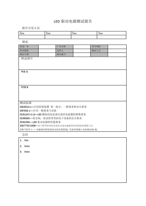
东三积体电子LED test report_Osram
- 格式:pdf
- 大小:274.41 KB
- 文档页数:5
硬件模块单元测试报告编制: 日期:审核: 日期: 批准: 日期:目录目录 (1)第一章概述 (3)1.1目的和范围 (3)1.2测试概述 (3)第二章测试资源及环境 (4)2.1 硬件配置 (4)2.2 测试设备清单 (4)2.3 测试环境 (4)2.4 测试方式 (4)第三章测试数据 (6)3.1 主控板测试 (6)3.1.1短路测试 (6)3.1.2直流电压、纹波测试 (6)3.1.3接口通讯信号测试 (8)3.1.3.1主控板与按键板打印部分 (8)3.1.3.2主控板与核心板 (8)3.1.3.3主控板与液晶屏 (8)3.1.3.4主控板与触摸屏 (9)3.1.3.5主控板与感光板 (10)3.1.3.6主控板对按键板指示灯部分检测信号 (10)3.1.3.8主控板与WIFI板 (10)3.1.4充电测试 (11)3.1.5电源转换效率测试 (11)3.1.5.1 5V电源转换效率测试 (11)2.1.5.2 +8V电源转换效率测试 (13)3.1.6 DC_DC带负载测试 (14)3.2 按键板测试 (15)3.2.1短路测试 (15)3.2.2直流电压、纹波测试 (15)3.2.3接口通讯信号测试 (15)3.2.3.1 按键板与打印机 (15)第一章概述1.1目的和范围本文描述H3硬件模块的测试方法和步骤, 本方案的来源是《H3硬件总体需求》和《H3硬件总体方案》适用范围是:1.2测试概述在硬件模块测试阶段, 测试人员根据细化后的方案进行集成测试, 测试的重点是接口, 主要包括以下几个方面:1.各个板卡接口和测试点电压纹波测试2.控制/检测信号逻辑状态分析第二章测试资源及环境2.1 硬件配置2.3 测试环境环境温度: 0-55℃;大气压力: 700hPa~1060hPa;相对湿度:15% ~ 95%, 非凝2.4 测试方式内部测试第三章测试数据3.1 主控板测试3.1.1短路测试3.1.3接口通讯信号测试3.1.3.1主控板与按键板打印部分3.1.3.2主控板与核心板3.1.3.3主控板与液晶屏3.1.3.4主控板与触摸屏3.1.3.5主控板与感光板3.1.3.8主控板与WIFI板3.1.4充电测试使用电源交流100~240Vac 50Hz/60Hz 使用内置锂电池 12.6V/2600mA3.1.6 DC_DC带负载测试3.2 按键板测试3.2.1短路测试3.2.3接口通讯信号测试3.2.3.1 按键板与打印机。
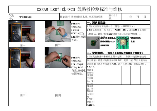
发行号:性能说明发行日期:图一 2.2白光检测条件和标准见图三与图四,如图三电源DC输出端并图三接万用表,调整好电压至标准2.35V,见图二按LED正负极方向通电检测(芯片发出微光为OK;芯片不亮为NG,作好标识)。
2.2蓝光检测条件和标准见图三与图四,如图五电源DC输出端并接万用表,调整好电压至标准2.23V,见图二按LED正负极方向通电检测(芯片发出微光为OK;芯片不亮为NG,作好标识)。
图五承认:确认一:确认二:作成:陈世海PCB板号:226D105,LUW CCQDP-KULQ-5C8E-1白光LED通电检测方法。
图六图四PCB板号:226D105,LBCPDP-GYHY-35蓝光LED通电检测方法。
三、维修:见附页OSRAM LED灯珠+PCB 线路板维修图二与PCB方向二、检测流程:(操作人员必须配带防静电手圈作业)2.1红光检测条件和标准见图一与图二,如图一电源DC输出端接万用表,调整好电压至标准1.50V,见图二按LED正负极方向通电检测(芯片发出微光为OK;芯片不亮为NG,作好标识)。
OSRAM LED灯珠+PCB 线路板检测标准与维修JT-226D105用恒流恒压电源,恒压限流检测 年 月 日PCB板号:226D105,LRCPDP-HZKX-1红光LED通电检测方法。
一、测试前准备:1.1恒流恒压可调电源一台(型号:APS3005S1)。
1.2数显万能表一台(型号:FLUKE 15B),测出LED正负极性(经测试,此红/蓝/白LED封装有缺口方向均为负极)。
此为通电测试点, 缺口方向为 贴装时需统一LED 负极附:OSRAM LED灯珠+PCB 线路板维修方法一、以上检测如有NG,按以下步骤检查与维修:a、LED有无贴装反向。
(确认方法:反向接通测试点可判断)b、焊点有无连锡(短路)或虚焊(开路)。
(确认方法:通电测试后,测试会听见电源短路声或光源不亮)c、PCB线路走线有无制造不良断路、短路。
APPLICATION FOR LOW VOLTAGE DIRECTIVEOn Behalf ofShenzhen Xuxing Telecom Technology Co.,Ltd.Li-ion BatteryModel: A1, X8Prepared For : Shenzhen Xuxing Telecom Technology Co.,Ltd.14I,Block A, Huaqiang Plaza, No.1019Huaqiang North Road, Futian District,Shenzhen,ChinaPrepared By : Most Technology Service Co., Ltd.No. 5, 2nd Langshan Road, North District, Hi-techIndustrial Park, Nanshan, Shenzhen,Guangdong, ChinaTEL : 0755 – 86170306FAX : 0755 – 86170310Date of receipt of test item : January 13, 2011Report Reference Number : SZSTS110103EU______ST/SG/AC.10/11Rev.5 Section 38.3Clause Requirement- Test Result - Remark Verdict38.3 Lithium metal and lithium ion batteries P 38.3.1 Purpose PThis section presents the procedures to be followedfor the classification of Lithium metal and lithium ioncells and batteries.P 38.3.2 Scope P 38.3.2.1 Lithium metal and lithium ion cells and batteries whichdiffer from a tested type by:Pa) For primary cells and batteries, a change of morethan 0.1 g or 20% by mass, whichever is greater, tothe cathode, to the anode, or to the electrolyte.Nb) For rechargeable cells and batteries, a change inwatt-hours of more than 20% or an increase in voltageof more than 20%.Pc) A change that would materially affect the testresults. Shall be considered a new type and shall besubjected to the required test.P38.3.2.2 I For the purposes of classification, the followingdefinitions apply:P38.3.3 When a cell or battery type is to be tested underthis sub-section, the number and condition ofcells and batteries of each type to be tested are asfollows: Tests 1 to 5 must beconducted in sequence onthe same battery,Pa) When testing primary cells and batteries undertests 1 to 5, the following shall be tested:N Ten cells in undischarged states, N Ten cells in fully discharged states, N Four small batteries in undischarged states, N Four small batteries in fully discharged states, N Four large batteries in undischarged states N Four large batteries in fully discharged states N b) when testing rechargeable cells and batteries undertests 1 to 5 the following shall be tested:P Ten cells at first cycle, in fully charged states, N Four small batteries at first cycle, in fully chargedstates.P Four small batteries 50 cycle ending in fully chargedstates.P Two large batteries at first cycle, in fully chargedstates. N Two large batteries 25 cycle ending in fully chargedstates.NClause Requirement- TestResult - RemarkVerdict______c) When testing primary and rechargeable cells under test 6(Impact), the following shall be tested in the quantity indicated:PFor primary cells, five cells in undischarged states and five cells in fully discharged statesPFor component cells of primary batteries, Five cells in undischarged states and five cells in fully discharged states.NFor rechargeable cells, five cells at first cycle at 50% of the design rated capacity,N For components cells of rechargeable batteries, five cells at first cycle at 50% of the design rated capacity.PFor prismatic cells, ten test cells are required instead of the five described above, so that the procedure can be carried out on five cells along the longitudinal axes and, separately, five cells along the other axes. In every case, the test cell is only subjected to one impacPd) When testing rechargeable batteries under test 7(Overcharge), the following shall be tested in the quantity indicated:PFour small batteries at first cycle, in fully charged states.P Four small batteries after 50 cycles ending in fully charged states.P Two large batteries at first cycle, in fully charged states,N Two large batteries after 25 cycles ending in fully charged states.Ne) When testing primary and rechargeable cells under test 8(Forced Discharge), the following shall be tested in the quantity indicated:The requirement is not applicable to test batteries. N Ten primary cells in fully discharged states N Ten rechargeable cells, at first cycle in fully discharged statesN Ten rechargeable cells after 50 cycles ending in fullydischarged statesNf) when testing a battery assembly in which the aggregate lithium content of all anodes, when fully charged, is not more than 500g, or in the case of a lithium ion battery, with a watt-hour rating of not more than 6200 Watt-hoursNClause Requirement- Test Result - Remark Verdict______38.3.4 ProcedurePTest 1 to 5 must be conducted in sequence on the same cell or battery.P Test 6 and 8 should be conducted using not otherwisetested cells or batteriesPTest 7 may be conducted using undamaged batteriespreviously used in tests 1 to 5 for purposes of testing on cycled batteriesP38.3.4.1 Test 1: Altitude Simulation P 38.3.4.1.1 Purpose P This test simulates air transport under low-pressureconditions.-- 38.3.4.1.2 Test procedureP stored at a pressure 11.6 kPa -- ambient temperature (20 ± 5).℃ 24℃ -- Stored times( ≥ 6 hours) 8 hours. -- 38.3.4.1.3 RequirementCells and batteries meet this requirement if there is nomass loss, no leakage, no venting, no disassembly, no rupture and no fire and if the open circuit voltage of each test cell or battery after testing is not less than 90% of its voltage immediately prior to this procedure. The requirement relating to voltage is not applicable to test cells and batteries at fully discharged statesNo mass loss, no leakage, no venting, no disassembly, no rupture and no fire. Battery after testing is not less than 90% of its voltageimmediately prior to this procedure.PMass M of Test Battery (g)OCV (V) Group No.M1 (beforet he test) M2 (after the test)MassLoss limit(0.1%)OCV1 (beforethe test) OCV2 (after the test) OCV (≥90%)01 21.223g 21.223g0.00%3.861 3.861 100.0% 02 21.178g 21.178g 0.00%3.867 3.867 100.0%03 21.338g 21.338g 0.00%3.866 3.866 100.0% Group A (at first cycle, infully charged states) 04 21.385g 21.385g 0.00% 3.862 3.862 100.0% 05 21.142g 21.142g 0.00%3.865 3.865 100.0% 06 21.465g 21.465g 0.00%3.854 3.854 100.0% 07 21.276g 21.276g 0.00%3.860 3.860 100.0% Group B (after fiftycycles ending in fullycharged states)08 21.328g 21.328g 0.00%3.8673.867100.0%Remark1.Mass loss (%)=(M1-M2)/M1*100% (Where M 1 is the mass before the test and M 2 is the mass after the test)2.When mass loss does not exceed the value in Table: Mass loss limit, it shall be considered as "no mass loss".3.The OCV of each test cell after testing is not less than 90% of its voltage immediately prior to this procedure.4. Ambient temperature: 24℃Conclusion:Clause Requirement- TestResult - RemarkVerdict______Li-ion Battery had passed altitude simulation test.38.3.4.2 Test 2: Thermal Test P 38.3.4.2.1 Purpose P This test assesses cell and battery seal integrity andinternal electrical connections. The test is conducted using rapid and extreme temperature changes.P38.3.4.2.2 Test procedurePTest temperature and stored hours 1) 75℃, ≥6h 2) -40℃, ≥6h-- The maximum time intervalBetween test temperature extremes is 30 minutes. --Test timesrepeated 10 times -- After which all test cells and batteries are to be storedfor 24 hours at ambient temperature (20±5℃)24℃ -- For large cells and batteries the duration of exposure tothe test temperature extremes should be at least 12 hours.Small batteryN 38.3.4.2.3 RequirementCells and batteries meet this requirement if there is nomass loss, no leakage, no venting, no disassembly, no rupture and no fire and if the open circuit voltage of each test cell or battery after testing is not less than 90% of its voltage immediately prior to this procedure. The requirement relating to voltage is not applicable to test cells and batteries at fully discharged statesNo mass loss, no leakage, no venting, no disassembly, no rupture and no fire. Battery after testing is not less than 90% of its voltageimmediately prior to this procedure.PMass M of Test Battery (g)OCV (V) Group No. M1 (beforet he test) M2(afterthe test)MassLosslimit(0.1%)OCV1 (beforethe test) OCV2 (after the test) OCV (≥90%) 01 21.223g 21.223g 0.00%3.861 3.835 99.33%02 21.178g 21.178g 0.00%3.867 3.854 99.66% 03 21.338g 21.338g 0.00% 3.866 3.845 99.46% Group A (at first cycle, in fully charged states)04 21.385g 21.385g 0.00% 3.862 3.836 99.33% 05 21.142g 21.142g 0.00%3.865 3.842 99.40% 06 21.465g 21.465g 0.00%3.854 3.836 99.53% 07 21.276g 21.276g 0.00%3.860 3.837 99.40% Group B (after fiftycycles ending in fullycharged states)08 21.328g 21.328g 0.00%3.8673.85399.64%Remark1.Mass loss (%)=(M1-M2)/M1*100% (Where M 1 is the mass before the test and M 2 is the mass after the test)2.When mass loss does not exceed the value in Table: Mass loss limit, it shall be considered as "no mass loss".3.The OCV of each test cell after testing is not less than 90% of its voltage immediately prior to this procedure.4. Ambient temperature: 24℃Conclusion:Clause Requirement- TestResult - RemarkVerdict______Li-ion Battery had passed thermal test.38.3.4.3 Test 3: Vibration P 38.3.4.3.1 PurposePThis test simulates vibration during transport..P 38.3.4.3.2 Test procedure PCells and batteries are firmly secured to the platform of the vibration machine without distorting the cells insuch a manner as to faithfully transmit the vibration.-- The vibration shall be a sinusoidal waveform with a logarithmicP Duration 15min -- Frequency range 7Hz... ..200Hz.....7Hz -- Amplitude 0.8mm -- This cycle shall be repeated 12 times for a total of 3 hours for each of three mutually perpendicular mounting positions of the cell.-- 38.3.4.3.3 Requirement PCells and batteries meet this requirement if there is no mass loss, no leakage, no venting, no disassembly, no rupture and no fire and if the open circuit voltage of each test cell or battery after testing is not less than 90% of its voltage immediately prior to this procedure. The requirement relating to voltage is not applicable to test cells and batteries at fully discharged states No mass loss, no leakage,no venting, no disassembly, no rupture and no fire. PMass M of Test Battery (g) OCV (V)GroupNo. M1 (beforet he test) M2(afterthe test)MassLosslimit(0.1%)OCV1 (beforethe test) OCV2 (after the test) OCV (≥90%) 01 21.223g 21.223g 0.00% 3.835 3.835 100.0% 02 21.178g 21.178g 0.00% 3.854 3.854 100.0% 03 21.338g 21.338g 0.00% 3.845 3.845 100.0% Group A (at first cycle, in fully charged states) 04 21.385g 21.385g 0.00% 3.836 3.836 100.0% 05 21.142g 21.142g 0.00% 3.842 3.842 100.0% 06 21.465g 21.465g 0.00% 3.836 3.836 100.0% 07 21.276g 21.276g 0.00% 3.837 3.837 100.0% Group B (after fifty cycles ending in fully charged states)08 21.328g 21.328g 0.00%3.8533.853100.0%Remark1.Mass loss (%)=(M1-M2)/M1*100% (Where M 1 is the mass before the test and M 2 is the mass after the test)2.When mass loss does not exceed the value in Table: Mass loss limit, it shall be considered as "no mass loss".3.The OCV of each test cell after testing is not less than 90% of its voltage immediately prior to this procedure.4. Ambient temperature: 24℃Conclusion:Li-ion Battery had passed vibration test.Clause Requirement- TestResult - RemarkVerdict______38.3.4.4 Test 4: Shock P 38.3.4.4.1 PurposePThis test simulates vibration during transport..P 38.3.4.4.2 Test procedurePTest cells and batteries shall be secured to the testing machine by means of a rigid mount which will support all mounting surfaces of each test battery.This is small batteries. -- a half-sine shock of peak acceleration 150 g P Pulse duration 6ms -- the positive direction followed three times shocks --Each cell or battery shall be subjected to three shocks in the positive direction followed by three shocks in the negative direction of three mutually perpendicular mounting positions of the cell or battery for a total of18 shocks.--38.3.4.4.3 Requirement PCells and batteries meet this requirement if there is no mass loss, no leakage, no venting, no disassembly, no rupture and no fire and if the open circuit voltage of each test cell or battery after testing is not less than 90% of its voltage immediately prior to this procedure. The requirement relating to voltage is not applicable to test cells and batteries at fully discharged states No mass loss, no leakage,no venting, no disassembly, no rupture and no fire. PMass M of Test Battery (g) OCV (V)GroupNo. M1 (beforet he test) M2(afterthe test)MassLosslimit(0.1%)OCV1 (beforethe test) OCV2 (after the test) OCV (≥90%) 01 21.223g 21.223g 0.00% 3.835 3.835 100.0% 02 21.178g 21.178g 0.00% 3.854 3.854 100.0% 03 21.338g 21.338g 0.00% 3.845 3.845 100.0% Group A (at first cycle, in fully charged states) 04 21.385g 21.385g 0.00% 3.836 3.836 100.0% 05 21.142g 21.142g 0.00% 3.842 3.842 100.0% 06 21.465g 21.465g 0.00% 3.836 3.836 100.0% 07 21.276g 21.276g 0.00% 3.837 3.837 100.0% Group B (after fifty cycles ending in fully charged states)08 21.328g 21.328g 0.00%3.8533.853100.0%Remark1.Mass loss (%)=(M1-M2)/M1*100% (Where M 1 is the mass before the test and M 2 is the mass after the test)2.When mass loss does not exceed the value in Table: Mass loss limit, it shall be considered as "no mass loss".3.The OCV of each test cell after testing is not less than 90% of its voltage immediately prior to this procedure.4. Ambient temperature: 24℃Conclusion:Li-ion Battery had passed shock test.Clause Requirement- TestResult - RemarkVerdict______38.3.4.5 Test 5: External Short Circuit P 38.3.4.5.1 PurposePThis test simulates an external short circuit. P 38.3.4.5.2 Test procedurePThe cell or battery to be tested shall be temperature stabilized so that its external case temperature reaches 55℃--Short circuit condition with a total External resistance of less than 0.1ohm--The cell or battery must be observed for a further six hours for the test to be concluded.--This short circuit condition is continued for at least one hour after the cell or battery external case temperature has returned to 55℃-- 38.3.4.5.3 RequirementPCells and batteries meet this requirement if theirexternal temperature does not exceed 170℃ and there is no disassembly, no rupture and no fire within six hours of this test. Battery externaltemperature does notexceed 170℃, and there is no disassembly, no fire and no rupture within six hours of this testPGroupNo.External Highest Temperature(℃)Criteria Result0155.6℃ P 02 55.5℃ P 03 55.7℃ P Group A (at first cycle, in fully charged states)04 55.9℃ P 05 55.6℃ P 06 55.7℃ P 07 55.8℃ P Group B (after fifty cycles ending in fully charged states) 0855.9℃Battery external temperature does not exceed 170℃, and there is no disassembly, no fire and no rupture within six hours of this testPAmbient temperature: 23℃Conclusion:Li-ion Battery had passed external short circuit test.Clause Requirement- TestResult - RemarkVerdict______38.3.4.6 Test 6: ImpactThe test sample Component cell of chargeable batteries. P 38.3.4.6.1 PurposePThis test simulates an impact. P 38.3.4.6.2 Test procedureP - Dropped height 61±2.5cm, -- - mass9.1Kg -- - diameter bar 15.8mm --- Impact position:Prismatic cell is to be impacted with its longitudinal axis parallel to the flat surface and perpendicular to the longitudinal axis of the 15.8 mm diameter curved surface lying across the centre of the test sample, Prismatic cell is also to be rotated 90 degrees around its longitudinal axis so that both the wide and narrow sides will be subjected to the impact.--A coin or button cell is to be impacted with the flat surface of the sample parallel to the flat surface and the 15.8 mm diameter curved surface lying across its centre.38.3.4.6.3 RequirementPCells and batteries meet this requirement if theirexternal temperature does not exceed 170℃ andthere is no disassembly, no rupture and no fire within six hours of this test.Battery external temperature does not exceed 170℃, and there isno disassembly, no fire and no rupture within six hours of this testPGroup No. ExternalHighestTemperature(℃)Criteria Result0178.2℃ P 02 76.3℃ P 03 79.4℃ P 04 80.6℃ P Group A (at first cycle, in fully charged states)05 78.5℃ P 0648.3℃ P 07 47.6℃ P 08 50.3℃ P 09 48.6℃ P Group B (after fifty cycles ending in fullycharged states) 1047.9℃Battery external temperature does not exceed 170℃, and there is no disassembly, no fire and no rupture within six hours of this testPAmbient temperature: 23℃Clause Requirement- TestResult - RemarkVerdict______Conclusion:Li-ion Battery had passed Impact test.38.3.4.7 Test 7: OverchargeP 38.3.4.7.1 PurposePThis test evaluates the ability of a rechargeable battery to withstand an overcharge condition.P 38.3.4.7.2 Test procedurePThe charge current2×900=1800mA, Twice the manufacturer'srecommended maximum continuous charge current--The minimum voltage of the test:--a) The minimum voltage of the test (Themanufacturer ’s recommended charge voltage is not more than 18V).2×4.2=8.4V, the lesser of two times the maximum charge voltage of the battery or 22V,-- Ambient temperature. 24℃ -- The duration of the test.24 hours 38.3.4.7.3 RequirementPRechargeable batteries meet this requirement if there is no disassembly and no fire within seven days of the testThere is no disassemblyand no fire within seven days of the test.PGroupNo. CriteriaResult 01P 02 P 03 P Group A (at first cycle, in fully charged states)04 P 05 P 06 P 07 P Group B (after fifty cycles ending in fully charged states) 08There is no disassembly and no fire within seven days of the test.P Ambient temperature: 24℃Conclusion:Li-ion Battery had passed overcharge test.Clause Requirement- TestResult - RemarkVerdict______38.3.4.8 Test 8: Forced discharge N 38.3.4.8.1 PurposeNThis test evaluates the ability of a primary or a rechargeable cell to withstand a forced discharge condition.-- 38.3.4.8.2 Test procedureNEach cell shall be forced discharged at ambient temperature by connecting it in series with a 12 V DC, power supply at an initial current equal to the maximum discharge current specified by the manufacturer.NThe specified discharge current is to be obtained by connecting a resistive load of the appropriate size and rating in series with the test cell, Each cell shall be forced discharged for a time interval (in hours) equal to its rated capacity divided by the initial test current (in ampere)N38.3.4.8.3 RequirementNPrimary or rechargeable cells meet this requirement if there is no disassembly and no fire within seven days of the test.NPHOTOGRAPHS OF EUT。

LED显示屏基本知识及计算方法一、LED显示屏基础知识2二、LED显示屏的分类4三、怎样选购LED全彩显示屏的规格5四、LED显示屏各项参数的概念7五、控制 LED 亮度的方法:10六、LED屏的各种计算方法:11七、LED显示屏常用安装方式15八、LED显示屏的控制系统16九、LED显示屏大小的计算方式17一、LED显示屏基础知识1.LED及LED显示屏1)什么是LED在某些半导体材料的 PN 结中,注入的少数载流子及多数载流子复合时会把多余的能量以光的形式释放出来,从而把电能直接转换为光能。
PN 结加反向电压,少数载流子难以注入,故不发光。
这种利用注入式电致发光原理制作的二极管叫发光二极管,通称 LED (全拼:light emitting diode)。
LED 的发光颜色和发光效率及制作 LED 的材料和工艺有关,目前广泛使用的有红、绿、蓝(R、G、B)三种。
由于 LED 工作电压低(仅 1.5-3V ),能主动发光且有一定亮度,亮度又能用电压(或电流)调节,本身又耐冲击、抗振动、寿命长(10万小时),所以在大型的显示设备中,目前尚无其他的显示方式及 LED 显示方式匹敌。
把红色和绿色的 LED 放在一起作为一个象素制作的显示屏叫双色屏或彩色屏;把红、绿、蓝三种 LED 管放在一起作为一个象素的显示屏叫三色屏或全彩屏。
制作室内 LED 显示屏的象素尺寸一般是 2-10 毫米,常常采用把几种能产生不同基色的 LED 管芯封装成一体,室外 LED显示屏的象素尺寸多为 12-26 毫米,每个象素由若干个各种单色 LED 组成,常见的成品称象素筒,双色象素筒一般由 3 红 2 绿组成,三色象素筒用 2 红 1 绿 1 兰组成。
无论用 LED 制作单色、双色或三色屏,欲显示图象需要构成象素的每个 LED 的发光亮度都必须能调节,其调节的精细程度就是显示屏的灰度等级。
灰度等级越高,显示的图像就越细腻,色彩也越丰富,相应的显示控制系统也越复杂。
LED检验报告一、报告背景随着互联网的不断发展,智能家居、智能办公等领域的发展越来越快速,而LED(Light Emitting Diode,发光二极管)作为一种高效节能、寿命长的照明产品受到了越来越多的关注和应用。
为了确保LED的质量和可靠性,进行LED产品的检验是非常重要的,本报告旨在对LED进行全面的检验和评估。
二、检验目的1.确定LED的外观质量,包括表面是否有划痕、变形等;2.测试LED的光性能指标,包括亮度、颜色温度、色彩准确度等;3.检查LED的电气性能,包括输入电压范围、电流、功率等;4.对LED的耐久性进行评估,包括长时间工作的性能稳定性。
三、检验方法1.外观质量检验:使用目视检查法,对LED的表面进行仔细观察和比对;2.光性能指标测试:使用光谱仪测量LED的亮度、颜色温度和色彩准确度;3.电气性能测试:使用电压表和电流表分别检测LED的输入电压范围、电流和功率;4.耐久性评估:使用长时间开启LED,并监测其亮度变化。
四、检验结果及分析1.外观质量:经过外观检验,LED表面无明显划痕和变形,符合外观质量要求。
2.光性能指标:使用光谱仪测试了LED的亮度、颜色温度和色彩准确度,测试结果如下:- 亮度:LED的亮度为XXXcd,符合亮度指标要求。
-颜色温度:LED的颜色温度为XXXK,符合颜色温度指标要求。
-色彩准确度:在CIE色度图上的坐标为(XXX,XXX),符合色彩准确度指标要求。
3.电气性能:使用电压表和电流表测量了LED的输入电压范围、电流和功率,测试结果如下:-输入电压范围:LED的输入电压范围为XXXV,符合输入电压范围要求。
-电流:LED的电流为XXXA,符合电流指标要求。
-功率:LED的功率为XXXW,符合功率指标要求。
4.耐久性评估:经过长时间的开启测试,LED的亮度保持稳定,未出现亮度衰减等现象,符合耐久性要求。
五、检验结论根据对LED的外观、光性能、电气性能和耐久性的全面检查和评估,LED产品符合质量要求,具有良好的品质和稳定性能。


光信息专业实验报告:LED 特性及光度测量实验摘要:本实验目的在于了解发光二极管的发光机理、光学特性与电学特性,掌握其测试方法。
通过设计简单的测试装置,并对发光二极管进行V -I 特性曲线、P-I 特性曲线的测量,以此研究探讨LED 发光器件的发光特性,加深对于发光二极管的理解。
关键词:发光二极管,V -I 特性,P -I 特性,光度【实验用具】LED (若干种类)、精密数显直流稳流稳压电源、积分球(Φ=30cm )、多功能光度计、通用标准光源、光功率计、直尺、万用表、导线等。
【实验原理】LED 是英文light emitting diode (发光二极管)的缩写,它属于固态光源,其基本结构是一块电致发光的半导体材料,置于一个有引线的架子上,然后四周用环氧树脂密封,起到保护内部芯线的作用(如图1)。
常规的发光二极管芯片的结构如图2所示,主要分为衬底,外延层(图2中的N型氮化镓,铝镓铟磷有源区和P 型氮化镓),透明接触层,P 型与N 型电极、钝化层几部分。
图2、常规InGaN / 蓝宝石LED 芯片剖面图发光二极管的核心部分是由p 型半导体和n 型半导体组成的晶片,在p 型半导体和n 型半导体之间有一个过渡层,称为p-n 结。
跨过此p -n 结,电子从n 型材料扩散到p)区,而空穴则从p 型材料扩散到n 区,如右面的图3(a)所示。
作为这一相互扩散的结果,在p-n结处形成了一个高度的eΔV的势垒,阻止电子和空穴的进一步扩散,达到平衡状态(见图3(b))。
当外加一足够高的直流电压V,且p 型材料接正极,n型材料接负极时,电子和空穴将克服在p-n结处的势垒,分别流向p 区和n 区。
在p-n结处,电子与空穴相遇,复合,电子由高能级跃迁到低能级,电子将多余的能量将以发射光子的形式释放出来,产生电致发光现象。
这就是发光二极管的发光原理。
选择可以改变半导体的能带隙,从而就可以发出从紫外到红外不同波长的光线,且发光的强弱与注入电流有关。
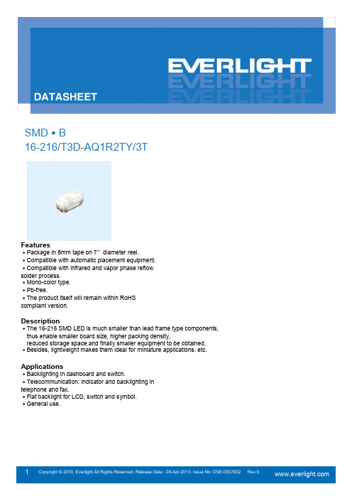
16-216/T3D-AQ1R2TY/3TFeatures․Package in 8mm tape on 7〞diameter reel.․Compatible with automatic placement equipment.․Compatible with infrared and vapor phase reflowsolder process.․Mono-color type.․Pb-free.․The product itself will remain within RoHScompliant version.Description․The 16-216 SMD LED is much smaller than lead frame type components, thus enable smaller board size, higher packing density,reduced storage space and finally smaller equipment to be obtained.․Besides, lightweight makes them ideal for miniature applications. etc. Applications․Backlighting in dashboard and switch.․Telecommunication: indicator and backlighting intelephone and fax.․Flat backlight for LCD, switch and symbol.․General use.InGaN Pure White Yellow DiffusedReverse Voltage V R 5 VForward Current I F25 mAPeak Forward Current(Duty 1/10 @1KHz)I FP100 mAPower Dissipation Pd110 mW Operating Temperature T opr-40 ~ +85 ℃Storage Temperature Tstg -40 ~ +90 ℃Electrostatic Discharge ESD HBM150 VSoldering Temperature T sol Reflow Soldering : 260 ℃for 10 sec. Hand Soldering : 350 ℃for 3 sec.Luminous Intensity Iv 72 ----- 180 mcdI F=5mA Viewing Angle 2θ1/2----- 130 ----- degForward Voltage V F 2.6 ---- 3.0 VReverse Current I R----- ----- 50 μA V R=5VNote:1. Tolerance of Luminous Intensity: ±11%2. Tolerance of Forward Voltage: ±0.05VBin Range of Luminous IntensityQ1 72 90 mcd I F =5mAQ2 90 112 R1 112 140 R2140180Bin Range Of Luminous Voltage28 2.6 2.7 mcd I F =5mA29 2.7 2.8 30 2.8 2.9 312.93.0Note:1. Tolerance of Luminous Intensity: ±11%2. Tolerance of Forward Voltage: ±0.05VA10.274 0.226 I F =5mA0.274 0.258 0.294 0.286 0.294 0.254 20.274 0.258 0.274 0.291 0.294 0.319 0.294 0.286 30.294 0.254 0.294 0.286 0.314 0.315 0.314 0.282 40.294 0.286 0.294 0.319 0.314 0.347 0.314 0.315 50.314 0.282 0.314 0.315 0.334 0.343 0.334 0.311 60.314 0.315 0.314 0.347 0.334 0.376 0.3340.343Notes:1.The C.I.E. 1931 chromaticity diagram ( Tolerance ±0.01 ).2.The products are sensitive to static electricity and care must be fully taken when handling products.Typical Electro-Optical Characteristics CurvesR e l a t i v e l u m i n o u s i n t e n s i t y )(%4002505075100500600700800Spectrum DistributionWavelength λ (nm)Ta=25°CR e l a t i v e l u m i n o u s i n t e n s i t y (%)Forward Current vs.Forward VoltageTa=25°CF o r w a r d C u r r e n t I (m A )F F Forward Voltage V (V)Forward Current Luminous Intensity vs.Ta=25°CR e l a t i v e l u m i n o u s i n t e n s i t y %)( Luminous Intensity vs.Ambient TemperatureForward Current I (mA) F Radiation DiagramTa=25°CForward Current Derating CurveAmbient Temperature Ta (°C)Ambient Temperature Ta (°C)F o r w a r d C u r r e n tI (m A )FPackage DimensionSuggested pad dimension is just for reference only. Please modify the pad dimension based on individual need. Note: Tolerances unless mentioned ±0.1mm. Unit = mmMoisture Resistant Packing MaterialsLabel Explanation‧CPN: Customer ’s Product Number ‧P/N: Product Number ‧QTY: Packing Quantity‧CAT: Luminous Intensity Rank ‧HUE: Chromaticity Coordinates ‧REF: Forward Voltage Rank ‧LOT No: Lot NumberReel DimensionsNote: The tolerances unless mentioned is ±0.1mm ,Unit = mmCarrier Tape Dimensions: Loaded quantity 3000 PCS per reelPrecautions For Use1. Over-current-proofCustomer must apply resistors for protection, otherwise slight voltage shift will cause bigcurrent change ( Burn out will happen ).2. Storage2.1 Do not open moisture proof bag before the products are ready to use.2.2 Before opening the package: The LEDs should be kept at 30℃or less and 90%RH or less.2.3 After opening the package: The LED's floor life is 1 year under 30℃or less and 60% RH or less.If unused LEDs remain, it should be stored in moisture proof packages.2.4 If the moisture absorbent material (silica gel) has faded away or the LEDs have exceeded theBaking treatment : 603.3 When soldering, do not put stress on the LEDs during heating.3.4 After soldering, do not warp the circuit board.4.Soldering IronEach terminal is to go to the tip of soldering iron temperature less than 350℃for 3 seconds within once in less than the soldering iron capacity 25W. Leave two seconds and more intervals, and do soldering of each terminal. Be careful because the damage of the product is often started at the time of the hand solder.5.RepairingRepair should not be done after the LEDs have been soldered. When repairing is unavoidable, a double-head soldering iron should be used (as below figure). It should be confirmed beforehand whether the characteristics of the LEDsApplication RestrictionsHigh reliability applications such as military/aerospace, automotive safety/security systems,and medical equipment may require different product. If you have any concerns, please contact Everlight before using this product in your application. This specification guarantees the quality and performance of the product as an individual component. Do not use this product beyond the specification described in this document.。
欧司朗检测报告和合格证【标题】欧司朗检测报告和合格证:品质保证的关键纽带【引言】当我们购买电子产品时,往往关注的不仅是外观与功能,更重要的是产品的品质。
为了确保产品符合标准,并且能够安全可靠地使用,欧司朗(OSRAM)作为一家领先的光电子公司,注重品质控制,并提供了欧司朗检测报告和合格证。
这两个文档在保障产品品质、树立行业形象以及满足用户需求方面发挥着重要作用。
本文将深入探讨欧司朗检测报告和合格证的背后意义,并分享个人对这些文档的理解和观点。
【内容】1. 欧司朗检测报告的作用与意义1.1 规范产品质量标准检测报告是欧司朗对产品进行全面检测的结果总结,它详细记载了产品的物理性能、安全性和可靠性。
这些数据不仅能够反映产品的质量水平,还为制定和改进产品质量标准提供了重要参考。
通过不断改进和优化,欧司朗能够确保产品在各项指标上达到以用户为中心的高标准。
1.2 提高产品信任度和可靠性欧司朗检测报告作为一种权威机构的验证,能够为消费者提供产品可信度和可靠性的保证。
购买者通过查看检测报告,能够了解产品经过严格检验,并符合相关认证和标准要求。
这种透明度有效减少了消费者在选购过程中的犹豫和疑虑,增强了消费者对产品的信心。
对于欧司朗而言,检测报告也是确保其技术和品牌声誉的重要方式。
1.3 强调可持续发展和环境保护检测报告还能够突出欧司朗关注可持续发展和环境保护的承诺。
报告中常包含有关产品的能效指标、环境影响评估等内容,这不仅有助于促进节能减排,还鼓励了行业的可持续发展。
通过积极参与绿色产品认证和环境保护项目,欧司朗向外界展示了其在可持续性方面的领导地位,为用户提供高质量的绿色产品。
2. 欧司朗合格证的重要性与应用2.1 品质保证的有力证明合格证是欧司朗保证产品质量的重要文档,它证明了产品经过一系列严格的检测和测试,符合相关的法规和标准。
拥有合格证的产品,可视为产品质量可靠,值得用户信赖。
欧司朗通过颁发合格证,传递出对产品品质的高度自信,并且为用户提供了明确的法律保障。
tm1638驱动共阳数码管原理TM1638驱动共阳数码管是一种常见的数码管驱动方案。
在解释TM1638驱动共阳数码管的原理之前,我们先来了解什么是共阳数码管,以及TM1638是什么。
共阳数码管是一种常见的数码管类型,它由多个发光二极管(LED)组成,每个LED代表一个数字或字母。
共阳数码管通过共阳极(anode)进行驱动,在驱动时将对应的共阳极引脚接高电平(一般为Vcc),通过控制各个阴极(cathode)引脚的低电平(接地),来控制每个LED是否发光。
而TM1638则是一种专门用于驱动共阳数码管的芯片。
它是一种集成了控制逻辑、译码器、数据存储器和其他功能的数字驱动器。
TM1638芯片通过与微控制器进行通信,实现对共阳数码管的控制。
TM1638驱动共阳数码管的原理主要分为以下几个步骤:1.初始化:通过与微控制器通信,将TM1638芯片初始化为特定的驱动模式,以便与共阳数码管进行正确的配合。
2.设置显示内容:通过微控制器发送数据给TM1638芯片,来设置共阳数码管的显示内容。
数据可以是数字、字母、符号等,通过数据存储器和译码器来将发送的数据转换为对应的控制信号。
3.扫描刷新:TM1638芯片通过控制共阳极的引脚来进行扫描刷新操作。
它会按照一定的时间间隔以及顺序依次点亮每个共阳数码管的LED,从而实现多位共阳数码管的显示。
4.控制亮度:TM1638芯片还可以通过调整引脚的PWM信号来控制共阳数码管的亮度。
总的来说,TM1638驱动共阳数码管的原理是通过与微控制器进行通信,将要显示的数据发送给TM1638芯片,然后通过控制共阳极和引脚的状态来实现数码管的驱动和显示。
TM1638驱动共阳数码管在实际应用中具有一些优点。
首先,TM1638芯片集成了多个控制和驱动功能,简化了电路设计和布局。
其次,它支持兼容SPI和I2C两种通信接口,方便与各种微控制器进行连接。
再次,TM1638芯片提供了多种控制功能,比如可以设置亮度、自动扫描等,提高了用户对数码管显示的控制能力。
LED显示屏加速度均方根值检测报告1. 引言LED显示屏在现代生活中得到了广泛的应用,其高亮度、节能环保、长寿命等特点,使其成为了室内外广告、公共信息发布、体育场馆秩序维护等领域的首选设备。
然而,随着LED显示屏的使用范围不断扩大,对其运行状态和安全性的要求也日益提高。
本文将对LED显示屏的加速度均方根值检测进行全面评估,并据此撰写一份有价值的检测报告,以便更深入地理解LED显示屏的工作原理和运行状态。
2. LED显示屏加速度均方根值检测的意义和目的LED显示屏作为一种电子设备,其内部存在着各种复杂的电路和组件。
在日常使用过程中,LED显示屏可能会受到各种外部因素的影响,如振动、冲击、温度变化等,这些因素可能导致LED显示屏的性能发生变化,甚至出现故障。
为了及时发现并解决LED显示屏存在的问题,进行加速度均方根值检测具有重要的意义。
通过检测LED显示屏在运行过程中的加速度均方根值,可以了解其内部结构的受力情况,检测可能存在的故障和隐患,确保LED显示屏的正常运行和安全性。
3. LED显示屏加速度均方根值检测的方法和工具LED显示屏加速度均方根值检测通常采用加速度传感器和数据采集设备进行。
在实际检测过程中,首先需要选择适当的加速度传感器,将其安装在LED显示屏的关键部位,如电路板、支架等位置上。
通过数据采集设备对传感器采集到的加速度信号进行实时监测和记录,得到LED显示屏在不同工作状态下的加速度均方根值。
还可以借助特定的数据处理软件,对采集到的数据进行分析和处理,得出LED显示屏的加速度均方根值检测报告。
4. LED显示屏加速度均方根值检测报告的内容和结论根据LED显示屏加速度均方根值检测所得到的数据和分析结果,LED 显示屏加速度均方根值检测报告应包含详细的检测数据、分析结论和建议措施。
在检测数据部分,需要包括LED显示屏在不同工作状态下的加速度均方根值变化情况,对比分析不同时间段和不同工作环境下的数据差异。
