msp430LCD5110简单显示.
- 格式:doc
- 大小:15.00 KB
- 文档页数:2

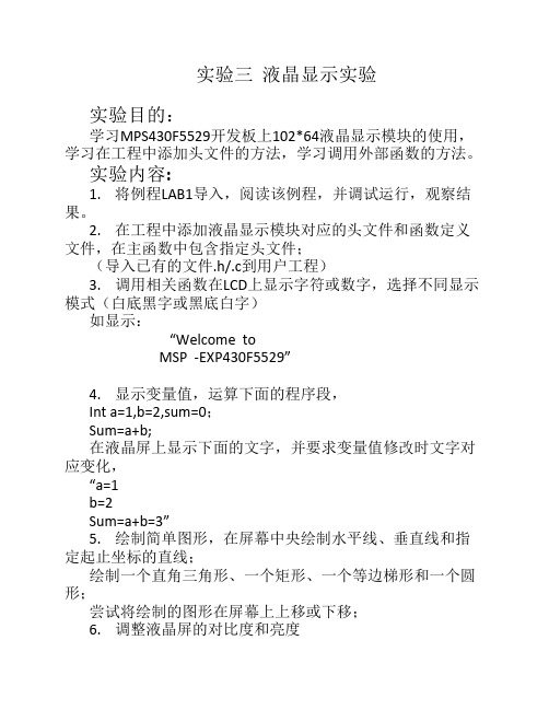
#include <REG52.H>sbit sclk = P0^0;sbit sdin = P0^1;sbit dc = P0^2;sbit sce = P0^3;sbit res = P0^4;unsigned char code hanzi[]={0};unsigned char code zifu[]={0x00,0x08,0xFC,0x00,0x00,0x00,0x00,0x02,0x03,0x02,0x00,0x00, //1 0x18,0x84,0x44,0x24,0x18,0x00,0x03,0x02,0x02,0x02,0x02,0x00, //20x08,0x04,0x24,0x24,0xD8,0x00,0x01,0x02,0x02,0x02,0x01,0x00, //3 0x40,0xB0,0x88,0xFC,0x80,0x00,0x00,0x00,0x00,0x03,0x02,0x00, //4 0x3C,0x24,0x24,0x24,0xC4,0x00,0x01,0x02,0x02,0x02,0x01,0x00, //5 0xF8,0x24,0x24,0x2C,0xC0,0x00,0x01,0x02,0x02,0x02,0x01,0x00, //6 0x0C,0x04,0xE4,0x1C,0x04,0x00,0x00,0x00,0x03,0x00,0x00,0x00, //7 0xD8,0x24,0x24,0x24,0xD8,0x00,0x01,0x02,0x02,0x02,0x01,0x00, //8 0x38,0x44,0x44,0x44,0xF8,0x00,0x00,0x03,0x02,0x02,0x01,0x00, //9 0xF8,0x04,0x04,0x04,0xF8,0x00,0x01,0x02,0x02,0x02,0x01,0x00, //00x00,0x40,0xA0,0xA0,0xC0,0x00,0x00,0x01,0x02,0x02,0x03,0x02, //a 0x04,0xFC,0x20,0x20,0xC0,0x00,0x00,0x03,0x02,0x02,0x01,0x00, //b 0x00,0xC0,0x20,0x20,0x60,0x00,0x00,0x01,0x02,0x02,0x02,0x00, //c 0x00,0xC0,0x20,0x24,0xFC,0x00,0x00,0x01,0x02,0x02,0x03,0x02, //d 0x00,0xC0,0xA0,0xA0,0xC0,0x00,0x00,0x01,0x02,0x02,0x02,0x00, //e 0x00,0x20,0xF8,0x24,0x24,0x04,0x00,0x02,0x03,0x02,0x02,0x00, //f0x00,0x40,0xA0,0xA0,0x60,0x20,0x00,0x07,0x0A,0x0A,0x0A,0x04, //g 0x04,0xFC,0x20,0x20,0xC0,0x00,0x02,0x03,0x02,0x00,0x03,0x02, //h 0x00,0x20,0xE4,0x00,0x00,0x00,0x00,0x02,0x03,0x02,0x00,0x00, //i0x00,0x00,0x20,0xE4,0x00,0x00,0x08,0x08,0x08,0x07,0x00,0x00, //j0x04,0xFC,0x80,0xE0,0x20,0x20,0x02,0x03,0x02,0x00,0x03,0x02, //k 0x04,0x04,0xFC,0x00,0x00,0x00,0x02,0x02,0x03,0x02,0x02,0x00, //l0xE0,0x20,0xE0,0x20,0xC0,0x00,0x03,0x00,0x03,0x00,0x03,0x00, //m 0x20,0xE0,0x20,0x20,0xC0,0x00,0x02,0x03,0x02,0x00,0x03,0x02, //n 0x00,0xC0,0x20,0x20,0xC0,0x00,0x00,0x01,0x02,0x02,0x01,0x00, //o 0x20,0xE0,0x20,0x20,0xC0,0x00,0x08,0x0F,0x0A,0x02,0x01,0x00, //p 0x00,0xC0,0x20,0x20,0xE0,0x00,0x00,0x01,0x02,0x0A,0x0F,0x08, //q 0x20,0xE0,0x40,0x20,0x20,0x00,0x02,0x03,0x02,0x00,0x00,0x00, //r0x00,0x60,0xA0,0xA0,0x20,0x00,0x00,0x02,0x02,0x02,0x03,0x00, //s 0x00,0x20,0xF8,0x20,0x00,0x00,0x00,0x00,0x01,0x02,0x02,0x00, //t0x20,0xE0,0x00,0x20,0xE0,0x00,0x00,0x01,0x02,0x02,0x03,0x02, //u0x20,0xE0,0x20,0x80,0x60,0x20,0x00,0x00,0x03,0x01,0x00,0x00, //v0x60,0x80,0xE0,0x80,0x60,0x00,0x00,0x03,0x00,0x03,0x00,0x00, //w0x20,0x60,0x80,0x60,0x20,0x00,0x02,0x03,0x00,0x03,0x02,0x00, //x0x20,0xE0,0x20,0x80,0x60,0x20,0x08,0x08,0x07,0x01,0x00,0x00, //y0x00,0x20,0xA0,0x60,0x20,0x00,0x00,0x02,0x03,0x02,0x02,0x00, //z};void delay(unsigned int ms)//1ms延时函数{unsigned int i,x;for(x=0;x<ms;x++){for(i=0;i<100;i++);}}void LCD_DC(unsigned char dt, unsigned char command)//写指令0写数据1 dt:写的内容;{unsigned char i;sce=0; //5110使能dc=command; //通过command(=dc)来控制是写指令(0)还是写数据(1)if (command == 0) //写命令sdin = 0; //串口关使能else sdin = 1; //写数据,串口使能for(i=0;i<8;i++)//8位数据{if(dt&0x80) //写入的东西从高位开始读sdin=1; //串口使能else sdin=0; //其他关串口使能sclk=0; //CP0dt=dt<<1; //让指令依次左移使之读出sclk=1; //CP1}dc=1; //写数据sce=1; //关使能sdin=1; //串口开}void LCDchushi(void)//初始化{res=0; //0 使复位delay(10);res=1; //关复位sce=0;delay(10);sce=1;delay(10);LCD_DC(0x21,0);//初始化Lcd,功能设定使用扩充指令0写指令LCD_DC(0xC6,0);//设定液晶偏置电压0写指令LCD_DC(0x06,0);//温度校正0写指令LCD_DC(0x13,0);;//1:48 0写指令LCD_DC(0x20,0);//使用基本指令0写指令LCD_DC(0x0C,0);//设定显示模式,正常显示0写指令}void LCD_set_XY(unsigned char X, unsigned char Y){LCD_DC(0x40|Y, 0);// column 0100 0000 0写指令 0x40|Y?可能是指令集中设置行的指令LCD_DC(0x80|X, 0);// row 1000 0000 0写指令 0x80|X?可能是指令集中设置列的指令}void LCD_clear(void) //清屏函数{unsigned char t;unsigned char k;LCD_set_XY(0,0);//光标初始为左上角for(t=0;t<6;t++)//行{for(k=0;k<84;k++)//列{LCD_DC(0x00,1); //写数据0x00 清空}}}void write_zifu(unsigned char row, unsigned char page,unsigned char c) //row:列page:页dd:字符{unsigned char i;LCD_set_XY(row*6, page);for(i=0; i<6;i++) LCD_DC(zifu[c*12+i],1);LCD_set_XY(row*6, page+1);for(i=6; i<12;i++) LCD_DC(zifu[c*12+i],1);}void write_hanzi(unsigned char row, unsigned char page,unsigned char c) //row:列page:页c:字符{unsigned char i;LCD_set_XY(row*6, page);for(i=0; i<12;i++) LCD_DC(hanzi[c*24+i],1);LCD_set_XY(row*6, page+1);// 列,页for(i=12; i<24;i++) LCD_DC(hanzi[c*24+i],1);}void main(void){sce=0;res=0;delay(1);res=1;LCDchushi();LCD_clear();write_zifu(0,0,0);write_zifu(1,0,1);write_zifu(2,0,2);write_zifu(3,0,3);write_zifu(4,0,4);write_zifu(5,0,5);write_zifu(6,0,6);write_zifu(7,0,7);write_zifu(8,0,8);write_zifu(9,0,9);write_zifu(10,0,0);write_zifu(11,0,1);write_zifu(12,0,2);write_zifu(13,0,3);while(1){}。
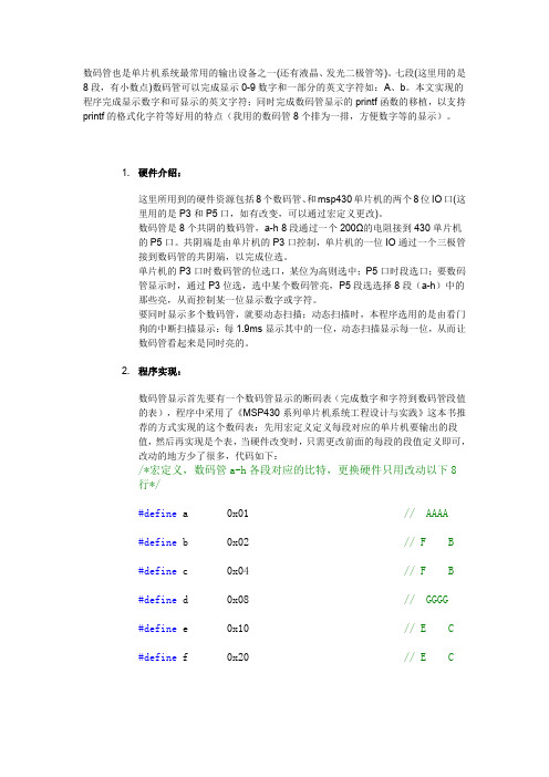
数码管也是单片机系统最常用的输出设备之一(还有液晶、发光二极管等)。
七段(这里用的是8段,有小数点)数码管可以完成显示0-9数字和一部分的英文字符如:A、b。
本文实现的程序完成显示数字和可显示的英文字符;同时完成数码管显示的printf函数的移植,以支持printf的格式化字符等好用的特点(我用的数码管8个排为一排,方便数字等的显示)。
1.硬件介绍:这里所用到的硬件资源包括8个数码管、和msp430单片机的两个8位IO口(这里用的是P3和P5口,如有改变,可以通过宏定义更改)。
数码管是8个共阴的数码管,a-h8段通过一个200Ω的电阻接到430单片机的P5口。
共阴端是由单片机的P3口控制,单片机的一位IO通过一个三极管接到数码管的共阴端,以完成位选。
单片机的P3口时数码管的位选口,某位为高则选中;P5口时段选口;要数码管显示时,通过P3位选,选中某个数码管亮,P5段选选择8段(a-h)中的那些亮,从而控制某一位显示数字或字符。
要同时显示多个数码管,就要动态扫描;动态扫描时,本程序选用的是由看门狗的中断扫描显示:每1.9ms显示其中的一位,动态扫描显示每一位,从而让数码管看起来是同时亮的。
2.程序实现:数码管显示首先要有一个数码管显示的断码表(完成数字和字符到数码管段值的表),程序中采用了《MSP430系列单片机系统工程设计与实践》这本书推荐的方式实现的这个数码表:先用宏定义定义每段对应的单片机要输出的段值,然后再实现是个表,当硬件改变时,只需更改前面的每段的段值定义即可,改动的地方少了很多,代码如下:/*宏定义,数码管a-h各段对应的比特,更换硬件只用改动以下8行*/#define a0x01//AAAA#define b0x02//F B#define c0x04//F B#define d0x08//GGGG#define e0x10//E C#define f0x20//E C#define g0x40//DDDD HH#define h0x80//小数点/*用宏定义自动生成段码表,很好的写法,值得学习*//*更换硬件无需重写段码表*/const char Tab[]={a+b+c+d+e+f,//Displays"0"b+c,//Displays"1"a+b+d+e+g,//Displays"2"a+b+c+d+g,//Displays"3"b+c+f+g,//Displays"4"a+c+d+f+g,//Displays"5"a+c+d+e+f+g,//Displays"6"a+b+c,//Displays"7"a+b+c+d+e+f+g,//Displays"8"a+b+c+d+f+g,//Displays"9"a+b+c+e+f+g,//Displays"A"c+d+e+f+g,//Displays"B"a+d+e+f,//Displays"C"b+c+d+e+g,//Displays"D"a+d+e+f+g,//Displays"E"a+c+d+e+f,//Displays"G" b+c+e+f+g,//Displays"H" e+f,//Displays"I" b+c+d+e,//Displays"J" b+d+e+f+g,//Displays"K" d+e+f,//Displays"L" a+c+e+g,//Displays"M" a+b+c+e+f,//Displays"N" c+e+g,//Displays"n" c+d+e+g,//Displays"o" a+b+c+d+e+f,//Displays"O" a+b+e+f+g,//Displays"P" a+b+c+f+g,//Displays"Q" e+g,//Displays"r" a+c+d+f+g,//Displays"S" d+e+f+g,//Displays"t" a+e+f,//Displays"T" b+c+d+e+f,//Displays"U" c+d+e,//Displays"v" b+d+f+g,//Displays"W" b+c+d+f+g,//Displays"Y"g,//Displays"-"h,//Displays"."0//Displays"" };#undef a#undef b#undef c#undef d#undef e#undef f#undef g0-9的位置对应显示0-9,之后的是A开始往后显示,为了方便访问这个表格,定义了AA等一系列的常量,方便访问这个表。

MSP430单⽚机和LCD模块在显⽰终端中的应⽤(1)3 结语该系统已在邯郸马头电⼚投⼊使⽤,运营正常。
该系统将⽕车接近提⽰报警系统和铁⽜拉车及推车系统连成⼀体,使卸煤线安全监控得到了很好的保证,有效地杜绝了卸煤线进车、调车的不安全现象,完善了⽕车接近智能监控系统,实现了安全管理的信息化。
参考⽂献:[1] 宋伯⽣.PL C编程实⽤指南[M].北京:机械⼯业出版社,2006.[2] 李国厚.PL C原理与应⽤设计[M].北京:化学⼯业出版社,2005.[3] 余成波,胡新宇,赵 勇.传感器与⾃动检测技术[M].北京:⾼等教育出版社,2004.[4] 张凯峰.西门⼦S7-200在⾁类⼯业杀菌⼯艺⾃动控制系统的应⽤[J].电⽓应⽤,2005(24).[5] 张铁壁.⽕车临近报警系统的设计[J].河北⼯程技术⾼等专科学校学报,2004(1).[6] 欧阳三泰.PL C控制系统⾃动报警程序的设计⽅法[D].湘潭:湖南⼯程学院,2004.[7] 苏成斌.输煤程控系统的设计[D].⼤庆:⼤庆⽯油学院,2003. 第3期 2008年6⽉⼯矿⾃动化 Industry and Mine Automation No.3 J un.2008 ⽂章编号:1671-251X(2008)03-0116-03MSP430单⽚机和LCD模块在显⽰终端中的应⽤3陆靓亮, 冯⼩龙, 钱建⽣, 武⾦磊, 张兴华, 王鸿建(中国矿业⼤学信电学院,江苏徐州 221008)摘要:⽂章阐述了MSP430单⽚机和L CD显⽰模块的特点和功能,介绍了⼀种以MSP430F147为核⼼、OCMJ2×10C为液晶显⽰模块的显⽰终端的设计⽅法,给出了显⽰终端典型的硬件应⽤电路和液晶显⽰流程图。
实际应⽤表明,该应⽤电路功耗低,运⾏稳定。
关键词:显⽰终端;液晶模块;超低功耗;单⽚机;MSP430F147中图分类号:T D672;TP334.1 ⽂献标识码:B0 引⾔传统的显⽰终端通常以普通的51单⽚机为核⼼、L ED数码管为显⽰模块,但普通51单⽚机的体积⼤、功耗⾼,L ED的⼈机对话效果差。
使用MSP430设计系统监控器MSP430是一种低功耗的微控制器,适合用于设计系统监控器。
在本文中,将详细介绍如何使用MSP430设计一个功能齐全的系统监控器。
首先,我们需要选择一个合适的MSP430系列微控制器。
MSP430系列中有多个不同型号可供选择,其中一些具有特定的功能和性能。
我们需要根据我们的系统监控器的需求来选择一个适当的型号。
接下来,我们需要设计电路图。
系统监控器通常包括多个传感器,如温度传感器、湿度传感器、光照传感器等,以及一些输出设备,如显示屏、蜂鸣器等。
我们需要将这些组件与MSP430微控制器连接起来,并确保电路图的正确性和可靠性。
在完成电路图设计后,我们可以使用相应的软件工具进行电路模拟和仿真。
这可以帮助我们验证电路的功能和性能,并进行必要的调整和改进。
然后,我们需要编写软件代码。
MSP430系列微控制器通常使用C语言进行编程。
我们可以使用开发套件中提供的IDE(集成开发环境)来编写和调试代码。
在编写代码时,我们需要考虑以下几个方面:1.设置传感器和输出设备的接口。
我们需要了解每个设备连接到MSP430微控制器的引脚,并设置相应的GPIO(通用输入/输出)配置。
2.编写数据采集和处理代码。
我们需要使用传感器读取数据,并进行适当的数据处理和计算。
例如,我们可以使用温度传感器读取当前温度,并根据一些预定的阈值判断是否需要触发警报。
3.确定监控指标和警报阈值。
我们需要明确监控的指标,例如温度、湿度等,并设置相应的警报阈值。
当监测的指标超过或低于设定的阈值时,系统应该触发相关的警报。
4.设计用户界面。
系统监控器通常需要一个用户界面来显示监测的数据和警报信息。
我们可以使用MSP430的显示屏来设计一个简单的用户界面,并将数据以易理解的方式显示出来。
5.调试和测试。
在完成编写代码后,我们需要使用调试工具对代码进行调试,并测试系统监控器的各项功能。
在测试过程中,我们可以使用虚拟传感器输入模拟不同的条件,并验证系统的相应。

5110LCD小板原理图:不妥的地方请指出1.增加了74HC165,在不增加任何I/O口的情况下提供8个按键2.板载LCD阻容复位,LCD_reset可以外部控制也可以阻容复位3.背光可以控制4.最少4个I/O端口就可以控制液晶和读取8个按键不放心,按照上图接线进行实物测试结果通过,程序如下:$Device= m16 使用mega16$Stack = 32 堆栈32字节$Clock = 4 时钟4MHz$ShiftOut Data=PORTB.5 ,Clk=PORTB.7,Msb 申明一个简易SPI口$GLCD Nokia3310, SCLK=PORTB.7, SDIN=PORTB.5, DC=PORTB.1, SCE=PORTB.4 3310液晶连接定义$Def RES=PORTB.0 复位脚$LeadChar=" ", Format(3,0) 显示数据格式化$Def SL = PORTB.1 去74HC165锁存$Def led = PORTB.3 去3310背光控制Dim n_key As Byte 保存按键键值Dim n As Byte 显示一个变量n好观察3310有没有运行Dim F0HD As Flash Byte 英文字库F0HDn_key=255Set DDRB.0: Nop 3: Set RES 复位3310LCDSet DDRB.3Reset led 点亮3310背光灯GLcdInit 初始化3310LCDFontSet F0HD 选择字体GLcd(0,5),"" 显示一个字符串DoGLcd(0,2),"key=";n_key 显示键值GLcd(60, 0), n 显示一个变量n好观察3310有没有运行Incr nReset SLSet SL 锁存74HC165Reset DDRB.5 将SDIN变为输入为读取74HC165做准备Set DDRB.7n_key=ShiftIn 获得键值n_key=Not n_keyWaitMs 100Set DDRB.5 将SDIN变为输出为写3310LCD做准备Loop$Include "C:\FastAVR\Nokia3310\F0HD.bas"图片附件:该帖子在2006-1-7 0:26:48 编辑过本站有售:30元/片Nokia 3310手机的点阵LCD模块不仅小巧、省电、驱动容易,而且价钱也便宜。
程序功能:在LCD屏幕第一行第一列显示字符A端口:P1——DB0~DB7P2.0——RSP2.1——RWP2.2——EN****************************************************/#inlude<AT89x51.h>#define LCD_DB P1sbit LCD_RS=P2^0;sbit LCD_RW=P2^1;sbit LCD_E=P2^2;#define uchar unsigned char#define uint unsigned intvoid LCD_init(void);void LCD_write_command(uchar command);void LCD_write_data(uchar dat);void LCD_disp_char(uchar x,uchar y,uchar dat);void LCD_check_busy(void);void delay_n40us(uint n);/***************************************************函数名称:LCD_init函数功能:初始化LCD***************************************************/void LCD_init(void){//设置数据总线为8位,2行显示,5*7点阵/每字符——————功能设定LCD_write_command(0x38);//显示功能开,无光标,光标闪烁——————显示控制LCD_write_command(0x0c);//写入数据后光标右移——————模式设置LCD_write_command(0x06);//清除屏幕——————清屏指令LCD_write_command(0x01);delay_n40us(100);//延时一段时间保证完全清屏}/***************************************************函数名称:LCD_write_command函数功能:void LCD_write_command(uchar command){LCD_DB=command;//向P1端口写入指令LCD_RW=0;//设置为向LCD写入指令或数据LCD_RS=0;//设置为输入指令模式LCD_E=1;//允许写入LCD_E=0;//结束写入delay_n40us(1);}/*************************************************** 函数名称:LCD_write_data函数功能:写入字符数据***************************************************/ void LCD_write_data(uchar dat){LCD_DB=dat;//向P1端口写入数据LCD_RW=0;LCD_RS=1;//设置为写入数据模式LCD_E=1;LCD_E=0;delay_n40us(1);}/*************************************************** 函数名称:LCD_disp_char函数功能:显示一个字符***************************************************/ void LCD_disp_char(uchar x,uchar y,uchar dat){uchar address;if(y==1) address=0x80+x;//如果是第一行,则地址为?else address=0xc0+x;//如果是第二行,则地址为?LCD_write_command(address);LCD_write_data(dat);}/*************************************************** 函数名称:LCD_check_busy函数功能:忙检测***************************************************/ void LCD_check_busy(void){ do{LCD_E=0;LCD_RS=0;LCD_RW=1;LCD_DB=0xff;//P1端口设置为高电平LCD_E=1;}while(LCD_DB^7==1);}/********************************************** 函数名称:delay_n40us函数功能:延时**********************************************/ void delay_n40us(uint n){ uint i;uint j;for(i=n,i>0;i++)for(j=0;j<2;j++);}/**************主函数*************************/ void main(){ LCD_init();LCD_dis_char(0,1,"A");while(1);}。
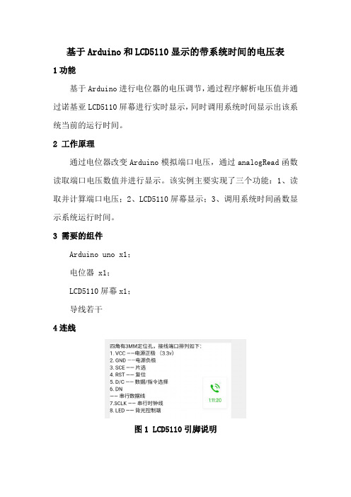
基于Arduino和LCD5110显示的带系统时间的电压表1功能基于Arduino进行电位器的电压调节,通过程序解析电压值并通过诺基亚LCD5110屏幕进行实时显示,同时调用系统时间显示出该系统当前的运行时间。
2 工作原理通过电位器改变Arduino模拟端口电压,通过analogRead函数读取端口电压数值并进行显示。
该实例主要实现了三个功能:1、读取并计算端口电压;2、LCD5110屏幕显示;3、调用系统时间函数显示系统运行时间。
3 需要的组件Arduino uno x1;电位器 x1;LCD5110屏幕x1;导线若干4连线图1 LCD5110引脚说明图2 电路连接示意图5完整代码#include <LCD5110_Basic.h> //注意使用Arduino IDE1.0环境开发LCD5110 myGLCD(3,4,5,6,7);extern uint8_t SmallFont[];//声明字体函数unsigned long millis();//声明获取系统时间函数float num;//定义电压值存储变量为浮点型数据int potpin=0; //定义模拟接口0int val=0; //将定义变量val,并赋初值0int v;//映射转换电压void setup(){myGLCD.InitLCD(); //Intializing LCD}void loop(){val=analogRead(potpin); //读取模拟接口0 的值,并将其赋给valv=map(val,0,1023,0,500);num=(float)v/100.00;myGLCD.setContrast(60); //设置对比度myGLCD.setFont(SmallFont);myGLCD.print("The Voltage :",LEFT,0); //暂不支持汉字字符myGLCD.printNumF(num, 2,CENTER,16); //显示保留小数点后两位的数,位点是8的整数倍有效myGLCD.print("V",RIGHT,16);myGLCD.print("System Time",RIGHT,32);myGLCD.printNumI(millis()/1000, RIGHT,40); //计时系统运行时间,单位sdelay(1000);myGLCD.clrScr();}6 实物成品运行效果。

创作编号:BG7531400019813488897SX创作者:别如克*自动量程数字万用表(B题)摘要全文主要介绍了基于STM32F103RBT6的自动量程数字万用表的设计。
本设计以STM32F103RBT6作为核心MCU,配合外围的各个模块,实现了交流电压、直流电压、频率、电阻以及电流的高精度测量,同时具有自动更换量程功能。
所测得值在LCD5110液晶显示屏上显示,整个仪器完全由一节1.5V 一号电池供电,达到了低功耗的目的。
关键词:STM32单片机,AD736,自动量程转换,升压模块一.方案设计与论证1.1 MCU的选择方案一:MSP430系列单片机MSP430系列单片机是美国德州公司(TI)1996年开始推向市场一种16位超低功耗、具有精简指令集SC)的混合信号处理器(Mixed Signal Processor)。
称之为混合信号处理器,是由于其针对实际应用需求,将多个不同功能的模拟电路、数字电路模块和微处理器集成在一个芯片上,以提供“单片”解决方案。
该系列单片机多应用于需要电池供电的便携式仪器仪表中。
具有处理能力强、运算速度快、超低功耗、片内资源丰富的优点。
方案二:51系列单片机51单片机是对目前所有兼容Intel 8031指令系统的单片机的统称。
该系列单片机的始祖是Intel的8031单片机,后来随着Flash rom技术的发展,8031单片机取得了长足的进展,成为目前应用最广泛的8位单片机之一,其代表型号是ATMEL公司的AT89系列,它广泛应用于工业测控系统之中。
目前很多公司都有51系列的兼容机型推出,在目前乃至今后很长的一段时间内将占有大量市场。
51单片机是基础入门的一个单片机,还是应用最广泛的一种。
方案三:STM32系列单片机由于STM32F103RBT6的时钟频率达到72 MHz,能实现高端运算。
内嵌128KB FLASH 程序存储器。
丰富的外设,UART、SPI等串行接口以及最大翻转率18 MHz的GPIO。


基于MSP430的LED数码管显示电路设计LED数码管显示电路是一种常见的电路应用,用于显示数字和字符等信息。
本文基于MSP430微控制器设计了一个LED数码管显示电路,主要包括芯片选择、数码管选择、驱动电路设计、显示电路设计等方面。
首先,在芯片选择上,我们选择了MSP430微控制器。
MSP430是德州仪器(Texas Instruments)的一种低功耗单片机,具有强大的计算和控制能力,适合用于各种应用场景。
我们选择MSP430主要考虑了其低功耗特性和易于编程的特点。
接下来,在数码管选择上,我们选择了常见的共阳极数码管。
共阳极数码管的特点是具有共阳极,即所有的阳极连接在一起,并通过操控各个阴极的状态来实现显示。
选择共阳极数码管的主要原因是其易于控制和接口。
然后,在驱动电路设计上,我们采用B脚驱动方式。
B脚驱动方式是指通过控制数码管的B脚(即常导极)来操控各个阴极的状态。
具体实现方法是将B脚通过一个电流放大器连接到MSP430微控制器的一个输出引脚上,通过控制输出引脚的高低电平来控制B脚的导通和断开。
最后,在显示电路设计上,我们采用了逐位显示的方式。
逐位显示是指依次将要显示的数字或字符通过MSP430微控制器的输出引脚分别连接到数码管的各个阴极上,通过快速切换各个阴极的状态来实现数字的显示。
具体实现方法是通过设置MSP430微控制器的输出引脚序列和各个数码管阴极的连接关系,实现数字的逐位显示。
总结起来,基于MSP430的LED数码管显示电路设计主要包括芯片选择、数码管选择、驱动电路设计、显示电路设计等方面。
通过选择适合的硬件平台和驱动方式,结合MSP430微控制器的强大功能和易于编程的特点,我们可以设计出一个稳定可靠、易于控制和显示的LED数码管显示电路。
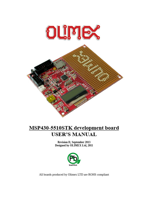
MSP430-5510STK development board USER’S MANUALRevision D, September 2013Designed by OLIMEX Ltd, 2011All boards produced by Olimex LTD are ROHS compliantDisclaimer:© 2013 Olimex Ltd. Olimex®, logo and combinations thereof, are registered trademarks of Olimex Ltd. Other terms and product names may be trademarks of others.The information in this document is provided in connection with Olimex products. No license, express or implied or otherwise, to any intellectual property right is granted by this document or in connection with the sale of Olimex products.Neither the whole nor any part of the information contained in or the product described in this document may be adapted or reproduced in any material from except with the prior written permission of the copyright holder.The product described in this document is subject to continuous development and improvements. All particulars of the product and its use contained in this document are given by OLIMEX in good faith. However all warranties implied or expressed including but not limited to implied warranties of merchantability or fitness for purpose are excluded. This document is intended only to assist the reader in the use of the product. OLIMEX Ltd. shall not be liable for any loss or damage arising from the use of any information in this document or any error or omission in such information or any incorrect use of the product.This evaluation board/kit is intended for use for engineering development, demonstration, or evaluation purposes only and is not considered by OLIMEX to be a finished end-product fit for general consumer use. Persons handling the product must have electronics training and observe good engineering practice standards. As such, the goods being provided are not intended to be complete in terms of required design-, marketing-, and/or manufacturing-related protective considerations, including product safety and environmental measures typically found in end products that incorporate such semiconductor components or circuit boards.Olimex currently deals with a variety of customers for products, and therefore our arrangement with the user is not exclusive. Olimex assumes no liability for applications assistance, customer product design, software performance, or infringement of patents or services described herein.THERE IS NO WARRANTY FOR THE DESIGN MATERIALS AND THE COMPONENTS USED TO CREATE MSP430-5510STK. THEY ARE CONSIDERED SUITABLE ONLY FOR MSP430-5510STK. Thank you for purchasing MSP430-5510STK development board assembled by OLIMEX LTD.Table of ContentsCHAPTER 1: OVERVIEW (5)1. Introduction to the chapter (5)1.1 Features (5)1.2 Organization (5)CHAPTER 2: SETTING UP THE MSP430-5510STK BOARD (7)2. Introduction to the chapter (7)2.1 Electrostatic warning (7)2.2 Requirements (7)2.3 Powering the board (7)2.4 Prebuilt software (8)2.5 Bootloader mode (8)CHAPTER 3: MSP430-5510STK BOARD DESCRIPTION (9)3. Introduction to the chapter (9)3.1 Layout (top view) (9)CHAPTER 4: THE MSP430F5510 MICROCONTROLLER (10)4. Introduction to the chapter (10)4.1 The microcontroller (10)CHAPTER 5 CONTROL CIRCUITY (11)5. Introduction to the chapter (11)5.1 Reset (11)5.2 Clocks (11)CHAPTER 6: HARDWARE (12)6. Introduction to the chapter (12)6.1 Battery connector (12)6.2 JTAG connector (12)6.3 UEXT (13)6.4 Pads on the proto area (14)6.5 USB mini connector (15)6.6 SD/MMC slot (15)6.7 Jumper description (15)6.8 LCD Display (16)6.9 Additional hardware components (17)CHAPTER 7: MEMORY AND BLOCK DIAGRAM (18)7. Introduction to the chapter (18)7.1 Memory organization (18)CHAPTER 8: SCHEMATICS (19)8. Introduction to the chapter (19)8.1 Eagle schematic (19)8.2 Physical dimensions (21)CHAPTER 9: REVISION HISTORY (22)9. Introduction to the chapter (22)9.1 Document revision (22)9.2 Web page of your device (23)9.3 Product support (24)CHAPTER 1: OVERVIEW1. Introduction to the chapterThank you for choosing the MSP430-5510STK development board from Olimex! This document provides a User’s Guide for the Olimex MSP430-5510STK development board. As an overview, this chapter gives the scope of this document and lists the board’s features. The document’s organization is then detailed.The MSP430-5510STK development board enables code development of applications running on the MSP430F5510 microcontroller, manufactured by Texas Instruments.1.1 Features•MCU MSP430F5510 with 32K Bytes Program Flash, 4K Bytes RAM, 25Mhz LCD display8 alphanumeric•micro SD card connector•Li-Po battery on-board charger•USB connector, and USB bootloader support•two buttons• 2 status LEDs•access to every pin near prototype area•Reset button•UEXT connector that allows other Olimex's modules (MOD-MP3, MOD-NRF24L01, etc.) to be connected•JTAG connector•JTAG Power_In and Power_Out jumpers•32 768 Hz oscillator crystal• 4 Mhz crystall oscillator•Power supply voltage regulators and filtering capacitor•Power on Led•PCB: FR-4, 1.5 mm (0,062"), soldermask, white silkscreen component print•Dimensions: 100x 80mm (3.94x 3.14")1.2 OrganizationEach section in this document covers a separate topic, organized as follow:–Chapter 1 is an overview of the board usage and features–Chapter 2 provides a guide for quickly setting up the board–Chapter 3 contains the general board diagram and layout–Chapter 4 describes the component that is the heart of the board: the MSP430F5510 microcontroller–Chapter 5 is an explanation of the control circuitry associated with the microcontroller to reset. Shows the clocks located on the board.–Chapter 6 covers the connector pinout, peripherals and jumper description –Chapter 7 shows the processor diagram and memory map–Chapter 8 provides the schematics–Chapter 9 contains the revision historyCHAPTER 2: SETTING UP THE MSP430-5510STK BOARD2. Introduction to the chapterThis section helps you set up the MSP430-5510STK development board for the first time.Please consider first the electrostatic warning to avoid damaging the board, then discover the hardware and software required to operate the board.The procedure to power up the board is given, and a description of the default board behavior is detailed.2.1 Electrostatic warningMSP430-5510STK is shipped in a protective anti-static package. The board must not be exposed to high electrostatic potentials. A grounding strap or similar protective device should be worn when handling the board. Avoid touching the component pins or any other metallic element.2.2 RequirementsIn order to set up the MSP430-5510STK, the following items are required:- A source of power – the board can be powered through the mini USB connector (standard 5V), through the JTAG connector (by the debugger/programmer) or via a 3.7Li-Po battery.- Programmer supporting 14 pin JTAG interface and the used microcontroller MSP430F5510.All our MSP programmers are recommended with MSP430-5510STK:- Olimex MSP430-JTAG-TINY-V2 - mini emulator/programmer USB<->JTAG 14p with powering capabilities- Olimex MSP430-JTAG-ISO-MK2 – emulator/debugger with additional stand-alone read/write mode, power profiling and software support for most MSP430 integrated environments and operating systems.Additionally any MSP430 compatible debugger should be compatible with the 14p connector of the board. The MSP430F5510 microcontroller lacks SWD interface.Also, a host-based software toolchain is required in order to program/debug the MSP430-5510STK board. There are also a number of ready IDEs available like IAR Embedded Workbench,Rowley CrossWorks, Code Composer Studio, etc.We also provide our own flash programming software which can be distributed free. You can find it at the device web page.2.3 Powering the boardThere are three ways of powering the board: via the USB; via the debugger from the JTAG connector or via a 3.7V Li-Po battery connected to the respective connector.-Plug mini USB with at least 5V to the board OR connect a charged 3.7V Li-Po battery to the respective connectorOR-Set the jumpers P_IN closed, P_OUT open so you can power from JTAG connectorOn powering the board via USB the PWR LED, LED1 and the display should turn on.On powering the board via JTAG the LED1 and the display should turn on.The board has a Li-Po charger. This means that when a Li-Po battery is plugged in the battery connector and there is additional source of power applied (USB or JTAG) the battery will begin to charge (making the overall current draw of the board higher).2.4 Prebuilt softwareOn powering the board via the USB the PWR LED should turn on. The LED1 should blink green and the LCD should show the message: “OLIMEX”.2.5 Bootloader modeTo enter bootloader mode press USB_BSL button and then plug the board. You will also need the correct bootloader software which is available at Texas Instruments web site in the USB Developer Package. We have tested MSP430_USB_Firmware_Upgrade_Example-1.2.1-Setup.exe.CHAPTER 3: MSP430-5510STK BOARD DESCRIPTION3. Introduction to the chapterHere you get acquainted with the main parts of the board. Note the names used on the board differ from the names used to describe them. For the actual names check the MSP430-5510STK board itself.3.1 Layout (top view)CHAPTER 4: THE MSP430F5510 MICROCONTROLLER4. Introduction to the chapterIn this chapter is located the information about the heart of MSP430-5510STK – its microcontroller. The information is a modified version of the datasheet provided by its manufacturers.4.1 The microcontrollerMain processors features:•Low Supply-V oltage Range, 1.8 V to 3.6 V•Ultra-Low Power Consumption✗Active Mode (AM)All System Clocks Active:- 195 µA/MHz at 8 MHz, 3 V, Flash Program Execution (Typical)- 115 µA/MHz at 8 MHz, 3 V, RAM Program Execution (Typical)✗Standby Mode (LPM3)- Real Time Clock With Crystal, Watchdog, and Supply Supervisor Operational,Full RAM Retention, Fast Wake-Up: 1.9 µA at 2.2 V, 2.1 µA at 3 V (Typical)- Low-Power Oscillator (VLO), General-Purpose Counter, Watchdog, and SupplySupervisor Operational, Full RAM Retention, Fast Wake-Up: 1.4 µA at 3 V (Typical)✗Off Mode (LPM4)Full RAM Retention, Supply Supervisor Operational, Fast Wake-Up: 1.1 µA at 3 V(Typical)✗Shutdown Mode (LPM4.5)0.18 µA at 3 V (Typical)•Wake-Up From Standby in Less Than 5 µs•16-Bit RISC Architecture, Extended Memory, Up to 25-MHz System Clock•Flexible Power Management System✗Fully Integrated LDO With Programmable Regulated Core Supply V oltage✗Supply V oltage Supervision, Monitoring, and Brownout•Unified Clock System:✗FLL Control Loop for Frequency Stabilization✗Low-Power Low-Frequency Internal Clock Source (VLO)✗Low-Frequency Trimmed Internal Reference Source (REFO)✗32-kHz Watch Crystals (XT1)For comprehensive information on the microcontroller visit the Texas Instruments web page for a datasheet.At the moment of writing the microcontroller datasheet can be found at the following link:/lit/ds/slas645f/slas645f.pdfCHAPTER 5 CONTROL CIRCUITY5. Introduction to the chapterHere you can find information about reset circuit, power circuit and quartz crystal locations.5.1 ResetMSP430-5510STK reset circuit includes R7 (33 KΩ), R8(330 Ω), MSP430F5510 pin 48 (RST/NMI/SBWTTDIO) and a RESET button.5.2 ClocksReal time clock (RTC) Q1 is connected to pins 8 and 9 of the processor.4 MHz quarz crystal Q2 is found at pins 45 and 46 of the processor.CHAPTER 6: HARDWARE6. Introduction to the chapterIn this chapter are presented the connectors that can be found on the board all together with their pinout. Proto area is shown. Jumpers functions are described. Notes and info on specific peripherals are presented. Notes regarding the interfaces are given.6.1 Battery connectorThe battery connector is used only to charge 3.7V Lithium batteries. It cannot be used to power the board.6.2 JTAG connectorThe 14 pin JTAG connector provides the interface for JTAG programming/debugging. The pinout can be found in the table below.6.3 UEXTMSP430-5510STK board has UEXT connector and can interface Olimex's UEXT modules. For more information on UEXT please visit:https:///Products/Modules/UEXT/6.4 Pads on the proto areaFor your convenience the pads are named individually near each of them. Please take extra care about the numbering but consider that there might be offset.6.5 USB mini connector6.6 SD/MMC slot6.7 Jumper descriptionP_OUT/P_INThis jumper controls power on pins 2 and 4 of the JTAG connector. When in P_OUT is closed 3.3V can be measured at pin 4.Check the schematic for more info.Default position is P_OUT – closed, P_IN - open.3.3V_JPIf open open stops processor and proto area pads powering.Default state is closed.SW_SCL/HW_SCL; SW_SDA/HW_SDAThese two jumpers control whether the SCL and SDA signals to be implemented on software or hardware level. When in position SW_SCL/SW_SDA software implementation.Default position is SW_SCL; SW_SDA.CHG_DIf closed stops the battery charger.Default state is open.AGND_EAnalog GND is disabled if open.If closed Analog GND is enabled.Default state is closed.6.8 LCD Display8 characters alphanumeric LCD display.6.9 Additional hardware componentsThe components below are mounted on MSP430-5510STK but are not discussed above. They are listed here for completeness:2 buttons + RST buttonLED + power-on LEDCHAPTER 7: MEMORY AND BLOCK DIAGRAM7. Introduction to the chapterBelow is located the block diagram of the processor and on the next page you can find a memory map for this family of processors. It is strongly recommended to refer to the original datasheet released by Texas Instruments for ones of higher quality.7.1 Memory organizationCHAPTER 8: SCHEMATICS8. Introduction to the chapterIn this chapter are located the schematics describing logically and physically MSP430-5510STK.8.1 Eagle schematicMSP430-5510STK schematic is visible for reference here. You can also find them on the web page for MSP430-5510STK at our site: https:///Products/MSP430/Starter/MSP430-5510STK/. They are located in HARDWARE section.The EAGLE schematic is situated on the next page for quicker reference.OLIMEX© 2012MSP430-5510STK user's manualPage 20 of 248.2 Physical dimensionsNote that all dimensions are in inches.CHAPTER 9: REVISION HISTORY9. Introduction to the chapterIn this chapter you will find the current and the previous version of the document you are reading. Also the web-page for your device is listed. Be sure to check it after a purchase for the latest available updates and examples.9.1 Document revision9.2 Web page of your deviceThe web page you can visit for more info on your device ishttps:///Products/MSP430/Starter/MSP430-5510STK/. There you can find more info and some examples.ORDER CODES:MSP430-5510STK - completely assembled and testedMSP430-JTAG-TINY-V2 - mini emulator/programmer USB<->JTAG 14p with powering capabilitiesMSP430-JTAG-ISO-MK2 – emulator/debugger with additional stand-alone read/write mode, power profiling and software support for most MSP430 integrated environments and operating systemsHow to order?You can order directly from our web-shop or via any of our distributors.Check our webpage https:/// for more info.9.3 Product supportFor product support, hardware information and error reports mail to: ******************. All document or hardware feedback is welcome. Note that we are primarily a hardware company and our software support is limited. Please consider reading the paragraph below about the warranty of Olimex products.All goods are checked before they are sent out. In the unlikely event that goods are faulty, they must be returned, to OLIMEX at the address listed on your order invoice.OLIMEX will not accept goods that have clearly been used more than the amount needed to evaluate their functionality.If the goods are found to be in working condition, and the lack of functionality is a result of lack of knowledge on the customers part, no refund will be made, but the goods will be returned to the user at their expense.******************************************************************************* number before shipping back any merchandise. Please include your name, phone number and order number in your email request.Returns for any unaffected development board, programmer, tools, and cables permitted within 7 days from the date of receipt of merchandise. After such time, all sales are considered final.Returns of incorrect ordered items are allowed subject to a10%restocking fee.What is unaffected? If you hooked it to power, you affected it. To be clear, this includes items that have been soldered to,or have had their firmware changed.Because of the nature of the products we deal with (prototyping electronic tools) we cannot allow returns of items that have been programmed, powered up, or otherwise changed post shipment from our warehouse.All returned merchandise must be in its original mint and clean condition. Returns on damaged, scratched, programmed, burnt, or otherwise 'played with' merchandise will not be accepted.All returns must include all the factory accessories which come with the item. This includes any In-Circuit-Serial-Programming cables, anti-static packing, boxes, etc.With your return, enclose your PO#. Also include a brief letter of explanation of why the merchandise is being returned and state your request for either a refund or an exchange. Include the authorization number on this letter, and on the outside of the shipping box.Please note: It is your responsibility to ensure that returned goods reach us. Please use a reliable form of shipping. If we do not receive your package we will not be held liable.Shipping and handling charges are not refundable.We are not responsible for any shipping charges of merchandise being returned to us or returning working items to you.The full text might be found at https:///wiki/GTC#Warranty for future reference.。

#include"stdafx.h" #include"font.h"//************************************************* //函数名称:LCDWriteByte( //函数功能:写字节数据 //函数入口:dat 数据;command :1为写数据 0为写指令 //函数出口:无//************************************************* voidLCDWriteByte(uchar dat, uchar command { uchar i; CLRB(LCD_PORT,LCD_CS; if (command SETB(LCD_PORT,LCD_DC; else CLRB(LCD_PORT,LCD_DC; for(i = 0;i < 8;i++ { if(dat & 0x80 SETB(LCD_PORT,LCD_DIN; elseCLRB(LCD_PORT,LCD_DIN; CLRB(LCD_PORT,LCD_CLK; dat = dat << 1;SETB(LCD_PORT,LCD_CLK; } SETB(LCD_PORT,LCD_CS; }//************************************************* //函数名称:LCDSetAddr( //函数功能:写地址 //函数入口:X:行;Y:列 //函数出口:无//************************************************* void LCDSetAddr(uchar X, uchar Y { LCDWriteByte(0x40 | Y, 0; // column LCDWriteByte(0x80 | X, 0; // row } //************************************************* //函数名称:LCDWriteChar( //函数功能:写字符 //函数入口:asc 字符 //函数出口:无//************************************************* voidLCDWriteChar(uchar asc { uchar line; asc = asc-32; for (line=0; line<6; line++ LCDWriteByte(font[asc][line], 1;//从ACSII码表中读取字节,然后写入液晶 }//************************************************* //函数名称:LCDwriteNum( //函数功能:写数字 //函数入口:地址坐标:X,Y;数字:num; 数字位数:size //函数出口:无 //************************************************* void LCDWriteNum(uchar X,uchar Y,uint num,uchar size { uchar i; uchar n[5]={0};n[0]= num%10; n[1]=(num/10%10; n[2]=(num/100%10; n[3]=(num/1000%10;n[4]=(num/10000%10; LCDSetAddr(X,Y; //光标定位 for(i = size;i > 0;i-- LCDWriteChar(n[i-1]+'0'; //从ACSII码表中读取字节,然后写入液晶 }//************************************************* //函数名称:LCDWriteString( //函数功能:写字符串 //函数入口:地址坐标X,Y 字符串起始指针*s //函数出口:无 //************************************************* void LCDWriteString(uchar X,uchar Y,char *s { LCDSetAddr(X,Y; //光标定位 while (*s LCDWriteChar(*s++; }//************************************************* //函数名称:LCDClear( //函数功能:LCD清屏 //函数入口:无 //函数出口:无//************************************************* void LCDClear( { uint i,j; LCDWriteByte(0x0c, 0; LCDWriteByte(0x80, 0; for (i=0; i < 84; i++ for(j = 0;j < 6;j++ LCDWriteByte(0x00, 1; } //************************************************* //函数名称:LCDInit( //函数功能:LCD初始化 //函数入口:无 //函数出口:无 //************************************************* voidLCDInit( { CLRB(LCD_PORT,LCD_RST; SETB(LCD_PORT,LCD_RST;CLRB(LCD_PORT,LCD_CS; SETB(LCD_PORT,LCD_CS; LCDWriteByte(0x21, 0; // 使用扩展命令设置LCD模式 LCDWriteByte(0xc8, 0; // 设置偏置电压LCDWriteByte(0x06, 0; // 温度校正 LCDWriteByte(0x13, 0; // 1:48LCDWriteByte(0x20, 0; // 使用基本命令 LCDClear(; // 清屏 LCDWriteByte(0x0c, 0; // 设定显示模式,正常显示 CLRB(LCD_PORT,LCD_CS; // 关闭LCD }//************************************************* //函数名称:Display( //函数功能:显示 //函数入口:无 //函数出口:无//************************************************* voidDisplay( { LCDClear(; LCDWriteString(0,0," hello world "; LCDWriteString(0,5," MADE BY LJF "; }。
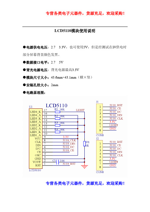

OSC:振荡器当使用芯片内置振荡器时,引脚必须接到VDD(芯片内置振荡器提供显示系统的时钟信号。
)。
使用外部振荡器时则连接到此引脚。
如果OSC 引脚连接到VSS,则禁止内部振荡器及外部振荡器,显示不计时并停留在直流状态。
为避免这种情况,在停止时钟之前使芯片进入关闭模式。
(!!!由原理图可知,OSC接VDD,故默认使用内置振荡器) 振荡器驱动时钟发生器产生驱动内部电路的多种信号。
内部芯片操作不影响数据总线上的操作。
D/C: 模式选择输入:选择命令/地址或输入数据SCE: 芯片使能使能引脚充许输入数据,低电平有效。
RES:复位此信号会复位设备,应用于初始化芯片。
低电平有效。
功能描述地址计数器 (AC)地址计数器为写入显示数据存储器指定地址。
X地址 X6~X0和Y地址Y2~Y0 分别设置。
写入操作之后,地址计数器依照V标志自动加1。
显示状态(所有点开/关和正常/反转映象)通过‘显示控制’命令的E、D位来设置。
寻址列通过地址指针寻址,地址范围为:X:0~83(1010011),Y :0~5(101)。
地址不充许超出这个范围。
在垂直寻址模式(V=1),Y地址在每个字节之后递增.经最后的Y地址(Y=5)之后,Y绕回0,X递增到下一列的地址。
在水平寻址模式(V=0),X地址在每个字节之后递增(见图6),经最后的X地址(X=83)之后,X绕回0,Y递增到下一行的地址。
经每一个最后地址之后(X=83,Y=5),地址指针绕回地址(X=0,Y=0)。
温度补偿由于液晶体的温度依赖,在低温时必须增加LCD控制电压VLCD来维持对比度。
图7展示高速率的VLCD。
在 PCD8544,VLCD的温度系数可以通过设置TC1和TC0位来选择四个值(见表2)。
(例程中选择V LCD温度系数2,即TC1 and TC0为10)串行接口时序指令&数据指令格式分为两种模式:如果D/C(模式选择)置为低,当前字节解释为命令字节。
如果D/C置为高,接下来的字节将存储到显示数据RAM。

MSP430单片机与液晶显示器的串行接口方案设计(一) 1概述点阵式液晶与外部的硬件接口简单,能以点阵或图形方式显示出各种信息,因此在电子设计中得到广泛应用。
但是,对它的接口设计必须遵循一定的硬件和时序规范,不同的液晶显示驱动器,可能需要采用不同的接口方式和控制指令才能够实现所需信息的显示。
某些液晶显示驱动器与外部的接口必须采用串行方式,而其串行接口往往不是标准的串行接口,这就为这类液晶显示驱动器的设计带来了困难。
针对上述问题,本文提出一种利用微控制器(MCU)的I/O端口,通过软件设计模拟与所使用的液晶显示驱动器规范相符的串行总线的设计思想,实现MCU对液晶显示驱动器的控制,从而建立起一套不但可以显示各种字符,而且可以动态显示曲线的游人显示系统。
2系统设计本文所建立的液晶显示系统,选用美国德州仪器(TI)公司的MSP430F149微控制器来控制液晶显示驱动器uPD16682A,从而实现各种信息的显示。
2.1MSP430F14X微控制器简介TI公司的MSP430F14X微控制器与其它MSP430系列微控制器相同,均甚至一个真正的正交16位RISCCPU内核:具有16个可单周期全寻址的16位寄存器,仅27条的精简指令集以及7种均采用双重取数据技术(DDFT)的一致性寻址方式。
DDFT技术利用每个时钟脉冲对存储器进行两次数据存取操作。
从而不再需要复杂的时钟乘法和指令流水线方案。
MSP430F14X系列MCU片内不但包括60多KB的Flash、2KB的RAM、一个看门狗时钟、12位16通道的A/D转换器、定时器、高精度比较器、PWM以及高速的USART控制器等常用资源,还在某些型号中集成了LCD控制器。
其I/O资源丰富,且每个输入/输出(I/O)引脚上都提供了矢量中断功能,每个外围器件都支持复杂的事件驱动型操作。
同其它微控制器相,带片内Flash的微控制器可将系统功耗降低5倍,并且减小了硬件线路板空间,与现代程序设计技术(如计算分支以及高级语言(如C语言)结合使用,使得MSP430的体系结构更为高效。
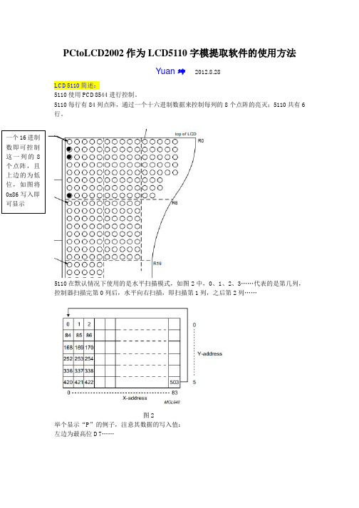
PCtoLCD2002作为LCD5110字模提取软件的使用方法Yuan 坤2012.8.28LCD5110简述:5110使用PCD8544进行控制。
5110每行有84列点阵,通过一个十六进制数据来控制每列的8个点阵的亮灭;5110共有6行。
5110在默认情况下使用的是水平扫描模式,如图2中,0、1、2、3……代表的是第几列,控制器扫描完第0列后,水平向右扫描,即扫描第1列,之后第2列……图2举个显示“P ”的例子,注意其数据的写入值:左边为最高位D7……图3由图3可以看出,要显示“P ”,首先写入0x1f ,则第一列显示一个竖杠,之后控制器自动水平右移到下一列,再写入0x05,则出现两个小横杆,这个两个横杆就是0x05中00000101中两个1所处的位置,写完第二列后,控制器自动跳到第三列,再写入0x07,第四列写入0x00后,P 就显示出来了。
端显示一个小点,你也得控制写入一个8位的二进制数置设置好,即写入0x01。
即你不能一次性控制一个点阵,只能一介绍部分,这些部分设置之后是不用再改的:图4图6由图5和图6总结软件的设置:1.主界面中的“字宽”与“字高”的设置才是真正对显示到液晶屏上的字体的大小的设置。
2.对话框中“点阵”的值会对字模的编码产生影响。
因为5110是从第一列水平向右写入数据,取模时也是从左往右的那样的取,所以就拿一个16*16的汉字来讲,将汉字的上半截16列数据,可以分成很多份,而点阵=字宽/份数即16*16的汉字,字宽为16,若将其分为两份,则每份存8列的数据若将其分为一份,则每份存16列的数据例“元”字宽16字高16:点阵=8{0xDF,0xDF,0xDD,0xDD,0xDD,0x1D,0xDD,0xDD },{0xDD,0x1D,0xDD,0xDD,0xDD,0xDF,0xDF,0xFF },{0x7F,0xBF,0xDF,0xEF,0xF3,0xFC,0xFF,0xFF },{0xFF,0xC0,0xBF,0xBF,0xBF,0xBF,0x87,0xFF }点阵=16{0xDF,0xDF,0xDD,0xDD,0xDD,0x1D,0xDD,0xDD,0xDD,0x1D,0xDD,0xDD,0xDD,0xDF,0xDF,0xFF },{0x7F,0xBF,0xDF,0xEF,0xF3,0xFC,0xFF,0xFF,0xFF,0xC0,0xBF,0xBF,0xBF,0xBF,0x87,0xFF },可以出,点阵8和点阵16的数据是完全一样的,只不过就是这个二维数组中的每个一维的数据位数不同罢了。
#include"stdafx.h" #include"font.h"
//************************************************* //函数名称:LCDWriteByte( //函数功能:写字节数据 //函数入口:dat 数据;command :1为写数据 0为写指令 //函数出口:无
//************************************************* void
LCDWriteByte(uchar dat, uchar command { uchar i; CLRB(LCD_PORT,LCD_CS; if (command SETB(LCD_PORT,LCD_DC; else CLRB(LCD_PORT,LCD_DC; for(i = 0;i < 8;i++ { if(dat & 0x80 SETB(LCD_PORT,LCD_DIN; else
CLRB(LCD_PORT,LCD_DIN; CLRB(LCD_PORT,LCD_CLK; dat = dat << 1;
SETB(LCD_PORT,LCD_CLK; } SETB(LCD_PORT,LCD_CS; }
//************************************************* //函数名称:LCDSetAddr( //函数功能:写地址 //函数入口:X:行;Y:列 //函数出口:无
//************************************************* void LCDSetAddr(uchar X, uchar Y { LCDWriteByte(0x40 | Y, 0; // column LCDWriteByte(0x80 | X, 0; // row } //************************************************* //函数名称:LCDWriteChar( //函数功能:写字符 //函数入口:asc 字符 //函数出口:无
//************************************************* void
LCDWriteChar(uchar asc { uchar line; asc = asc-32; for (line=0; line<6; line++ LCDWriteByte(font[asc][line], 1;//从ACSII码表中读取字节,然后写入液晶 }
//************************************************* //函数名称:LCDwriteNum( //函数功能:写数字 //函数入口:地址坐标:X,Y;数字:num; 数字位数:size //函数出口:无 //************************************************* void LCDWriteNum(uchar X,uchar Y,uint num,uchar size { uchar i; uchar n[5]={0};
n[0]= num%10; n[1]=(num/10%10; n[2]=(num/100%10; n[3]=(num/1000%10;
n[4]=(num/10000%10; LCDSetAddr(X,Y; //光标定位 for(i = size;i > 0;i-- LCDWriteChar(n[i-1]+'0'; //从ACSII码表中读取字节,然后写入液晶 }
//************************************************* //函数名称:LCDWriteString( //函数功能:写字符串 //函数入口:地址坐标X,Y 字符串起始指
针*s //函数出口:无 //************************************************* void LCDWriteString(uchar X,uchar Y,char *s { LCDSetAddr(X,Y; //光标定位 while (*s LCDWriteChar(*s++; }
//************************************************* //函数名称:LCDClear( //函数功能:LCD清屏 //函数入口:无 //函数出口:无
//************************************************* void LCDClear( { uint i,j; LCDWriteByte(0x0c, 0; LCDWriteByte(0x80, 0; for (i=0; i < 84; i++ for(j = 0;j < 6;j++ LCDWriteByte(0x00, 1; } //************************************************
* //函数名称:LCDInit( //函数功能:LCD初始化 //函数入口:无 //函数出口:无 //************************************************* void
LCDInit( { CLRB(LCD_PORT,LCD_RST; SETB(LCD_PORT,LCD_RST;
CLRB(LCD_PORT,LCD_CS; SETB(LCD_PORT,LCD_CS; LCDWriteByte(0x21, 0; // 使用扩展命令设置LCD模式 LCDWriteByte(0xc8, 0; // 设置偏置电压LCDWriteByte(0x06, 0; // 温度校正 LCDWriteByte(0x13, 0; // 1:48
LCDWriteByte(0x20, 0; // 使用基本命令 LCDClear(; // 清屏 LCDWriteByte(0x0c, 0; // 设定显示模式,正常显示 CLRB(LCD_PORT,LCD_CS; // 关闭LCD }
//************************************************* //函数名称:Display( //函数功能:显示 //函数入口:无 //函数出口:无
//************************************************* void
Display( { LCDClear(; LCDWriteString(0,0," hello world "; LCDWriteString(0,5," MADE BY LJF "; }。