XN1048
- 格式:pdf
- 大小:175.64 KB
- 文档页数:8



第七节 扩散问题的偏微分方程模型物质的扩散问题,在石油开采、环境污染、疾病流行、化学反应、新闻传播、煤矿瓦斯爆炸、农田墒情、水利工程、生态问题、房屋基建、神经传导、药物在人体内分布以及超导、液晶、燃烧等诸多自然科学与工程技术领域,十分普遍地存在着. 显然,对这些问题的研究是十分必要的,其中的数学含量极大. 事实上,凡与反应扩散有关的现象,大都能由线性或非线性抛物型偏微分方程作为数学模型来定量或定性地加以解决.MCM的试题来自实际,是“真问题⊕数学建模⊕计算机处理”的“三合一”准科研性质的一种竞赛,对上述这种有普遍意义和数学含量高,必须用计算机处理才能得到数值解的扩散问题,当然成为试题的重要来源,例如,AMCM-90A,就是这类试题;AMCM-90A要研究治疗帕金森症的多巴胺(dopamine )在人脑中的分布,此药液注射后在脑子里经历的是扩散衰减过程,可以由线性抛物型方程这一数学模型来刻划. AMCM-90A要研究单层住宅混凝土地板中的温度变化,也属扩散(热传导)问题,其数学模型与AMCM-90A一样,也是线性抛物型方程.本文交代扩散问题建模的思路以及如何推导出相应的抛物型方程,如何利用积分变换求解、如何确定方程与解的表达式中的参数等关键数学过程,且以AMCM-90A题为例,显示一个较细致的分析、建模、求解过程.§1 抛物型方程的导出设(,,,)u x y z t 是t 时刻点(,,)x y z 处一种物质的浓度. 任取一个闭曲面S ,它所围的区域是Ω,由于扩散,从t 到t t +∆时刻这段时间内,通过S 流入Ω的质量为2221(cos cos cos )dSd t ttSu u uM a b c t x y zαβγ+∆∂∂∂=++∂∂∂⎰⎰⎰. 由高斯公式得2222221222()d d d d t ttu u u M a b c x y z t x y z +∆Ω∂∂∂=++∂∂∂⎰⎰⎰⎰. (1) 其中,222,,a b c 分别是沿,,x y z 方向的扩散系数. 由于衰减(例如吸收、代谢等),Ω内的质量减少为22d d d d t ttM k u x y z t +∆Ω=⎰⎰⎰⎰,(2) 其中2k 是衰减系数.由物质不灭定律,在Ω内由于扩散与衰减的合作用,积存于Ω内的质量为12M M -.换一种角度看,Ω内由于深度之变化引起的质量增加为3[(,,,)(,,,)]d d d d d d d . (3)t ttM u x y z t t u x y z t x y zux y z t t Ω+∆Ω=+∆-∂=∂⎰⎰⎰⎰⎰⎰⎰显然312M M M =-,即2222222222d d d d ()d d d d .t ttt ttux y z t t u u u a b c k u x y z t x y z+∆Ω+∆Ω∂∂∂∂∂=++-∂∂∂⎰⎰⎰⎰⎰⎰⎰⎰由,,t t ∆Ω之任意性得2222222222u u u u a b c k u t x y z∂∂∂∂=++-∂∂∂∂ (4) 方程(4)是常系数线性抛物型方程,它就是有衰减的扩散过程的数学模型,对于具体问题,尚需与相应的定解条件(初始条件与边界条件等)匹配才能求得确定情况下的解.§2 Dirac 函数物理学家Dirac 为了物理模型之需要,硬是引入了一个当时颇遭微词的,使得数学与物理学传统密切关系出现裂痕的“怪”函数:0,0,() ()1.,0,x x x dx x δδ+∞-∞≠⎧==⎨∞=⎩⎰ (5)它的背景是清晰的,以一条无穷长的杆子为例,沿杆建立了一维坐标系,点的坐标为x ,杆的线密度是()x ρ,在(,]x -∞段,杆子质量为()m x ,则有d ()(), ()d ().d x m x x x x m x xρρ-∞==⎰. (6)设此无穷长的杆子总质量为1,质量集中在0x x =点,则应有001,,()0,,x x m x x x >⎧=⎨<⎩ 或写成 0()()m x H x x =-, 其中()H x 为1,0,()0,0,x H x x >⎧=⎨<⎩ 如果沿用(6)中的算法,则在质量集中分布的这种情形有00,,(),0.x x x x ρ≠⎧=⎨∞=⎩且0()d ()xx x H x x ρ-∞=-⎰,于是得()d 1.x x ρ+∞-∞=⎰. (7)但是,从传统数学观点看,若一个函数除某点处处为零,则不论哪种意义下的积分,都必定为零,(7)式岂能成立!但是,δ函数对于物理学而言是如此之有用,以致物理学家正当地拒绝放弃它. 尽管当时数学家们大都嘲笑这种函数,但P.A.M.Dirac 及其追随者们在物理领域却收获颇丰,Dirac 于1933年获诺贝尔物理奖. 当然Dirac 也意识到()x δ不是一个通常的函数,至于找一种什么办法来阐明()x δ这一符号的合法性,那就是数学家的任务了. 1940年,法国数学家许瓦兹(L.Schwartz )严格证明了应用()x δ的正确性,把δ函数置于坚实的数学基础上;1950年,L. Schwartz 获数学界最高奖Fields 奖.δ函数的重要性质有:1)0()d 1x x x δ+∞-∞-=⎰. (8) 2)00()()d ()x x f x x f x δ+∞-∞-=⎰. (9)其中()(,)f x C ∈-∞+∞,即0()x x δ-摘出了()f x 在0x x =的值.3)00()()dH x x x x dxδ-=-. (10)4)()x δ的导数是存在的,不过要到积分号下去理解:00()()(),x x f x dx f x δ+∞-∞''-=-⎰ (11) ()()00()()(1)().n n n x x f x dx f x δ+∞-∞-=-⎰(12)事实上,由于0()x x δ-在,+∞-∞处为零,则形式地用分部积分公式000()()()()d ()()d ,x x f x x x f x xx x f x x δδδ+∞+∞-∞-∞+∞-∞'---'=-⎰⎰其中,()(,)n f x C ∈-∞+∞,于是有(11)与(12)公式.5)对于()(,)x C ϕ∈-∞+∞,有000()()()()x x x x x x ϕδϕδ-=-. (13)6)1()() (0)||bx x b b δδ=≠. (14) 7)000000(,,)()()()x x y y z z x x y y z z δδδδ---=---. (15)8)付立叶变换00[()].i x y y e λδ--=F (16) [()] 1.x δ=F (17)11221122[()()][()][()].C x x C x x C x x C x x δδδδ-+-=-+-F F F (18) 9)拉普拉斯变换00[(),[() 1.x x x e x δδδ--==F F (19) 11221122[()]()][()[()].C x x C x x C x x C x x δδδδ-+-=-+-F F F (20)从上面的定义与性质看出,Delta 函数()x δ与一般可微函数还是有重大区别的,我们说它是“广义函数. ”§3 Cauchy 问题的解设扩散源在点000(,,)x y z 处,则此扩散问题满足Cauchy 问题2222222222000, (21)(,,,0)()()(). (22)u u u u a b c k u tx y z u x y z M x x y y z z δδδ⎧∂∂∂∂=++-⎪∂∂∂∂⎨⎪=---⎩对(21)(22)进行付立叶变换,且令123ˆ(,,), (,)[(,,,)]ut u x y z t λλλλλ==F , 由于222222123222ˆˆˆ[], [], [],u u u uu u x y zλλλ∂∂∂=-=-=-∂∂∂F F F 102030000()[(,,,0)][()][()][()] ,i x y z u x y z M x x y y z z Me λλλδδδ-++=---=F F F F 故得常微分方程Cauchy 问题1020302222222123()ˆ()0,ˆ(0,).i x y z du a b c k udtu Meλλλλλλλ-++⎧++++=⎪⎨⎪=⎩ 得唯一解2222222123102030()()ˆ(,)a b c k t i x y z ut Me λλλλλλλ-+++-++=. (23)对(23)求逆变换1-F,由于212214[]a xa e λ---=F ,211021240[]()i x e aa ex x λλ----=-F , 故得12222000222ˆ(,,,)[]()()()exp 444u x y z t ux x y y z z k t a t b t c t -=⎧⎫---=----⎨⎬⎩⎭F2222000222()()().444x x y y z z k t a t b t c t ⎧⎫---=----⎨⎬⎩⎭(24) 如果认为经过了相当长时间后,扩散已经终止,物质分布处于平衡状态,则方程(4)中的0ut∂=∂,于是有线性椭圆型方程的边值问题 22222222220, (,,)(,,)(,,).D u u u a b c k u x y z D xy z u x y z x y z ϕ∂⎧∂∂∂++-=∈⎪∂∂∂⎨⎪=⎩也可以用付立叶变换求解. 当然,根据实际情况,还可以考虑第二边条件(,,)Dux y z n ∂∂=ψ∂或第三边条件[](,,)D uu x y z nαβρ∂∂+=∂等,其中D ∂是区域D 的边界,n 是外法线方向,,αβ是实常数.§4 参数估计在Cauchy 问题(21)(22)的解(23)中,有四个未知的参数,,,a b c k ,它们分别是扩散与衰减过程中的扩散系数与衰减系数的算术平方根. 至于点源的质量与位置000,(,,)M x y z 是已知的.设观测取样为:11112222(,,,), (,,,),,(,,,),n n n n x y z m x y z m x y z m 取样时刻为1t =(不然设00, t t t τ=是取样时间,则(21)变成2200t xx yy U t a U t b U =++ 2200zz t c U t k U -,对τ而言,取样时间为1,而方程形状与(21)一致),把在(,,)i i i x y z 点观测到的物质密度i m 与公式(24)都取对数,令1t =,则2222000222()()()ln (,,,1)ln []444x x y y z z u x y z abc k a b c ---=--+++. (25) 令222000222()()()111,,,,,,444x x y y z z X Y Z a b c αβγ---====-=-=-2ln abc k ε=--,则(25)写成 ln (,,,1)W u x y z X Y Z αβγε==+++, (26)而我们已观测得(,,,)1,2,,i i i i X Y Z W i n = 的数据,用三元回归分析方法求出,,,αβγε的估计值如下:ˆˆˆˆ()W X Y Z εαβγ=-++, (27) 其中11111111, , , ,n n n nk i i i k k k k W W X X Y Y Z Z n n n n ========∑∑∑∑ˆˆˆ,,αβγ满足方程组 111213102122232031323330ˆˆˆ,,ˆˆˆ,,ˆˆˆ,.l l l l l l l l l l l l αβγαβγαβγ⎧++=⎪⎪++=⎨⎪++=⎪⎩ 其中10201130122211223311112131123211()(), ()(),()(),(), (), (),()(), ()(),()(), n nk k k k k k nk k k nn nk k k k k k nnk k k k k k nk k k l W X W W l Y Y W W l Z Z W W l X X l Y Y l Z Z l X X Y Y l X X Z Z l Y Y Z Z l ==========--=--=--=-=-=-=--=--=--∑∑∑∑∑∑∑∑∑1231133223, , .l l l l l ===由ˆˆˆ,,αβγ可求得222,,a b c 的估计值,即222111ˆˆˆ, , ˆa b cαβγ=-=-=-. 又由于 2ln k abc ε=+-, (28) 由(27)式可得ˆε,再把ˆˆˆ,,a b c 代入(28)得 2ˆˆˆˆˆln kabc ε=+-. (29)至此得到参数2222,,,a b c k 的估计值2222ˆˆˆˆ,,,a b c k ,把它们代入(24)分别替代2222,,,a b c k ,则得不含未知参数的解(,,,)u x y z t 的近似表达式.§5 竞赛试题分析AMCM-90A 不可用本文的思路与方法加以解决;该试题由东华盛顿大学数学系Yves Nievergelt 提供,要求研究药物在脑中的分布,题文称:“研究脑功能失调的人员欲测试新的药物的效果,例如治疗帕金森症往脑部注射多巴胺(Dopamine )的效果,为了精确估计药物影响到的脑部区域,它们必须估计注射后药物在脑内空间分布区域的大小和形状.“研究数据包括50个圆柱体组织样本的每个样本药物含量的测定值(如图6-1),每个圆柱体长0.76mm ,直径0.66mm ,这些互相平行的圆柱体样本的中心位于网格距为1m m ×0.76×m m ×1mm 的格点上,所以圆柱体互相间在底面上接触,侧面互不接触. 注射是在最高计数的那个圆柱体的中心附近进行的. 自然在圆柱体之间以及由圆柱体样本的覆盖的区域外也有药物.“试估计受到药物影响的区域中药物的分布. ”“一个单位表示一个闪烁微粒的计数,或多巴胺的4.753×10⁻¹⁸克分子量,例如表6-1指出位于后排当中那个圆柱体的含药量是28353个单位. ”后方垂直截面164442 1320 414 188 480 7022 14411 5158 352 2091 23027 28353 13138 681 789 21260 20921 11731 727 213 130337651715453前方垂直截面163 324 432 243166 712 1055 6098 1048 232 2137 15531 19742 4785 330 444 11431 14960 3182 301 29420611036 258188图6-1数学模型只是实际问题的近似,要建立数学模型,一般首先要对所研究的实际问题进行必要和允许的简化与假设,而且,不同的简化与假设,又可能导致不同的数学模型,例如[2]是抛物型方程模型,而[3]则是椭圆方程模型.假设:(1)注射前大脑中的多巴胺含量可以忽略不计.(2)大脑中多巴胺注射液经历着扩散与衰减的过程,且沿,,x y z 三个方向的扩散系数分别是常数,衰减使质量之减少与深度成正比.(3)注射点在后排中央那个圆柱中心,即注射点的坐标000(,,)x y z 已知,注射量有医疗记录可查,是已知的.(4)注射瞬间完成,可视为点源delta 函数. (5)取样也是瞬间完成,取样时间已知为1t =.(6)样本区域与整个大脑相比可以忽略,样本组织远离脑之边界,不受大脑边界面的影响.在以上假设之下,显然可以用本文前面讲过的思路来建模,于是得AMCM-90A 的数学模型为Cauchy 问题(21)(22),解的表达式为(24),且用三元回归分析来估出参数,,,a b c k ,于是可以求得任意位置任意时刻药物的深度.如果所给数据认为是在平衡状态测得的,药物注射进脑后,从高深度处向低深度处扩散,与扩散同时,一部分药物进入脑细胞被吸收固定,扩散系数与吸收系数都是常数,但过一段时间,所有药物都被脑细胞所固定,达到了平衡态. 在这种假设下,[3]给出了下述的分析、建模、求解过程.设(,,,)v x y z t 是t 时刻在(,,)x y z 点处游离的药物浓度,(,,,)w x y z t 是t 时刻(,,)x y z 点处吸收固定的药物浓度,(,,)u x y z 是达到平衡态时(,,)x y z 点处吸收固定的药物浓度. 又设游离药物在各方向上有相同的扩散系数k ,吸收系数为h ,于是有vk v hv t∂=∆-∂. (30) 又whv t∂=∂,即吸收速度与游离的浓度成正比,代入(30)得 ()v k w w t h t t∂∂∂=∆-∂∂∂. (31) 对(31)关于t 从0到+∞积分得t t t k vw wh+∞+∞+∞====∆-. (32)由于最后无游离药物,故(,,,)0v x y z +∞=,又开始时(0)t =无被吸收的药物,故(,,,0)0, (,,,0)0w x y z w x y z =∆=;平衡状态在t =+∞时达到,这时(,,)u x y z =(,,,)w x y z +∞,于是由(32)得(,,,0)ku u v x y z h-∆+=, (33) 其中(,,,0)v x y z 是开始时的浓度分布,近似于注射点的点源脉冲函数. 把此注射点取为坐标原点(0,0,0),则(,,,0)(,,),v x y z L x y z L δ=是注射量,于是2k h σ⎛⎫= ⎪⎝⎭记2(,,)u u L x y z σδ-∆+=, (34)作付立叶变换得22222222ˆˆ(),ˆ,1()s u u L Lus σξησξη+++==+++ 再作反变换得u σ-=-, (35)其中C 是可计算常数.如果考虑各向不同性,设,,x y z 方向上扩散系数分别为222,,a b c ,注射点在000(,,)x y z ,则 222222000222()()()u u u a b c u L x x y y z z x y z δδδ⎛⎫∂∂∂-+++=--- ⎪∂∂∂⎝⎭, 于是解为(,,)u x y z =exp 1⎧⎪⎨⎪⎩ ,(36)(36)中的D 可计算常数.用前面类似的方法可以进行参数估计.在建模过程中,点源函数的使用显然与实况有差别;尤其是认为扩散系数与吸收系数都是常数,对于人脑这种有复杂结构的区域,这种假设与实际不会完全符合;夜间与白天(睡与醒)对这些系数有无影响?脑中各点这些系数是否有变?除时间位置应考虑外,可能还与药液浓度有关. 如此看来,脑内药液分布的数学模型很可能不是常系数线性偏微分方程,而是函数系数的线性微分方程甚至是非线性偏微分方程. 这时,其解不再能用封闭公式来表达,求解过程会变得极为复杂,所以也可以考虑是否试用其他数学模型来解,例如在平衡态的假设下,用回归分析方法建立药液的模拟分布(,,)u f x y z =.对一个实际问题,其数学模型未必唯一,各模型间孰优孰劣,没有一般的判别法,须经实践来检验.参 考 文 献[1]叶其孝,大学生数学建模竞赛辅导教材,湖南教育出版社,1993.[2]Christopher, R. Malone, Gian Pauletto, James, I. Zoellick, Distribution of Dopamine in the Brain, The Journal of Under graduate Mathematics, and its Applications, vol. 12(1991), Special Issue: The 1991 Mathematical Contest in Modeling, pp. 211-223.[3]孙晓东,荆秦,梁俊,脑中药物分布的数学模型,数学的实践与认识,1991年No. 4,63-69. [4]中国科学院数理统计组,常用数理统计方法,科学出版社,19784.。
Sysmex XN Series and SP-10 MaintenanceDocument Number: RHEAHS14010MUL Revision Number: 2.50 Document Type: Procedure Effective Date: 6/17/2022 2:26:04 PM Location: 3. APL Folder Structure\Hematology HE\CBC and Differential\Sysmex XN - 59\Edmonton ZoneRHEAHS14010MUL Sysmex XN Series and SP-10 MaintenanceAPPLICABILITYThis document is applicable to APL staff at the following Edmonton Zone sites: GNH,RAH, SGH and UAH.PURPOSEThis procedure describes how to perform the daily clean, shutdown, startup and maintenance (daily, weekly and monthly) of the Sysmex XN series and SP-10 analyzers.MATERIALSPROCEDURE4.1. XN Series MaintenanceAll maintenance procedures must be signed off on the Sysmex XN Series Maintenance form.4.1.1. Daily4.1.2. Weekly4.1.3. Monthly4.1.4. Every Six Months4.1.5. Yearly or As Needed4.2. SP-10 Maintenance (RAH and UAH only)All maintenance procedures should be signed off on the Sysmex SP-10 Maintenance form.4.2.1. DailyWhen in shutdown, remove the trap chamber from the right side of4.2.2.Weekly4.2.3.As NeededREFERENCES1. Sysmex XN-1000 / XN-2000 Automated Hematology Analyzers CLSI Procedure, Document number:1004-LSS. Rev. 1, March 20132. XN Series (For XN-1000 system) Instructions for Use (North American Edition), November 2012.3. SP-10 Instructions for use.4. XN-9000 Instructions for use.RELATED DOCUMENTSRHEAHF14010MULA Sysmex XN Series MaintenanceRHEAHS14006MUL Sysmex XN Series - Performing QCRHEAHS14019MUL Sysmex XN Series - Manual Shutdown and StartupRHERHS00004MUL Inter-Instrument Variability for Hematology Coagulation and Special Coagulation AnalyzersRHERHF00002MUL Hematology Inter-Instrument Variability Excel WorksheetRQMPCS14000MUL Annual Autovalidation CheckRHEAHF14010MULB Sysmex SP-10 MaintenanceHE24-097 Evaluating Quality Control using the Beyond Care Quality Monitoring BCQM System。

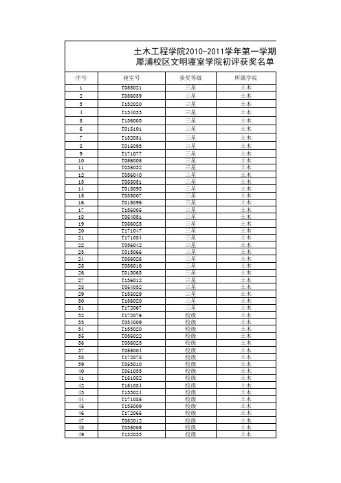
负责老师:唐锐时间:2011.3.3
学院总寝室数:612个
本次评选出:1、三星级文明寝室612×5%≈31个
2、校级文明寝室612×20%≈122个
3、院级文明寝室612×30%≈184个
共计337个
其中T036021本应被评选为三星级文明寝室,因被检查出违章电器,被取消资格。
T036041本应被评选为院级文明寝室,因被检查出违章电器,被取消资格。
本次评选出:1、三星级文明寝室612×5%≈31个
2、校级文明寝室612×20%≈122个
3、院级文明寝室612×30%≈184个
共计337个
本应被评选为三星级文明寝室,因被检查出违章电器,被取消资格。
应被评选为院级文明寝室,因被检查出违章电器,被取消资格。
竹纤维素纳米晶须的结构与性质张会;邵秋娟;何建新;崔世忠【摘要】利用酸水解制备竹纤维纳米晶须(CNW),借助原子力显微镜(AFM)和核磁共振,研究了酸水解不同时间对制备的竹纤维纳米晶须形貌和结构的影响。
结果表明:硫酸水解15min之前NCW的形貌呈棒状结构,超过15min转变为较细的针状结构;在酸水解时问为20min时长径比最大,结晶度最高,次晶含量最低,晶粒尺寸最大。
通过偏光显微镜观察CNW悬乳液,其具有形成手性向列相液晶指纹状结构的性质。
CNW质量分数为1%时,浓度太低晶须之间不能相互作用,当cNw质量分数达到2.5%(2.5%~7.5%),随着CNW悬乳液浓度增加,形成的手性向列相液晶的指纹间距减小。
%Cellulose nanowhiskers (CNW) were prepared by sulfuric acid hydrolysis from bamboo fibers. With atomic force microscope (AFM) and NMR. The effects of sulfuric acid hydrolysis times on morphological behavior and structure of the nanowhiskers were investigated. Results showed that the morphology of cellulose nanowhiskers were long rod-like before sulfuric acid hydrolysis 15 min, more than 15 min change to the morphology were fine needle structure; Samples hydrolyzed for 20 min had the largest aspect ratio, the highest crystallinity, the least paracrystal and the largest crystallite dimension. Observing the CNW solution by polarizing microscope, it can form an anisotropic chiral nematic liquid crystal phase. Concentration is 1%, bamboo CNW concentration is too low induce whisker cannot interaction between, When concentration 2.5% (2.5%-7.5%), along with the CNWconcentration increases, the domain size of the chiral nematic phase decrease.【期刊名称】《纤维素科学与技术》【年(卷),期】2012(020)003【总页数】7页(P27-33)【关键词】竹浆纤维;纳米晶须;液晶【作者】张会;邵秋娟;何建新;崔世忠【作者单位】中原工学院纺织学院,河南郑州450007;河南平棉纺织集团有限公司,河南平顶山467000;中原工学院纺织学院,河南郑州450007;中原工学院纺织学院,河南郑州450007【正文语种】中文【中图分类】TS102.2纤维素是自然界中最丰富的具有生物降解性的高分子材料。

AN1048Application noteST7 software LCD driverIntroductionThis note describes a technique for driving Liquid Crystal Displays (LCD) with any standardST7 Microcontroller (MCU) i.e without any specific on-chip LCD driver hardware. Thistechnique offers a solution for applications which require a display at low cost together withthe versatile capabilities of the standard ST7 MCUs. This note also provides a technique tocontrol the LCD contrast through software.After an introduction on LCDs in Section1, Section2 & 3 of this note describes the typicalwaveforms required to drive an LCD with a multiplexing rate of 1 or 2 (duplex) and 4(quadruplex). Section3 presents a solution based on a standard ST7 MCU directly driving aquadruplex LCD. This solution can be implemented with any ST7 MCU as it only requiresthe standard I/O ports and one timer, both of which are standard features on all ST7 MCUs.Section4 describes how to control the contrast through software. Finally, Section5 gives abrief overview of the LCD demo board including the board schematics. The demo board,based on a ST72F321B microcontroller, allows the user to develop and test applicationsusing an LCD device.The program size (~300 bytes), the CPU load required for controlling the LCD (0.2%), andthe number of external components is kept to the minimum (two external resistors per COMline). The number of I/O’s is the same as a solution using an on-chip LCD hardware driver oran external hardware LCD driver. With software contrast control, it is a very flexible solutionthat can be adapted easily to a range of applications.May 2006 Rev 51/21Contents AN1048Contents1LCD requirements . . . . . . . . . . . . . . . . . . . . . . . . . . . . . . . . . . . . . . . . . . . 32LCD drive signals . . . . . . . . . . . . . . . . . . . . . . . . . . . . . . . . . . . . . . . . . . . 42.1Single backplane LCD drive . . . . . . . . . . . . . . . . . . . . . . . . . . . . . . . . . . . . 42.2Duplexed LCD drive . . . . . . . . . . . . . . . . . . . . . . . . . . . . . . . . . . . . . . . . . . 42.3Quadruplex LCD drive . . . . . . . . . . . . . . . . . . . . . . . . . . . . . . . . . . . . . . . . 62.3.1LCD mean voltage calculation . . . . . . . . . . . . . . . . . . . . . . . . . . . . . . . . . 82.3.2Contrast calculation . . . . . . . . . . . . . . . . . . . . . . . . . . . . . . . . . . . . . . . . . 9 3Example of a quadruplex LCD with ST72F321B . . . . . . . . . . . . . . . . . . 114Software contrast control . . . . . . . . . . . . . . . . . . . . . . . . . . . . . . . . . . . . 164.1Contrast calculations . . . . . . . . . . . . . . . . . . . . . . . . . . . . . . . . . . . . . . . . 165LCD demo board . . . . . . . . . . . . . . . . . . . . . . . . . . . . . . . . . . . . . . . . . . . 185.1Schematic . . . . . . . . . . . . . . . . . . . . . . . . . . . . . . . . . . . . . . . . . . . . . . . . . 185.2Power supply . . . . . . . . . . . . . . . . . . . . . . . . . . . . . . . . . . . . . . . . . . . . . . 195.3Programming . . . . . . . . . . . . . . . . . . . . . . . . . . . . . . . . . . . . . . . . . . . . . . 195.4Reset . . . . . . . . . . . . . . . . . . . . . . . . . . . . . . . . . . . . . . . . . . . . . . . . . . . . 195.5Oscillation system . . . . . . . . . . . . . . . . . . . . . . . . . . . . . . . . . . . . . . . . . . 19 6Revision history . . . . . . . . . . . . . . . . . . . . . . . . . . . . . . . . . . . . . . . . . . . 202/21AN1048LCD requirements 3/211 L CD requirements With a low Root Mean Square (RMS i.e.:) voltage applied to it, an LCD ispractically transparent. The LCD segment is inactive(OFF) if the RMS voltage is below theLCD threshold voltage and is active(ON) if the LCD RMS voltage is above the thresholdvoltage. The LCD threshold voltage depends on the quality of the liquid used in the LCD andthe temperature. The optical contrast is defined by the difference in transparency of a LCDsegment ON (dark) and a LCD segment OFF (transparent). The optical contrast depends onthe difference between the RMS voltage on an ON segment (V ON ) and the RMS voltage onan OFF segment (V OFF ). The higher the difference between V ON (rms) and V OFF (rms), thehigher the optical contrast. The optical contrast also depends on the level of V ON versus theLCD threshold voltage. If V ON is below or close to the threshold voltage, the LCD iscompletely or almost transparent. If V OFF is close or above the threshold voltage, the LCD iscompletely dark.In this document, contrast is defined as D = V ON (rms) / V OFF (rms).The applied LCD voltage must alternate to give a zero DC value in order to ensure a longLCD life time.The higher the multiplexing rates, the lower the contrast. The signal period has also to beshort enough to avoid visible flickering on the display.The LCD voltage for each segment is equal to the difference between the S and COMvoltages (see Figure 1).Figure 1.Equivalent Electrical Schematic of an LCD Segment Note:The DC Value should never be more than 100mV (refer to the LCD manufacturer’sdatasheet). Otherwise the life time can be shortened. The frequency range is 30 - 200Hztypically. If it is less, it flickers; if it is more, the power consumption increases.Mean Signal 2()CRsSCOMLCD drive signals AN10484/212 L CD drive signals2.1 Single backplane LCD driveIn a single backplane drive, each LCD segment is connected to a segment line(Sx) and toone backplane(common line) common to all the segments. A display using S segments isdriven with S+1 MCU output lines. The backplane is driven with a “COM” signal controlledbetween 0 and V DD with a duty cycle of 50%.When switching a segment “ON”, a signal with opposite polarity to “COM” is sent to thecorresponding “Segment” pin. When the non-inverted signal “COM” is sent to the “Segment”pin, the segment is “OFF”. Using an MCU, the I/O operates in output mode either at logic 0or 1.Figure 2.LCD signals for direct drive2.2 Duplexed L CD driveIn a duplexed drive, two backplanes are used instead of one. Each LCD segment line(Sx) isconnected to two LCD segments, each one connected on the other side to one of the twobackplanes or common lines(refer to Figure 3). Thus, only (S/2)+2 MCU pins are necessaryto drive an LCD with S segments.Three different voltage levels have to be generated on the backplanes: 0, V DD /2 and V DD . The“Segment” voltage levels are 0 and V DD only. Figure 4 shows typical Backplane, Segmentand LCD waveforms. The intermediate voltage V DD /2 is only required for the Backplanevoltages. The ST7 I/O pins selected as “Backplanes” are set by software to output mode forAN1048LCD drive signals5/210 or V DD levels and to high impedance input mode for V DD /2. When one backplane is active,the other one is neutralised by applying V DD /2 to it. This V DD /2 voltage is defined by tworesistors of equal value, externally connected to the I/O pin. By using an MCU with flexibleI/O pin configuration, a duplexed LCD drive can be implemented with only 2 externalresistors bridge (each on two com lines).Figure 3.Basic LCD Segment Connection in duplexed modeFigure 4.LCD signals for duplexed mode (used in the ST7 example)COM1COM2S1S11S12S2S3LCD drive signals AN10486/212.3 Quadruplex LCD driveIn a quadruplex LCD drive, four backplanes are used. Each LCD pin is connected to fourLCD segments, with each segment connected on the other side to one of the fourbackplanes. Thus, only (S/4)+4 MCU pins are necessary to drive an LCD with S segments.For example: to drive an LCD with 128 segments (32 x4), only 36 I/O ports are required (32I/O ports to drive the segments, 4 I/O ports to drive the backplanes).Three different voltage levels have to be generated on the common lines: 0, V DD /2, V DD .The Segment line voltage levels are 0 and V DD only. The LCD segment is inactive if theRMS voltage is below the LCD threshold voltage and is active if the LCD RMS voltage isabove the threshold. Figure 6 shows typical Backplane, Segment and LCD waveforms. Theintermediate voltage V DD /2 is only required for Backplane voltages. The MCU I/O pinsselected as “Backplanes” are set by software to output mode for 0 or V DD levels and to thehigh impedence input mode for V DD /2. The V DD /2 voltage is defined by two resistors ofequal value, externally connected to the I/O pins. When one backplane or COM is active, theother ones are neutralized by applying V DD /2 to them.Figure 5.Basic LCD Segment Connection in Quadruplexed Mode COM1COM2S1S11S12S2S3COM3COM4S13S14AN1048LCD drive signals7/21LCD drive signals AN10488/212.3.1 LCD mean voltage calculationThe LCD mean voltage must be very close to zero to guarantee long life to the LCD. The LCD meanvoltage for ON and OFF periods can be calculated as:Vmean(ON) = 1/8 Vseg + 1/8 (-Vcom) + 3(Vseg - Vr/2) + 3(-Vr/2) ----(1)Vmean(Off) = 3(Vseg/2) + 3(-Vr/2) -----(2)Vmean(ON) and Vmean(Off) assume identical periods for each phase.From eqn (1) & (2), to get Vmean(ON) and Vmean(Off) = zeroVseg = Vcom = Vr = VccWhere:Vcom = Max voltage on COM lineVr/2 = Voltage in the middle of the resistor bridge applied on the COM lineVseg = Max voltage on Segx lineVcc = Microcontroller power supplyAN1048LCD drive signals9/212.3.2 Contrast calculationThe performance of an LCD driving system is defined by the contrast:Contrast(D) = Vrms(ON) / Vrms(Off)For the quadruplex signal as described on the previous page:Contrast(D) = Vrms(ON) / Vrms(OFF) = 0.661Vcc / 0.43Vcc = 1.52Vrms ON ()1T---f t ()2t d 0T ∫=Vrms ON ()1T---Vcc ()2t d 0T 8---∫Vcc ()2t d T 8---2T 8------∫Vcc 2----------⎝⎠⎛⎞2t d 2T 8------T∫++=Vrms ON ()1T ---Vcc ()2T 8---Vcc ()2T 8---Vcc ()24------------------6T ()8⁄⋅+⋅+⋅⎝⎠⎜⎟⎛⎞=Vrms ON ()716------Vcc ()2=Vrms ON ()0.661Vcc=Vrms OFF ()1T---0()t d 0T 8---∫0()t d T 8---2T 8------∫Vcc 2----------⎝⎠⎛⎞2t d 2T 8------T ∫++=Vrms OFF ()316------Vcc ()2=Vrms OFF ()0.43Vcc=LCD drive signals AN104810/21For comparison, a hardware LCD drive uses 1/3 bias voltage. With 1/3 bias control, the contrast value (D) is 1.73. Therefore, 1/3 bias gives only a small advantage of contrast versus temperature. This advantage is reduced to zero when using software contrast control.3 Example of a quadruplex LCD with ST72F321BThe following example describes a drive for a quadruplex mode (4COM) LCD using theST72F321B (TQFP64 pin package 10 x 10). Refer to Figure8. The only externalcomponents needed for driving the LCD are eight resistors. The resistor value of 56K isused to reduce the DC voltage on the LCD(~7.5 mV). This value can be further decreasedto get the better DC voltage on the LCD but this will result in an increase of the currentconsumption. One I/O port per segment and one I/O port for each COM line are needed todrive the LCD. For example: T o drive a quadruplex LCD that has 128 segments (with 32segment lines and 4 COM lines) requires only a total of 36 I/O ports.In the example program, the Port PA0-A5, PB0-B7, PD0-D7, PF7-F0, PE7-E6pins areconnected to the 32 segment lines and are used to generate the segment signals. PortsPC3...PC0 are connected to the 4 COM lines and used to generate the COM signals. TheLCD driver consists of two initialization routines (port init, timer init) and a TimerA interruptroutine “timer_rt”. To activate the LCD, these two initialization routines have to be called.After these routines are called, the ST7 gets the timer Output Compare 1 & Output Compare2 interrupts.11/21The LCD Timing is generated by the TimerA output compare interrupt. Each cycle consistsof four phases, one for each backplane. Each COM line generates its waveform during thecorresponding phase e.g. COM1 line during phase1. During other phases it remains at levelV DD/2. Each phase consists of two parts:1. Active time2. Dead timeDuring the Active time, the segment lines and COM lines are used to drive the LCD. Duringdead time Segment and COM lines are used to tune the contrast.12/21Active time starts after the Output Compare 1 interrupt and dead time starts after the Output Compare 2 interrupt. A total of 16 interrupts are generated in each frame period with four interrupts per control period. There are 2 Output Compare 1 events (OC1_1 and OC1_2) and 2 Output Compare 2 events in each phase.These are explained as follows:During OC1_1, V DD is applied to the segments which have to be turned ON and 0 for the segments which have to be turned OFF. The COM line which corresponds to this phase is set to low level. Other COM lines are set to level V DD/2.During OC2, all segments and COM lines are inactive (set to low level) if we want to decrease the Vrms (see Figure9) and COM lines are set low, segments are set high if we want to increase the Vrms (see Figure10).During OC1_2, Segment Lines are supplied with voltage levels which are inverted to the one applied during OC1_ line which corresponds to this phase is set to high level.Other COM lines are set to level V DD/2.Again during OC2, all segments and COM lines are inactive(set to low level) if we want to decrease the Vrms and COM lines are set high, segments are set low if we want to increase the Vrms (see Figure10).13/2114/2115/214 Software contrast controlThe software contrast control is under pending patent from STMicroelectronics. The use ofthis technique with a non-STMicroelectronics' Microcontroller has to be agreed bySTMicroelectronics.The LCD contrast is controlled entirely by software without the use of any externalcomponents. LCD contrast can be adjusted to the optimal value depending on the operatingvoltage of the LCD used. The LCD contrast is controlled by varying the timing of dead phaseas shown in the LCD timing diagram.Deadtime can be used to decrease as well as to increase the Vrms of the LCD. Deadtime isthe voltage compensation time to regulate rms voltage up and down. Dead time can beimplemented either after each control period or at the end of the frame. T o avoid flickering,the duration of the dead time must be adjusted depending on the quality of LCD and thefrequency of the frame.In the example in Figure9, the Rms value of the LCD decreases if the duration of dead timeis increased and Rms value increases if the duration of dead time decreases. In Figure10,this works the opposite way.4.1 ContrastcalculationsLet the frame period = T + xTwhere T - Active Time, xT- Dead Timex- Proportion of dead time, Vx - Voltage during the dead timeVrms ON()1T xT+----------------f t()2t dT XT+()∫=Vrms ON()1T xT+----------------Vcc()2t Vcc–()2t Vcc()2⁄()2t Vx2()t8⋅dxT8------∫+d2T8------T∫+dT8---2T8------∫+dT8---∫⎝⎠⎜⎟⎜⎟⎜⎟⎛⎞=Vrms ON()1T xT+----------------Vcc()2T8---Vcc()2T8---Vcc()24------------------2T8------Vx2xT8------⋅⎝⎠⎛⎞8⋅+⋅+⋅+⋅⎝⎠⎜⎟⎛⎞=16/2117/21Since Vx = 0 (incase of a decrease in Vrms)Since Vx = 0 (incase of a decrease in Vrms)Where Dx = Contrast calculation with contrast control methodVrms ON ()11x +------------14Vcc 2()32-------------------------Vx ()2x ⋅+⎝⎠⎜⎟⎛⎞=Vrms ON ()11x +------------14Vcc 2()32-------------------------=Vrms ON ()11x+------------0.661Vcc =Vrms OFF ()1T xT +----------------0()t 0()t Vcc ()2⁄()2t Vx 2()t 8⋅d 0xT 8------∫+d 2T 8------T∫+d T 8---2T 8------∫+d 0T 8---∫⎝⎠⎜⎟⎜⎟⎛⎞=Vrms OFF ()11x +------------6Vcc 2()32----------------------Vx 2x ⋅+⎝⎠⎜⎟⎛⎞=Vrms OFF ()11x+------------0.18Vcc =Contrast Dx ()11x+------------0.661Vcc ⎝⎠⎛⎞11x+------------0.18Vcc ⎝⎠⎛⎞------------------------------------------------=LCD demo board AN104818/21The contrast D, between V ON and V OFF is constant (quality of contrast). We only change the optical contrast by tuning V ON close to the threshold value of the LCD.5 LCD demo board 5.1 SchematicAN1048LCD demo board19/215.2 Power supplyThe LCD demo board should be supplied by a maximum DC voltage of 5V . The board isprovided with the connector JP1 for this board supply.Note:For the demo software loaded inside the micro, the board should be supplied with 5V. The software attached to this application note displays the word “EMBEDDED” and tunesautomatically its contrast from transparent to dark with the ST software pattented method. The Vrms increase is performed by putting the segment voltage once at Vdd, once at -Vdd during the dead times, the Vrms decrease is performed by putting at 0 the segment voltage during the same dead times. The voltage average is then kept. Refer to the software attached to this application note for more details.5.3 ProgrammingThe demo board uses the ST72F321B microcontroller and can be programmed using the ICC protocol. The board is provided with the ICC connnector JP2. By default, OSC_TYP is programmed as a resonator oscillator in the option bytes. Y ou can disable the option bytes when you want to use the ICC clock to program the micro.5.4 ResetThe device can be reset by pressing the switch s1 on the demo board.5.5 Oscillation systemThe demo board is mounted with a 16 MHz crystal with 8 MHz fcpu. Y ou can change thisclock value but need to modify the timer setting inside the software accordingly.Revision history AN104820/216 Revision historyTable 1.Document revision historyDateRevisionChanges09-May-20065Document reformattedReferences to ST72F321 changed to ST72F321BFormulae for VRMS(ON) and VRMS(OFF) corrected, Section 4.1 on page 16Note updated, Section 5.2 on page 19AN1048Please Read Carefully:Information in this document is provided solely in connection with ST products. STMicroelectronics NV and its subsidiaries (“ST”) reserve the right to make changes, corrections, modifications or improvements, to this document, and the products and services described herein at any time, without notice.All ST products are sold pursuant to ST’s terms and conditions of sale.Purchasers are solely responsible for the choice, selection and use of the ST products and services described herein, and ST assumes no liability whatsoever relating to the choice, selection or use of the ST products and services described herein.No license, express or implied, by estoppel or otherwise, to any intellectual property rights is granted under this document. If any part of this document refers to any third party products or services it shall not be deemed a license grant by ST for the use of such third party products or services, or any intellectual property contained therein or considered as a warranty covering the use in any manner whatsoever of such third party products or services or any intellectual property contained therein.UNL ESS OTHERWISE SET FORTH IN ST’S TERMS AND CONDITIONS OF SAL E ST DISCL AIMS ANY EXPRESS OR IMPL IED WARRANTY WITH RESPECT TO THE USE AND/OR SAL E OF ST PRODUCTS INCL UDING WITHOUT L IMITATION IMPL IED WARRANTIES OF MERCHANTABILITY, FITNESS FOR A PARTICULAR PURPOSE (AND THEIR EQUIVALENTS UNDER THE LAWS OF ANY JURISDICTION), OR INFRINGEMENT OF ANY PATENT, COPYRIGHT OR OTHER INTELLECTUAL PROPERTY RIGHT. UNLESS EXPRESSLY APPROVED IN WRITING BY AN AUTHORIZE REPRESENTATIVE OF ST, ST PRODUCTS ARE NOT DESIGNED, AUTHORIZED OR WARRANTED FOR USE IN MILITARY, AIR CRAFT, SPACE, LIFE SAVING, OR LIFE SUSTAINING APPLICATIONS, NOR IN PRODUCTS OR SYSTEMS, WHERE FAIL URE OR MAL FUNCTION MAY RESUL T IN PERSONAL INJURY, DEATH, OR SEVERE PROPERTY OR ENVIRONMENTAL DAMAGE.Resale of ST products with provisions different from the statements and/or technical features set forth in this document shall immediately void any warranty granted by ST for the ST product or service described herein and shall not create or extend in any manner whatsoever, any liability of ST.ST and the ST logo are trademarks or registered trademarks of ST in various countries.Information in this document supersedes and replaces all information previously supplied.The ST logo is a registered trademark of STMicroelectronics. All other names are the property of their respective owners.© 2006 STMicroelectronics - All rights reservedSTMicroelectronics group of companiesAustralia - Belgium - Brazil - Canada - China - Czech Republic - Finland - France - Germany - Hong Kong - India - Israel - Italy - Japan - Malaysia - Malta - Morocco - Singapore - Spain - Sweden - Switzerland - United Kingdom - United States of America21/21。

一种新颖的差分混合蛙跳算法王娜;高学军【摘要】在使用智能优化算法处理函数优化问题时,保持种群的多样性及加快种群的收敛速度可以提升一个算法的性能.针对混合蛙跳算法在寻优过程中易陷入局部最优和早熟收敛的缺点,本文提出了一种新颖的差分混合蛙跳算法.该算法借鉴差分进化中的变异交叉思想,在前期利用子群中其他个体的有用信息来更新最差个体,增加局部扰动性,以提高种群的多样性;在后期为加快收敛速度使用最好个体的信息进行变异交叉操作.同时本文使用归档集进一步保留种群的多样性.仿真测试结果表明:该算法在求解优化问题时较基本蛙跳算法和平均值蛙跳算法具有更好的寻优性能.【期刊名称】《计算机系统应用》【年(卷),期】2017(026)001【总页数】5页(P196-200)【关键词】智能优化;混合蛙跳算法;差分进化;归档集【作者】王娜;高学军【作者单位】广东工业大学应用数学学院,广州510006;广东工业大学应用数学学院,广州510006【正文语种】中文混合蛙跳算法(SFLA)[1]是由Eusuff等人于2003年提出的一种模拟青蛙觅食过程的新的智能优化算法. 该算法融合了模因演算算法(memetic algorithm, MA)和粒子群优化算法(particle swarm optimization, PSO)两者的优点, 具有模型简单、易于实现、控制参数少等优点, 近年来已被成功应用于智能优化领域[2-5]. 但相关实验测试表明, SFLA虽具有局部精确搜索的特点, 却因在寻优过程只利用了全局最优和子群最优青蛙对子群最差青蛙更新使得算法前期容易陷入局部最优, 导致种群多样性降低, 求解精度低, 后期收敛速度慢. 为了提高SFLA解决优化问题的性能, 国内外学者对其进行了大量的研究. 如: Elbeltagi等人[6]将“认知分量”引入子群内部搜索策略中, 提高了算法的求解成功率, 一定程度上提高了算法的全局搜索能力; 赵芳等人[7]根据适应值所在范围定义新的粒子分类标准避免了算法的盲目搜索, 通过动态调整惯性权重提高全局搜索能力, 并借用柯西变异算子跳出局部最优的陷阱, 从而提高了算法的优化性能; 张强等人[8]通过动态改变多样性比例来改变子群最优值的多样性密度来增加种群多样性.本文在借鉴前人研究成果的基础之上, 针对SFLA[9]易陷入局部最优和收敛速度慢的缺点, 根据差分进化算法中的变异、交叉操作不仅能充分利用种群信息从而提高算法的多样性, 同时还可以有效地提高算法的搜索速度的特点, 提出了一种新的更新策略, 在算法前期加入改进的差分算子rand-1来更新个体, 增加随机扰动性, 提高全局搜索能力; 在算法后期, 加入差分算子best-rand-2来提高算法的收敛速度. 同时, 处理越界个体时对变化尺度进行动态调整, 改进了算法的寻优精度. 而在每一代更新完成后, 引入归档集, 保存了好的被替代个体, 而被替代的这些个体可能包含有用的信息, 有助于收敛到最优点, 从而保持了种群的多样性. 仿真实验测试结果表明, 改进后的差分蛙跳算法(记为DSFLA)较基本SFLA和基于平均值改进算法(记为SFLA-AV)而言, 新算法加快了收敛速度, 大大提高了求解精度, 说明了算法的有效性和可行性.2 混合蛙跳算法在已知定义空间中随机产生N个点组成初始化群体X={X1,X2,...,XN}, 第i点的位置代表函数在可行域的一个解Xi=(xi1,xi2,..., xid), 其中d=1,2,...,r, r为解空间的维数. 根据目标函数计算出所有青蛙的初始适应值并升序排序, 第一只青蛙记为种群的最优青蛙Xg=(xg1,xg2,..., xgd). 然后, 把种群平均分为s个子群, 每个子群有p 只青蛙, N=p×s, 划分原则为式中, i=1,2,...,s, j=1,2,...,p. 每个子群分别用Xb=(xb1,xb2,..., xbd)、Xw=(xw1,xw2,..., xwd)来表示适应值最好的青蛙和适应值最差的青蛙. 在子群的每一次进化中, 对最差的青蛙Xw的位置进行调整, 其更新策略为:青蛙移动的步长:(1)青蛙更新后的位置:(2)其中, 是之间的随机数, 是青蛙允许移动的最大距离.对子群最差青蛙Xw位置更新过程中, 如果更新策略产生一个较好的解, 则用新解Xw’更新Xw; 否则用种群最优的青蛙Xg替换子群最优青蛙Xb执行公式(1)(2); 若仍没有改进, 则从定义空间中随机产生一个新解取代Xw, 这样就完成了子群的一次进化. 所有子群按照这种更新策略更新最差个体, 直到子群迭代次数. 然后各子群的所有个体重新混合, 计算适应值按升序排序后重新分组, 继续进行局部搜索更新, 如此反复直到达到全局最大迭代次数或者满足约束条件, 算法停止.3 改进的差分混合蛙跳算法3.1 引进差分算子更新策略差分进化算法(differential evolution, DE)[10]是一类基于群体智能的启发式随机搜索算法. DE类似于遗传算法, 存在变异、交叉和选择等多种进化模式[11], 为提高种群的多样性和算法的收敛速度, 本文在算法进化前期和后期分别借鉴了rand-1和best-rand-2两种模式并进行了改进, 使得该算法比基本SFLA具有更好的寻优性能.在算法前期, 为保持种群的多样性, 提高全局的搜索能力, 不是对子群中的最差个体更新, 而是随机选取三个个体, 其中一个个体作为目标个体, 其他两个个体用来更新移动步长, 借鉴差分变异操作[12]的思想, 引入改进的差分算子rand-1, 新的更新策略为:, (3)式子中, , , 为子群中随机选取的三个个体, Xw为产生的新个体, .在算法后期, 为加快算法的收敛速度, 有助于收敛到最优点, 用子群中最好的个体作为目标个体, 随机选取两个个体更新移动步长, 引入差分算子best-rand-2, 新的更新策略为:(4)式子中, , 为子群中随机选取的两个个个体, Xw为产生的新个体, Xb为子群最优个体.引入改进的差分变异操作后, 为了进一步提高算法的局部搜索能力, 继续保持种群的多样性, 对产生的新个体Xw继续执行交叉操作[12], 改进后的交叉更新策略如下: (5)式子中, 为当前个体第j维的值, 其中, w=1,2,...,N; j=1,2,...,d. 同时, 每次都对新产生的个体进行改进的越界处理, 处理策略如下:(6)式子中, Xwj为当前个体第j维的值, 其中, w=1,2,...,N; j=1,2,...,d; Ubj、Lbj分别指定义空间第j维的上下界; CurT指当前种群进化代数, MaxT指种群进化最大代数.3.2 归档集在子群进化的过程中, 有些被更新掉的个体可能包含有用的信息, 有助于算法收敛到最优点, 因此在子群进化中加入归档集[13]可以保存被更新的最差个体. 归档集的具体操作: 在初始化的时候, 随机产生2N个个体, 建立归档集. 在每一个种群进化中, 每个子群更新次数内淘汰的个体中的一半随机取代归档集里相同数目的个体.归档集的使用进一步保持了种群的多样性, 提高算法的全局搜索能力.3.3 算法流程改进的差分混合蛙跳算法具体的流程如下所示.第一步: 设置相关参数种群规模N=200, 解空间维数VecterSize=5, 子群数S=20, 子群内更新次数TeamIter=10, 种群最大迭代次数为MaxIter=100, F=0.4, P=0.5; 第二步: 随机初始化种群的每只青蛙, 并根据目标函数计算每只青蛙的适应值;第三步: 根据青蛙适应值对种群升序排序, 记录第一只青蛙为种群的最优青蛙Fbest; 第四步: 将种群按指定规则划分为20个子群, 每个子群10只青蛙, 并记录每个子群中最优的青蛙和最差的青蛙;第五步: 建立归档集, 随机产生两倍种群数量的青蛙, 并计算每只青蛙的适应值;第六步: 按以下规则对每个子群独立进化10次, 每一次子群进化完成后产生20个被淘汰的个体, 按适应值降序排序, 将前10个随机取代归档集中的10个个体.在种群迭代30%代以前, 根据差分算子rand-1按式子(3)更新得到新个体, 对新个体按式子(5)越界处理, 如果新个体的适应值优于子群最差个体则替代之并按式子(4)进行交叉操作, 再次越界处理; 否则从归档集随机选取三个个体按式子(3)进行更新得到新个体, 越界处理计算适应值, 如果新个体的适应值优于子群最差个体则用新个体替代子群最差个体, 否则从归档集中随机选一个替代之;在种群迭代30%代以后, 根据差分算子best-rand-2按式子(4)更新并按式子(6)越界处理得到新个体, 如果新个体的适应值优于子群最差个体则替代之并按式子(5)进行交叉操作并越界处理; 否则从归档集随机选取两个个体和子群最优个体按式子(4)更新产生新个体并越界处理计算适应值, 如果新个体的适应值优于子群最差个体则用新个体替代子群最差个体, 否则从归档集中随机选一个替代之;第七步: 是否达到子群最大迭代次数, 是则完成一次种群迭代, 并将进行第八步, 否则返回第六步;第八步: 混合子群中所有的青蛙, 重新形成一个完整的种群, 并按适应值升序排序, 记录第一只青蛙为种群的最优青蛙Fbest, 完成种群的一次更新, 判断是否满足终止条件, 是则输出最优青蛙Fbest的相关信息, 算法结束; 否则进行种群下一代更新, 跳转第四步.4 实验结果及分析4.1 测试函数与条件为了验证DSFLA的优化性能, 本文选取五个典型的连续优化函数进行测试, 并与基本混合蛙跳算法(SFLA)和基于平均值改进算法(记为SFLA-AV)作比较.为了验证DSFLA的优化性能, 本文选取五个典型的连续优化函数进行测试, 并与基本混合蛙跳算法(SFLA)和基于平均值改进算法[14](记为SFLA-AV)作比较.其中f1:Sphere Model是单峰函数、f2:Rastr-igin Function、f3:Schaffer1 Function、f4:Griewand Function和f5:Ackley Function都是复杂的多峰函数, 它们的理论最优值均为0. 算法的参数设置为: 种群规模N=200, 解空间维数VecterSize=5, 子群数S=20, 子群内更新次数TeamIter=10, 种群最大迭代次数为MaxIter=100, F=0.4, P=0.5. 为减小偶然性对算法测试结果产生的影响, 每个算法均独立运行30次后取平均值, 仿真结果如表1所示.表1 计算结果函数算法平均最优解最优解目标精度成功率(%) f1SFLASFLA-AVDSFLA4.65945e-052.70181e-084.34131e-565.3853e-091.5790e-262.6591e-631×10-5300100 f2SFLASFLA-AVDSFLA1.299362.97235e-0300.0018001×10-360397 f3SFLASFLA-AVDSFLA7.77887e-012.79900e-017.77515e-130.18890.02073.3829e-151×10-1000100 f4SFLASFLA-AVDSFLA1.1815e-032.4235e-0502.0214e-07001×10-1803100 f5 SFLASFLA-AVDSFLA3.5555e-016.3219e-022.4277e-150.00742.6550e-108.8818e-161×10-14001004.2 实验结果和分析从表1的求解结果对比看出: DSFLA的最优解、平均值和求解精度及成功率都明显优于基本的SFLA和SFLA-AV, 说明DSFLA算法后期能进行更加精确的局部搜索, 具有更好的稳定性. 就平均最优解求解的精度来说, 在f1, f2, f3, f4, f5函数中, DSFLA比SFLA分别提高了1×1051倍, 1×10∞倍, 1×10¹²倍, 1×10∞倍,1×1014倍; DSFLA比SFLA-AV分别提高了1×1048倍, 1×10∞倍, 1×10¹²倍, 1×10∞倍, 1×10¹³倍, 说明DSFLA的求解精度得到有效的提高. 其中, 对于函数f2, f4, DSFLA均搜索出理论最优解.图1 的进化曲线图1~5为3种算法分别对5个典型的连续优化函数搜索最优解的进化曲线. 从图中可以得到: SFLA和SFLA-AV在算法早期就陷入局部最优的陷阱, 后期的收敛速度很慢, 几乎跳不出局部最优的陷阱, 而DSFLA在算法进化前期能很好的保持种群的多样性, 提高全部的搜索能力, 在算法进化的后期, DSFLA的收敛速度加快, 具有能寻得高质量的最优解的能力.从表格数据和图像的进化曲线都能表明DSFLA无论是在求最优解的稳定性上还是质量上都能明显胜于SFLA和SFLA-AV, 证明了本文改进的算法是有效和可行的优化算法.5 总结SFLA是一种新的智能寻优算法. 本文借鉴差分变异的思想, 利用子群个体间的信息共享, 改进子群最差个体的更新策略, 不仅有效的提高了算法的全局寻优能力和求解精度, 还加快了算法的收敛速度. 算法还通过加入归档集及动态调整越界个体的变化尺度来进一步保持算法的多样性, 提高了优化性能. 实验仿真结果表明DSFLA 的有效性和稳定性.1 Eusuff MM, Lansey KE. Optimization of water distribution network design using the shuffled frog leaping algorithm. Journal of Water Resources Planning and Management, 2003, 129(3): 210–225.2 郭业才,张苗青.基于混合蛙跳算法的多模盲均衡算法.兵工学报,2015,36(7):1280–1287.3 王茜,张粒子,舒隽,王楠.基于阈值选择策略的改进混合蛙跳算法在电网规划中的应用.电力系统保护与控制,2011, 39(3):35–39.4 刘紫燕,唐思腾,冯丽,帅暘.混合蛙跳在AF协作通信功率优化中的应用.计算机仿真,2015,32(7):190–310.5 陈海涛,沈强.改进的蛙跳算法在云计算资源中的研究.计算机与数字工程,2015,(8):1382–1506.6 Elbeltagi E, Hegazy T, Grierson D. A modified shuffled frog-leapingoptimization algorithm applications to project management. Structure and Infrastructure Engineering, 2007, 3(1): 53–60.7 赵芳,张桂珠.基于新搜索策略的混合蛙跳算法.计算机应用与软件,2015,(8):224–228.8 张强,刘丽杰,郭昊.一种保持种群多样性的改进混洗蛙跳算法.计算机与数字工程,2015,(7):1175–1211.9 Liong SY, Atiquzzaman M. Optimal design of water distribution network using shuffled complex evolution. The Institution of Engineers, 2004, 44(1): 93–107.10 Rahnamayan S, Tizhoosh HR, Salama MMA. Opposition based dufferential evolution. IEEE Trans. on Evolutionary Computation, 2008,12(1): 64–79.11 贺毅朝,王熙照,刘坤起,王彦祺.差分演化的收敛性分析与算法改进.软件学报,2010,21(5):875–885.12 熊伟丽,陈敏芳,王肖,徐保国.运用改进差分进化算法辨识Hammerstein模型.南京理工大学学报,2013,37(4):536– 542.13 王丽,刘玉树,徐远清.基于在线归档技术的多目标粒子群算法.北京理工大学学报,2006,26(10):883–887.14 赵鹏军,刘三阳.求解复杂函数优化问题的混合蛙跳算法.计算机应用研究,2009,26(7):2435–2437.Novel Differential Shuffled Frog Leaping AlgorithmWANG Na, GAO Xue-Jun(Department of Applied mathematics, Guangdong University of Technology, Guangzhou 510520, China)Abstract:When using optimization algorithms to solve optimization problems, keeping the diversity of population and accelerating the convergence rate of the population can improve the performance of an algorithm. To overcome the main drawbacks of the shuffled frog leaping algorithm which may be easy to get stuck and premature convergence in a local optimal solution, this paper proposes a novel differential shuffled frog leaping algorithm. The algorithm is based on the idea of mutation crossover in differential evolution. In the earlier, it uses beneficial information of the other individuals in sub-group to update the worst individual, which increases the local disturbance and the diversity of population; in the later, the algorithm uses the best individual information to conduct the mutation and cross operation for speeding up the convergence rate of the population. Moreover, this paper uses the archive to keep the diversity of population. The experimental results show that the proposed algorithm is superior to the basic frog leaping algorithm and the average frog leaping algorithm in solving optimization problems.Key words:optimization algorithm; shuffled leaping frog algorithm; differential evolution; archive①基金项目:广东省科技计划(2013B051000075)收稿时间:2016-04-22;收到修改稿时间:2016-06-12[doi:10.15888/ki.csa.005563]在已知定义空间中随机产生N个点组成初始化群体X={X1,X2,...,XN}, 第i点的位置代表函数在可行域的一个解Xi=(xi1,xi2,..., xid), 其中d=1,2,...,r, r为解空间的维数. 根据目标函数计算出所有青蛙的初始适应值并升序排序, 第一只青蛙记为种群的最优青蛙Xg=(xg1,xg2,..., xgd). 然后, 把种群平均分为s个子群, 每个子群有p 只青蛙, N=p×s, 划分原则为式中, i=1,2,...,s, j=1,2,...,p. 每个子群分别用Xb=(xb1,xb2,..., xbd)、Xw=(xw1,xw2,..., xwd)来表示适应值最好的青蛙和适应值最差的青蛙. 在子群的每一次进化中, 对最差的青蛙Xw的位置进行调整, 其更新策略为:青蛙移动的步长:青蛙更新后的位置:其中, 是之间的随机数, 是青蛙允许移动的最大距离.对子群最差青蛙Xw位置更新过程中, 如果更新策略产生一个较好的解, 则用新解Xw’更新Xw; 否则用种群最优的青蛙Xg替换子群最优青蛙Xb执行公式(1)(2); 若仍没有改进, 则从定义空间中随机产生一个新解取代Xw, 这样就完成了子群的一次进化. 所有子群按照这种更新策略更新最差个体, 直到子群迭代次数. 然后各子群的所有个体重新混合, 计算适应值按升序排序后重新分组, 继续进行局部搜索更新, 如此反复直到达到全局最大迭代次数或者满足约束条件, 算法停止.3.1 引进差分算子更新策略差分进化算法(differential evolution, DE)[10]是一类基于群体智能的启发式随机搜索算法. DE类似于遗传算法, 存在变异、交叉和选择等多种进化模式[11], 为提高种群的多样性和算法的收敛速度, 本文在算法进化前期和后期分别借鉴了rand-1和best-rand-2两种模式并进行了改进, 使得该算法比基本SFLA具有更好的寻优性能.在算法前期, 为保持种群的多样性, 提高全局的搜索能力, 不是对子群中的最差个体更新, 而是随机选取三个个体, 其中一个个体作为目标个体, 其他两个个体用来更新移动步长, 借鉴差分变异操作[12]的思想, 引入改进的差分算子rand-1, 新的更新策略为:式子中, , , 为子群中随机选取的三个个体, Xw为产生的新个体, .在算法后期, 为加快算法的收敛速度, 有助于收敛到最优点, 用子群中最好的个体作为目标个体, 随机选取两个个体更新移动步长, 引入差分算子best-rand-2, 新的更新策略为:式子中, , 为子群中随机选取的两个个个体, Xw为产生的新个体, Xb为子群最优个体.引入改进的差分变异操作后, 为了进一步提高算法的局部搜索能力, 继续保持种群的多样性, 对产生的新个体Xw继续执行交叉操作[12], 改进后的交叉更新策略如下: 式子中, 为当前个体第j维的值, 其中, w=1,2,...,N; j=1,2,...,d. 同时, 每次都对新产生的个体进行改进的越界处理, 处理策略如下:式子中, Xwj为当前个体第j维的值, 其中, w=1,2,...,N; j=1,2,...,d; Ubj、Lbj分别指定义空间第j维的上下界; CurT指当前种群进化代数, MaxT指种群进化最大代数.3.2 归档集在子群进化的过程中, 有些被更新掉的个体可能包含有用的信息, 有助于算法收敛到最优点, 因此在子群进化中加入归档集[13]可以保存被更新的最差个体. 归档集的具体操作: 在初始化的时候, 随机产生2N个个体, 建立归档集. 在每一个种群进化中, 每个子群更新次数内淘汰的个体中的一半随机取代归档集里相同数目的个体.归档集的使用进一步保持了种群的多样性, 提高算法的全局搜索能力.3.3 算法流程改进的差分混合蛙跳算法具体的流程如下所示.第一步: 设置相关参数种群规模N=200, 解空间维数VecterSize=5, 子群数S=20, 子群内更新次数TeamIter=10, 种群最大迭代次数为MaxIter=100, F=0.4, P=0.5; 第二步: 随机初始化种群的每只青蛙, 并根据目标函数计算每只青蛙的适应值;第三步: 根据青蛙适应值对种群升序排序, 记录第一只青蛙为种群的最优青蛙Fbest; 第四步: 将种群按指定规则划分为20个子群, 每个子群10只青蛙, 并记录每个子群中最优的青蛙和最差的青蛙;第五步: 建立归档集, 随机产生两倍种群数量的青蛙, 并计算每只青蛙的适应值;第六步: 按以下规则对每个子群独立进化10次, 每一次子群进化完成后产生20个被淘汰的个体, 按适应值降序排序, 将前10个随机取代归档集中的10个个体.在种群迭代30%代以前, 根据差分算子rand-1按式子(3)更新得到新个体, 对新个体按式子(5)越界处理, 如果新个体的适应值优于子群最差个体则替代之并按式子(4)进行交叉操作, 再次越界处理; 否则从归档集随机选取三个个体按式子(3)进行更新得到新个体, 越界处理计算适应值, 如果新个体的适应值优于子群最差个体则用新个体替代子群最差个体, 否则从归档集中随机选一个替代之;在种群迭代30%代以后, 根据差分算子best-rand-2按式子(4)更新并按式子(6)越界处理得到新个体, 如果新个体的适应值优于子群最差个体则替代之并按式子(5)进行交叉操作并越界处理; 否则从归档集随机选取两个个体和子群最优个体按式子(4)更新产生新个体并越界处理计算适应值, 如果新个体的适应值优于子群最差个体则用新个体替代子群最差个体, 否则从归档集中随机选一个替代之;第七步: 是否达到子群最大迭代次数, 是则完成一次种群迭代, 并将进行第八步, 否则返回第六步;第八步: 混合子群中所有的青蛙, 重新形成一个完整的种群, 并按适应值升序排序,记录第一只青蛙为种群的最优青蛙Fbest, 完成种群的一次更新, 判断是否满足终止条件, 是则输出最优青蛙Fbest的相关信息, 算法结束; 否则进行种群下一代更新,跳转第四步.4 实验结果及分析4.1 测试函数与条件为了验证DSFLA的优化性能, 本文选取五个典型的连续优化函数进行测试, 并与基本混合蛙跳算法(SFLA)和基于平均值改进算法(记为SFLA-AV)作比较.为了验证DSFLA的优化性能, 本文选取五个典型的连续优化函数进行测试, 并与基本混合蛙跳算法(SFLA)和基于平均值改进算法[14](记为SFLA-AV)作比较.其中f1:Sphere Model是单峰函数、f2:Rastr-igin Function、f3:Schaffer1 Function、f4:Griewand Function和f5:Ackley Function都是复杂的多峰函数, 它们的理论最优值均为0. 算法的参数设置为: 种群规模N=200, 解空间维数VecterSize=5, 子群数S=20, 子群内更新次数TeamIter=10, 种群最大迭代次数为MaxIter=100, F=0.4, P=0.5. 为减小偶然性对算法测试结果产生的影响, 每个算法均独立运行30次后取平均值, 仿真结果如表1所示.表1 计算结果函数算法平均最优解最优解目标精度成功率(%) f1SFLASFLA-AVDSFLA4.65945e-052.70181e-084.34131e-565.3853e-091.5790e-262.6591e-631×10-5300100 f2SFLASFLA-AVDSFLA1.299362.97235e-0300.0018001×10-360397 f3SFLASFLA-AVDSFLA7.77887e-012.79900e-017.77515e-130.18890.02073.3829e-151×10-1000100 f4SFLASFLA-AVDSFLA1.1815e-032.4235e-0502.0214e-07001×10-1803100 f5 SFLASFLA-AVDSFLA3.5555e-016.3219e-022.4277e-150.00742.6550e-108.8818e-161×10-14001004.2 实验结果和分析从表1的求解结果对比看出: DSFLA的最优解、平均值和求解精度及成功率都明显优于基本的SFLA和SFLA-AV, 说明DSFLA算法后期能进行更加精确的局部搜索, 具有更好的稳定性. 就平均最优解求解的精度来说, 在f1, f2, f3, f4, f5函数中, DSFLA比SFLA分别提高了1×1051倍, 1×10∞倍, 1×10¹²倍, 1×10∞倍,1×1014倍; DSFLA比SFLA-AV分别提高了1×1048倍, 1×10∞倍, 1×10¹²倍, 1×10∞倍, 1×10¹³倍, 说明DSFLA的求解精度得到有效的提高. 其中, 对于函数f2, f4, DSFLA均搜索出理论最优解.图1 的进化曲线图1~5为3种算法分别对5个典型的连续优化函数搜索最优解的进化曲线. 从图中可以得到: SFLA和SFLA-AV在算法早期就陷入局部最优的陷阱, 后期的收敛速度很慢, 几乎跳不出局部最优的陷阱, 而DSFLA在算法进化前期能很好的保持种群的多样性, 提高全部的搜索能力, 在算法进化的后期, DSFLA的收敛速度加快, 具有能寻得高质量的最优解的能力.从表格数据和图像的进化曲线都能表明DSFLA无论是在求最优解的稳定性上还是质量上都能明显胜于SFLA和SFLA-AV, 证明了本文改进的算法是有效和可行的优化算法.5 总结SFLA是一种新的智能寻优算法. 本文借鉴差分变异的思想, 利用子群个体间的信息共享, 改进子群最差个体的更新策略, 不仅有效的提高了算法的全局寻优能力和求解精度, 还加快了算法的收敛速度. 算法还通过加入归档集及动态调整越界个体的变化尺度来进一步保持算法的多样性, 提高了优化性能. 实验仿真结果表明DSFLA 的有效性和稳定性.1 Eusuff MM, Lansey KE. Optimization of water distribution network design using the shuffled frog leaping algorithm. Journal of Water Resources Planning and Management, 2003, 129(3): 210–225.2 郭业才,张苗青.基于混合蛙跳算法的多模盲均衡算法.兵工学报,2015,36(7):1280–1287.3 王茜,张粒子,舒隽,王楠.基于阈值选择策略的改进混合蛙跳算法在电网规划中的应用.电力系统保护与控制,2011, 39(3):35–39.4 刘紫燕,唐思腾,冯丽,帅暘.混合蛙跳在AF协作通信功率优化中的应用.计算机仿真,2015,32(7):190–310.5 陈海涛,沈强.改进的蛙跳算法在云计算资源中的研究.计算机与数字工程,2015,(8):1382–1506.6 Elbeltagi E, Hegazy T, Grierson D. A modified shuffled frog-leaping optimization algorithm applications to project management. Structure and Infrastructure Engineering, 2007, 3(1): 53–60.7 赵芳,张桂珠.基于新搜索策略的混合蛙跳算法.计算机应用与软件,2015,(8):224–228.8 张强,刘丽杰,郭昊.一种保持种群多样性的改进混洗蛙跳算法.计算机与数字工程,2015,(7):1175–1211.9 Liong SY, Atiquzzaman M. Optimal design of water distribution network using shuffled complex evolution. The Institution of Engineers, 2004, 44(1): 93–107.10 Rahnamayan S, Tizhoosh HR, Salama MMA. Opposition based dufferential evolution. IEEE Trans. on Evolutionary Computation, 2008,12(1): 64–79.11 贺毅朝,王熙照,刘坤起,王彦祺.差分演化的收敛性分析与算法改进.软件学报,2010,21(5):875–885.12 熊伟丽,陈敏芳,王肖,徐保国.运用改进差分进化算法辨识Hammerstein模型.南京理工大学学报,2013,37(4):536– 542.13 王丽,刘玉树,徐远清.基于在线归档技术的多目标粒子群算法.北京理工大学学报,2006,26(10):883–887.14 赵鹏军,刘三阳.求解复杂函数优化问题的混合蛙跳算法.计算机应用研究,2009,26(7):2435–2437.Novel Differential Shuffled Frog Leaping AlgorithmWANG Na, GAO Xue-Jun(Department of Applied mathematics, Guangdong University of Technology, Guangzhou 510520, China)Abstract:When using optimization algorithms to solve optimization problems, keeping the diversity of population and accelerating the convergence rate of the population can improve the performance of an algorithm. To overcome the main drawbacks of the shuffled frog leaping algorithm which may be easy to get stuck and premature convergence in a local optimal solution, this paper proposes a novel differential shuffled frog leaping algorithm. The algorithm is based on the idea of mutation crossover in differential evolution. In the earlier, it uses beneficial information of the other individuals in sub-group to update the worst。
