K4T51083QE中文资料
- 格式:pdf
- 大小:962.58 KB
- 文档页数:45
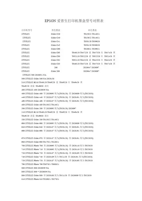
EPSON爱普生打印机墨盒型号对照表打印机型号黑色墨盒彩色墨盒STYLUS Color C20 T013052 T014051STYLUS Color C40 T013052 T014051STYLUS Color C41 T038150 T039050STYLUS Color C43 T038150 T039050STYLUS Color C60 T028051 T029051STYLUS Color C63 T046150 T047250 蓝T047350 红T047450 黄STYLUS Color C80 T032150 T032250 蓝T032350 红T032450 黄STYLUS Color C82 T032150 T042250 蓝T042350 红T042450 黄STYLUS Color C83 T046150 T047250 蓝T047350 红T047450 黄STYLUS 200 S020047 S020097STYLUS Color 200 S020047 S020097STYLUS 300 S020031 NA300 STYLUS Color 300 NA S020138310 STYLUS R310 T049150 T049250 蓝T049350 红T049450 黄T049550 淡蓝T049650 淡红400 STYLUS 400 S020039 NA400 STYLUS Color 400 原S020093现为(T050150) 原S020089现为(T052050)440 STYLUS Color 440 原S020187现为(T050150) 原S020191现为(T052050)460 STYLUS Color 460 原S020187现为(T050150) 原S020191现为(T052050)480 STYLUS Color 480 T013052 T014051500 STYLUS Color 500 原S020093现为(T050150) S020097510 STYLUS R510 T049150 T049250 蓝T049350 红T049450 黄T049550 淡蓝T049650 淡红580 STYLUS Color 580 T013052 T014051600 STYLUS Color 600 原S020093现为(T050150) 原S020089现为(T052050)640 STYLUS Color 640 原S020187现为(T050150) 原S020191现为(T052050)660 STYLUS Color 660 原S020187现为(T050150) 原S020191现为(T052050)670 STYLUS Color 670 原S020187现为(T050150) 原S020191现为(T052050)680 STYLUS Color 680 T017051 T018051700 STYLUS Photo 700 原S020093现为(T050150) 原S020110现为T053050710 STYLUS Photo 710 原S020093现为(T050150) 原S020110现为T053050720 STYLUS Photo 720 原S020187现为(T050150) 原S020193现为T053050740 STYLUS Color 740 原S020189现为T051150 原S020191现为(T052050)750 STYLUS Photo 750 原S020187现为(T050150) 原S020193现为T053050790 STYLUS Photo 790 T007051 T008051800 STYLUS 800 S020039 NA800 STYLUS 800 + S020039 NA800 STYLUS Color 800 原S020108现为T051150 原S020089现为T052050810 STYLUS Photo 810 T026051 T027051820 STYLUS 820 S020047 S020049810 STYLUS Photo 830 T026051 T027051850 STYLUS Color 850 原S020108现为T051150 原S020089现为T052050 860 STYLUS Color 860 原S020189现为T051150 原S020191现为(T052050) 870 STYLUS Photo 870 T007051 T008051875 STYLUS Photo 875 T007051 T008051880 STYLUS Color 880 T019051 T020051890 STYLUS Photo 890 T007051 T008051895 STYLUS Photo 895 T007051 T008051900 STYLUS Color 900 T003052 T005051950 STYLUS Color 950 T033150T033250 蓝T033350 红T033450 黄T033550 淡蓝T033650 淡红980 STYLUS Color 980 T003052 T0050511000 STYLUS 1000 S020039 NA1000 STYLUS 1000C S020039 NA1160 STYLUS Color 1160 原S020189现为T051150 原S020191现为(T052050) 1200 STYLUS Photo 1200 原S020187现为(T050150) T0010511270 STYLUS Photo 1270 T007051 T0090511290 STYLUS Photo 1290 T007051 T0090511500 STYLUS 1500 / 1500C S020062 S0200491520 STYLUS Color 1520 原S020108现为T051150 原S020089现为T052050 2000 STYLUS Color 2000 原S020189现为T051150 原S020191现为(T052050) 2100 STYLUS P2100 T034150T034250 黄T034350 红T034450 蓝T034550 淡红T034650 淡蓝T034750 淡黑T034850 消黑2500 STYLUS Color 2500 原S020189现为T051150 原S020191现为(T052050) 3000 STYLUS Color 3000 S020118S020122 黄S020126 红S020130 蓝5000 STYLUS Pro 5000 S020118S020122 黄S020126 红S020130 蓝S020143 淡红S020147 淡蓝5100 STYLUS CX5100 T032150T042250 蓝T042350 红T042450 黄STYLUS Photo 原S020093现为T050150 原S020110现为T053050EX STYLUS Photo EX 原S020093现为T050150 原S020110现为T053050 EX2 STYLUS Photo EX2 原S020093现为T050150 原S020110现为T053050 EX3 STYLUS Photo EX3 原S020187现T050150 原S020193现T053050XL STYLUS PRO / PRO XL S020034 S020036XL STYLUS PRO XL+ S020034 S020066II STYLUS Color II / IIS S020047 S020049EPSON爱普生打印机硒鼓/碳粉型号对照表EPL-2020 成像盒(S051090)EPL-N2500/N2500N 成像盒(S051090)大容量纸盒C802002双面打印单元C813982 Ethernet 10/100 Base Tx C823914EPL-6200 碳粉盒C13S050167 C13S050166 成像单元(C13S051099)EPL-6200L 碳粉盒(C13S050167) 成像单元(C13S051099)Aculaser-C900碳粉盒(黑色)S050100 碳粉盒(黄色)S050097碳粉盒(洋红色)S050098 碳粉盒(青色)S050099成像盒S051083 废碳粉收集器S050101 传送带单元S053009Aculaser-C1900 碳粉盒(黑色)S050100 碳粉盒(黄色)S050097碳粉盒(洋红色)S050098 碳粉盒(青色)S050099成像盒S051083 废碳粉收集器S050101 传送带单元S053009Aculaser-C4000 碳粉盒(黑色)C13S050091 碳粉盒(黄色)C13S050088碳粉盒(洋红色)C13S050089 碳粉盒(青色)C13S050090成像单元C13S051081 传送带单元S053006 加热组件S053007Aculaser-C4100 碳粉盒(黄色) C13S050148 碳粉盒(洋红色) C13S050147碳粉盒(青色) C13S050146 碳粉盒(黑色) C13S050149 成像单元C13S051093 加热组件C13S053012 传送带单元C13S053006Aculaser-C7000 粉盒(黄)S050039/S050079 粉盒(洋红)S050040/S050080 粉盒(青)S050041/S050081 粉盒(黑)S050038/S050082 成像盒S051082 废粉收集器S050020Aculaser-C8600粉盒(黄) S050039/S050079 粉盒(洋红) S050040/S050080粉盒(青) S050041/S050081 粉盒(黑) S050038/S050082成像盒S051082 废粉收集器S050020EPL-5700展业星碳粉盒SO50010 成像盒S051055EPL-5700L展业星(超值型) 碳粉盒SO50010 成像盒S051055EPL-5800展业星(超强型) 碳粉盒SO50010 成像盒S051055EPL-5800L 碳粉盒S050010 成像盒S051055EPL-5900 碳粉盒S050087 成像盒S051055EPL-5900L 碳粉盒S050087 成像盒S051055EPL-C8000创先机粉盒(黄) S050016粉盒(洋红) S050017 粉盒(青) S050018 粉盒(黑) S050019成像盒S051061 定影器油辊S052002 废粉收集器S050020EPL-C8200创先机(第二代) 粉盒(黄)S050016 粉盒(洋红) S050017 粉盒(青) S050018 粉盒(黑)S050019 成像盒S051061EPL-N1610天网通成像盒6,000页2 S051069EPL-N2000K 碳粉盒S051035EPL-N2010智网通成像盒S051069EPL-N4000+商捷通成像盒S051060EPL-N1210 成像盒S051069Aculaser-C1000 碳粉盒(黑色) S050033 碳粉盒(黄色) S050034碳粉盒(洋红色) S050035 碳粉盒(青色) S050036成像盒(包括废粉收集器) S051072Aculaser-C2000碳粉盒(黑色) S050033 碳粉盒(黄色) S050034 碳粉盒(洋红色) S050035碳粉盒(青色) S050036 成像盒(包括废粉收集器) S051072加热组件(220V) S053003 定影器油辊S052003废粉收集器S050037 传送带单元S053001Aculaser-C8500粉盒(黄) S050039 粉盒(青) S050081(新)/S050041(旧)粉盒(洋红) S050080(新)/S050040(旧)粉盒(黑) S050038成像盒S051073 废粉收集器S050020EPL-1220 S051079EPL-N2120 S051077EPL-6100 碳粉盒S050087、S050095 成像盒S051055EPL-6100L碳粉盒S050087、S050095 成像盒S051055超能复印打印机EPSON STYLUS CX5100 黑色墨盒T0321 彩色墨盒T0422/T0423/T0424EPSON STYLUS CX3100 黑色墨盒T028 彩色墨盒T029Stylus Photo RX510 黑色墨盒T0491 彩色墨盒T0492 / T0493 / T0494 / T0495 / T0496 StylusScan2500 黑色墨盒S020189 彩色墨盒S020191HP 耗材型号对照表一、HP 黑白激光打印机型号对应耗材型号HP 1000 HP C7115AHP 1012 HP Q2612AHP 1100 HP C4092AHP 1150 HP Q2624A 、HP Q2624XHP 1200 HP C7115AHP 1300 HP Q2613AHP 2100 HP C4096AHP 2200 HP C4096AHP 2300 HP Q2610AHP 4 Plus/m Plus HP 92298X、HP 92298A HP 4/4m HP 92298X、HP 92298AHP 4000 HP C4127A 、HP C4127XHP 4050 HP C4127A 、HP C4127XHP 4100 HP C8061A、HP C8061XHP 4200 HP Q1338AHP 4300 HP Q1339AHP 4L/mL HP 92274AHP 4p/mp HP 92274AHP 4si HP 92291A、HP 92291XHP 4v/mv HP C3900AHP 5/m/n HP 92298X、HP 92298AHP 5000 HP C4129XHP 5100 HP C4129XHP 5L HP C3906AHP 5p/mp HP C3903AHP 5si HP C3909A、HP C3909XHP 6L HP C3906AHP 6p/mp HP C3903AHP 8000 HP C3909A、HP C3909XHP 8150 HP C4182XHP 9000 HP C8543XHP IId HP 92295AHP III HP 92295AHP IIId、IIIp HP 92295AHP IIIsi HP 92291AXHP IIp Plus HP 92275AHP IIp、Series II HP 92275A二、HP 彩色激光打印机型号对应耗材型号HP 1500 /2500 黑(C9700A) 青(C9701A) 成像鼓(C9704A) 品红(C9703A) 黄(C9702A)HP 3500 青(Q2671A) 品红(Q2673A) 黄(Q2672A) 黑(Q2670A)HP 3700 黑(Q2670A) 青(Q2681A) 品红(Q2683A) 黄(Q2682A)HP 4500/4550 黑(C4191A) 青(C4192A) Drum Kit (C4195A) Fuser Kit/110-volt (C4197A)Fuser Kit/220-volt (C4198A) 品红(C4193A) 传输单元(C4196A) 黄Toner Cart (C4194A)HP 4600 黑(C9720A) 青(C9721A) 成像传输单元(C9724A) 品红(C9723A) 黄(C9722A)HP 5/5m 青(C3102A) 品红(C3104A) 黄(C3103A) Color LJet (C3968A)HP 5500 黑(C9730A) 青(C9731A) 成像Fuser Kit/110-volt (C9735A)成像传输单元(C9734A) 品红(C9733A) 黄(C9732A)HP 8500/8550 黑(C4149A) 青(C4150A) Drum Kit (C4153A)品红(C4151A) 传输单元(C4154A) 黄(C4152A)HP 9500 黑(C8560A) 青(C8561A) 青(C8551A) 传输单元(C8555A)品红(C8553A) 黄(C8562A)三、HP 彩色喷墨打印机型号对应耗材型号HP 2000c 黑墨(C4844A) 青墨(C4841A) 红墨(C4843A) 黄墨(C4842A)HP 2500c Pro 黑墨(C4844A) 青墨(C4841A) 红墨(C4843A) 黄墨(C4842A)HP 1100 青墨(C4836AN) 红墨(C4837AN) 黄墨(C4838AN)HP 2200/2250 黑墨(C4844A) 红墨(C4843A) 黄墨(C4842A) 青墨(C4836AN) 红墨(C4837AN) 黄墨(C4838AN)HP 2230/2280 黑墨(C4844A) 青墨(C4836AN) 红墨(C4837AN) 黄墨(C4838AN)HP 2300/2600 黑墨(C4844A) 青墨(C4836AN) 红墨(C4837AN) 黄墨(C4838AN)HP 3000 黑墨(C4844A) 青墨(C4804A) 红墨(C4805A) 黄墨(C4806A)HP 彩色Inkjet cp1160 黑色打印头(C4920A) 青头(C4921A) 红头(C4922A) 黄头(C4923A)HP 彩色Inkjet cp1700 黑墨(C4844A) 青墨(C4836AN) 红墨(C4837AN) 黄墨(C4838AN)HP Dj1000c 三色墨盒(51641A) 黑墨(51645A)HP Dj1100c 三色墨盒(51641A) 黑墨(51645A)HP Dj1120c 三色墨盒(C1823D) 三色墨盒2 pack (C1823T) 黑墨(51645A)HP Dj1200c 黑墨(51640A) 青墨(51640C) 红墨(51640M) 黄墨(51640Y)HP Dj1220c 黑墨(C4844A) 黑墨(51645A) 三色墨盒(C6578DN) 三色墨盒/大(C6578AN)HP Dj1600c 青墨(51640C) 红墨(51640M) 黄墨(51640Y) 黑墨(51645A)HP Dj310 三色墨盒(51625A) 黑墨(51626A) 595页黑墨(51633M)HP Dj320 三色墨盒(51625A) 黑墨(51626A) 黑墨(51633M)HP Dj3300 黑墨(C8727AN) 220 页HP Dj340 三色墨盒(51625A) 黑墨(51626A) 黑墨(51633M)HP Dj3400 黑墨(C8727AN) 三色墨盒(C8728AN)HP Dj3520 黑墨(C8727AN) 三色墨盒(C8728AN)HP Dj3550 黑墨(C8727AN) 三色墨盒(C8728AN) 照片墨盒(C6658AN)HP Dj3600 黑墨(C8727AN) 三色墨盒(C8728AN) 照片墨盒(C6658AN)HP Dj3820 黑墨(C6615DN) 三色墨盒(C6578DN) 三色墨盒/大(C6578AN)HP Dj400 三色墨盒(51625A) 黑墨(51626A) 黑墨(51633M)HP Dj420 三色墨盒(51625A) 黑墨(51626A) 黑墨(51633M)HP Dj500 三色墨盒(51625A) 黑墨(51626A)HP Dj510 黑墨(51626A)HP Dj5100 黑墨(C8727AN) 三色墨盒(C8728AN) 黑墨(C6656AN) 三色墨盒(C6657AN) 照片墨盒(C6658AN)HP Dj520 黑墨(51626A)HP Dj540 三色墨盒(51625A) 黑墨(51626A)CANON佳能对照表打印机型号对应耗材型CANON KT 佳能EP-KCANON LBP-460/LBP-660/LBP-465/LBP-210/LBP-310 EP-A 硒鼓鼓粉一体CANON FAX L770 佳能FX-1CANON FAX L500/L600/L630 佳能FX-2CANON FAX L250/L280/L380/L388/L350/L200/L350J 佳能FX-3CANON L800/L900 佳能FX-4CANON FC250/FC310/FC330/FC380 佳能E-16CANON FC200/FC210/FC220/FC230/FC240 佳能E-16CANON BX 佳能EP-BIICANON LBP—1760 佳能EP-52硒鼓,每盒打印10000页CANON BJC-8200 BCI-5BK 黑色墨盒BCI-5C兰色墨盒BCI-5M红色墨盒BCI-5Y黄色墨盒BCI-5PC照片兰色BCI-5PM照片红色CANON BJC-600,BJC-600E,BJC-610,BJC-620 BJI-201BK黑BJI-201C兰BJI-201M红BJI-201Y黄CANON BJ-300,BJ-330 BJI-642 黑色墨盒CANON FAX-B210,FAX-B180 BC-20 黑色墨盒,带喷头BC-21E 彩色墨盒CANON BJC-7000,BJC-7100,BJC-8000 BC-60墨盒黑色,900页BC-61E三色墨盒,带喷头BC-62E六色墨盒,带喷头CANON BJC-3000,BJC-6000/6100/6200,BJC-6500 BCI-3eBK黑BCI-3eC兰BCI-3eM 红BCI-3eY黄色墨盒BCI-3ePBK 照片黑色BCI-3ePC照片兰色BCI-3ePM 照片红色BCI-3ePY照片黄色BC-30e黑BC-31e彩BC-32e照片墨盒BC-33e彩色墨盒BC-34e照片墨盒CANON BJC-5000 四色墨盒BC-21e,四色Photo 墨盒BC-22e 和黑色墨盒BC-23CANON BJC-4650,BJC-5500,MPC70 BC-20黑,带喷头BC-21E彩BC-22E彩,带喷头CANON BJC-4200,BJC-4310SP,BJC-4550 BC-20 黑色墨盒,带喷头BC-21E 彩色墨盒BC-22E 彩色,带喷头CANON BJC-400,BJC-4000,BJC-4100 BC-20 黑色墨盒,带喷头BC-21E 彩色墨盒BC-22E 彩色,带喷头CANON BJC-2000SP,BJC-2100SP BC-20 黑色墨盒,带喷头BC-21E 彩色墨盒CANON BJC-240,BJC-250,BJC-255sp,BJC-1000sp BC-03黑BC-05彩BC-06照片CANON BJC-200,BJC-210S,BJC-210SP BC-03 黑色墨盒BC-05彩色墨盒Canon BJ-5 BC-01 黑色墨盒BC-05 彩色墨盒CANON LBP-2000 EP-65 硒鼓CANON LBP-1210 EP-25 硒鼓CANON LBP-800,LBP-810,LBP-1120 EP-22 硒鼓Canon i865 BCI-3eBK黑BCI-6BK黑BCI-6C青BCI-6M品红BCI-6Y黄CANON i560 BCI-3eBK黑BCI-6C青BCI-6M品红BCI-6Y黄色CANON S400,S400SP,S450,S4500,S600 BCI-3eBK黑BCI-3eC兰BCI-3eM 红BCI-3eY黄BCI-3ePBK 照片黑色BCI-3ePC照片兰色BCI-3ePM 照片红色BCI-3ePY照片黄BC-30e黑色墨盒BC-31e彩BC-32e 照片BC-33e彩色墨盒BC-34e照片墨盒CANON i70,i80 BCI-15BK黑色墨盒BCI-15CL彩色墨盒CANON S300,XNUI320,MPC190,S330,MPC200,i475D BCI-24B黑BCI-24C彩CANON i470D,MP360,S200SPX,MP390,i450 BCI-24B黑色墨盒BCI-24C彩色墨盒CANON i255,i355,i455,MPC190s BCI-24B黑色墨盒BCI-24C彩色墨盒CANON i990/i9950 BCI-6BK黑BCI-6C青BCI-6M品红BCI-6Y黄BCI-6PM照片品红BCI-6PC照片青BCI-6R橙墨盒BCI-6G绿墨盒CANON S800/S900/S820D/S830D BCI-6BK黑BCI-6C青BCI-6M品红BCI-6Y黄BCI-6PM照片品红墨盒BCI-6PC照片青色墨盒CANON i950/i950D/i9100 BCI-6BK黑BCI-6C青BCI-6M品红BCI-6Y黄BCI-6PM照片品红墨盒BCI-6PC 照片青色墨盒CANON BJC-80,BJC-85,BJC-85W BC-10黑BC-11彩BC-11e彩BC-12e照片墨盒BCI-10BK黑BCI-11BK 黑BCI-11C彩CANON BJ-30,BJC-50,BJC-55 BC-10黑BC-11彩BC-11e彩BC-12e照片墨盒BCI-10BK黑色墨盒BCI-11BK黑色墨盒BCI-11C彩色墨盒CANON BJC-1000SP BC-03黑色墨盒BC-05彩色墨盒BC-06照片墨盒CANON BJC-5500 BC-20黑BC-21e彩BC-22e照片BCI-21B黑BCI-21C彩CANON S100SP/BJC-4650 BC-20黑BC-21e彩BC-22e照片BCI-21B黑BCI-21C彩CANON BJC-2100SP BC-20黑BC-21e彩BC-22e照片BCI-21B黑BCI-21C彩SAMSUNG三星打印机耗材对照表打印机型号对应墨盒/硒鼓SCX-5112/5312F/5115/5315FSF-830,ML-912 硒鼓SCX-5312D6或SCX-5315R2ML-1650/1651N 硒鼓ML-1650D8SF-555P 硒鼓SF-550D3ML-5200A 硒鼓ML-5200D6ML-2150/2151N/2152W 硒鼓ML-2150D8ML-1440,1450,1451N 硒鼓ML-1450D6SF-5800 硒鼓SF-5800D5ML-808; SF-5100/5100P; SF-530/550 硒鼓ML-5100D3ML-4500 硒鼓ML-4500D3 3,000页SCX-4016/4116/4216F 硒鼓ML-1710D3ML-1510/1710/1750 硒鼓ML-1710D3ML-1210,1220M,1430,1250 硒鼓ML-1210D3SCX-1300/1350F,MJC-6000 黑色墨盒M90 彩色墨盒C90 照片墨盒P90MJC-4000/5000/6000/ SCX-1220 黑色墨盒M85 220页彩色墨盒C85SF-350 黑色墨盒M55(大容量)SF3100/SF3200系列,SF-430 黑墨M50 彩C50 或黑墨利盟1970 彩墨利盟15M0020传真机SF-330/331P/335T 黑色墨盒M40 彩色墨盒C40SF3000/3100/3100P/4000/4100/4200 黑色墨盒12A1145 彩色墨盒12A1140。
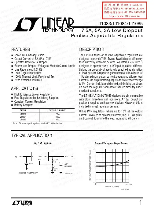
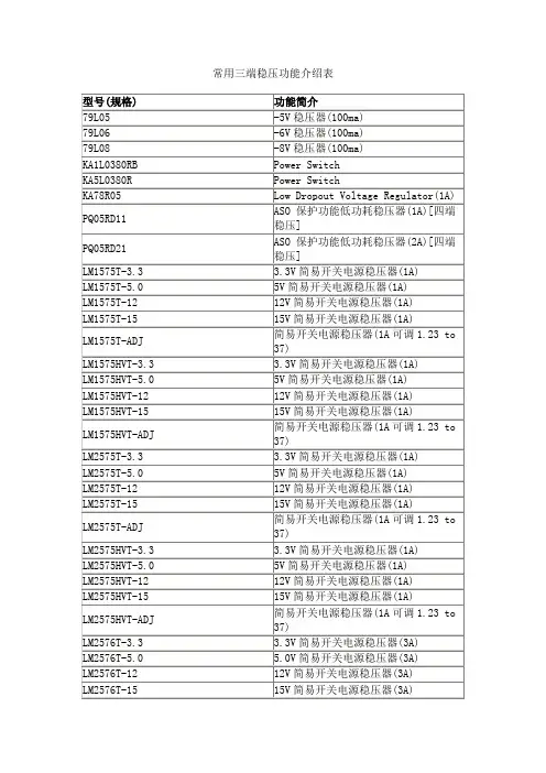
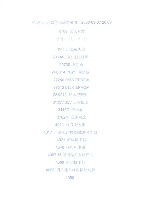
常用电子元器件用途索引表2008-03-07 20:09分类:嵌入开发字号:大中小741 运算放大器2063A JRC杜比降噪20730 双功放24C01AIPB21 存储器27256 256K-EPROM27512 512K-EPROM2SK212 显示屏照明3132V 32V三端稳压3415D 双运放3782M 音频功放4013 双D触发器4017 十进制计数器/脉冲分配器4021 游戏机手柄4046 锁相环电路4067 16通道模拟多路开关4069 游戏机手柄4093 四2输入施密特触发器409841256 动态存储器52432-01 可编程延时电路56A245 开关电源5G0401 声控IC5G673 八位触摸互锁开关5G673 触摸调光5G673 电子开关6116 静态RAM6164 静态RAM65840 单片数码卡拉OK变调处理器7107 数字万用表A/D转换器74123 单稳多谐振荡器74164 移位寄存器7474 双D触发器7493 16分频计数器74HC04 六反相器74HC157 微机接口74HC405374HCU04 六反相器74LS00 与门74LS00 4*2与非门74LS00 四2与非门74LS00 与门74LS04 6*1非门74LS08 4*2与门74LS11 三与门74LS123 双单稳多谐振荡器74LS123 双单稳多谐振荡器74LS138 三~二译码器74LS142 十进制计数器/脉冲分配器74LS154 4-16线译码器74LS157 四与或门74LS161 四2计数器74LS161 十六进制同步计数器74LS161 四~二计数器74LS164 数码管驱动74LS18 射频调制器74LS193 加/减计数器74LS193 四2进制计数器74LS194 双向移位寄存器74LS27 4*2或非门74LS32 四或门74LS32 4*2或门74LS374 八位D触发器74LS374 三态同相八D触发器74LS37774LS48 7位LED驱动74LS73 双J-K触发器74LS74 双D触发器74LS85 四位比较器74LS90 计数器75140 线路接收器75141 线路接收器75142A 线路接收器75143A 线路接收器7555 时钟发生器79MG 四端负稳压器8051 空调单片机8338 六反相器A1011 降噪ACVP2205-26 梳状滤波视频处理AD536 专用运放AD558 双极型8位D-A(含基准电压)变换器AD558 双极型8位D-A(含基准电压)变换器AD574A 12比特A/D变换器AD650AD670 8比特A/D变换器(单电源)1995s-2、15 AD7523 D-A变换器1994x-125AD7524 D-A变换器1994x-126AD7533 模数转换器1994x-141AD7533 模数转换器1995s-184ADC0804 8比特A/D变换器1995s-2、20ADC0809 8CH8比特A/D 1995s-2、23ADC0833 A/D变换4路转换器1995s-2ADC80 12比特A/D变换器1995s-2、8 ADC84/85 高速12比特A/D变换器1995s-2 AG101 手掌游戏机1993x-155AM6081 双极型8位D-A变换器1994x-127 AMP1200 音频功放皇后1993s-104AN115 立体声解码1991-135AN2510S 摄象机寻象器1994x-109AN2661NK 影碟机视频1995s-45AN2662K 时基校正(模拟)1995s-45AN2664FBP 影碟机视频1995s-45AN2664NK 影碟机视频1995s-45AN2870 影碟机伺服1995s-45AN3100N 射频调制器1991-55AN362 立体声解码1991-135AN363N 立体声解码1991-135AN3890FBS 影碟机主轴电机驱动1995s-45 AN3891FBP 影碟机主轴电机驱动1995s-45 AN5026K 红外接收1993x-106AN51354 中放/音频/视频解调1994s-255 AN5138K 图象通道1994-308AN5265 音频功放1994s-298AN5342K 亮度锐度加强电路1994s-243 AN5344FBP CFU地1995s-274AN5352 模拟开关1994-245AN5515 彩电场输出1995s-34AN5515 场输出1994-73AN5521 场输出电路1991-203AN5521 场输出1994-73AN5521 场输出1994-240AN5521 场扫描1994-308AN5600K 图象处理1994-308AN5612 色差解调1994s-245AN5652 伴音中放1994-308AN5862K PIP切换输出1994s-245AN6551 双运放1991-54AN6612 电机稳速1992-63AN6612S 杜比降噪1995s-43 AN6650 电机稳速1991-183AN6650 电机稳速1992-7AN6650 电机稳速1992-83 AN6650 电机稳速1992-127 AN6650 电机稳速1993s-165AN6913L 双运放1995s-85 AN7106K 单片放音机1992-63 AN7108 单片放音机1992-7 AN7108 单片放音机1992-127 AN7108 单片放音机1992-136 AN7108 单片放音机1993s-165 AN7110 音频功放1994x-107 AN7112E 音频功放1994s-39AN7158N 音频功放1991-3 AN7158N 音频功放1991-203 AN7168 双音频功放1991-195 AN7178 音频功放1994x-107 AN7188NK 双音频功放1992-14 AN7311 双前置放大1991-195 AN7315 双前置放大1992-99 AN7410 立体声解码1991-135AN74LS293 1994x-93AN7812 三端稳压器1994s-299AN78N05 三端稳压器1994s-298AP500/A DC功放驱动1995s-60AP500/A 双声道DC功放驱动1995s-156 AT24C01 存储器1994x-46ATC105 充电控制1993x-191 AX5212D 微机鼠标编码1994s-183 BA1035B 高速运放1994x-94BA1106F 放音前置放大及功放1995s-43 BA1310 立体声解码1991-135BA1320 立体声解码1991-135BA1330 立体声解码1991-135BA1335 立体声解码1991-135BA1404 调频发射1994x-183BA3015 电风扇电脑1994s-162BA3105 电风扇电脑1994x-58BA3212N 录放前置1994-180BA328 双前置放大1991-43BA328 低噪前置1992-58BA328 双声道前置放大1995s-189 BA3506 音频功放1991-139BA3822LS 5段均衡1994-180BA508 遥控电路1995s-171BA5102 音频前置1993x-108BA5102 遥控电风扇编码1995s-119 BA5104 电风扇遥控1995s-183BA527 音频功放1991-168BA5302 红外接收头1995s-183 BA5406 双功放1992-47BA6124 电平指示1991-31BA6209 录象机加载1991-11BA6209 主导电机驱动1994-192 BA6219B 加载电机驱动1994-120 BA6227 电机稳速1991-139BA6303 磁鼓控速1992-139BA6439P 主导电机驱动1994-120 BA728 双运放1992-91BA7751LS 录象机音频处理1993s-84 BA8105 遥控电风扇电路1995s-119 BA8206A4 电风扇控制1995s-183 BAS3108T FM发射1992-94 BGJ3302 四运放电压比较器1994-25 BH-SK-I 声控IC 1994s-175BH-SK-V 声控IC 1994x-74BISS0001 红外传感信号处理1995s-182 BL3102 时钟频率脉冲1994s-255BL3207 BBD延时1994s-255BL50462AP 遥控编码与发射1995s-299 BM5060 彩电CPU 1994-308BM5067 彩电CPU 1995s-212BM5069 彩电CPU 1995s-212BTS114 感温高速开关管1992-34BTS115 感温高速开关管1992-34BTS130 感温高速开关管1992-34BTS131 感温高速开关管1992-34BTS240 感温高速开关管1992-34BTS412 电源开关模块1992-112C036 4*2与非门1993s-93C043 双D触发器1993s-101C066C 4*2与非门1993x-147C1225H 音响驱动1992-198C1470 电机稳速1992-99C1490HA 红外接收1991-110C1676 超高频放大1995s-199C1891A 环绕声处理器1992-24C7642 单片收音机1991-95CA3069 运放1994x-184CA3160 1994x-188CA3193 音频运放1994x-36CA3524 脉冲调制1992-14CC14433 三位半A/D转换1991-46CC14433 三位半A/D转换1991-174CC4093 含施密特触发器的四2输入与非门1994s-44 CC4511 七段译码器1991-46CCU3000-17 从属微处理器1995s-299CCU3002-FDTV-11 彩电CPU 1995s-299CD1403 单运放1991-2CD4001 4*2或非门1993s-69CD4001 4*2或非门1994x-2CD4011 4*2与非门1993s-53CD4011 4*2与非门1993x-150CD4011 四2输入与非门1994s-80CD4013 双D触发器1991-2CD4013 双D触发器1993s-101CD4013 双D触发器1993x-6CD4013 双D触发器1994s-82CD4013 双D触发器1994x-22、54CD4017 十进制计数/分配1991-110CD4017 十进制计数/分配1993s-142CD4017 十进制计数译码器1994s-82 CD4017 十进制计数器/脉冲分配器1994s-34 CD4017 十进制计数器/脉冲分配器1994x-2 CD40174 六D触发器1992-130 CD4017B 十进制计数/分配1993x-173CD4017B 十进制计数器1995s-184CD40193B 双向可预置可逆计数器1994x-84 CD4020 14级二进制计数器1994s-80 CD4024 七位二进制串行计数器1994s-80 CD4028 二~十进制译码器1992-98CD4035 移位寄存器1994s-72CD4040 十二进制二进制计数器1992-22 CD4040 十二进制二进制计数器1993s-207 CD4040 12级二进制计数器1993x-125CD4040 12级二进制计数器1994s-80 CD4046 锁相环电路1994x-188CD4046 锁相环电路1995s-181CD4051 模拟开关1992-130 CD4051 模拟多路转换器1995s-2、35CD4052 四选一模拟开关1992-82CD4053 3*2模拟开关1992-62、207CD4053 3*2模拟开关1994x-54CD4053 3*2模拟开关1994x-126CD4053B TV/AV切换1994-219CD4053B 双向模拟开关1994-247CD4060 分频计数1993s-12CD4060 十四位计数器/分配器/振荡器1994s-30、40 CD4066 4*2模拟开关1992-112CD4066 4*2模拟开关1993s-91CD4066BE 四路模拟开关1994-269CD4067 模拟多路转换器1992-162CD4067 模拟多路转换器1995s-2CD4069 6*1非门1991-166CD4069 6*1非门1993s-45CD4069 6*1非门1993x-150CD4069 六非门1994s-4、82CD4071 4*2或门1994s-30CD4072 2-4输入或门1992-130CD4075 三或门1991-170CD4078 多输入或门1991-170CD4093 四与非门施密特触发器1994x-42 CD4099 8路可寻址锁存器1991-170CD4510 二~十加减计数器1992-98 CD4511 LED显示驱动1991-2CD4511 译码驱动1993x-159CD4511 译码显示1994s-30CD4514 4-10线译码器1993x-158CD4518 双二~十进制计数器1993x-125 CD4518 计数器1994s-30CD4541B 双D触发器1995s-79CD4553 三位BCD码计数器1993s-47 CD74206 音频功放1994x-107 CD9020-002 字符产生器1994s-255 CD9135 六路互复位触摸开关1994x-188 CE550 电风扇控制1994s-170CH1058 音乐片1991-192CH208 译码输出1991-174CH220 电子密码锁1994x-26CIC7642 调幅收音1994s-55CIC9140 电话按键码1993s-107 CNX82A2 稳压反馈光电耦合器1995s-299 CP4027 双J-K触发器1993s-109CS839 霍尔开关1994s-34CS8704 电话振铃1994-46CSC5089 单片电话机1994-77CTC9140 电话脉冲拨号1994-46CU001 多功能遥控1991-56CU47C433AN-002 彩电CPU 1994s-255 CW-18 呼救语音1993x-133CW8403 音乐IC 1993s-125CW9300 音乐IC 1993s-101CW9300 音乐IC 1993x-198CX20029 单片收音机1992-111CX20106 红外接收1993s-126CX20106 红外接收1994-230CX20106A 红外预放器1991-30CX20106A 红外接收1994x-22CX20111 调频调幅中放1992-127CX20112 电视立体声/多语种解码1994x-4 CX20188 杜比B/C降噪1992-174CX522-054 彩电CPU 1994s-302CX7959 存储器1994s-307CXA1019 单片收音机1991-114CXA1019 单片调频收音1991-152CXA1019 调频静噪1995s-52CXA1019M 单片收音机1994-74CXA1019P 单片调频收音1993x-85CXA1034P 单片放音机1992-83CXA1100 杜比降噪1991-106CXA1101 杜比降噪1991-106CXA1101 杜比降噪1992-108CXA1102 杜比降噪1991-106CXA1145P 游戏机色处理1991-131CXA1145P PAL编码1993x-78CXA1191M 调幅调频电视单片收音1993x-158 CXA1191M 单片收音机1994s-198 CXA1191M 单片调频调幅收音1994x-63 CXA1191P 收音专用1994-11CXA1238 单片收音机1991-140CXA1238M 调频收音1994s-130CXA1238M 调频收音1994s-156CXA1250 场频驱动1993x-103CXA1262N 单片放音机1993x-99CXA1315M 彩电副总线1995s-272CXA1642 消歌声1993s-64CXA1642 消声(卡拉OK)1995s-36CXA1642 消歌声1995s-204CXA1644P 卡拉数字延时1993x-72CXA1735S 音频处理器1995s-272CXA8008P 单片放音机1991-75CXA8008P 单片收音机1992-163CXD1254AQ 摄象机同步1993x-103CXD1310BLA 视频处理器1993x-103CXK1001P 存储器1994-307CXP80420-139S 彩电CPU 1994-334D1130 AM/FM收音1992-43D2024 音频功放1991-48D2283 音频低放1994s-135D2283 音频功放1994x-47D2822 助听器专用1991-167D414 单片收音机1991-167D7176AP 中放及伴音鉴频1994-19D7240AP 音频功放1991-3D75028CW 空调器CPU 1995s-194D7796 音频均衡1991-32DAC08 双极型8位D-A变换器1994x-129DAC08 双极型8位D-A变换器1994x-135DAC90 双极型8位D-A(含基准电压)变换器1994x-126 DBL2004 彩电场输出1995s-34DCM0016 系列高速带掉电保护RAM 1995s-174DCM0064 系列高速带掉电保护RAM 1995s-174 DCM0256 系列高速带掉电保护RAM 1995s-174 DCM8128 系列高速带掉电保护RAM 1995s-174 DJ2001 洗衣机电脑1991-159DN888 数字延迟1993x-110DPU-2553-25 偏转处理器1995s-299DRAM4164 数据存储1993s-80DS8629N 100分频器1992-22 DTI-2260 数字瞬态改善处理器1995s-299EA1062 语音电路1994-138EK001 混频厚膜1994s-255ELM742A 低压低功耗电压比较器1995s-118 ET91210 电话程控1991-58F1212 程序快门1992-71GL7488P 录象机伺服系统1994-210GP605 开关电源PWM脉宽调制1995s-126 GS8200 录象机系统控制1994-210GSE-3568 多音声效片1994s-128 GY65839 单片卡拉OK专用1994s-172 GY9308 DDC数码延迟1993x-120GY9403 数码卡拉OK延迟1994x-52H9081 四声5闪光片1994x-167HA11227 立体声解码1991-135HA112A 音乐门铃1991-156HA11414 行场扫描1993s-28HA11489 亮度/彩色矩阵1991-203HA11489 视频处理1994x-19HA11509N 亮/色/行场扫描1991-43HA1166Z 黑白机行场扫描1994-82HA12017 放音均衡1991-8HA12058 杜比降噪1993x-160HA12102 双前置放大1991-43HA13001 音频功放1993s-75HA13119 音频功放1994x-99HA1392 音频功放1992-188HA1397 音频功放1991-176HA3302 四运放电压比较器1994-25HA51338SP 亮/色/行场扫描1991-43HA51338SP 彩电行场扫描/色度/亮度1995s-163 HCF40015 红外接收前置放大1994s-118HD14053B 电视遥控发射1993x-164HD401304 彩电CPU 1995s-174HD401314 彩电CPU 1995s-174HD44007A 彩色同步1991-14HEF4017 2-10进制计数器/脉冲分配器1994x-22 HEF4053BP 3*2模拟开关1994s-7HEF4066B 四路模拟开关1994-269HEF4503 3*2模拟开关1992-207HF-268/288 保密语音模块1995s-94HFC3030 彩灯闪光片1994x-71HFC3040 多发光二极管控制1991-64HFC3040 彩灯六路闪光芯片1994s-50HFC5203A 语音1994x-90HFC5219 “有电危险、请勿靠近”语音块1995s-95 HIC101 放象机电源厚膜块1995s-85HM50256 动态存储器1995s-159HM50464 动态存储器1995s-159HM511000 动态存储器1995s-159HM6117 游戏存储1993s-11HM6232 电源厚膜1993x-35HM6401 电源/场输出厚膜1991-115HM7101 电源厚膜1993x-35HM7942 电源厚膜1993x-35HM8951 电源厚膜1993s-35HM8951A 电源厚膜1995s-99HM8951B 电源厚膜1993x-195HM8951B 电源厚膜1994-65HM9007 电子镇流器1991-82HM9007 电子镇流器1993s-146HM9102 电源厚膜1992-103HM9102 电源厚膜1993x-35HM9102 开关电源取样1994-141HM9102D 电话按键码1993s-107 HM911L 热释电红外线探测1994x-194 HM9201 电源厚膜1993x-35HM9205 稳压电源取样1994-332 HM9207 电源厚膜1993s-3HM9207 电源厚膜1994-65HM9207B 电子镇流器1994s-6HM-JL1 音频模块1993s-160HN6401 电源厚膜1993x-35 HPC177C 四运放电压比较器1994-25 HPC339C 四运放电压比较器1994-25 HT12C 遥控发射1994x-110HT2880 八音音乐片1994s-32HT6337A 风扇遥控接收1994x-110 HT7713 声控闪光片1994x-10HT7713 触摸调光1994x-63HT82D 双音音乐门铃1994s-32 HY12503 可程式化语音模块1995s-94HY-20A 语音录放1994s-78HY42503 可程式化语音模块1995s-94HY-88A 动物叫声效片1993x-182HY8-S 三端音乐片1991-172IC1818P 单片游戏机1993s-95IC7107 三位半A/D转换器1993x-181ICL7107 三位半A/D驱动1993s-62ICL7107 三位半模/数转换器1994s-80ICL7107 DVM三位半A/D 1995s-2、21 ICL7109 积分型12比特A/D变换器1995s-2 ICL7139 自动量程万用表1992-42ICL7660 双直流变换1993s-62ICL7660 DC-DC变换器1995s-39、68 ICL8038 函数发生器1994x-112 ICL8211 欠压检测用IC 1995s-40、89ICM7555 时基电路1995s-46ICM7556 时基电路1995s-40ICWJ9301 电脑密码锁1994s-190ICX045BLA 1/3寸CCD图象传感器1993x-103 IR2155 日光灯电子镇流模块1995s-38IR3M02 微机开关电源1994s-109IR3M03A DC-DC变换1992-86IR3M03A DC-DC变换1993s-119 ISD1000A 系列单片语音录放IC 1995s-174 ISD1100 系列单片语音录放IC 1995s-174 ISD1400 系列单片语音录放IC 1995s-174 ISD2500 系列单片语音录放IC 1995s-174 IVR1601 一次性编程语音1993s-159 IX0238CE 场输出1994-73IX0250CE 音频功放1994-73IX0256CE 开关电源1994-73IX0308 电源厚膜1992-127IX0308CZ 电源厚膜1994-67IX0323CD 电源厚膜1994s-3IX0323CE 电源厚膜1994-33IX0324CFNI 行场扫描/色解码1994-34 IX0355CE 场输出1994-73IX0465CE 开关电源1994-73IX0517CE 开关电源1994-73IX0640CE 场输出1994-73IX0689CE 电源厚膜1994-48IX0711CE 彩电中放1994-73IX0711CEN 图象中放1994x-83IX0712CE 亮/色/行场扫描1994-73IX0712CEN1 扫描/解码1994-96IX0933CE 彩电CPU 1994-96JU0114 电源厚膜1991-155JU0114 彩电电源厚膜块1995s-43、51 JU0116 电源厚膜1994-66K2356 语音保密1992-178KA2184A 红外预放器1991-30KA2184A 红外线接收预放1991-56KA2184A 红外接收1993s-126KA2184A 红外接收放大1993x-170 KA2209 音频功放1993x-43KA22134 音频功放1994x-83KA2221 双前置放大1991-43KA22429 调频收音1994s-55KA2402 电机稳速1993x-99KA2402 电机稳速1995s-131KA2407 电机稳速1993x-43KA2410 电话振铃1994x-11KA2410 电话振铃1994-138KA2915 单片黑白电视机1993s-167KAC4558 双运放1991-71KD-07 闪光灯、音乐集成块1995s-71 KD-100 音乐IC 1993x-5KD-152B 音乐IC 1993x-189KD-155 口哨声控片1995s-183KD-253 “叮咚”门铃1994x-194KD-253B “叮咚”门铃1994s-62KD-254 音乐片1994s-143KD482FB 石英钟报时1991-4KD-482FC 钟控打点1993s-142 KD483 程控双音打点石英钟1994s-175 KD5068 狗叫声音乐片1993x-126 KD5105 电子爆竹1993s-38KD-5601 爆竹声1993x-189KD56010 “恭喜发财”语音片1994x-138 KD56012 鸟叫声1993s-157KD56012 鸟叫IC 1994x-143KD-5602 军号声音乐片1995s-191 KD5603 “欢迎光临”语音片1991-62 KD5603 欢迎光临1993s-142KD-5603 “欢迎光临”语音片1994s-63KD56032 六秒自然声1995s-143KD56033 娃娃哭笑语音块1995s-103 KD5604 谢谢光临1993s-142KD-5608 “狗叫”音乐片1992-168KD9300 音乐门铃1991-156KD9300 音乐门铃1994s-138KD9300 音乐门铃1994x-2、34KD9561 警车声音乐片1992-68KD9561 音乐IC 1994x-42KD9562B 警报声音乐1993x-52KD9562C 八声声效片1992-10KH1668 风扇控制1994x-154KIA6227H 音频功放1994-346KIA6299H 音频功放1994x-107KIA6401 电话振铃1994x-11KIA7299P 音频功放1994s-51KIA75558P 录象机伺服系统1994-210 KIA8125S 音频前置放大1994s-51KIA8127F AM/FM中放1994-180 KM41C64P-10 画中画DRAM 1995s-299 KS5194/5 液晶显示驱动1994x-66KS5803 红外遥控发射1991-56KS5803 红外发射1992-95KS5917 语音电路1993s-183L200 五端集成稳压器1994s-110 L4960 开关电源脉宽调制1995s-102 L4962 开关电源脉宽调制1995s-102 L4962 脉宽调制器1995s-152L4964 开关电源脉宽调制1995s-102 L4970 开关电源脉宽调制1995s-102 L4974 开关电源脉宽调制1995s-102 L78MR05 1994-240LA1231N FM解调1991-35LA1260 调频、调幅收音1994-104 LA3160 双前置放大1991-43LA3160 前置放大1994-340LA3350 立体声解码1991-135LA3361 立体声解码1991-66LA3361 立体声解码1991-135LA3365 立体声解码1991-135LA4127 双前置放大1993x-83LA4140 音频功放1993x-91LA4140 音频功放1994-137LA4275 音频功放1994s-255LA4422 音频功放1994-73LA4445 音频功放1991-67LA4445 音频功放1991-203LA4445 音频功放1993x-27LA4597 音频功放1993x-27LA5110 彩电稳压电源1995s-187LA5112 彩电稳压电源1995s-187LA5511 电机稳速1991-3LA5515 电机稳速1991-3LA5521D 电机稳速1995s-131LA7016 制式切换1995s-299LA7299 音频功放1991-67LA7555 中频信号处理1995s-342 LA7575 PLL同步检波中频解码1995s-299LA7680 图象/伴音中频/视放/解码1994-273、302 LA7830 场输出电路1991-203LA7830 场输出电路1992-39LA7830 场输出1994-73LA7832 彩电场输出1995s-27LA7832/33 场输出1994s-255LA7837 场输出1994s-299 1995-62LA7838 场输出1994-268LA7905 50Hz/60Hz识别1994s-255LA7910 波段开关1994-248LA7920 波段开关1994s-307LAG665 单片放音机1991-132LAG665 单片放音机1991-199LAG665 单片放音机1992-47LAG665 随身听IC 1994s-20LAG665 单片放音机1994x-83LAG665F 单片放音机1993x-109LAG665F 单片立体声放音1995s-12LB1405 电平指示1993x-154LB1407 电平指示1995s-55LC219 风扇红外遥控发射1993x-170LC219 红外发射编码1994-230LC220A 六路译码器1993x-170LC220A 红外译码1994-230LC4036 双向模拟开关1994s-255LC4066B 四路模拟开关1994-269LC7441 PIP系统控制1994s-245LC7444 双时钟发生器1994s-245LC7480 多路转换开关和模/数转换器1994s-245 LC7881 D/A转换1992-124LCL102 计程显示器1994s-34LD398C 卫视接收厚膜块1993x-157LD505 音频放大1992-141LD866A 雷达探测模块1994s-63LD866B 雷达探测模块1994s-63LF398 取样与保持1995s-2、29LH-169B “抓贼呀”语音片1994s-7LIC1149-5 降压控制器1994s-104LM010 1994x-192LM1035 音量、平衡、音调直流控制1993s-32 LM1036 音量、平衡、音调直流控制1993s-32 LM1040 音量、平衡、音调直流控制1993s-32LM12 运放1995s-30LM134 1994x-192LM1851N 漏电检测1994x-42LM1875 运算放大器1991-36LM1875 音频功放1994s-68LM1894 杜比降噪1991-106LM1894 动态降噪1991-200LM1894 降噪1993s-90LM1894 动态降噪1993s-170LM2575 开关电源脉宽调制1995s-102LM258 双前置放大1993x-43LM2904CT 三端稳压器1994s-168LM2907/2917 频率/电压转换器1994s-199 LM293X 低压差三端稳压器1995s-41LM311 专用运放比较器1994x-18LM317 三端可调稳压电源1991-103LM317 三端可调稳压电源1993s-124LM317 三端可调稳压电源1994s-4LM317 正压可调三端稳压1995s-39LM317T 可调三端稳压1991-186LM318N 高速运放1994x-128LM3272C 石英钟芯1992-35LM331 V/F变换器1995s-2、37LM337 负压可调三端稳压1995s-39、46LM339N 四运放电压比较器1994-25 LM3524A 开关电源脉宽调制1995s-102LM358 双运放1992-8LM358P 运放1995s-299LM358PS 录象机主导放大整形1994-120 LM35DZ 温度传感1992-198LM385 小功率基准电压1995s-39、60、76 LM386 音频功放1991-168LM386 音频功放1993s-6、77LM386N 音频功放1994x-90 LM3875T 单片功放1993s-146 LM3875T 音频功放1993x-144 LM3876T 单片功放1993s-146 LM389 调频发射1992-70LM3900 电流型四运放1994s-199 LM3909 单片振荡器1995s-63LM3909N 闪烁灯1995s-88LM3914 电平显示1993x-22LM3915 显示驱动1994x-16LM4280 音频功放1995s-299 LM567 频率解调1991-2LM567 音频解调1991-62LM567 红外音频解调1991-134 LM567 红外音频解调1994x-2 LM567 红外音频解调1994x-119 LM567 调频发射、接收1995s-143 LM6181 视频放大1994x-7LM723 通用型稳压块1994s-79 LM833 双运放1993s-170LM8361 数字钟1994x-162LM837 四运放1993s-170LMC1982 数控音响1993s-178LP167 环形脉冲分配/驱动1994s-122LP2950CZ 低压差5V稳压器(三端)1995s-88 LQ46 四合一语音片1992-76LQ46 语音片1994x-162LR3714AM 遥控发射1993x-156LR40993 电话机发号1995s-111LR6 低压线性稳压器1995s-94LS190 对数放大器1994x-77LS7232 触摸调光1991-100LS7232 触摸调光1993s-94LS7232 触摸调光1994x-142LS85 1994x-77LT1005 逻辑控制稳压器1995s-39LT1057 音频运放1991-120LT1073 充电检测控制1994s-56LT1173CS8 DC-DC变换器1994x-8。
MKE04P24M48SF0 KE04子系列数据手册支持以下产品:MKE04Z8VTG4(R)、MKE04Z8VWJ4(R)和MKE04Z8VFK4(R)主要功能•工作范围–电压范围:2.7至5.5 V–Flash编程电压范围:2.7至5.5 V–温度范围(环境):-40至105°C•性能–最高48 MHz的ARM® Cortex-M0+内核–单周期32位 x 32位乘法器–单周期I/O访问端口•存储器和存储器接口–最高8 KB的Flash–最高1 KB的RAM•时钟–振荡器(OSC) - 支持32.768 kHz晶振或4 MHz至24 MHz晶振或陶瓷谐振器;可选择低功耗或高增益振荡器–内部时钟源(ICS) - 内部FLL,集成内部或外部基准时钟源、37.5 kHz预校准内部基准时钟源,可用于48 MHz系统时钟–内部1 kHz低功耗振荡器(LPO)•系统外设–电源管理模块(PMC)有三个功率模式:运行、待机和停止–可复位、中断并带可选跳变点的低压检测(LVD)–带独立时钟源的看门狗(WDOG)–可配置循环冗余校验(CRC)模块–串行线调试(SWD)接口–SRAM位操作映射区域(BIT-BAND)–位处理引擎(BME)•安全性和完整性模块–每个芯片拥有80位唯一标识(ID)号•人机接口–最多22个通用输入/输出(GPIO)–两个8位键盘中断(KBI)模块–外部中断(IRQ)模块•模拟模块–一个12通道,12位SAR ADC,可工作在停止模式,可选硬件触发源(ADC)–两个包含6位DAC和可配置参考输入的模拟比较器(ACMP)•定时器–一个6通道FlexTimer/PWM (FTM)–一个2通道FlexTimer/PWM (FTM)–一个2通道周期性中断定时器(PIT)–一个脉宽计数器(PWT)–一个实时时钟(RTC)•通信接口–一个SPI模块(SPI)–一个UART模块(UART)–一个I2C模块(I2C)•封装选项–24引脚QFN–20引脚SOIC–16引脚TSSOPFreescale Semiconductor数据手册: 技术数据Rev 3, 3/2014 Freescale reserves the right to change the detail specifications as may berequired to permit improvements in the design of its products.© 2013 Freescale Semiconductor, Inc.目录1订购器件 (3)1.1确定有效的可订购器件 (3)2器件标识 (3)2.1说明 (3)2.2格式 (3)2.3字段 (3)2.4示例 (4)3参数分类 (4)4额定值 (4)4.1热学操作极限 (4)4.2湿度操作极限 (5)4.3ESD操作额定值 (5)4.4电压和电流操作额定值 (5)5通用 (6)5.1静态电气规格 (6)5.1.1DC特性 (6)5.1.2电源电流特性 (12)5.1.3EMC性能 (13)5.2动态规格 (14)5.2.1控制时序 (14)5.2.2FTM模块时序 (15)5.3热规格 (16)5.3.1热特性 (16)6模块工作要求和行为 (17)6.1内核模块 (17)6.1.1SWD电气规格 (17)6.2外部振荡器(OSC)和ICS特性 (18)6.3NVM规格 (20)6.4模拟 (21)6.4.1ADC特性 (21)6.4.2模拟比较器(ACMP)电气规格 (23)6.5通信接口 (24)6.5.1SPI开关规格 (24)7尺寸 (27)7.1获取封装尺寸 (27)8引脚分配 (27)8.1信号多路复用和引脚分配 (27)8.2器件引脚分配 (29)9修订历史 (30)订购器件1.1确定有效的可订购器件有效可订购器件编号已发布在网络上。
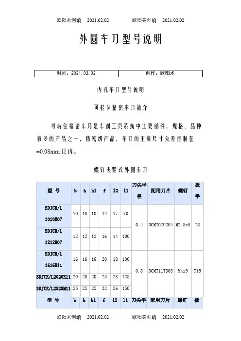
外圆车刀型号说明内孔车刀型号说明可转位精密车刀简介可转位精密车刀是车削工具系统中主要部件,规格、品种较多的产品之一,精密级产品,车刀的主要尺寸公差控制在±0.08mm以内。
螺钉夹紧式外圆车刀螺钉夹紧式外圆车刀SDJCR/L、SDPCN、SDPCR/L、SSDPN、STACR/L、SCGCR/L、SCFCR/L、SCLCR/L、SRDCN、SRGCR/L、SVJBR/L、SVVBN、SVHBR/L0808H09STACR/L10 10 10 101010H09STACR/L12 12 12 121212H09STAPR/L16 16 16 16 131616H11STAPR/LTCMT11020420 20 20 25 18 1252020K11STAPR/L25 25 25 32 25 1502525M11型号b h h1f l2l1刀尖半径配用刀片螺钉扳手0.4 CCMT060204 M2.5x5 T8 SCGCR/L 1212H0612 12 12 16 12100SCGCR/L 1616H0916 16 16 20 16SCGCR/L 2020K0920 20 20 25 25 1250.8 CCMT09T308 M4x9 T15 SCGCR/L 2525M0925 25 25 32 25 150螺钉夹紧式外圆车刀刀尖半型号b h h1f l2l1配用刀片螺钉扳手径SCFCR/L0.4 CCMT0602 M2.5x5 T812 12 12 161212H0616 100SCFCR/L16 16 16 201616H09SCFCR/L0.8 CCMT09T308 M4x9 T1520 20 20 25 25 1252020K09SCFCR/L25 25 25 32 25 1502525M09刀尖半型号b h h1f l2l1配用刀片螺钉扳手径SCLCR/L0.4 CCMT060204 M2.5x5 T812 12 12 16 121212H06100SCLCR/L16 16 16 20 161616H090.8 CCMT09T308 M4x9 T15 SCLCR/L20 20 20 25 25 1252020K09螺钉夹紧式外圆车刀螺钉夹紧式内孔车刀螺钉夹紧式内孔车刀S-STFPR/L、S-STUPR/L、S-STLPR/L、S-SSKPR/L、S-SCLCR/L、S-SDUCR/LSCLCR/L0932 25 17 250 40 23 22.5 6°型号最小加工直径Dd f l1l2H Bα°a刀尖半径配用刀片螺钉扳手S12M-SDUCR/L0716 12 9 150 25 11 11.5 8°7.0 0.4 DCMT070204 M2.5x5 T8 S16Q-SDUCR/L0720 16 11 180 30 14 15 6°S20R-SDUCR/L1125 20 13 200 35 18 18.5 8° 10.5 0.8 DCMT11T308 M4x9 T15复合上压式车刀型号b h.h1l1f l2a刀尖半径配用刀片复合上压式车刀型号 b h.h1 l1 f l2 a 配用刀片MSSNR/L20 20 125 252020K1234 8 SNMG120408 MSSNR/L25 25 150 322525M12MSSNR/L25 32 170 32 38 10 SNMG150612 3225P15型号f h1l2b h l1A配用刀片MRGNR/L25 2020 20 1252020K1228MRGNR/L?12 RNMG120432 25 25 25 1502525M12MRGNR/L32 32 32 25 32 1703225P12刀尖半型号f h1l2b h l1a配用刀片径MDPNN 10 20 45 20 20 125 12 0.8 DNMG150608复合上压式车刀MSBNR/L、MSDNN、MSKNR/L、MSSNR/L、MRGNR/L、MDPNN、MTGNR/L、MCLNR/L、MTFNR/L、MWLNR/L、MDJNR/L、MDHNR/L复合上压式车刀杠杆式车刀PSBNR/L、PSDNN、PSSNR/L、PCFNR/L、PSKNR/L、PCBNR/L、PTGNR/L、PCLNR/L、PTFNR/L、PDPNN、PDJNR/L、PDHNR/L、PRGNR/LPSSNR/L3225P1232 32 170 161.71.2SNMG150608 PSSNR/L4040R1950 32.5 40 40 40 40 200 187.5 12 SNMG190612杠杆式车刀型号f f1h1l2b h l1a刀尖半径配用刀片PCFNR/L2020K122518202820 20 12512 0.8 CNMG120408PCFNR/L2525M1232252525 150PCFNR/L3225P1232 32 170型号f f1h1l2b h l1l0a刀尖半径配用刀片PSKNR/L1616H0920 15 16 17 16 16 100 102 80.8SNMG090308 PSKNR/L 25 17 20 22 20 20 125 128 11 SNMG120408PSKNR/L2525M1232 25 25 25 150 153PSKNR/L3232P1540 22 32 30 32 32 170 174 13.51.2SNMG150612 PSKNR/L4040R1950 27 40 40 40 40 200 205 16.5 SNMG190612型号f h1l2b h l1a刀尖半径配用刀片PCBNR/L2020K1217 2028 20 20 12511 0.8 CNMG120408PCBNR/L2525M1222 252525 150PCBNR/L3225P1632 31 32 170 14.5 1.2 CNMG160612杠杆式车刀型号f f1h1l2b h l1a刀尖半径配用刀片PTGNR/L 20 16 16 22 16 16 100 14.5 0.8 TNMG160408杠杆式车刀切断(槽)刀型号说明QZQ1616RL、QZQ2020RL、QZQ2525RL、QZQ3225RL切断(槽)刀螺纹车刀型号说明外螺纹车刀型号hh1bLf配用刀片螺 钉 扳 手SE R/L 1616H16 16 16 16 100 20 16ER/L M3.5x14 T15SE R/L 2020K16 20 20 20 125 25SE R/L 2525M16 25 25 25 15032SE R/L 3225P16 32 32 25 170 SE R/L 3232P16 32 32 32 170 40 SE R/L 2525M22 25 25 25 150 32 22ER/L M4x15T20SE R/L 3225P22 32 32 25 170 32 SE R/L 3232P2232323217040内螺纹车刀SER/L,SNR/L。
1Gb Q-die DDR2 SDRAM Specification60FBGA & 84FBGA with Pb-Free & Halogen-Free(RoHS compliant)INFORMATION IN THIS DOCUMENT IS PROVIDED IN RELATION TO SAMSUNG PRODUCTS, AND IS SUBJECT TO CHANGE WITHOUT NOTICE.NOTHING IN THIS DOCUMENT SHALL BE CONSTRUED AS GRANTING ANY LICENSE, EXPRESS OR IMPLIED, BY ESTOPPEL OR OTHERWISE,TO ANY INTELLECTUAL PROPERTY RIGHTS IN SAMSUNG PRODUCTS OR TECHNOLOGY. ALL INFORMATION IN THIS DOCUMENT IS PROVIDEDON AS "AS IS" BASIS WITHOUT GUARANTEE OR WARRANTY OF ANY KIND.1. For updates or additional information about Samsung products, contact your nearest Samsung office.2. Samsung products are not intended for use in life support, critical care, medical, safety equipment, or similar applications where Product failure couldresult in loss of life or personal or physical harm, or any military or defense application, or any governmental procurement to which special terms or provisions may apply.* Samsung Electronics reserves the right to change products or specification without notice.Table of Contents1.0 Ordering Information (4)2.0 Key Features (4)3.0 Package Pinout/Mechanical Dimension & Addressing (5)3.1 x4/x8 package pinout (Top View) : 60ball FBGA Package (5)3.2 x16 package pinout (Top View) : 84ball FBGA Package (6)3.3 FBGA Package Dimension (x4/x8) (7)3.4 FBGA Package Dimension (x16) (8)4.0 Input/Output Functional Description (9)5.0 DDR2 SDRAM Addressing (10)6.0 Absolute Maximum DC Ratings (11)7.0 AC & DC Operating Conditions (11)7.1 Recommended DC Operating Conditions (SSTL - 1.8) (11)7.2 Operating Temperature Condition (12)7.3 Input DC Logic Level (12)7.4 Input AC Logic Level (12)7.5 AC Input Test Conditions (12)7.6 Differential input AC logic Level (13)7.7 Differential AC output parameters (13)8.0 ODT DC electrical characteristics (13)9.0 OCD default characteristics (14)10.0 IDD Specification Parameters and Test Conditions (15)11.0 DDR2 SDRAM IDD Spec Table (17)12.0 Input/Output capacitance (18)13.0 Electrical Characteristics & AC Timing for DDR2-800/667 (18)13.1 Refresh Parameters by Device Density (18)13.2 Speed Bins and CL, tRCD, tRP, tRC and tRAS for Corresponding Bin (18)13.3 Timing Parameters by Speed Grade (19)14.0 General notes, which may apply for all AC parameters (21)15.0 Specific Notes for dedicated AC parameters (23)Revision HistoryRevision Month Year History1.0September2007 - Initial Release1.01November2007 - Typo CorrectionSpeed DDR2-800 5-5-5DDR2-800 6-6-6DDR2-667 5-5-5Units CAS Latency 565tCK tRCD(min)12.51515ns tRP(min)12.51515ns tRC(min)57.56060nsNote :1. Speed bin is in order of CL-tRCD-tRP.2. RoHS Compliant.3. “H” of Part number(12th digit) stand for RoHS compliant and Halogen-free products.Org.DDR2-800 5-5-5DDR2-800 6-6-6DDR2-667 5-5-5Package 256Mx4K4T1G044QQ-HC(L)E7K4T1G044QQ-HC(L)F7K4T1G044QQ-HC(L)E660 FBGA 128Mx8K4T1G084QQ-HC(L)E7K4T1G084QQ-HC(L)F7K4T1G084QQ-HC(L)E660 FBGA 64Mx16K4T1G164QQ-HC(L)E7K4T1G164QQ-HC(L)F7K4T1G164QQ-HC(L)E684 FBGA•JEDEC standard 1.8V ± 0.1V Power Supply •VDDQ = 1.8V ± 0.1V•333MHz f CK for 667Mb/sec/pin, 400MHz f CK for 800Mb/sec/pin •8 Banks •Posted CAS•Programmable CAS Latency: 3, 4, 5, 6•Programmable Additive Latency: 0, 1, 2, 3, 4, 5•Write Latency(WL) = Read Latency(RL) -1•Burst Length: 4 , 8(Interleave/nibble sequential)•Programmable Sequential / Interleave Burst Mode •Bi-directional Differential Data-Strobe (Single-ended data-strobe is an optional feature)•Off-Chip Driver(OCD) Impedance Adjustment •On Die Termination•Special Function Support- PASR(Partial Array Self Refresh)- 50ohm ODT- High Temperature Self-Refresh rate enable •Average Refresh Period 7.8us at lower than T CASE 85°C, 3.9us at 85°C < T CASE < 95 °C •All of Lead-free products are compliant for RoHSThe 1Gb DDR2 SDRAM is organized as a 32Mbit x 4 I/Os x 8banks, 16Mbit x 8 I/Os x 8banks or 8Mbit x 16 I/Os x 8 banks device. This synchronous device achieves high speed double-data-rate transfer rates of up to 800Mb/sec/pin (DDR2-800) for general applications.The chip is designed to comply with the following key DDR2SDRAM features such as posted CAS with additive latency, write latency = read latency - 1, Off-Chip Driver(OCD) impedance adjustment and On Die Termination.All of the control and address inputs are synchronized with a pair of externally supplied differential clocks. Inputs are latched at the crosspoint of differential clocks (CK rising and CK falling). All I/Os are synchronized with a pair of bidirectional strobes (DQS and DQS) in a source synchronous fashion. The address bus is used to convey row, column, and bank address information in a RAS/CAS multiplexing style. For example, 1Gb(x8) device receive 14/10/3 addressing.The 1Gb DDR2 device operates with a single 1.8V ±0.1V power supply and 1.8V ±0.1V VDDQ.The 1Gb DDR2 device is available in 60ball FBGAs(x4/x8) and in 84ball FBGAs(x16).Note : The functionality described and the timing specifications included in this data sheet are for the DLL Enabled mode of operation.Note : This data sheet is an abstract of full DDR2 specification and does not cover the common features which are described in “DDR2 SDRAM Device Operation & Timing Diagram”.1.0 Ordering Information2.0 Key FeaturesNote:1. Pins B3 and A2 have identical capacitance as pins B7 and A8.2. For a read, when enabled, strobe pair RDQS & RDQS are identical in function and timing to strobe pair DQS & DQS and input masking function is disabled.3. The function of DM or RDQS/RDQS are enabled by EMRS command.4. VDDL and VSSDL are power and ground for the DLL.A B C D E F G H J K LVDD NU/VSSDQ6VSSQ VDDQ VDDQ VDDQ VSSQ VSSQ DQS DQS DQ7DQ0VDDQ DQ2VSSQ DQ5VSSDL VDD CK RAS CK CAS CS A2A6A4A11A8NCA13NCA12A9A7A5A0VDD A10/APVSSVDDQ VSSQ DQ1DQ3DQ4VDDLA1A3BA1VREF VSS CKEWE BA01 2 3 7 8 9VDDVSS ODTBA2Ball Locations (x4/x8): Populated Ball +: Depopulated BallTop View (See the balls through the Package)++++++++++++++++++++++++++++++123456789A B C D E F G H J K L++++++++DM /RDQSRDQS+3.1 x4/x8 package pinout (Top View) : 60ball FBGA Package3.0 Package Pinout/Mechanical Dimension & AddressingNote :1. VDDL and VSSDL are power and ground for the DLL.2. In case of only 8 DQs out of 16 DQs are used, LDQS, LDQSB and DQ0~7 must be used.A B C D E F G H J K L VDD NC VSS DQ14VSSQ UDM VDDQ VDDQ VDDQ VSSQ VSSQ UDQS UDQS DQ15DQ8VDDQ DQ10VSSQ DQ13VSSQ VDDQ RAS CK CAS CS A2A6A4A11A8NCNCNCA12A9A7A5A0VDDA10/APVSSVDDQ VSSQ DQ9DQ11DQ12VDD A1A3BA1NC VSS CKEWE BA0 1 2 3 7 8 9VDDVSSODTBA2Ball Locations (x16): Populated Ball +: Depopulated BallTop View (See the balls through the Package)M N P RDQ6VSSQ LDM VDDQ VDDQ VSSQ LDQS DQ7DQ0VDDQ DQ2VSSQ DQ5VSSDL VDD CK VDDQ VSSQ DQ1DQ3DQ4VDDLVREF VSS LDQS 123456789++++++++++++++++++++++++++++++++++++++++++++++++++A B C D E F G H J K L M N P R+3.2 x16 package pinout (Top View) : 84ball FBGA Package3.3 FBGA Package Dimension (x4/x8)A B CD E F H J K LG3.4 FBGA Package Dimension (x16)A B C D E FH J K L M N P RGSymbol Type FunctionCK, CK Input Clock:CK and CK are differential clock inputs. All address and control input signals are sampled on the crossing of the positive edge of CK and negative edge of CK. Output (read) data is referenced to the crossings of CK and CK (both directions of crossing).CKE Input Clock Enable: CKE HIGH activates, and CKE Low deactivates, internal clock signals and device input buffers and out-put drivers. Taking CKE Low provides Precharge Power-Down and Self Refresh operation (all banks idle), or Active Power-Down (row Active in any bank). CKE is synchronous for power down entry and exit, and for self refresh entry. CKE is asynchronous for self refresh exit. After V REF has become stable during the power on and initialization swquence, it must be maintained for proper operation of the CKE receiver. For proper self-refresh entry and exit, V REF must be maintained to this input. CKE must be maintained high throughout read and write accesses. Input buffers, excluding CK, CK, ODT and CKE are disabled during power-down. Input buffers, excluding CKE, are disabled during self refresh.CS Input Chip Select: All commands are masked when CS is registered HIGH. CS provides for external Rank selection on sys-tems with multiple Ranks. CS is considered part of the command code.ODT Input On Die Termination: ODT (registered HIGH) enables termination resistance internal to the DDR2 SDRAM. When enabled, ODT is only applied to each DQ, DQS, DQS, RDQS, RDQS, and DM signal for x4/x8 configurations. For x16 configuration ODT is applied to each DQ, UDQS/UDQS, LDQS/LDQS, UDM, and LDM signal. The ODT pin will be ignored if the Extended Mode Register (EMRS(1)) is programmed to disable ODT.RAS, CAS, WE Input Command Inputs: RAS, CAS and WE (along with CS) define the command being entered.DM Input Input Data Mask: DM is an input mask signal for write data. Input data is masked when DM is sampled HIGH coinci-dent with that input data during a Write access. DM is sampled on both edges of DQS. Although DM pins are input only, the DM loading matches the DQ and DQS loading. For x8 device, the function of DM or RDQS/RDQS is enabled by EMRS command.BA0 - BA2Input Bank Address Inputs: BA0, BA1 and BA2 define to which bank an Active, Read, Write or Precharge command is being applied. Bank address also determines if the mode register or extended mode register is to be accessed during a MRS or EMRS cycle.A0 - A13Input Address Inputs: Provided the row address for Active commands and the column address and Auto Precharge bit for Read/Write commands to select one location out of the memory array in the respective bank. A10 is sampled during a Precharge command to determine whether the Precharge applies to one bank (A10 LOW) or all banks (A10 HIGH). If only one bank is to be precharged, the bank is selected by BA0, BA1. The address inputs also provide the op-code dur-ing Mode Register Set commands.DQ Input/Out-putData Input/ Output: Bi-directional data bus.DQS, (DQS)(LDQS), (LDQS) (UDQS), (UDQS) (RDQS), (RDQS)Input/Out-putData Strobe: output with read data, input with write data. Edge-aligned with read data, centered in write data. For the x16, LDQS corresponds to the data on DQ0-DQ7; UDQS corresponds to the data on DQ8-DQ15. For the x8, an RDQS option using DM pin can be enabled via the EMRS(1) to simplify read timing. The data strobes DQS, LDQS, UDQS, and RDQS may be used in single ended mode or paired with optional complementary signals DQS, LDQS, UDQS, and RDQS to provide differential pair signaling to the system during both reads and writes. An EMRS(1) control bit enables or disables all complementary data strobe signals.In this data sheet, "differential DQS signals" refers to any of the following with A10 = 0 of EMRS(1)x4 DQS/DQSx8 DQS/DQS if EMRS(1)[A11] = 0x8 DQS/DQS, RDQS/RDQS, if EMRS(1)[A11] = 1x16 LDQS/LDQS and UDQS/UDQS"single-ended DQS signals" refers to any of the following with A10 = 1 of EMRS(1)x4 DQSx8 DQS if EMRS(1)[A11] = 0x8 DQS, RDQS, if EMRS(1)[A11] = 1x16 LDQS and UDQSNC No Connect: No internal electrical connection is present.V DD/V DDQ Supply Power Supply: 1.8V +/- 0.1V, DQ Power Supply: 1.8V +/- 0.1V V SS/V SSQ Supply Ground, DQ GroundV DDL Supply DLL Power Supply: 1.8V +/- 0.1VV SSDL Supply DLL GroundV REF Supply Reference voltage4.0 Input/Output Functional Description5.0 DDR2 SDRAM Addressing1Gb AddressingConfiguration256Mb x4128Mb x 864Mb x16 # of Bank888Bank Address BA0 ~ BA2BA0 ~ BA2BA0 ~ BA2Auto precharge A10/AP A10/AP A10/APRow Address A0 ~ A13A0 ~ A13A0 ~ A12Column Address A0 ~ A9,A11A0 ~ A9A0 ~ A9 * Reference information: The following tables are address mapping information for other densities.256MbConfiguration64Mb x432Mb x 816Mb x16 # of Bank444Bank Address BA0,BA1BA0,BA1BA0,BA1Auto precharge A10/AP A10/AP A10/APRow Address A0 ~ A12A0 ~ A12A0 ~ A12Column Address A0 ~ A9,A11A0 ~ A9A0 ~ A8512MbConfiguration128Mb x464Mb x 832Mb x16 # of Bank444Bank Address BA0,BA1BA0,BA1BA0,BA1Auto precharge A10/AP A10/AP A10/APRow Address A0 ~ A13A0 ~ A13A0 ~ A12Column Address A0 ~ A9,A11A0 ~ A9A0 ~ A92GbConfiguration512Mb x4256Mb x 8128Mb x16 # of Bank888Bank Address BA0 ~ BA2BA0 ~ BA2BA0 ~ BA2Auto precharge A10/AP A10/AP A10/APRow Address A0 ~ A14A0 ~ A14A0 ~ A13Column Address A0 ~ A9,A11A0 ~ A9A0 ~ A9 4GbConfiguration 1 Gb x4512Mb x 8256Mb x16 # of Bank888Bank Address BA0 ~ BA2BA0 ~ BA2BA0 ~ BA2Auto precharge A10/AP A10/AP A10/APRow Address A0 - A15A0 - A15A0 - A14 Column Address/page size A0 - A9,A11 A0 - A9 A0 - A9Note :1. Stresses greater than those listed under “Absolute Maximum Ratings” may cause permanent damage to the device. This is a stress rating only and functional operation of the device at these or any other conditions above those indicated in the operational sections of this specification is not implied. Exposure to absolute maximum rating conditions for extended periods may affect reliability.2. Storage Temperature is the case surface temperature on the center/top side of the DRAM.Symbol ParameterRating Units Notes V DD Voltage on V DD pin relative to V SS - 1.0 V ~ 2.3 V V 1V DDQ Voltage on V DDQ pin relative to V SS - 0.5 V ~ 2.3 V V 1V DDL Voltage on V DDL pin relative to V SS - 0.5 V ~ 2.3 V V 1V IN, V OUT Voltage on any pin relative to V SS - 0.5 V ~ 2.3 V V1T STGStorage Temperature-55 to +100°C 1, 2Note : There is no specific device V DD supply voltage requirement for SSTL-1.8 compliance. However under all conditions V DDQ must be less than or equalto V DD .1. The value of V REF may be selected by the user to provide optimum noise margin in the system. Typically the value of V REF is expected to be about 0.5 x V DDQ of the transmitting device and V REF is expected to track variations in V DDQ .2. Peak to peak AC noise on V REF may not exceed +/-2% V REF (DC).3. V TT of transmitting device must track V REF of receiving device.4. AC parameters are measured with V DD , V DDQ and V DDL tied together.Symbol ParameterRatingUnits NotesMin.Typ. Max.V DD Supply Voltage 1.7 1.8 1.9V V DDL Supply Voltage for DLL 1.7 1.8 1.9V 4V DDQ Supply Voltage for Output 1.7 1.8 1.9V 4V REF Input Reference Voltage 0.49*V DDQ 0.50*V DDQ0.51*V DDQ mV 1,2V TTTermination VoltageV REF -0.04V REFV REF +0.04V37.0 AC & DC Operating Conditions6.0 Absolute Maximum DC Ratings7.1 Recommended DC Operating Conditions (SSTL - 1.8)7.2 Operating Temperature Condition1.Operating Temperature is the case surface temperature on the center/top side of the DRAM.2.At 85 - 95 °C operation temperature range, doubling refresh commands in frequency to a 32ms period ( tREFI=3.9 us ) is required, and to enter to self refresh mode at this temperature range, an EMRS command is required to change internal refresh rate.7.3 Input DC Logic Level7.4 Input AC Logic Level7.5 AC Input Test ConditionsNote :1. Input waveform timing is referenced to the input signal crossing through the V IH/IL (AC) level applied to the device under test.2. The input signal minimum slew rate is to be maintained over the range from V REF to V IH (AC) min for rising edges and the range from V REF to V IL (AC)max for falling edges as shown in the below figure.3. AC timings are referenced with input waveforms switching from V IL (AC) to V IH (AC) on the positive transitions and V IH (AC) to V IL (AC) on the negative transitions.Symbol Parameter Rating UnitsNotesTOPEROperating Temperature0 to 95°C 1, 2Symbol Parameter Min.Max.Units NotesV IH (DC)DC input logic high V REF + 0.125V DDQ + 0.3V V IL (DC)DC input logic low- 0.3V REF - 0.125VSymbol ParameterDDR2-667, DDR2-800Units Min.Max.V IH (AC)AC input logic high V REF + 0.200V V IL (AC)AC input logic lowV REF - 0.200VSymbol Condition Value Units Notes V REF Input reference voltage0.5 * V DDQV 1V SWING(MAX)Input signal maximum peak to peak swing1.0V 1SLEWInput signal minimum slew rate1.0V/ns2, 3V DDQ V IH (AC) minV IH (DC) min V REFV IL (DC) max V IL (AC) maxV SS< AC Input Test Signal Waveform >V SWING(MAX)delta TRdelta TFV REF - V IL (AC) maxdelta TFFalling Slew =Rising Slew =V IH (AC) min - V REFdelta TRV DDQCrossing pointV SSQV TR V CPV IDV IX or V OX< Differential signal levels >7.6 Differential input AC logic LevelNote :1. V ID (AC) specifies the input differential voltage |V TR -V CP | required for switching, where V TR is the true input signal (such as CK, DQS, LDQS or UDQS) and V CP is the complementary input signal (such as CK, DQS, LDQS or UDQS). The minimum value is equal to V IH (AC) - V IL (AC).2. The typical value of V IX (AC) is expected to be about 0.5 * VDDQ of the transmitting device and V IX (AC) is expected to track variations in VDDQ . V IX (AC) indicates the voltage at which differential input signals must cross.7.7 Differential AC output parametersNote :1. The typical value of V OX (AC) is expected to be about 0.5 * VDDQ of the transmitting device and V OX (AC) is expected to track variations in VDDQ . V OX (AC) indicates the voltage at which differential output signals must cross.Symbol ParameterMin.Max.Units Notes V ID(AC)AC differential input voltage 0.5V DDQ + 0.6V 1V IX(AC)AC differential cross point voltage0.5 * VDDQ - 0.1750.5 * VDDQ + 0.175V2Symbol ParameterMin.Max.Units Note V OX (AC)AC differential cross point voltage0.5 * VDDQ - 0.1250.5 * VDDQ + 0.125V1Note : Test condition for Rtt measurementsMeasurement Definition for Rtt(eff):Apply V IH (ac) and V IL (ac) to test pin separately, then measure current I(V IH (ac)) and I( V IL (ac)) respectively. V IH (ac), V IL (ac), and VDDQ values defined in SSTL_18Measurement Definition for VM: Measure voltage (V M ) at test pin (midpoint) with no load.PARAMETER/CONDITIONSYMBOL MIN NOM MAX UNITS NOTES Rtt effective impedance value for EMRS(A6,A2)=0,1; 75 ohm Rtt1(eff)607590ohm 1Rtt effective impedance value for EMRS(A6,A2)=1,0; 150 ohm Rtt2(eff)120150180ohm 1Rtt effective impedance value for EMRS(A6,A2)=1,1; 50 ohm Rtt3(eff)405060ohm 1Deviation of VM with respect to VDDQ/2delta VM- 6+ 6%1Rtt(eff) =V IH (ac) - V IL (ac)I(V IH (ac)) - I(V IL (ac))delta VM =2 x Vm VDDQx 100%- 18.0 ODT DC electrical characteristicsNote :1. Absolute Specifications (0°C ≤ T CASE ≤ +95°C; VDD = +1.8V ±0.1V, VDDQ = +1.8V ±0.1V)2. Impedance measurement condition for output source dc current: VDDQ = 1.7V; VOUT = 1420mV; (VOUT-VDDQ)/Ioh must be less than 23.4 ohms for values of VOUT between VDDQ and VDDQ- 280mV. Impedance measurement condition for output sink dc current: VDDQ = 1.7V; VOUT = 280mV; VOUT/Iol must be less than 23.4 ohms for values of VOUT between 0V and 280mV.3. Mismatch is absolute value between pull-up and pull-dn, both are measured at same temperature and voltage.4. Slew rate measured from V IL (AC) to V IH (AC).5. The absolute value of the slew rate as measured from DC to DC is equal to or greater than the slew rate as measured from AC to AC. This is guaranteed by design and characterization.6. This represents the step size when the OCD is near 18 ohms at nominal conditions across all process and represents only the DRAM uncertainty. Output slew rate load :7. DRAM output slew rate specification applies to 667Mb/sec/pin and 800Mb/sec/pin speed bins.8. Timing skew due to DRAM output slew rate mis-match between DQS / DQS and associated DQs is included in tDQSQ and tQHS specification.DescriptionParameterMinNomMaxUnit Notes Output impedanceNormal 18ohmsSee full strength default driver characteristics ohms 1,2Output impedance step size for OCD calibration 0 1.5ohms 6Pull-up and pull-down mismatch 04ohms 1,2,3Output slew rateSout 1.55V/ns1,4,5,6,7,825 ohmsV TTOutput (V OUT)Reference Point9.0 OCD default characteristics(IDD values are for full operating range of Voltage and Temperature, Notes 1 - 5)Symbol Proposed Conditions Units NotesIDD0Operating one bank active-precharge current;t CK = t CK(IDD), t RC = t RC(IDD), t RAS = t RASmin(IDD); CKE is HIGH, CS\ is HIGH between valid commands;Address bus inputs are SWITCHING; Data bus inputs are SWITCHINGmAIDD1Operating one bank active-read-precharge current;IOUT = 0mA; BL = 4, CL = CL(IDD), AL = 0; t CK = t CK(IDD), t RC = t RC (IDD), t RAS = t RASmin(IDD), t RCD =t RCD(IDD); CKE is HIGH, CS\ is HIGH between valid commands; Address businputs are SWITCHING; Data pat-tern is same as IDD4WmAIDD2P Precharge power-down current;All banks idle; t CK = t CK(IDD); CKE is LOW; Other control and address bus inputs are STABLE; Data bus inputs are FLOATINGmAIDD2Q Precharge quiet standby current;All banks idle; t CK = t CK(IDD); CKE is HIGH, CS\ is HIGH; Other control and address bus inputsare STABLE; Databus inputs are FLOATINGmAIDD2N Precharge standby current;All banks idle; t CK = t CK(IDD); CKE is HIGH, CS\ is HIGH; Other control and address bus inputs are SWITCHING;Data bus inputs are SWITCHINGmAIDD3P Active power-down current;All banks open; t CK = t CK(IDD); CKE is LOW; Other control and address businputs are STABLE; Data bus inputs are FLOATINGFast PDN Exit MRS(12) = 0mASlow PDN Exit MRS(12) = 1mAIDD3N Active standby current;All banks open; t CK = t CK(IDD), t RAS = t RASmax(IDD), t RP = t RP(IDD); CKE is HIGH, CS\ is HIGH between valid commands; Other control and address bus inputs are SWITCHING; Data bus inputs are SWITCHINGmAIDD4W Operating burst write current;All banks open, Continuous burst writes; BL = 4, CL = CL(IDD), AL = 0; t CK = t CK(IDD), t RAS = t RASmax(IDD), t RP= t RP(IDD); CKE is HIGH, CS\ is HIGH between valid commands; Address bus inputs are SWITCHING; Data businputs are SWITCHINGmAIDD4R Operating burst read current;All banks open, Continuous burst reads, IOUT = 0mA; BL = 4, CL = CL(IDD), AL = 0; t CK = t CK(IDD), t RAS = t RAS-max(IDD), t RP = t RP(IDD); CKE is HIGH, CS\ is HIGH between valid commands; Address bus inputs are SWITCH-ING; Data pattern is same as IDD4WmAIDD5B Burst auto refresh current;t CK = t CK(IDD); Refresh command at every t RFC(IDD) interval; CKE is HIGH, CS\ is HIGH between valid com-mands; Other control and address bus inputs are SWITCHING; Data bus inputs are SWITCHINGmAIDD6Self refresh current;CK and CK\ at 0V; CKE ≤ 0.2V; Other control and address bus inputs areFLOATING; Data bus inputs are FLOATINGNormal mALow Power mAIDD7Operating bank interleave read current;All bank interleaving reads, IOUT = 0mA; BL = 4, CL = CL(IDD), AL = t RCD(IDD)-1*t CK(IDD); t CK = t CK(IDD), t RC= t RC(IDD), t RRD = t RRD(IDD), t FAW = t FAW(IDD), t RCD = 1*t CK(IDD); CKE is HIGH, CS\ is HIGH between valid commands; Address bus inputs are STABLE during DESELECTs; Data pattern is same as IDD4R; Refer to the fol-lowing page for detailed timing conditionsmA10.0 IDD Specification Parameters and Test ConditionsNote :1. IDD specifications are tested after the device is properly initialized2. Input slew rate is specified by AC Parametric Test Condition3. IDD parameters are specified with ODT disabled.4. Data bus consists of DQ, DM, DQS, DQS\, RDQS, RDQS\, LDQS, LDQS\, UDQS, and UDQS\. IDD values must be met with all combinations of EMRS bits 10 and 11.5. Definitions for IDD LOW is defined as Vin ≤ VILAC(max) HIGH is defined as Vin ≥ VIHAC(min)STABLE is defined as inputs stable at a HIGH or LOW level FLOATING is defined as inputs at VREF = VDDQ/2 SWITCHING is defined as:inputs changing between HIGH and LOW every other clock cycle (once per two clocks) for address and controlsignals, and inputs changing between HIGH and LOW every other data transfer (once per clock) for DQ signals not including masks or strobes.For purposes of IDD testing, the following parameters are utilizedDetailed IDD7The detailed timings are shown below for IDD7.Legend: A = Active; RA = Read with Autoprecharge; D = DeselectIDD7: Operating Current: All Bank Interleave Read operationAll banks are being interleaved at minimum t RC(IDD) without violating t RRD(IDD) and t FAW(IDD) using a burst length of 4. Control and address bus inputs are STABLE during DESELECTs. IOUT = 0mATiming Patterns for 8bank devices x4/ x8-DDR2-667 5/5/5 : A0 RA0 D A1 RA1 D A2 RA2 D A3 RA3 D D A4 RA4 D A5 RA5 D A6 RA6 D A7 RA7 D D-DDR2-800 6/6/6 : A0 RA0 D A1 RA1 D A2 RA2 D A3 RA3 D D D A4 RA4 D A5 RA5 D A6 RA6 D A7 RA7 D D D -DDR2-800 5/5/5 : A0 RA0 D A1 RA1 D A2 RA2 D A3 RA3 D D D A4 RA4 D A5 RA5 D A6 RA6 D A7 RA7 D D DTiming Patterns for 8bank devices x16-DDR2-667 5/5/5 : A0 RA0 D D A1 RA1 D D A2 RA2 D D A3 RA3 D D D A4 RA4 D D A5 RA5 D D A6 RA6 D D A7 RA7 D D D-DDR2-800 6/6/6 : A0 RA0 D D A1 RA1 D D A2 RA2 D D A3 RA3 D D D D A4 RA4 D D A5 RA5 D D A6 RA6 D D A7 RA7 D D D D -DDR2-800 5/5/5 : A0 RA0 D D A1 RA1 D D A2 RA2 D D A3 RA3 D D D D A4 RA4 D D A5 RA5 D D A6 RA6 D D A7 RA7 D D D DDDR2-800DDR2-800DDR2-667Units Parameter 5-5-56-6-65-5-5CL(IDD)565tCK t RCD(IDD)12.51515ns t RC(IDD)57.56060ns t RRD(IDD)-x4/x87.57.57.5ns t RRD(IDD)-x16101010ns t CK(IDD) 2.5 2.53ns t RASmin(IDD)454545ns t RP(IDD)12.51515ns t RFC(IDD)127.5127.5127.5ns(T A=0o C, VDD= 1.9V)Symbol256Mx4 (K4T1G044QQ)Unit Notes 800@CL=5800@CL=6667@CL=5CE7LE7CF7LF7CE6LE6IDD0757570mAIDD1858580mAIDD2P158158158mAIDD2Q303030mAIDD2N353535mAIDD3P-F353535mAIDD3P-S181818mAIDD3N555550mAIDD4W110110100mAIDD4R130130115mAIDD5140140135mAIDD6156156156mAIDD7245245225mA(T A=0o C, VDD= 1.9V)Symbol128Mx8 (K4T1G084QQ)Unit Notes 800@CL=5800@CL=6667@CL=5CE7LE7CF7LF7CE6LE6IDD0757570mAIDD1858580mAIDD2P158158158mAIDD2Q303030mAIDD2N353535mAIDD3P-F353535mAIDD3P-S181818mAIDD3N555550mAIDD4W115115105mAIDD4R135135120mAIDD5145145140mAIDD6156156156mAIDD7250250230mA11.0 DDR2 SDRAM IDD Spec Table(T A=0o C, VDD= 1.9V)Symbol64Mx16 (K4T1G164QQ)Unit Notes 800@CL=5800@CL=6667@CL=5CE7LE7CF7LF7CE6LE6IDD0909085mA IDD110010095mA IDD2P158158158mA IDD2Q303030mA IDD2N353535mA IDD3P-F353535mA IDD3P-S181818mA IDD3N555550mA IDD4W130130115mA IDD4R175175155mA IDD5145145140mA IDD6156156156mA IDD7265265245mASpeedDDR2-800(E7)DDR2-800(F7)DDR2-667(E6)UnitsBin (CL - tRCD - tRP)5-5-56-6-65 - 5 - 5Parameter min max min max min max tCK, CL=358--58ns tCK, CL=4 3.758 3.758 3.758ns tCK, CL=5 2.583838ns tCK, CL=6-- 2.58--ns tRCD 12.5-15-15-ns tRP 12.5-15-15-ns tRC 57.5-60-60-ns tRAS457000045700004570000ns ParameterSymbol DDR2-667DDR2-800Units Min Max Min Max Input capacitance, CK and CK CCK 1.0 2.0 1.0 2.0pF Input capacitance delta, CK and CK CDCK x 0.25x 0.25pF Input capacitance, all other input-only pins CI 1.0 2.0 1.0 1.75pF Input capacitance delta, all other input-only pins CDI x 0.25x 0.25pF Input/output capacitance, DQ, DM, DQS, DQS CIO 2.5 3.5 2.5 3.5pF Input/output capacitance delta, DQ, DM, DQS, DQSCDIOx0.5x0.5pF13.0 Electrical Characteristics & AC Timing for DDR2-800/667(0 °C < T OPER < 95 °C; V DDQ = 1.8V + 0.1V; V DD = 1.8V + 0.1V)13.1 Refresh Parameters by Device DensityParameterSymbol256Mb 512Mb 1Gb 2Gb 4Gb Units Refresh to active/Refresh command time tRFC 75105127.5195327.5ns Average periodic refresh intervaltREFI0 °C ≤ T CASE ≤ 85°C 7.87.87.87.87.8µs 85 °C < T CASE ≤ 95°C3.93.93.93.93.9µs13.2 Speed Bins and CL, tRCD, tRP, tRC and tRAS for Corresponding Bin 12.0 Input/Output capacitance。
北齐K4说明书北齐K4的说明书内容很简单,只有6行,第一行写着“产品名称”,第二行写着“使用方法”,第三行写着“电池型号”,第四行写着“有效日期”,第五行写着“使用方法”,第六行写着“注意事项”,第七行写着“注意事项”中详细说明了电池型号等相关信息。
关于电池型号:根据说明书,该电池型号为“CK-4"5KV-300KB电源型(简称“CK-4”5KV-300KB。
》,为用户提供了两种类型的电池型号推荐:一种是在额定电压下工作时具有一定容量需求的CK-4型6KV-300KB;另一种是在额定电压下工作时具有一定容量需求的CK-4型10MV-300K。
电池型号名称:北齐电池(或: EAh和1000 mAh两种。
在充电过程中,电流稳定存在一个“尖峰时间”,即充满电后放电的时间和停止放电时间相等。
因此,它不仅具有恒定电压下长寿命、低失损等特点,还具有小电流、低失电率。
使用方法:通过在充电界面中输入电池容量V来测试电池的容量信息。
1.在充电界面上,选择“正负”两种电池类型;此时,根据实际情况,你可以选择“正负”两种电池类型。
选择正负电池类型时,在充电界面上必须选择 V值在0-100%的范围内的正、负两种容量类型;同时,可以在菜单中选择“剩余电量”或“当前电量”查看剩余电量。
然后,如果你想看到电池电量的数值,你可以选择“最大电量”或“当前电量”(通常你只需要查看最大电量即可)这里要注意的是:如果你希望显示数值低于最大电量或保持不变,建议选择 V值在0-100%中最高的容量(即最大容量为1000 mAh的容量即为最大容量;或者在屏幕左上角显示的是“当前电量”并用黄色标注“正常”。
当电量显示为“0-100%”时,你可以放心地把手机放置于充电柜中完成充电测试任务了。
因为电池是通过锂离子以一定的方式放电生成电解液的;当你把手机放入充电柜中不动时,锂离子也就自然转化成了锂离子。
2.选择电压;当选择充电电压时,需考虑电池的容量信息,以防止造成不必要的损失。
512Mb E-die DDR2 SDRAM Specification60FBGA & 84FBGA with Pb-Free(RoHS compliant)INFORMATION IN THIS DOCUMENT IS PROVIDED IN RELATION TO SAMSUNG PRODUCTS, AND IS SUBJECT TO CHANGE WITHOUT NOTICE.NOTHING IN THIS DOCUMENT SHALL BE CONSTRUED AS GRANTING ANY LICENSE, EXPRESS OR IMPLIED, BY ESTOPPEL OR OTHERWISE,TO ANY INTELLECTUAL PROPERTY RIGHTS IN SAMSUNG PRODUCTS OR TECHNOLOGY. ALL INFORMATION IN THIS DOCUMENT IS PROVIDEDON AS "AS IS" BASIS WITHOUT GUARANTEE OR WARRANTY OF ANY KIND.1. For updates or additional information about Samsung products, contact your nearest Samsung office.2. Samsung products are not intended for use in life support, critical care, medical, safety equipment, or similarapplications where Product failure couldresult in loss of life or personal or physical harm, or any military or defense application, or any governmental procurement to which special terms or provisions may apply.* Samsung Electronics reserves the right to change products or specification without notice.Table of Contents1.0 Ordering Information (4)2.0 Key Features (4)3.0 Package Pinout/Mechanical Dimension & Addressing (5)3.1 x4 package pinout (Top View) : 60ball FBGA Package (5)3.2 x8 package pinout (Top View) : 60ball FBGA Package (6)3.3 x16 package pinout (Top View) : 84ball FBGA Package (7)3.4 FBGA Package Dimension(x4/x8) (8)3.5 FBGA Package Dimension(x16) (9)4.0 Input/Output Functional Description (10)5.0 DDR2 SDRAM Addressing (11)6.0 Absolute Maximum DC Ratings (12)7.0 AC & DC Operating Conditions (12)7.1 Recommended DC Operating Conditions (SSTL - 1.8) (12)7.2 Operating Temperature Condition (13)7.3 Input DC Logic Level (13)7.4 Input AC Logic Level (13)7.5 AC Input Test Conditions (13)7.6 Differential input AC logic Level (14)7.7 Differential AC output parameters (14)8.0 ODT DC electrical characteristics (14)9.0 OCD default characteristics (15)10.0 IDD Specification Parameters and Test Conditions (16)11.0 DDR2 SDRAM IDD Spec (18)12.0 Input/Output capacitance (19)13.0 Electrical Characteristics & AC Timing for DDR2-800/667/533/400 (19)13.1 Refresh Parameters by Device Density (19)13.2 Speed Bins and CL, tRCD, tRP, tRC and tRAS for Corresponding Bin (19)13.3 Timing Parameters by Speed Grade (20)14.0 General notes, which may apply for all AC parameters (22)15.0 Specific Notes for dedicated AC parameters (23)Revision HistoryRevision Month Year History1.0March2006 - Initial Release1.1August2006 - Revised the IDD values1.2September2006 - Revised the IDD values1.3September2006 - Added DDR2-800 CL61.4October2006 - Added the detailed explanation on the notes for AC parameters - Corrected Typo1.5March2007 - Added data setup and hold time derating values for single-end DQS 1.6April2007 - Corrected Typo1.7June2007 - Corrected Typo1.8July2007 - Updated general and specific notes for AC parametersSpeed DDR2-800 5-5-5DDR2-800 6-6-6DDR2-667 5-5-5DDR2-533 4-4-4DDR2-400 3-3-3Units CAS Latency 56543tCK tRCD(min)12.515151515ns tRP(min)12.515151515ns tRC(min)57.560606055nsNote :1. Speed bin is in order of CL-tRCD-tRP2. RoHS CompliantOrg.DDR2-800 5-5-5DDR2-800 6-6-6DDR2-667 5-5-5DDR2-533 4-4-4DDR2-400 3-3-3Package 128Mx4K4T51043QE-ZC(L)E7K4T51043QE-ZC(L)F7K4T51043QE-ZC(L)E6K4T51043QE-ZC(L)D5K4T51043QE-ZC(L)CC 60 FBGA 64Mx8K4T51083QE-ZC(L)E7K4T51083QE-ZC(L)F7K4T51083QE-ZC(L)E6K4T51083QE-ZC(L)D5K4T51083QE-ZC(L)CC 60 FBGA 32Mx16K4T51163QE-ZC(L)E7K4T51163QE-ZC(L)F7K4T51163QE-ZC(L)E6K4T51163QE-ZC(L)D5K4T51163QE-ZC(L)CC84 FBGA•JEDEC standard 1.8V ± 0.1V Power Supply•VDDQ = 1.8V ± 0.1V •200 MHz f CK for 400Mb/sec/pin, 267MHz f CK for 533Mb/sec/pin, 333MHz f CK for 667Mb/sec/pin, 400MHz f CK for 800Mb/sec/pin •4Banks •Posted CAS•Programmable CAS Latency: 3, 4, 5, 6•Programmable Additive Latency: 0, 1 , 2 , 3, 4 , 5•Write Latency(WL) = Read Latency(RL) -1•Burst Length: 4 , 8(Interleave/nibble sequential)•Programmable Sequential / Interleave Burst Mode •Bi-directional Differential Data-Strobe (Single-ended data-strobe is an optional feature)•Off-Chip Driver(OCD) Impedance Adjustment •On Die Termination•Special Function Support-PASR(Partial Array Self Refresh)-50ohm ODT-High Temperature Self-Refresh rate enable•Average Refresh Period 7.8us at lower than T CASE 85°C, 3.9us at 85°C < T CASE < 95 °C •All of Lead-free products are compliant for RoHSThe 512Mb DDR2 SDRAM is organized as a 32Mbit x 4 I/Os x 4banks, 16Mbit x 8 I/Os x 4banks or 8Mbit x 16 I/Os x 4 banks device. This synchronous device achieves high speed double-data-rate transfer rates of up to 800Mb/sec/pin (DDR2-800) for general applications.The chip is designed to comply with the following key DDR2SDRAM features such as posted CAS with additive latency, write latency = read latency -1, Off-Chip Driver(OCD) impedance adjustment and On Die Termination.All of the control and address inputs are synchronized with a pair of externally supplied differential clocks. Inputs are latched at the crosspoint of differential clocks (CK rising and CK falling). All I/Os are synchronized with a pair of bidirectional strobes (DQS and DQS) in a source synchronous fashion. The address bus is used to convey row, column, and bank address information in a RAS/CAS multiplexing style. For example, 512Mb(x4) device receive 14/11/2 addressing.The 512Mb DDR2 device operates with a single 1.8V ±0.1V power supply and 1.8V ±0.1V VDDQ.The 512Mb DDR2 device is available in 60ball FBGAs(x4/x8) and in 84ball FBGAs(x16).Note : The functionality described and the timing specifications included in this data sheet are for the DLL Enabled mode of operation.Note : This data sheet is an abstract of full DDR2 specification and does not cover the common features which are described in “Samsung’s DDR2SDRAM Device Operation & Timing Diagram”1.0 Ordering Information2.0 Key FeaturesA B C D E F G H J K LVDD NC VSS NC VSSQ DM VDDQ VDDQ VDDQ VSSQ VSSQ DQS DQS NC DQ0VDDQ DQ2VSSQ NC VSSDL VDD CK RAS CK CAS CS A2A6A4A11A8NCA13NCA12A9A7A5A0VDD A10/APVSSVDDQ VSSQ DQ1DQ3NC VDDLA1A3BA1VREF VSS CKEWE BA0VDDVSS ODTNC 123789Note :1. Pin B3 has identical capacitance as pin B7.2. VDDL and VSSDL are power and ground for the DLL.Ball Locations (x4)++++++++++++++++++++++++++++++++++++++++123456789A B C D E F G H J K L: Populated Ball +: Depopulated BallTop View (See the balls through the Package)3.1 x4 package pinout (Top View) : 60ball FBGA Package3.0 Package Pinout/Mechanical Dimension & AddressingA B C D E F G H J K LVDD NU/VSS DQ6VSSQ VDDQ VDDQ VDDQ VSSQ VSSQ DQS DQS DQ7DQ0VDDQ DQ2VSSQ DQ5VSSDL VDD CK RAS CK CAS CS A2A6A4A11A8NCA13NCA12A9A7A5A0VDD A10/APVSSVDDQ VSSQ DQ1DQ3DQ4VDDLA1A3BA1VREF VSS CKEWE BA0VDDVSS DM/RDQS RDQS NCODTNote :1. Pins B3 and A2 have identical capacitance as pins B7 and A8.2. For a read, when enabled, strobe pair RDQS & RDQS are identical in function and timing to strobe pair DQS & DQS and input masking function is disabled.3. The function of DM or RDQS/RDQS are enabled by EMRS command.4. VDDL and VSSDL are power and ground for the DLL.+++++++++++++++++++++++++++++++++++++123456789A B C D E F G H J K L++Ball Locations (x8): Populated Ball +: Depopulated BallTop View (See the balls through the Package)1237893.2 x8 package pinout (Top View) : 60ball FBGA PackageA B C D E F G H J K L VDD NC VSS DQ6VSSQ LDM VDDQ VDDQ VDDQ VSSQ VSSQ LDQS LDQS DQ7DQ0VDDQ DQ2VSSQ DQ5VSSDL VDD CK RAS CK CAS CS A2A6A4A11A8NCNCNCA12A9A7A5A0VDD A10/APVSSVDDQ VSSQ DQ1DQ3DQ4VDDLA1A3BA1VREF VSS CKEWE BA0VDDVSS VDD NC VSS DQ14VSSQ UDM VDDQ VDDQ VSSQ DQ9DQ11DQ12VDDQ VDDQ VSSQ VSSQ UDQS UDQS DQ15DQ8VDDQ DQ10VSSQ DQ13NCODTM N P RNote :1. VDDL and VSSDL are power and ground for the DLL.2. In case of only 8 DQs out of 16 DQs are used, LDQS, LDQSB and DQ0~7 must be used.+++++++++++123456789A B C D E FG H J K L ++++++++++++++++++++++++++++++++++M N P R++++++: Populated Ball +: Depopulated BallTop ViewBall Locations (x16)(See the balls through the Package)1237893.3 x16 package pinout (Top View) : 84ball FBGA Package3.4 FBGA Package Dimension(x4/x8)0.10M A X0.35 ± 0.05 1.10 ± 0.10Top3.5 FBGA Package Dimension(x16)0.10M A X0.35 ± 0.05 1.10 ± 0.10TopSymbol Type FunctionCK, CK Input Clock:CK and CK are differential clock inputs. All address and control input signals are sampled on the crossing of the positive edge of CK and negative edge of CK. Output (read) data is referenced to the crossings of CK and CK (both directions of crossing).CKE Input Clock Enable: CKE HIGH activates, and CKE Low deactivates, internal clock signals and device input buffers and out-put drivers. Taking CKE Low provides Precharge Power-Down and Self Refresh operation (all banks idle), or Active Power-Down (row Active in any bank). CKE is synchronous for power down entry and exit, and for self refresh entry. CKE is asynchronous for self refresh exit. After V REF has become stable during the power on and initialization swquence, it must be maintained for proper operation of the CKE receiver. For proper self-refresh entry and exit, V REF must be maintained to this input. CKE must be maintained high throughout read and write accesses. Input buffers, excluding CK, CK, ODT and CKE are disabled during power-down. Input buffers, excluding CKE, are disabled during self refresh.CS Input Chip Select: All commands are masked when CS is registered HIGH. CS provides for external Rank selection on sys-tems with multiple Ranks. CS is considered part of the command code.ODT Input On Die Termination: ODT (registered HIGH) enables termination resistance internal to the DDR2 SDRAM. When enabled, ODT is only applied to each DQ, DQS, DQS, RDQS, RDQS, and DM signal for x4/x8 configurations. For x16 configuration, ODT is applied to each DQ, UDQS/UDQS, LDQS/LDQS, UDM, and LDM signal. The ODT pin will be ignored if the Extended Mode Register Set(EMRS) is programmed to disable ODT.RAS, CAS, WE Input Command Inputs: RAS, CAS and WE (along with CS) define the command being entered.DM (UDM), (LDM)InputInput Data Mask: DM is an input mask signal for write data. Input data is masked when DM is sampled HIGH coinci-dent with that input data during a Write access. DM is sampled on both edges of DQS. Although DM pins are input only, the DM loading matches the DQ and DQS loading. For x8 device, the function of DM or RDQS/RDQS is enabled by EMRS command.BA0 - BA1Input Bank Address Inputs: BA0, BA1 and BA2 define to which bank an Active, Read, Write or Precharge command is being applied. Bank address also determines if the mode register or extended mode register is to be accessed during a MRS or EMRS cycle.A0 - A13Input Address Inputs: Provided the row address for Active commands and the column address and Auto Precharge bit for Read/Write commands to select one location out of the memory array in the respective bank. A10 is sampled during a Precharge command to determine whether the Precharge applies to one bank (A10 LOW) or all banks (A10 HIGH). If only one bank is to be precharged, the bank is selected by BA0, BA1 and BA2. The address inputs also provide the op-code during Mode Register Set commands.DQ Input/Output Data Input/ Output: Bi-directional data bus. DQS, (DQS)(LDQS), (LDQS) (UDQS), (UDQS) (RDQS), (RDQS)Input/OutputData Strobe: Output with read data, input with write data. Edge-aligned with read data, centered in write data. For thex16, LDQS corresponds to the data on DQ0-DQ7; UDQS corresponds to the data on DQ8-DQ15. For the x8, an RDQSoption using DM pin can be enabled via the EMRS(1) to simplify read timing. The data strobes DQS, LDQS, UDQS,and RDQS may be used in single ended mode or paired with optional complementary signals DQS, LDQS, UDQS, andRDQS to provide differential pair signaling to the system during both reads and writes. A control bit at EMRS(1)[A10]enables or disables all complementary data strobe signals.In this data sheet, "differential DQS signals" refers to any of the following with A10 = 0 of EMRS(1)x4 DQS/DQSx8 DQS/DQS if EMRS(1)[A11] = 0x8 DQS/DQS, RDQS/RDQS, if EMRS(1)[A11] = 1x16 LDQS/LDQS and UDQS/UDQS"single-ended DQS signals" refers to any of the following with A10 = 1 of EMRS(1)x4 DQSx8 DQS if EMRS(1) [A11] = 0x8 DQS, RDQS, if EMRS(1) [A11] = 1x16 LDQS and UDQSNC No Connect: No internal electrical connection is present.V DD/V DDQ Supply Power Supply: 1.8V +/- 0.1V, DQ Power Supply: 1.8V +/- 0.1V V SS/V SSQ Supply Ground, DQ GroundV DDL Supply DLL Power Supply: 1.8V +/- 0.1VV SSDL Supply DLL GroundV REF Supply Reference voltage4.0 Input/Output Functional Description5.0 DDR2 SDRAM Addressing512MbConfiguration128Mb x464Mb x 832Mb x16# of Banks444Bank Address BA0,BA1BA0,BA1BA0,BA1 Auto precharge A10/AP A10/AP A10/APRow Address A0 ~ A13A0 ~ A13A0 ~ A12 Column Address A0 ~ A9,A11A0 ~ A9A0 ~ A9 * Reference information: The following tables are address mapping information for other densities.256MbConfiguration64Mb x432Mb x 816Mb x16# of Banks444Bank Address BA0,BA1BA0,BA1BA0,BA1 Auto precharge A10/AP A10/AP A10/APRow Address A0 ~ A12A0 ~ A12A0 ~ A12 Column Address A0 ~ A9,A11A0 ~ A9A0 ~ A81GbConfiguration256Mb x4128Mb x 864Mb x16# of Banks888Bank Address BA0 ~ BA2BA0 ~ BA2BA0 ~ BA2 Auto precharge A10/AP A10/AP A10/APRow Address A0 ~ A13A0 ~ A13A0 ~ A12 Column Address A0 ~ A9,A11A0 ~ A9A0 ~ A92GbConfiguration512Mb x4256Mb x 8128Mb x16 # of Banks888Bank Address BA0 ~ BA2BA0 ~ BA2BA0 ~ BA2 Auto precharge A10/AP A10/AP A10/APRow Address A0 ~ A14A0 ~ A14A0 ~ A13 Column Address A0 ~ A9,A11A0 ~ A9A0 ~ A94GbConfiguration 1 Gb x4512Mb x 8256Mb x16# of Banks888Bank Address BA0 ~ BA2BA0 ~ BA2BA0 ~ BA2 Auto precharge A10/AP A10/AP A10/APRow Address A0 - A15A0 - A15A0 - A14 Column Address/page size A0 - A9,A11A0 - A9A0 - A9Note : There is no specific device V DD supply voltage requirement for SSTL-1.8 compliance. However under all conditions V DDQ must be less than or equalto V DD .1. The value of V REF may be selected by the user to provide optimum noise margin in the system. Typically the value of V REF is expected to be about 0.5 x V DDQ of the transmitting device and V REF is expected to track variations in V DDQ .2. Peak to peak AC noise on V REF may not exceed +/-2% V REF (DC).3. V TT of transmitting device must track V REF of receiving device.4. AC parameters are measured with V DD , V DDQ and V DDL tied together.Symbol ParameterRatingUnits NotesMin.Typ. Max.V DD Supply Voltage 1.7 1.8 1.9V V DDL Supply Voltage for DLL 1.7 1.8 1.9V 4V DDQ Supply Voltage for Output 1.7 1.8 1.9V 4V REF Input Reference Voltage 0.49*V DDQ 0.50*V DDQ0.51*V DDQ mV 1,2V TTTermination VoltageV REF -0.04V REFV REF +0.04V3Note :1. Stresses greater than those listed under “Absolute Maximum Ratings” may cause permanent damage to the device. This is a stress rating only and functional operation of the device at these or any other conditions above those indicated in the operational sections of this specification is not implied. Exposure to absolute maximum rating conditions for extended periods may affect reliability.2. Storage Temperature is the case surface temperature on the center/top side of the DRAM. For the measurement conditions, please refer to JESD51-2 standard.Symbol ParameterRating Units Notes V DD Voltage on V DD pin relative to V SS - 1.0 V ~ 2.3 V V 1V DDQ Voltage on V DDQ pin relative to V SS - 0.5 V ~ 2.3 V V 1V DDL Voltage on V DDL pin relative to V SS - 0.5 V ~ 2.3 V V 1V IN, V OUT Voltage on any pin relative to V SS - 0.5 V ~ 2.3 V V1T STGStorage Temperature-55 to +100°C 1, 26.0 Absolute Maximum DC Ratings7.0 AC & DC Operating Conditions7.1 Recommended DC Operating Conditions (SSTL - 1.8)7.2 Operating Temperature ConditionNote :1. Operating Temperature is the case surface temperature on the center/top side of the DRAM. For the measurement conditions, please refer to JESD51.2standard.2. At 85 - 95 °C operation temperature range, doubling refresh commands in frequency to a 32ms period ( tREFI=3.9 us ) is required, and to enter to self refresh mode at this temperature range, an EMRS command is required to change internal refresh rate.7.3 Input DC Logic Level7.4 Input AC Logic Level7.5 AC Input Test ConditionsNote :1. Input waveform timing is referenced to the input signal crossing through the V IH/IL (AC) level applied to the device under test.2. The input signal minimum slew rate is to be maintained over the range from V REF to V IH (AC) min for rising edges and the range from V REF to V IL (AC)max for falling edges as shown in the below figure.3. AC timings are referenced with input waveforms switching from V IL (AC) to V IH (AC) on the positive transitions and V IH (AC) to V IL (AC) on the negative transitions.Symbol Parameter Rating UnitsNotesTOPEROperating Temperature0 to 95°C 1, 2Symbol Parameter Min.Max.Units NotesV IH (DC)DC input logic high V REF + 0.125V DDQ + 0.3V V IL (DC)DC input logic low- 0.3V REF - 0.125VSymbol Parameter DDR2-400, DDR2-533DDR2-667, DDR2-800Units Min.Max.Min.Max.V IH (AC)AC input logic high V REF + 0.250-V REF + 0.200V V IL (AC)AC input logic low-V REF - 0.250V REF - 0.200VSymbol Condition Value Units Notes V REF Input reference voltage0.5 * V DDQV 1V SWING(MAX)Input signal maximum peak to peak swing1.0V 1SLEWInput signal minimum slew rate1.0V/ns2, 3V DDQ V IH (AC) minV IH (DC) min V REFV IL (DC) max V IL (AC) maxV SS< AC Input Test Signal Waveform >V SWING(MAX)delta TRdelta TFV REF - V IL (AC) maxdelta TFFalling Slew =Rising Slew =V IH (AC) min - V REFdelta TRV DDQCrossing pointV SSQV TR V CPV IDV IX or V OX< Differential signal levels >Rtt(eff) =V IH (ac) - V IL (ac)I(V IH (ac)) - I(V IL (ac))delta VM =2 x Vm VDDQx 100%- 17.6 Differential input AC logic LevelNote :1. VID(AC) specifies the input differential voltage |VTR -VCP | required for switching, where VTR is the true input signal (such as CK, DQS, LDQS or UDQS)and VCP is the complementary input signal (such as CK, DQS, LDQS or UDQS). The minimum value is equal to V IH (AC) - V IL(AC).2. The typical value of VIX(AC) is expected to be about 0.5 * VDDQ of the transmitting device and VIX(AC) is expected to track variations in VDDQ . VIX(AC)indicates the voltage at which differential input signals must cross.7.7 Differential AC output parametersNote :1. The typical value of V OX (AC) is expected to be about 0.5 * VDDQ of the transmitting device and V OX (AC) is expected to track variations in VDDQ . V OX (AC) indicates the voltage at which differential output signals must cross.8.0 ODT DC electrical characteristicsNote :1. Test condition for Rtt measurementsMeasurement Definition for Rtt(eff) :Apply V IH (ac) and V IL (ac) to test pin separately, then measure current I(V IH (ac)) and I( V IL (ac)) respectively.V IH (ac), V IL (ac), and VDDQ values defined in SSTL_18Measurement Definition for VM: Measure voltage (V M ) at test pin (midpoint) with no load.Symbol ParameterMin.Max.Units Notes V ID(AC)AC differential input voltage 0.5V DDQ + 0.6V 1V IX(AC)AC differential cross point voltage0.5 * VDDQ - 0.1750.5 * VDDQ + 0.175V2Symbol ParameterMin.Max.Units Note V OX (AC)AC differential cross point voltage0.5 * VDDQ - 0.1250.5 * VDDQ + 0.125V1PARAMETER/CONDITIONSYMBOL MIN NOM MAX UNITS NOTES Rtt effective impedance value for EMRS(A6,A2)=0,1; 75 ohm Rtt1(eff)607590ohm 1Rtt effective impedance value for EMRS(A6,A2)=1,0; 150 ohm Rtt2(eff)120150180ohm 1Rtt effective impedance value for EMRS(A6,A2)=1,1; 50 ohm Rtt3(eff)405060ohm 1Deviation of VM with respect to VDDQ/2delta VM- 6+ 6%125 ohmsVTTOutput (VOUT)Reference Point9.0 OCD default characteristicsNote :1. Absolute Specifications (0°C ≤ T CASE ≤ +95°C; VDD = +1.8V ±0.1V, VDDQ = +1.8V ±0.1V)2. Impedance measurement condition for output source dc current: VDDQ = 1.7V; VOUT = 1420mV; (VOUT-VDDQ)/Ioh must be less than 23.4 ohms for values of VOUT between VDDQ and VDDQ- 280mV. Impedance measurement condition for output sink dc current: VDDQ = 1.7V; VOUT = 280mV; VOUT/Iol must be less than 23.4 ohms for values of VOUT between 0V and 280mV.3. Mismatch is absolute value between pull-up and pull-dn, both are measured at same temperature and voltage.4. Slew rate measured from V IL (AC) to V IH (AC).5. The absolute value of the slew rate as measured from DC to DC is equal to or greater than the slew rate as measured from AC to AC. This is guaran-teed by design and characterization.6. This represents the step size when the OCD is near 18 ohms at nominal conditions across all process and represents only the DRAM uncertainty. Output slew rate load :7. DRAM output slew rate specification applies to 400Mb/sec/pin, 533Mb/sec/pin, 667Mb/sec/pin and 800Mb/sec/pin speed bins.8. Timing skew due to DRAM output slew rate mis-match between DQS / DQS and associated DQs is included in tDQSQ and tQHS specification.DescriptionParameterMinNomMaxUnit Notes Output impedanceNormal 18ohmsSee full strength default driver characteristics ohms 1,2Output impedance step size for OCD calibration 0 1.5ohms 6Pull-up and pull-down mismatch 04ohms 1,2,3Output slew rate Sout 1.55V/ns1,4,5,6,7,8(IDD values are for full operating range of Voltage and Temperature, Notes 1 - 5)Symbol Proposed Conditions Units NotesIDD0Operating one bank active-precharge current;t CK = t CK(IDD), t RC = t RC(IDD), t RAS = t RASmin(IDD); CKE is HIGH, CS\ is HIGH between valid commands;Address bus inputs are SWITCHING; Data bus inputs are SWITCHINGmAIDD1Operating one bank active-read-precharge current;IOUT = 0mA; BL = 4, CL = CL(IDD), AL = 0; t CK = t CK(IDD), t RC = t RC (IDD), t RAS = t RASmin(IDD), t RCD =t RCD(IDD); CKE is HIGH, CS\ is HIGH between valid commands; Address businputs are SWITCHING; Data pat-tern is same as IDD4WmAIDD2P Precharge power-down current;All banks idle; t CK = t CK(IDD); CKE is LOW; Other control and address bus inputs are STABLE; Data bus inputs are FLOATINGmAIDD2Q Precharge quiet standby current;All banks idle; t CK = t CK(IDD); CKE is HIGH, CS\ is HIGH; Other control and address bus inputsare STABLE; Databus inputs are FLOATINGmAIDD2N Precharge standby current;All banks idle; t CK = t CK(IDD); CKE is HIGH, CS\ is HIGH; Other control and address bus inputs are SWITCHING;Data bus inputs are SWITCHINGmAIDD3P Active power-down current;All banks open; t CK = t CK(IDD); CKE is LOW; Other control and address businputs are STABLE; Data bus inputs are FLOATINGFast PDN Exit MRS(12) = 0mA mASlow PDN Exit MRS(12) = 1mA mAIDD3N Active standby current;All banks open; t CK = t CK(IDD), t RAS = t RASmax(IDD), t RP = t RP(IDD); CKE is HIGH, CS\ is HIGH between valid commands; Other control and address bus inputs are SWITCHING; Data bus inputs are SWITCHINGmAIDD4W Operating burst write current;All banks open, Continuous burst writes; BL = 4, CL = CL(IDD), AL = 0; t CK = t CK(IDD), t RAS = t RASmax(IDD), t RP= t RP(IDD); CKE is HIGH, CS\ is HIGH between valid commands; Address bus inputs are SWITCHING; Data businputs are SWITCHINGmAIDD4R Operating burst read current;All banks open, Continuous burst reads, IOUT = 0mA; BL = 4, CL = CL(IDD), AL = 0; t CK = t CK(IDD), t RAS = t RAS-max(IDD), t RP = t RP(IDD); CKE is HIGH, CS\ is HIGH between valid commands; Address bus inputs are SWITCH-ING; Data pattern is same as IDD4WmAIDD5B Burst auto refresh current;t CK = t CK(IDD); Refresh command at every t RFC(IDD) interval; CKE is HIGH, CS\ is HIGH between valid com-mands; Other control and address bus inputs are SWITCHING; Data bus inputs are SWITCHINGmAIDD6Self refresh current;CK and CK\ at 0V; CKE ≤ 0.2V; Other control and address bus inputs areFLOATING; Data bus inputs are FLOATINGNormal mALow Power mAIDD7Operating bank interleave read current;All bank interleaving reads, IOUT = 0mA; BL = 4, CL = CL(IDD), AL = t RCD(IDD)-1*t CK(IDD); t CK = t CK(IDD), t RC= t RC(IDD), t RRD = t RRD(IDD), t FAW = t FAW(IDD), t RCD = 1*t CK(IDD); CKE is HIGH, CS\ is HIGH between valid commands; Address bus inputs are STABLE during DESELECTs; Data pattern is same as IDD4R; Refer to the fol-lowing page for detailed timing conditionsmA10.0 IDD Specification Parameters and Test ConditionsNote :1. IDD specifications are tested after the device is properly initialized2. Input slew rate is specified by AC Parametric Test Condition3. IDD parameters are specified with ODT disabled.4. Data bus consists of DQ, DM, DQS, DQS\, RDQS, RDQS\, LDQS, LDQS\, UDQS, and UDQS\. IDD values must be met with all combinations of EMRS bits 10 and 11.5. Definitions for IDD LOW is defined as Vin ≤ VILAC(max) HIGH is defined as Vin ≥ VIHAC(min)STABLE is defined as inputs stable at a HIGH or LOW level FLOATING is defined as inputs at VREF = VDDQ/2 SWITCHING is defined as:inputs changing between HIGH and LOW every other clock cycle (once per two clocks) for address and controlsignals, and inputs changing between HIGH and LOW every other data transfer (once per clock) for DQ signals not including masks or strobes.For purposes of IDD testing, the following parameters are utilizedDetailed IDD7The detailed timings are shown below for IDD7.Legend: A = Active; RA = Read with Autoprecharge; D = DeselectIDD7: Operating Current: All Bank Interleave Read operationAll banks are being interleaved at minimum t RC(IDD) without violating t RRD(IDD) and t FAW(IDD) using a burst length of 4. Control and address bus inputs are STABLE during DESELECTs. IOUT = 0mATiming Patterns for 4 bank devices x4/ x8/ x16-DDR2-400 3/3/3A0 RA0 A1 RA1 A2 RA2 A3 RA3 D D D -DDR2-533 4/4/4A0 RA0 D A1 RA1 D A2 RA2 D A3 RA3 D D D D D -DDR2-667 5/5/5A0 RA0 D D A1 RA1 D D A2 RA2 D D A3 RA3 D D D D D D -DDR2-800 6/6/6A0 RA0 D D A1 RA1 D D A2 RA2 D D A3 RA3 D D D D D D D D D D -DDR2-800 5/5/5A0 RA0 D D A1 RA1 D D A2 RA2 D D A3 RA3 D D D D D D D D DDDR2-800DDR2-800DDR2-667DDR2-533DDR2-400Units Parameter 5-5-56-6-65-5-54-4-43-3-3CL(IDD)56543tCK t RCD(IDD)12.515151515ns t RC(IDD)57.560606055ns t RRD(IDD)-x4/x87.57.57.57.57.5ns t RRD(IDD)-x161010101010ns t CK(IDD) 2.5 2.53 3.755ns t RASmin(IDD)4545454540ns t RP(IDD)12.515151515ns t RFC(IDD)105105105105105ns。