TCPIP, and M-VIA network protocols using
- 格式:pdf
- 大小:847.23 KB
- 文档页数:14
通过连接实例解读TCP/IP协议最近狂补基础,猛看TCP/IP协议。
不过,书上的东西太抽象了,没有什么数据实例,看了不久就忘了。
于是,搬来一个sniffer,抓了数据包来看,呵呵,结合书里面得讲解,理解得比较快。
我就来灌点基础知识。
开始吧,先介绍IP协议。
IP协议(Internet Protocol)是网络层协议,用在因特网上,TCP,UDP,ICMP,IGMP数据都是按照IP数据格式发送得。
IP协议提供的是不可靠无连接得服务。
IP数据包由一个头部和一个正文部分构成。
正文主要是传输的数据,我们主要来理解头部数据,可以从其理解到IP协议。
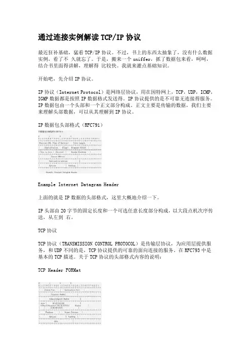
IP数据包头部格式(RFC791)Example Internet Datagram Header上面的就是IP数据的头部格式,这里大概地介绍一下。
IP头部由20字节的固定长度和一个可选任意长度部分构成,以大段点机次序传送,从左到右。
TCP协议TCP协议(TRANSMISSION CONTROL PROTOCOL)是传输层协议,为应用层提供服务,和UDP不同的是,TCP协议提供的可靠的面向连接的服务。
在RFC793中是基本的TCP描述。
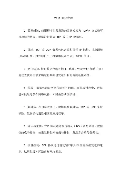
关于TCP协议的头部格式内容的说明:TCP Header FORMatTCP Header FORMat跟IP头部差不多,基本的长度也是20字节。
TCP数据包是包含在一个IP数据报文中的。
好了,简单介绍到此为止。
来看看我捕获的例子吧。
这是一次FTP的连接,呵呵,是cuteftp默认的cuteftp的FTP站点,IP地址是:216.3.226.21。
我的IP地址假设为:192.168.1.1。
下面的数据就是TCO/IP连接过程中的数据传输。
我们可以分析TCP/IP协议数据格式以及TCP/IP连接的三次握手(ThreeWay-Handshake)情况。
下面的这些十六进制数据只是TCP/IP协议的数据,不是完整的网络通讯数据。
第一次,我向FTP站点发送连接请求(我把TCP数据的可选部分去掉了)192.168.1.1->216.3.226.21IP头部: 45 00 00 30 52 52 40 00 80 06 2c 23 c0 a8 01 01 d8 03 e2 15TCP头部:0d 28 00 15 50 5f a9 06 00 00 00 00 70 02 40 00 c0 29 00 00来看看IP头部的数据是些什么。
tcp ip 通讯步骤
1. 数据封装:应用程序将要发送的数据转换为TCP/IP 协议栈可以理解的格式。
数据被封装成TCP 或UDP 数据包。
2. 寻址:TCP 或UDP 数据包包含源和目标IP 地址,以及源和目标端口号。
这些地址用于将数据包路由到正确的目的地。
3. 路由选择:根据数据包的目标IP 地址,网络设备(如路由器)通过查找路由表来确定将数据包发送到目的地的最佳路径。
4. 传输:数据包通过网络传输到目的地。
在传输过程中,数据包可能经过多个网络设备,如路由器和交换机。
5. 解封装:在目标设备上,数据包被解封装,TCP 或UDP 头被移除,数据被传递给相应的应用程序。
6. 确认与重传:TCP 协议通过发送确认(ACK)消息来确认数据包的成功接收。
如果数据包未被成功接收,发送方会重传数据包。
7. 流量控制:TCP 协议通过滑动窗口机制来控制数据发送的速率,以避免缓冲区溢出和网络拥塞。
8. 连接关闭:通信完成后,TCP 连接可以通过发送关闭(FIN)消息来关闭。
TCP-IP详解学习笔记TCP/IP详解学习笔记基本概念为什么会有TCP/IP协议在世界上各地,各种各样的电脑运⾏着各⾃不同的操作系统为⼤家服务,这些电脑在表达同⼀种信息的时候所使⽤的⽅法是千差万别。
就好像圣经中上帝打乱了各地⼈的⼝⾳,让他们⽆法合作⼀样。
计算机使⽤者意识到,计算机只是单兵作战并不会发挥太⼤的作⽤。
只有把它们联合起来,电脑才会发挥出它最⼤的潜⼒。
于是⼈们就想⽅设法的⽤电线把电脑连接到了⼀起。
但是简单的连到⼀起是远远不够的,就好像语⾔不同的两个⼈互相见了⾯,完全不能交流信息。
因⽽他们需要定义⼀些共通的东西来进⾏交流,TCP/IP就是为此⽽⽣。
TCP/IP不是⼀个协议,⽽是⼀个协议族的统称。
⾥⾯包括了IP协议,IMCP协议,TCP协议,以及我们更加熟悉的http、ftp、pop3协议等等。
电脑有了这些,就好像学会了外语⼀样,就可以和其他的计算机终端做⾃由的交流了。
TCP/IP协议分层提到协议分层,我们很容易联想到ISO-OSI的七层协议经典架构,但是TCP/IP协议族的结构则稍有不同。
如图所⽰TCP/IP协议族按照层次由上到下,层层包装。
最上⾯的就是应⽤层了,这⾥⾯有http,ftp,等等我们熟悉的协议。
⽽第⼆层则是传输层,著名的TCP和UDP协议就在这个层次(不要告诉我你没⽤过udp玩星际)。
第三层是⽹络层,IP协议就在这⾥,它负责对数据加上IP 地址和其他的数据(后⾯会讲到)以确定传输的⽬标。
第四层是叫数据链路层,这个层次为待传送的数据加⼊⼀个以太⽹协议头,并进⾏CRC编码,为最后的数据传输做准备。
再往下则是硬件层次了,负责⽹络的传输,这个层次的定义包括⽹线的制式,⽹卡的定义等等(这些我们就不⽤关⼼了,我们也不做⽹卡),所以有些书并不把这个层次放在tcp/ip协议族⾥⾯,因为它⼏乎和tcp/ip协议的编写者没有任何的关系。
发送协议的主机从上⾃下将数据按照协议封装,⽽接收数据的主机则按照协议从得到的数据包解开,最后拿到需要的数据。
tcp ip工作原理TCP/IP是一种网络通信协议,它包括两个独立的协议:TCP (Transmission Control Protocol,传输控制协议)和IP (Internet Protocol,网际协议)。
TCP协议负责将应用层数据分割成小块,称为报文段(segment),并提供可靠的传输机制。
它通过使用序号和确认机制,确保数据按照正确的顺序传输到目标主机。
TCP使用三次握手(three-way handshake)进行连接建立,即发送方先发送一个连接请求报文段,接收方响应一个确认报文段,发送方再发送一个确认报文段,建立了双方之间的连接。
传输完成后,TCP还使用四次挥手(four-way handshake)进行连接的终止。
IP协议则负责将数据报从源主机发送到目标主机。
它使用IP地址标识主机和路由器,将数据报分割成小块(称为数据报),并选择合适的路径进行转发。
每个数据报都包含源IP地址和目标IP地址,以便于路由器可以找到正确的下一个跃点。
当发送方的应用程序需要向目标主机发送数据时,TCP将数据分割成适当大小的报文段,并将它们传递给IP层。
IP层将每个报文段封装在IP数据包中,并添加目标IP地址和源IP地址的头部信息。
这些IP数据包随着目标地址发送到网络中。
在网络中,路由器根据目标IP地址查找下一个跃点,并将IP数据包转发到下一个跃点。
经过多次跃点传输后,IP数据包最终到达目标主机。
在接收方,IP层从网络中接收IP数据包,并解析报文段。
然后,它将这些报文段传递给TCP层。
TCP层根据报文段的序号和确认机制,将它们按照正确的顺序组合成原始数据,然后将数据传递给接收方的应用程序。
通过TCP和IP协议的组合,TCP/IP实现了可靠的端到端通信。
TCP提供了数据的可靠传输,而IP负责将数据从源主机传输到目标主机。
TCP/IP的工作原理保证了数据的完整性和可靠性,使得通信系统非常可靠和稳定。
使用LabVIEW中的TCP/IP和UDP协议前言互联网络协议(IP),用户数据报协议(UDP)和传输控制协议(TCP)是网络通信的基本的工具。
TCP与IP的名称来自于一组最著名的因特网协议中的两个--传输控制协议和互联网络协议。
你能使用TCP/IP来进行单一网络或者互连网络间的通信。
单独的网络会被大的地理距离分隔。
TCP/IP把数据从一个子网网络或者因特网连接的计算机发送到另一个上。
因为TCP/IP 在大多数计算机上是可用的,它能在多样化的系统中间传送信息。
LabVIEW和TCP/IP你能在所有平台上的LabVIEW中使用TCP/IP。
LabVIEW包含了TCP和UDP程序还有能让你建立客户端或者服务器程序的功能。
IPIP执行低层次的计算机间的数据传送。
在组成部分里的IP数据包称为数据报。
一个数据报包含表明来源和目的地地址的数据和报头字。
IP为通过网络或者因特网把数据发送到指定的目的地的数据报确定正确的路径。
IP协议并不能保证发送。
事实上,如果数据报在传输中被复制,IP可能多次传送一个单独的数据报。
所以,程序很少用IP而是用TCP或者UDP代替。
UDPUDP在计算机进程中提供简单而低层次的通信。
进程通过把数据报发送到一个目的地计算机或者端口进行通信。
一个端口是你发送数据的位置。
IP处理计算机对计算机的发送。
在数据报到达目的地计算机后,UDP把数据报移动到其目的端口。
如果目的端口不是开放的,UDP 将删除数据报。
UDP将发生IP的同样的发送问题。
应用程序的UDP的可靠性不强。
例如,一项应用程序能经常把大量信息的数据传送到目的地而丢失少量的数据是肯定的。
在LabVIEW中使用UDP协议因为UDP不是一个TCP似的一个以连接为基础的协议,在你发送或者收到数据之前,你不需要和目的地建立一种连接。
相反,当你每发送一个数据报时,由你指定数据目的地。
操作系统不会报告传输差错使用UDP打开功能在一个端口上打开一个UDP插口。
TCPIP协议详解协议名称:TCP/IP协议详解概述:TCP/IP协议是一种用于互联网通信的网络协议套件,由传输控制协议(TCP)和互联网协议(IP)组成。
它是互联网的基础协议,负责在网络中传输数据,并确保数据的可靠性和完整性。
一、互联网协议(IP):互联网协议(IP)是TCP/IP协议中的网络层协议,主要负责将数据包从源主机传输到目标主机。
它使用IP地址来标识主机和网络,并通过路由选择算法确定数据包的传输路径。
1. IP地址:IP地址是一个32位的二进制数字,通常以点分十进制表示(例如192.168.0.1)。
IP地址分为两个部分:网络地址和主机地址。
网络地址用于标识网络,主机地址用于标识主机。
2. 子网掩码:子网掩码用于将IP地址分为网络地址和主机地址两部分。
它是一个32位的二进制数字,与IP地址进行逻辑与运算,得到网络地址。
3. 路由选择:路由选择是IP协议中的一个重要功能,用于确定数据包的传输路径。
路由选择算法根据网络拓扑和路由表信息,选择最佳的路径将数据包从源主机传输到目标主机。
二、传输控制协议(TCP):传输控制协议(TCP)是TCP/IP协议中的传输层协议,负责在网络中建立可靠的数据传输连接。
1. TCP连接:TCP使用三次握手建立连接,即客户端发送SYN包给服务器,服务器回复SYN-ACK包给客户端,最后客户端发送ACK包给服务器。
这样建立了双方的连接。
2. 可靠性传输:TCP使用序列号和确认应答机制来确保数据的可靠传输。
发送方将数据分割为多个报文段,并为每个报文段分配一个序列号。
接收方通过发送确认应答来确认已接收的报文段,并请求发送方重新发送丢失的报文段。
3. 流量控制:TCP使用滑动窗口机制来进行流量控制。
发送方根据接收方的接收能力调整发送速率,确保不会导致接收方缓冲区溢出。
4. 拥塞控制:TCP使用拥塞窗口机制来进行拥塞控制。
发送方根据网络的拥塞程度调整发送速率,以避免网络拥塞。
tcp ip协议详解TCP/IP协议详解。
TCP/IP协议是互联网的基础,它是一组用于互联网通信的协议集合,包括传输控制协议(TCP)和Internet协议(IP)。
本文将对TCP/IP协议进行详细解析,包括其基本原理、功能特点以及应用场景。
首先,我们来了解一下TCP/IP协议的基本原理。
TCP/IP协议是一种分层的协议体系结构,分为四个层次,网络接口层、网络层、传输层和应用层。
每一层都有特定的功能和责任,通过分层的设计,TCP/IP协议实现了数据的可靠传输和网络通信的高效性。
在网络接口层,TCP/IP协议主要负责数据的物理传输,包括数据的编码、解码、物理介质的传输等。
在网络层,TCP/IP协议则负责数据的路由和转发,通过IP地址对数据进行定位和传输。
传输层是TCP/IP协议的核心层,其中TCP协议负责建立可靠的连接,保证数据的完整性和顺序性,而UDP协议则负责快速传输,适用于实时性要求较高的场景。
最后,应用层则是TCP/IP协议的最上层,包括HTTP、FTP、SMTP等各种应用协议,负责实现特定的应用功能。
其次,我们来探讨一下TCP/IP协议的功能特点。
TCP/IP协议具有以下几个显著的特点,可靠性、灵活性和开放性。
首先,TCP/IP协议通过TCP协议实现了可靠的数据传输,保证了数据的完整性和顺序性,适用于对数据传输要求较高的场景。
其次,TCP/IP协议的灵活性体现在其支持多种网络类型和多种应用协议,可以适应不同的网络环境和应用需求。
最后,TCP/IP协议的开放性体现在其公开的标准和协议,使得各种厂商和组织都可以基于TCP/IP协议进行开发和部署,促进了互联网的快速发展。
最后,我们来看一下TCP/IP协议的应用场景。
TCP/IP协议已经成为互联网通信的标准,广泛应用于各种场景,包括互联网、局域网、广域网等。
在互联网中,TCP/IP协议通过HTTP、FTP、SMTP等应用协议实现了各种网络应用,包括网页浏览、文件传输、电子邮件等。
数据通信常见的网络传输层协议与端口号在当今数字化时代,数据通信无疑是人们生活中不可或缺的一部分。
为了能够高效地进行数据传输,各种网络传输层协议被广泛应用。
本文将介绍一些常见的数据通信网络传输层协议及其对应的端口号。
一、TCP协议与端口号TCP(Transmission Control Protocol)是一种可靠的、面向连接的传输层协议。
它通过建立可靠的连接、提供可靠的数据传输、拥塞控制和流量控制等功能,保证数据在网络中的可靠传输。
1. HTTP(HyperText Transfer Protocol)HTTP是一种在Web浏览器和Web服务器之间进行信息传递的协议。
它使用TCP协议,并默认使用80端口进行通信。
HTTP协议广泛应用于Web浏览器与服务器之间的数据传输,使得用户可以方便地访问各种网站。
2. FTP(File Transfer Protocol)FTP是用于在计算机之间传输文件的协议。
它使用两个端口进行通信,分别是21号端口和20号端口。
21号端口用于发送控制信息,20号端口用于传输文件数据。
FTP协议被广泛应用于文件上传、下载等操作。
3. SMTP(Simple Mail Transfer Protocol)SMTP是用于电子邮件传输的协议。
它使用TCP协议,并默认使用25号端口进行通信。
SMTP协议被用于发送电子邮件,并通过与POP3或IMAP等协议结合,实现电子邮件的收发功能。
4. TelnetTelnet是一种远程登录协议,允许用户通过网络远程登录其他计算机。
它使用TCP协议,并默认使用23号端口进行通信。
Telnet协议已逐渐被SSH(Secure Shell)协议取代,以提供更高的安全性。
二、UDP协议与端口号UDP(User Datagram Protocol)是一种无连接的传输层协议。
它直接将数据包发送到目标主机,无需建立连接,速度较快,但可靠性较差。
1. DNS(Domain Name System)DNS是用于将域名转换为IP地址的协议。
TCP和IP四层协议详解TCP/IP(Transmission Control Protocol/Internet Protocol)的简写,中文译名为传输控制协议/因特网互联协议,又叫网络通讯协议,这个协议是Internet 最基本的协议、Internet国际互联网络的基础,简单地说,就是由网络层的IP 协议和传输层的TCP协议组成的。
定义TCP/IP 是供已连接因特网的计算机进行通信的通信协议。
TCP/IP 指传输控制协议/网际协议 (Transmission Control Protocol / Internet Protocol)。
TCP/IP 定义了电子设备(比如计算机)如何连入因特网,以及数据如何在它们之间传输的标准。
TCP/IP(传输控制协议/网际协议)是互联网中的基本通信语言或协议。
在私网中,它也被用作通信协议。
当你直接网络连接时,你的计算机应提供一个TCP/IP程序的副本,此时接收你所发送的信息的计算机也应有一个TCP/IP程序的副本。
TCP/IP是一个四层的分层体系结构。
高层为传输控制协议,它负责聚集信息或把文件拆分成更小的包。
这些包通过网络传送到接收端的TCP层,接收端的TCP层把包还原为原始文件。
低层是网际协议,它处理每个包的地址部分,使这些包正确的到达目的地。
网络上的网关计算机根据信息的地址来进行路由选择。
即使来自同一文件的分包路由也有可能不同,但最后会在目的地汇合。
TCP/IP使用客户端/服务器模式进行通信。
TCP/IP通信是点对点的,意思是通信是网络中的一台主机与另一台主机之间的。
TCP/IP与上层应用程序之间可以说是“没有国籍的”,因为每个客户请求都被看做是与上一个请求无关的。
正是它们之间的“无国籍的”释放了网络路径,才是每个人都可以连续不断的使用网络。
许多用户熟悉使用TCP/IP协议的高层应用协议。
包括万维网的超文本传输协议(HTTP),文件传输协议(FTP),远程网络访问协议(Telnet)和简单邮件传输协议(SMTP)。
计算机网络TCPIP协议的工作原理与应用计算机网络TCP/IP协议的工作原理与应用计算机网络是指通过计算机互联而形成的网络系统,使得各个计算机之间可以进行数据的传输和共享。
而网络协议则是保证网络中各个计算机之间能够进行有效通信的一种规范。
在计算机网络中,TCP/IP协议是最常用和重要的一种协议,它是互联网中数据传输的核心协议之一。
本文将详细介绍TCP/IP协议的工作原理及其在计算机网络中的应用。
一、TCP/IP协议的工作原理TCP/IP协议是Transmission Control Protocol/Internet Protocol(传输控制协议/网际协议)的简称,由美国国防部在20世纪70年代末初步提出,经过几十年的发展和完善,已成为全球互联网的基本协议标准。
TCP/IP协议栈由四层结构组成,它们分别是应用层、传输层、网络层和链路层。
下面将对这四层逐一介绍:1. 应用层:应用层负责处理具体应用程序与网络之间的通信,在该层中常见的协议有HTTP、FTP等。
这些协议通过TCP或UDP将数据分割成数据包,并添加相关的头部信息,然后通过网络层进一步传输。
2. 传输层:传输层主要负责端到端的可靠数据传输,其中最重要的传输协议是TCP和UDP。
TCP(Transmission Control Protocol)是一种面向连接的可靠传输协议,通过使用三次握手和四次挥手的方式确保数据的可靠交付。
而UDP(User Datagram Protocol)则是一种无连接的不可靠传输协议,通过尽力而为的方式将数据发送给目标机器。
3. 网络层:网络层负责处理网络中的路由和数据包转发,其中最重要的协议是IP(Internet Protocol)协议。
IP协议通过定义一种统一的地址格式,将数据包从源主机传输到目标主机。
在传输过程中,路由器根据目标地址进行数据包的转发,使得数据能够在不同子网络之间进行传输。
4. 链路层:链路层主要负责网络接口之间的数据传输。
TCP/IP协议详解今天看了folder问题,发现对网络知识的了解太匮乏了,所以从别的地方搜点东西,大家一起学习!!![size=3]1、TCP/IP协议栈四层模型TCP/IP这个协议遵守一个四层的模型概念:应用层、传输层、互联层和网络接口层。
网络接口层模型的基层是网络接口层。
负责数据帧的发送和接收,帧是独立的网络信息传输单元。
网络接口层将帧放在网上,或从网上把帧取下来。
互联层互联协议将数据包封装成internet数据报,并运行必要的路由算法。
这里有四个互联协议:网际协议IP:负责在主机和网络之间寻址和路由数据包。
地址解析协议ARP:获得同一物理网络中的硬件主机地址。
网际控制消息协议ICMP:发送消息,并报告有关数据包的传送错误。
互联组管理协议IGMP:被IP主机拿来向本地多路广播路由器报告主机组成员。
传输层传输协议在计算机之间提供通信会话。
传输协议的选择根据数据传输方式而定。
两个传输协议:传输控制协议TCP:为应用程序提供可靠的通信连接。
适合于一次传输大批数据的情况。
并适用于要求得到响应的应用程序。
用户数据报协议UDP:提供了无连接通信,且不对传送包进行可靠的保证。
适合于一次传输小量数据,可靠性则由应用层来负责。
应用层应用程序通过这一层访问网络。
网络接口技术IP使用网络设备接口规范NDIS向网络接口层提交帧。
IP支持广域网和本地网接口技术。
串行线路协议TCP/IPG一般通过internet串行线路协议SLIP或点对点协议PPP在串行线上进行数据传送。
(是不是我们平时把它称之为异步通信,对于要拿LINUX提供建立远程连接的朋友应该多研究一下这方面的知识)?2、ARP要在网络上通信,主机就必须知道对方主机的硬件地址(我们不是老遇到网卡的物理地址嘛)。
地址解析就是将主机IP地址映射为硬件地址的过程。
地址解析协议ARP用于获得在同一物理网络中的主机的硬件地址。
解释本地IP地址(要了解地址解析工作过程的朋友看好了)主机IP地址解析为硬件地址:(1)当一台主机要与别的主机通信时,初始化ARP请求。
tcpip协议详解TCP/IP协议详解。
TCP/IP协议是互联网的基础协议,它是一组用于互联网的通信协议。
TCP/IP协议是由美国国防部高级研究计划局(ARPA)在20世纪70年代末为了建立美国国防部的分散计算机网络而研制的。
TCP/IP协议是一个分层协议,它包括四个层次,网络接口层、网络层、传输层和应用层。
每一层都有自己的功能和协议,它们共同构成了TCP/IP协议栈。
网络接口层是TCP/IP协议的最底层,它负责将数据包发送到网络上的目标地址。
在这一层,数据包被封装成帧,并通过网卡发送到网络上。
常见的网络接口层协议有以太网、Wi-Fi、PPP等。
网络层是TCP/IP协议的第二层,它负责在不同的网络之间传输数据包。
网络层的主要协议是IP协议,它定义了数据包在网络上的传输方式和寻址方式。
IP协议使用IP地址来标识网络上的主机和路由器,通过路由选择算法将数据包从源主机传输到目标主机。
传输层是TCP/IP协议的第三层,它负责在主机之间建立可靠的数据传输连接。
传输层有两个主要协议,TCP和UDP。
TCP协议提供面向连接的、可靠的数据传输服务,它通过三次握手建立连接,通过滑动窗口和确认机制保证数据的可靠传输。
UDP协议提供无连接的、不可靠的数据传输服务,它直接将数据包发送到目标主机,不保证数据的可靠传输。
应用层是TCP/IP协议的最高层,它负责为用户提供各种应用服务。
应用层有许多协议,如HTTP、FTP、SMTP等。
这些协议定义了不同的应用服务,如网页浏览、文件传输、电子邮件等。
总的来说,TCP/IP协议是互联网的基础协议,它提供了一种通用的、灵活的通信方式,使得不同类型的计算机和网络可以互相通信。
通过TCP/IP协议,用户可以方便地访问互联网上的各种资源,实现信息的共享和交流。
在实际应用中,了解TCP/IP协议的工作原理对于网络工程师和系统管理员来说是非常重要的。
只有深入理解TCP/IP协议的各个层次和各个协议,才能更好地设计和管理网络,保证网络的稳定和安全。
tcpip协议是什么TCP/IP协议是什么。
TCP/IP协议是一种网络通信协议,它是互联网的基础,也是许多局域网和广域网所采用的标准协议。
TCP/IP协议是由美国国防部高级研究计划局(ARPA)于上世纪60年代末为了建立分散式网络而研制的一种协议。
TCP/IP协议簇是Internet最基本的协议,它是Internet的基础,因此也被称为Internet协议簇。
TCP/IP协议是指传输控制协议(TCP)和Internet协议(IP)的组合。
TCP/IP协议是一种面向连接的、可靠的、基于数据流的传输层协议,它负责在网络中传输数据。
而IP协议则是一种网络层协议,它负责在网络中寻址和路由数据包。
TCP/IP协议的设计目标是实现可靠的数据传输和全球互联的网络通信。
TCP/IP协议的核心是分层结构,它将网络通信分为四个层次,网络接口层、网络层、传输层和应用层。
在网络接口层,数据通过物理介质(如以太网、无线网等)传输;在网络层,数据通过IP地址进行寻址和路由;在传输层,数据通过端口号进行传输和接收;在应用层,数据通过各种应用程序进行处理和展示。
这种分层结构使得TCP/IP协议更易于实现、维护和扩展。
TCP/IP协议的特点包括开放性、灵活性、可靠性和可扩展性。
开放性意味着TCP/IP协议是公开的标准,任何人都可以使用和实现它;灵活性意味着TCP/IP协议可以适应不同的网络环境和需求;可靠性意味着TCP/IP协议可以保证数据的可靠传输;可扩展性意味着TCP/IP协议可以随着网络规模的增长而扩展。
TCP/IP协议在互联网的发展中起到了至关重要的作用。
它为互联网的建设和发展提供了技术支持,使得不同的网络能够互联互通。
同时,TCP/IP协议也为各种网络应用提供了基础,包括Web浏览、电子邮件、文件传输等。
可以说,没有TCP/IP协议,就没有今天的互联网。
在今天的网络环境中,TCP/IP协议仍然是最为重要的网络通信协议。
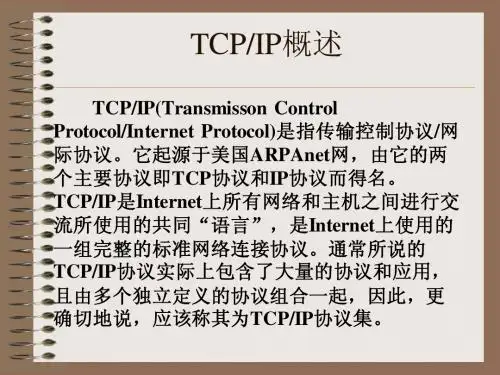
关于关于网络协议和工作原理tcp/ipTCP/IP协议(Transmission Control Protocol/Internet Protocol)叫做传输控制/网际协议,又叫网络通讯协议,这个协议是Internet国际互联网络的基础。
TCP/IP是用于计算机通信的一组协议,我们通常称它为TCP/IP协议族。
它是70年代中期美国国防部为其ARPANET广域网开发的网络体系结构和协议标准,以它为基础组建的INTERNET是目前国际上规模最大的计算机网络,正因为INTERNET的广泛使用,使得TCP/IP 成了事实上的标准。
TCP/IP是网络中使用的基本的通信协议。
虽然从名字上看TCP/IP包括两个协议,传输控制协议(TCP)和网际协议(IP),但TCP/IP实际上是一组协议,它包括TCP、IP、UDP、ICMP、RIP、TELNET、FTP、SMTP、ARP、TFTP等许多协议,这些协议一起称为TCP/IP协议。
TCP/IP由四个层次组成:数据链路层、网络层、传输层、应用层。
一数据链路层这是TCP/IP软件的最低层,负责接收IP数据报并通过网络发送之,或者从网络上接收物理帧,抽出IP数据报,交给IP层。
二网络层负责相邻计算机之间的通信。
其功能包括三方面:1、处理来自传输层的分组发送请求,收到请求后,将分组装入IP数据报,填充报头,选择去往信宿机的路径,然后将数据报发往适当的网络接口。
2、处理输入数据报:首先检查其合法性,然后进行寻径--假如该数据报已到达信宿机,则去掉报头,将剩下部分交给适当的传输协议;假如该数据报尚未到达信宿,则转发该数据报。
3、处理路径、流控、拥塞等问题。
三传输层提供应用程序间的通信。
其功能包括:1、格式化信息流;2、提供可靠传输。
为实现后者,传输层协议规定接收端必须发回确认,并且假如分组丢失,必须重新发送。
四应用层向用户提供一组常用的应用程序,比如电子邮件、文件传输访问、远程登录等。
ip通信流程基本概念IP通信是基于互联网协议(IP,Internet Protocol)的网络通信方式,它是一种在网络上进行数据交换的基本协议。
以下是IP通信的基本概念和流程:IP地址:每个参与网络通信的设备都被分配一个唯一的IP地址,用于在网络中标识和寻址。
IP地址分为IPv4和IPv6两种版本,通常表示为点分十进制(IPv4)或冒号分十六进制(IPv6)。
数据包:数据在网络上传输时被划分为小的单元,称为数据包(Packet)。
每个数据包包含了目标设备的IP地址、源设备的IP地址以及一部分数据。
这些数据包通过网络传输。
路由:在网络中,数据包需要通过路由器进行转发。
路由器根据数据包中的目标IP地址,选择合适的路径将数据包传递到目标设备所在的网络。
DNS解析:当设备通过域名访问其他设备时,需要进行域名解析(DNS,Domain Name System)。
DNS将域名解析为目标设备的IP 地址,使得设备能够正确地寻址目标。
协议栈: IP通信通常涉及多个网络协议,它们构成了协议栈。
常见的协议栈包括TCP/IP协议栈,其中TCP(Transmission Control Protocol)负责可靠的数据传输,而IP负责数据包的路由。
TCP连接:在IP通信中,常使用TCP协议建立连接。
TCP提供了面向连接的、可靠的数据传输,通过三次握手建立连接,确保数据的有序、完整传输。
UDP协议:除了TCP,还有UDP(User Datagram Protocol)。
UDP是一种无连接的协议,适用于一些对数据传输实时性要求较高、允许丢失一些数据的场景。
端口:在TCP/IP通信中,端口用于标识一个应用程序或服务。
源设备和目标设备通过IP地址和端口号确定数据包的发送和接收方。
NAT(网络地址转换): NAT是一种常见的网络技术,它允许多个设备通过单一的公共IP地址访问互联网。
NAT将内部设备的私有IP地址映射到路由器上的公共IP地址。
TCP-IP中的协议中英文总结:ISO:(International Organization for Standardization)国际标准化组织OSI:(Open System Interconnection)开放式系统互联CSMA/CD:(Carrier Sense Multiple Access with Collision Detection)即带冲突检测的载波监听多路访问技术(载波监听多点接入/碰撞检测) CSMA/CA:(Carrier Sense Multiple Access with Collision Avoidance)载波侦听多路访问/冲突避免物理层:无数据链路层:无网络层:IP : (Internet Protocol)网际协议ICMP :(Internet Control Message Protocol),Internet控制报文协议IGMP:(Internet Group Management Protocol ), Internet 组管理协议ARP:(Address Resolution Protocol),地址解析协议RARP:(Reverse Address Resolution Protocol),反向地址解析协议运输层:TCP:(Transmission Control Protocol ),传输控制协议UDP:(User Datagram Protocol),用户数据报协议,SCTP:(Stream Control Transmission Protocol),流量控制传输协议应用层:HTTP:(HyperText Transfer Protocol),超文本传输协议FTP:(File Transfer Protocol),文件传输协议SMTP:(Simple Mail Transfer Protocol),简单邮件传输协议SNMP:(Simple Network Management Protocol ),简单网络管理协议SIP:(Session Initiation Protocol),会话初始协议SSH:(Secure Shell Protocol),安全外壳协议DNS:(Domain Name System)网络名称系统DHCP:(Dynamic Host Configuration Protocol)动态主机設定協定。
Journal of High Speed Networks13(2004)169–182169 IOS PressA detailed performance analysis of UDP/IP, TCP/IP,and M-VIA network protocols using Linux/SimOS1Chulho Won a,Ben Lee a,Chansu Yu b,Sangman Moh c,Kyoung Park d and Myung-Joon Kim da School of Electrical Engineering and Computer Science,Oregon State UniversityE-mail:{chulho,benl}@b Department of Electrical and Computer Engineering,Cleveland State UniversityE-mail:c.yu91@c School of Internet Engineering,Chosun University,Gwangju,KoreaE-mail:smmoh@chosun.ac.krd Internet Server Group,Digital Home Research Division,Electronics and Telecommunications Research Institute (ETRI),Daejeon,KoreaE-mail:{kyoung,joonkim}@etri.re.krAbstract.This paper presents a performance study of UDP/IP,TCP/IP,and M-VIA using Linux/SimOS.Linux/SimOS is a Linux operating system port to a complete machine simulator SimOS.A complete machine simulator includes all the system components,such as CPU,memory, I/O devices,etc.,and models them in sufficient detail to run an operating system.Therefore,a real program execution environment can be set up on the simulator to perform detailed system evaluation in a non-intrusive manner.The motivation for Linux/SimOS is to alleviate the limitations of SimOS(and its variants),which only support proprietary operating systems.Therefore,the availability of the popular Linux operating system for a complete machine simulator will make it an extremely effective andflexible simulation environment for studying all aspects of computer system performance,especially evaluating communication protocols and network interfaces.The contributions made in this paper are two-fold: First,the major modifications that were necessary to run Linux on SimOS are described.These modifications are specific to SimOS I/O device models and thus any future operating system porting efforts to SimOS will experience similar challenges.Second,a detailed analysis of UDP/IP, TCP/IP,and M-VIA is performed to demonstrate the capabilities of Linux/SimOS.The simulation study shows that Linux/SimOS is capable of capturing all aspects communication performance,including the effects of the kernel,device driver,and network interface.Keywords:SimOS,complete system simulation,Linux,instruction set simulators,UDP/IP,TCP/IP,M-VIA1.IntroductionThe growing demand for high-performance communication on System Area Networks(SANs)has led to signif-icant research efforts towards low-latency communication protocols,such as Virtual Interface Architecture(VIA) [10]and InfiniBand Architecture(IBA)[11].Before these protocols can become established,they need to be ac-curately evaluated to understand how they perform and identify key bottlenecks.However,detailed performance analysis of network protocols is often difficult due to their complexity.This is because communication perfor-mance is dependent not only on the processor speed but also on the communication protocols and their interaction with the kernel,device driver,and network interface.Therefore,these interactions must be properly captured to evaluate the protocols and to improve on them.1A shorter version of this paper appears in The2002International Conference on Parallel Processing(ICPP-02),August18–21,Vancouver, BC,2002.0926-6801/04/$17.00 2004–IOS Press and the authors.All rights reserved170 C.Won et al./Analysis of UDP/IP,TCP/IP,and M-VIA network protocols using Linux/SimOSThe evaluation of communication performance has traditionally been done using instrumentation[3],where data collection codes are inserted to a target program to measure the execution time.However,instrumentation has three major disadvantages.First,data collection is limited to the hardware and software components that are visible to the instrumentation code,potentially excluding detailed hardware information or operating system behavior.Second, instrumentation codes interfere with the dynamic system behavior.That is,event occurrences in a communication system are often time-dependent,and the intrusive nature of instrumentation can perturb the system being studied. Third,instrumentation cannot be used to evaluate new features or a system component that does not yet exist. The alternative to instrumentation is to perform simulations[1,4,6,13,14].At the core of these simulation tools is an instruction set simulator capable of tracing the cycle-level interactions between hardware and software.How-ever,they are suitable for evaluating general application programs whose performance depends only on processor speed,not communication speed.That is,these simulators only simulate portions of the system hardware and thus are unable to capture the complete behavior of a communication system.On the other hand,a complete machine simulation environment[2,3]removes these deficiencies.A complete machine simulator includes all the system components,such as CPU,memory,I/O devices,etc.,and models them in sufficient detail to run an operating system.Therefore,a real program execution environment can be set up on the simulator to perform system evaluation in a non-intrusive manner.Another advantage of a complete system simulation is that system evaluations do not depend on the availability of the actual hardware.For example,a new network interface can be prototyped by replacing the existing model with the new model.Based on the aforementioned discussion,this paper presents a performance analysis of network protocols UDP/IP,TCP/IP,and M-VIA using Linux/SimOS.Linux/SimOS is a Linux operating system port to a complete machine simulator SimOS[3].The development of Linux/SimOS was motivated by the fact that the current ver-sion of SimOS only supports the proprietary SGI IRIX operating system.Therefore,the availability of popular Linux operating system for a complete machine simulator will make it an extremely effective andflexible simula-tion environment for studying all aspects of computer system performance,especially evaluating communication protocols and network interfaces.The contributions made in this paper are two-fold:First,the major modifications that were necessary to run Linux on SimOS are described.These modifications are specific to SimOS I/O device models and thus any future operating system porting efforts to SimOS will experience similar challenges.Second, a detailed analysis of UDP/IP,TCP/IP,and M-VIA protocols is performed,which clearly show the advantage of using Linux/SimOS.Linux/SimOS is capable of capturing all aspects communication performance that includes the effects of the kernel,device driver,and network interface.These results help understand how the protocols work,identify key areas of interests,and suggest possible opportunities for improvement not only in the protocol stack but also in terms of hardware support.The rest of the paper is organized as follows.Section2presents the related work.Section3discusses the Linux/SimOS environment and the major modifications that were necessary to port Linux to SimOS.The dis-cussion also includes the changes required to run M-VIA,which is an implementation of the Virtual Interface Architecture for Linux,on Linux/SimOS.Section4presents the simulation study of UDP/IP,TCP/IP,and M-VIA. Section5concludes the paper and discusses some future work.2.Related workThere exist a number of simulation tools that contain detailed models of today’s high-performance microproces-sors[1–4,6,13,14].The SimpleScalar tool set includes a number of instruction-set simulators of varying accu-racy/speed to allow the exploration of microarchitecture design space[6].It was developed to evaluate the perfor-mance of general-purpose application programs that depend on the processor speed.RSIM is an execution-driven simulator developed for studying shared-memory multiprocessors(SMPs)and non-uniform memory architectures (NUMAs)[1].RSIM was developed to evaluate parallel application programs whose performance depends on the processor speed as well as the interconnection network.However,neither simulators support system-level sim-ulation because their focus is on the microarchitecture and/or interconnection network.Instead,system calls areC.Won et al./Analysis of UDP/IP,TCP/IP,and M-VIA network protocols using Linux/SimOS171 supported through a proxy mechanism.Moreover,they do not model system components,such as I/O devices and interrupt mechanism that are needed to run the system software,such as the operating system kernel and hardware drivers.Therefore,these simulators are not appropriate for studying communication performance.SimOS was developed to facilitate computer architecture research and experimental operating system develop-ment[3].It is the most complete simulator for studying computer system performance.There are several mod-ifications being made to SimOS.SimOS-PPC is being developed at IBM Austin Research Laboratory,which models a variety of PowerPC-based systems and microarchitectures[16].There is also a SimOS interface to Sim-pleScalar/PowerPC being developed at UT Austin[17].However,these systems only support AIX as the target operating system.Therefore,it is difficult to perform detailed evaluations without knowing the internals of the kernel.Virtutech’s SimICS[2]was developed with the same purpose in mind as SimOS and supports a number of commercial as well as Linux operating systems.The major advantage of SimICS over SimOS is improved simulation speed using highly optimized codes for fast event handling and a simple processor pipeline.However, SimICS is proprietary and thus the internal details of the simulator are not available to the public.This makes it difficult to add or modify new hardware features.The motivation for Linux/SimOS is to alleviate these restrictions by developing an effective simulation environment for studying all aspects of computer system performance using SimOS with theflexibility and availability of the Linux operating system.3.Overview of Linux/SimOSFigure1shows the structure of Linux/SimOS.An x86-based Linux machine serves as the host for running the simulation environment.SimOS runs as a target machine on the host,which consists of simulated models of CPU, memory,timer,and various I/O devices(such as Disk,Console,and Ethernet NIC).On top of the target machine, Linux kernel version2.3for MIPS runs as the target operating system.3.1.SimOS machine simulatorThis subsection briefly describes the functionality of SimOS,and the memory and I/O device address mapping. For a detail description of SimOS,please refer to[3].SimOS supports two execution-driven,cycle-accurate CPU models:Mipsy and MSX.Mipsy models a simple pipeline similar to MIPS R4000,while MSX models a superscalar,dynamically scheduled pipeline similar to MIPSFig.1.The structure of Linux/SimOS.172 C.Won et al./Analysis of UDP/IP,TCP/IP,and M-VIA network protocols using Linux/SimOSR10000.The CPU models support the execution of the MIPS instruction set[12].SimOS also models a memory management unit(MMU),including the related exceptions.Therefore,the virtual memory translations occur as in a real machine.SimOS also models the behavior of I/O devices by performing DMA operations to/from the memory and interrupting the CPU when I/O requests complete.It also supports the simulation of a multiprocessor system with a bused-based cache-coherent memory system or a Cache-Coherent Non-uniform Memory Architecture(CC-NUMA)system.Figure2represents the SimOS memory and I/O device address mapping.The virtual address space is subdivided into four segments.Segments kseg0through kseg2can only be accessed in the kernel mode,while segment kuseg can be accessed either in user or kernel mode.The kernel executable code is contained in kseg0and mapped directly to the lower512Mbytes of the physical memory.The segments kuseg and kseg2,which contain user process and per process kernel data structures,respectively,are mapped to the remaining address space in the physical memory.Therefore,communication between CPU and main memory involves simply reading and writing to the allocated memory.On the other hand,I/O device addresses are mapped to the uncached kseg1segment,and a hash table called the device registry controls its access.The function of the device registry is to translate an I/O device register access to the appropriate I/O device simulation routine.Therefore,each I/O device has to first register its device registers with the device registry,which maps an appropriate device simulator routine at a location in the I/O address space.This is shown in Table1.In response to device driver requests,I/O device models provide I/O services and interrupt the CPU as appropriate.SimOS provides several I/O device models,which includes console,SCSI disk,Ethernet NIC,and timer.These devices provide the interface between the simulator and the real world.The console model allows a user to readFig.2.Address mapping mechanism in SimOS.Table1I/O device address mappingDevice Start address Size in bytesTimer0xA0E000004Console0xA0E010008Ethernet NIC0xA0E020002852Disk0xA0E10000542208C.Won et al./Analysis of UDP/IP,TCP/IP,and M-VIA network protocols using Linux/SimOS173 messages from and type in commands to the simulated machine.The SimOS NIC model enables a simulated machine to communicate with other simulated machines or real machines through the Ethernet.By allocating an IP address for the simulated machine,it can act as an Internet node,such as a Web browser or a Web server.SimOS uses the host machine’sfile system to provide the functionality of a hard disk,maintaining the disk’s contents in afile on the host machine.Reads and writes to the simulated disk become reads and writes to thisfile,and DMA transfers require simply copying data from thefile into the portion of the simulator’s address space representing the target machine’s main memory.3.2.Linux/SimOS interfaceIn this subsection,the major modifications that were necessary to port Linux to SimOS are discussed,i.e., Linux/SimOS interface.Most of the major modifications were done on the I/O device drivers for Linux.Therefore, the description will focus on the interfacing requirements between Linux hardware drivers and SimOS I/O device modules.3.2.1.Timer and consoleSimOS implements a simple real-time clock that indicates the current time as the number of seconds that have elapsed since January1,1970.The real-time clock keeps the time value in a32-bit register located at address 0xA0E00000(see Table1).A user program reads the current time using the gettimeofday()system call.The Linux timer driver was modified to reflect the simplicity of the SimOS timer model.The SimOS real-time clock has a single register,while a timer chip in a real system has tens of registers that are accessed by the driver.Also,the Linux timer driver periodically adjusts the real-time clock to prevent it from drifting due to temperature or system powerfluctuation.Since these problems are not present in a simulation environment,these features were removed to simplify debugging.Console is used as a primary interface between the simulated machine and the external world.Linux commands are entered through the console,and the command execution results are printed on the console.A sample console output with Linux boot message is shown in Fig.3.Fig.3.Linux/SimOS console output with Linux boot message.174 C.Won et al./Analysis of UDP/IP,TCP/IP,and M-VIA network protocols using Linux/SimOS3.2.2.SCSI diskThe SimOS disk model simulates a SCSI disk,which has the combined functionality of a SCSI adapter,a DMA, a disk controller,and a disk unit.Therefore,the registers in the SimOS disk model represent a combination of SCSI adapter registers,DMA descriptors,and disk status and control registers.This is different from a real SCSI disk, which implements them separately,and thus how the Linux disk driver views the disk.In particular,the problem arises when application programs make disk requests.These requests are made to the SCSI adapter with disk unit numbers,which are then translated by the disk driver to appropriate disk register addresses.But,the SimOS disk model performs the translation internally and thus the Linux disk driver is incompatible with the SimOS disk model.Therefore,the SimOS disk model had to be completely rewritten to reflect how the Linux disk driver communicates with the SCSI adapter and the disk unit.3.2.3.Kernel bootloaderWhen the kernel and the device drivers are prepared and compiled,a kernel executable is generated in ELF binary format[15].It is then the responsibility of the SimOS bootloader to load the kernel executable into the main memory of the simulated machine.When the bootloader starts,it reads and looks for headers in the executablefile.An ELF executable contains three different type headers:afile name header,program headers,and section headers.Each program header is associated with a program segment,which holds a portion of the kernel code.Each program segment has a number of sections,and a section header defines how these sections are loaded into memory.Therefore,the bootloader has to use both program and section headers to properly load the program segment.Unfortunately,the bootloader that came with the SimOS distribution was incomplete and thus did not properly handle the ELF format.That is,it did not use both program and section headers to load the program.Therefore,the bootloader was modified to correct this problem.3.2.4.Ethernet NICThe SimOS Ethernet NIC model supports connectivity to simulated hosts as well as to real hosts.The Ethernet NIC model is controlled by a set of registers mapped into the memory region starting at0xA0E02000(see Table1). The data transfer between the simulated main memory and NIC occurs via DMA operations using descriptors pointing to DMA buffers.Typically,the Linux NIC driver allocates DMA buffers in the uncached kseg1segment. Since the device registry controls this memory region in SimOS,two modifications were necessary to differentiate between I/O device accesses and uncached memory accesses.First,the Linux Ethernet driver was changed to allocate DMA buffers using the device registry.Second,the device registry was modified to handle the allocated DMA buffer space as an uncached memory space.Network simulation in SimOS can be performed using a separate simulator called EtherSim[3].The main function of EtherSim is to forward the received packets to the destination host.Although EtherSim is not directly related to the Linux/SimOS interface,its functionality and the modifications that were made to facilitate network simulation with Linux/SimOS are briefly discussed.EtherSim basically takes care of the activities of sending simulated Ethernet frames and receiving IP packets on behalf of SimOS(i.e.,a simulated host).EtherSim can be configured to have any number of real and simulated hosts.A simulated host communicating with another host via EtherSim is shown in Fig.4.EtherSim maintains the address information of the simulated host(s),which includes the IP and Ethernet addresses as well the socket address of the simulated NIC.A simulated host sends a simulated Ethernet frame to EtherSim using UDP.EtherSim then extracts the IP packet from the simulated Ethernet frame and forwards it to the destination host.In the case of a receive,EtherSim captures IP packets destined for one of the simulated hosts by running its host’s Ethernet interface in promiscuous mode.It then forms a UDP packet from the captured packet and forwards it to the simulate host.Some modifications were necessary to run EtherSim on a host running Linux operating system.The modifica-tions made were mainly to improve portability.The original EtherSim that comes with the SimOS source distrib-ution was written for Sun Solaris operating system,and could not be ported directly to Linux.Therefore,several of the Solaris operating system specific network library calls were replaced with libpcap[9]and libnet[8],which are standard libraries related to network packet capturing.As a result,the modified version of EtherSim can run on any Linux host,even on the same host running Linux/SimOS.C.Won et al./Analysis of UDP/IP,TCP/IP,and M-VIA network protocols using Linux/SimOS175munication between a simulated host and a real host using EtherSim.4.Simulation study of UDP/IP,TCP/IP,and M-VIAThis section presents the performance measurements of UDP/IP,TCP/IP,and M-VIA[12]to demonstrate the ca-pabilities of Linux/SimOS.The measurements were performed in a simulation set-up where Linux/SimOS is used to model two host machines connected through a network.To evaluate the performance of these three protocols, test programs were run on Linux/SimOS that accepts command-line options specifying send/receive,a message size,and address.UDP and TCP/IP performance was measured by having a client program send/receive a mes-sage to/from a server program.On the other hand,vpingpong was used to evaluate the performance of M-VIA. vpingpong employs a number of library functions provided by VIP Provider Library to initiate message transfers on M-VIA.The program has two modes of operation,send and receive,which are selectable with a command-line option.When vpingpong starts,a given number of messages are exchanged between a sender and a receiver.The vpingpong program is one of the test programs included in the M-VIA1.2b2source code distribution[12].4.1.Simulation environmentThe CPU model employed was Mipsy with32Kbyte L1instruction and data caches with1-cycle hit latency,and 1Mbyte L2cache with10-cycle hit latency.The main memory was configured to have32Mbyte with hit latency of100cycles,and DMA on the Ethernet NIC model was set to have a transfer rate of1200Mbytes/sec.The results were obtained using SimOS’s data collection mechanism,which uses a set of annotation routines written in Tcl[18].These annotations are attached to specific events of interest,and when an event occurs the associated Tcl code is executed.Annotation codes have access to the entire state of the simulated system,and more importantly, data collection is performed in a non-intrusive manner.The performance of UDP and TCP/IP was evaluated by directly sending messages through the legacy protocol stack in Linux/SimOS.On the other hand,M-VIA consists of three components:VI provider library(vipl)is a collection of library calls to obtain VI services;M-VIA kernel module(vipk_core)contains a set of modularized kernel functions implemented in user-level;and M-VIA device drivers(vipk_dev)provide an interface to NIC. Some modifications were necessary to run M-VIA on Linux/SimOS.First,because M-VIA was released only for x86-based Linux hosts,some of the source codes had to be modified to run them on Linux/SimOS.In particular, the code for fast traps(vipk_core/vipk_ftrap.S)had to be rewritten because the MIPS system supports a different system call convention than x86-based systems.Second,the driver for M-VIA had to be modified(similar to the discussion in Subsection3.2)to work with SimOS Ethernet NIC.176 C.Won et al./Analysis of UDP/IP,TCP/IP,and M-VIA network protocols using Linux/SimOSFig.5.Message send/receive latencies.4.2.Overall performanceThe performance study focused on the latency(in cycles)to perform send/receive.These simulations were run with afixed MTU(Maximum Transmission Unit)size of1,500bytes with varying message sizes.The total cycle times required to perform send/receive as a function of message size are shown in Fig.5.The send results are based on the number of clock cycles required to perform sendto()for UDP,send()for TCP,or VipPostSend() for M-VIA.The receive results are based on the time between the arrival of a message and when recvfrom()for UDP,recv()for TCP,or VipPostRecv()for M-VIA returns.These results represent only the latency measurement of major operations directly related to sending and receiving messages and do not include the time needed to set up socket communication for UDP and TCP,and memory registration for M-VIA.These results also do not include the effects of MAC and physical layer operations.The results in Fig.5clearly show the advantage of using low-latency,user-level messaging,especially for small messages.For message sizes less than MTU,the improvement factors for M-VIA send/receive latencies over UDP and TCP/IP are2.2∼2.6/1.6∼3.1and3.1∼3.3/2.3∼4.9,respectively.For message sizes greater than MTU,the improvement factors for M-VIA send/receive latencies over UDP and TCP/IP are2.8/1.4∼2and3.1∼3.3/1.4∼2, respectively.yer-level performanceThe latencies for UDP/IP,TCP/IP,and M-VIA send/receive were then divided based on the various layers avail-able for each protocol.This allows us to observe how much time is spent on each layer and how each layer contributes to thefinal result.The latencies for UDP and TCP/IP were broken into layers associated with APPL, UDP/TCP,IP,DEV,and DMA.APPL includes the time required to perform socket operations sendto()/recvfrom() and send()/recv()for UDP and TCP,respectively.UDP/TCP and IP are the times for executing UDP/TCP and IP protocols,respectively.DEV represents the device driver and includes all the operations between IP and host-side DMA,including DMA interrupt handling.Finally,DMA represents the time to DMA data between host memory and NIC buffers.Similarly,the latencies for M-VIA were broken into layers associated with APPL,TRANS,DEV,and DMA. APPL represents the time required to initiate VI provider library functions VipPostSend()and VipPostRecv()(andC.Won et al./Analysis of UDP/IP,TCP/IP,and M-VIA network protocols using Linux/SimOS177Fig.6.Send latency.VipRecvWait()).This involves creating a descriptor in the registered memory and then adding the descriptor to the send/receive queue.The transport layer then performs virtual-to-physical/physical-to-virtual address translation and fragmentation/de-fragmentation.Therefore,TRANS represents the time spent on the transport layer,but also includes part of the device driver,mainly DMA setup.This is because the M-VIA implementation does not separate the two layers for optimization purposes.Thus,DEV includes only the DMA interrupt handling time.Again,DMA represents the time to DMA data between host memory and NIC buffers.The results of send and receive latencies are summarized in Figs6and7,respectively,where each message size has three bar graphs for M-VIA(left),UDP/IP(middle),and TCP/IP(right).The results are also presented in a tabular form in Table2.The maximum message size in Table2is32Kbytes due to the fact that M-VIA’s data buffer size was limited to32Kbytes.Also,32-Kbyte results were not included in Figs6and7since they would overshadow the other results.Figure6shows the send latencies.For UDP/IP,APPL and UDP are small and remain relatively constant.How-ever,IP and DEV dominate as the message size grows.In particular,for message size greater than MTU,IP increases significantly as a function of messages size.This is because IP handles packet fragmentation,data copying from user space to socket buffer,and checksumming.In addition,DMA also takes a significant portion of the latency for message sizes over4Kbytes.For TCP/IP send,TCP constitutes the largest portion of the overall execution time.This is because the TCP layer performs the most of time-consuming operations,which include packet de-fragmentation,data copying from socket to user buffers,checksumming,ACK reception,andflow control.Note that there is no congestion control since packet losses were not simulated.Moreover,TCP dominates while IP represents only a small portion of the overall execution time.This is because,unlike UDP,packet fragmentation and data copying from user space are performed at the TCP layer.Thus,IP has minimal effect on the overall per-formance of TCP/IP,while it is the direct opposite for UDP/IP.For M-VIA send,latencies are relatively evenly spread among APPL,TRANS,and DEV for message size up to1Kbyte.However,as message size increases beyond 1Kbytes,DMA takes up most of the latency and increases rapidly.TRANS and DEV also increase significantly for message sizes larger than1Kbytes due to fragmentation and interrupt handling,respectively.Figure7shows the receive latencies.When messages are larger than MTU,all the UDP/IP layers,except APPL, increase rapidly.Among them,UDP and IP increases are most noticeable.The increase in IP is caused by de-。