怎样配置在三层交换的VLAN间路由(en)
- 格式:pdf
- 大小:27.65 KB
- 文档页数:8

实训6 用三层交换机实现VLAN间路由一、实训目的1.了解VLAN间路由的意义2.掌握使用三层交换机实现vlan间路由的解决方法3.模拟并解决小型企业或分公司的VLAN间路由问题二、实训逻辑图图6-1 实训逻辑图三、实训内容及步骤1.进入交换机(先不要按逻辑图连接交换机),查看是否已有Vlan配置(1)查看Vlan配置(show vlan brief)(2)查看Vtp状态(show vtp status)(3)若Vtp模式不是Server,请将其改为Server(vtp mode server)(4)删除默认Vlan以外的所有Vlan信息(no vlan vlan_id)(5)查看所有端口是否都在Vlan 1下(show vlan brief)(6)若有端口不是Vlan 1下,请将其加入到Vlan 1下做完以上步骤后,再查看一次Vlan信息,检查是否所有端口已绑定在Vlan 1下,并且没有其他Vlan设置;若仍有端口没有处于Vlan 1下,或有其他Vlan信息,请重复以上项目,否则可能影响下面的实训数据。
2.创建Vlan并将端口绑定到VlanSW2950# vlan dataSW2950 (vlan)# vlan 2 name v2SW2950 (vlan)# vlan 3 name v3SW2950 (config) # int f0/3SW2950 (config-if) # switchport mode accessSW2950 (config-if) # switchport access vlan 2SW2950 (config) # int f0/4SW2950 (config-if) # switchport mode accessSW2950 (config-if) # switchport access vlan 3SW2950 (config-if) #endSW2950#show vlan briefVLAN Name Status Ports---- -------------------------------- --------- -------------------------------1 default active Fa0/1, Fa0/2, Fa0/5, Fa0/6,Fa0/7,Fa0/8, Fa0/9, Fa0/10,Fa0/11,Fa0/12, Fa0/13, Fa0/14, Fa0/15, Fa0/16, Fa0/17, Fa0/18,Fa0/19, Fa0/20, Fa0/21, Fa0/22,Fa0/23, Fa0/24, Gig1/1, Gig1/22 v2 active Fa0/33 v3 active Fa0/43.将F0/24端口设定为中继端口SW2950 (config) # int f0/24SW2950 (config-if) # switchport mode trunkSW3550 (config) # int f0/24SW3550 (config-if) # switchport trunk encapsulation dot1qSW3550 (config-if) # switchport mode trunkSW3550#show int trunkPort Mode Encapsulation Status Native vlanFa0/24 on 802.1q trunking 1Port Vlans allowed on trunkFa0/24 1-1005Port Vlans allowed and active in management domainFa0/24 1,2,3Port Vlans in spanning tree forwarding state and not prunedFa0/24 1,2,3若两台交换机上的F0/24端口模式“mode”都为“on”,表明Trunk状态已正常工作。

教你利⽤三层交换机实现VLAN间路由本⽂档详细介绍利⽤三层交换机实现 VLAN 间路由,⽂内含长段代码可复制可往左滑,希望对⼤家有帮助!实验背景某企业有两个主要部门,技术部和销售部,分处于不同的办公室,为了安全和便于管理对两个部门的主机进⾏了 VLAN 的划分,技术部和销售部分处于不同的VLAN,先由于业务的需求需要销售部和技术部的主机能够相互访问,获得相应的资源,两个部门的交换机通过⼀台三层交换机进⾏了连接。
技术原理三层交换机具备⽹络层的功能,实现 VLAN 相互访问的原理是:利⽤三层交换机的路由功能,通过识别数据包的 IP 地址,查找路由表进⾏选路转发,三层交换机利⽤直连路由可以实现不同 VLAN 之间的相互访问。
三层交换机给接⼝配置 IP 地址。
采⽤ SVI(交换虚拟接⼝)的⽅式实现 VLAN 间互连。
SVI 是指为交换机中的VLAN 创建虚拟接⼝,并且配置 IP 地址。
Tag VLAN是基于交换机端⼝的⼀种类型,主要⽤于使交换机的相同Vlan内的主机之间可以直接访问,同时对于不同Vlan的主机进⾏隔离。
trunk主要⽤在连接其它交换机,以便在线路上承载多个vlanWLAN是Wireless Local Area Network的简称,指应⽤⽆线通信技术将计算机设备互联起来,构成可以互相通信和实现资源共享的⽹络体系。
802.1x协议是WLAN第⼆代的认证技术,它是基于客户端-服务器(Client-Server)结构的访问控制和认证协议。
它可以限制未经授权的⽤户/设备通过接⼊端⼝(Access Port)访问LAN/WLAN。
DOT1Q是提供VLAN识别和服务质量(QoS)级别的IEEE标准。
电⽓和电⼦⼯程师协会(IEEE,全称是Institute of Electrical and Electronics Engineers)是⼀个美国的电⼦技术与信息科学⼯程师的协会,是世界上最⼤的⾮营利性专业技术学会。

VLAN间路由配置步骤详解在进行VLAN间路由配置之前,需要确保以下几个条件满足:1. 确认设备支持VLAN功能:路由器、交换机和防火墙等网络设备需要支持VLAN功能才能进行VLAN间路由配置。
2. 确定VLAN划分范围:根据网络拓扑和需求,确定所需的VLAN 划分范围,例如将不同部门或不同楼层划分到不同的VLAN中。
3. 分配IP地址:每个VLAN需要分配一个唯一的IP子网地址,确保不同VLAN之间的IP地址不冲突。
一旦以上条件都满足,我们可以按照以下步骤进行VLAN间路由配置:1. 配置VLAN:在交换机上配置VLAN,并进行端口划分。
首先,登录到交换机的控制台或Web界面,创建VLAN并为之分配一个唯一的VLAN ID。
然后,根据需要将不同端口加入到对应的VLAN中。
2. 配置子接口:在路由器上配置VLAN间路由的子接口。
登录路由器的控制台或Web界面,为每个VLAN创建一个子接口,并将其与对应的VLAN关联起来。
为每个子接口配置IP地址,确保各个子接口之间的IP地址不冲突。
3. 配置路由:为了实现不同VLAN之间的通信,需要在路由器上进行路由配置。
根据网络拓扑和需求,配置静态路由或动态路由协议来实现VLAN间的路由。
4. 配置安全策略:为了增强网络安全性,可以在防火墙或路由器上配置安全策略,如访问控制列表(ACL)或虚拟专用网(VPN)等,限制不同VLAN之间的通信或保护敏感数据。
5. 测试与验证:完成以上配置后,需要进行测试和验证。
通过跨VLAN的主机之间进行互相ping命令测试,确保VLAN间路由配置成功。
必要时,可以进行抓包等工具的使用,检查数据包的转发情况。
总结起来,VLAN间路由配置涉及交换机、路由器和安全设备等的设置和配合。
通过合理划分VLAN、配置子接口、设置路由和安全策略,并进行有效的测试与验证,可以实现不同VLAN之间的通信和互联,提高网络的灵活性和安全性。

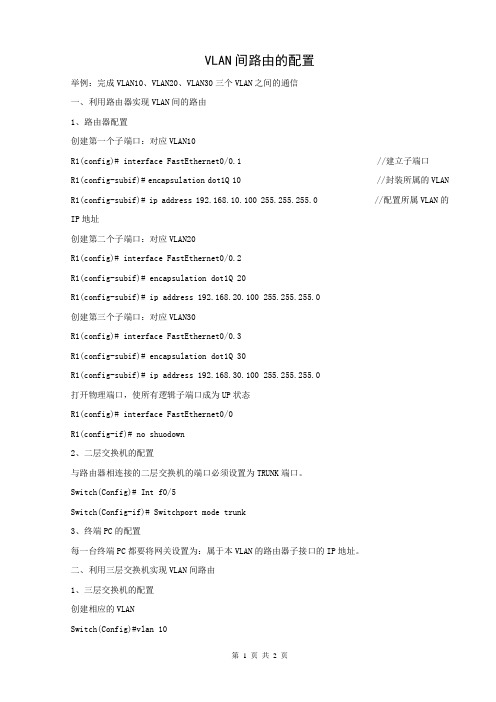
VLAN间路由的配置举例:完成VLAN10、VLAN20、VLAN30三个VLAN之间的通信一、利用路由器实现VLAN间的路由1、路由器配置创建第一个子端口:对应VLAN10R1(config)# interface FastEthernet0/0.1 //建立子端口R1(config-subif)# encapsulation dot1Q 10 //封装所属的VLAN R1(config-subif)# ip address 192.168.10.100 255.255.255.0 //配置所属VLAN的IP地址创建第二个子端口:对应VLAN20R1(config)# interface FastEthernet0/0.2R1(config-subif)# encapsulation dot1Q 20R1(config-subif)# ip address 192.168.20.100 255.255.255.0创建第三个子端口:对应VLAN30R1(config)# interface FastEthernet0/0.3R1(config-subif)# encapsulation dot1Q 30R1(config-subif)# ip address 192.168.30.100 255.255.255.0打开物理端口,使所有逻辑子端口成为UP状态R1(config)# interface FastEthernet0/0R1(config-if)# no shuodown2、二层交换机的配置与路由器相连接的二层交换机的端口必须设置为TRUNK端口。
Switch(Config)# Int f0/5Switch(Config-if)# Switchport mode trunk3、终端PC的配置每一台终端PC都要将网关设置为:属于本VLAN的路由器子接口的IP地址。
二、利用三层交换机实现VLAN间路由1、三层交换机的配置创建相应的VLANSwitch(Config)#vlan 10Switch(Config)#vlan 20Switch(Config)#vlan 30创建VLAN接口并设置IP地址;Switch(Config)#interface vlan 10Switch(Config-If-Vlan10)#ip address 192.168.10.100 255.255.255.0Switch(Config)#interface vlan 20Switch(Config-If-Vlan20)#ip address 192.168.20.100 255.255.255.0Switch(Config)#interface vlan 30Switch(Config-If-Vlan30)#ip address 192.168.30.100 255.255.255.0设置TRUNK端口与二层交换机相连接的三层交换机的端口必须设置为TRUNK端口。


三层交换机怎么设置VLAN间路由方法步骤1、首先打开思科模拟器软件,找出一台三层交换机和两台PC2、将三层交换机和两台PC用直通线连接起来3、在三层交换机上划分VLAN,命令是:复制内容到剪贴板Switch#conf tEnter configuration commands, one per line. End with CNTL/Z.Switch(config)#vlan 2Switch(config-vlan)#exitSwitch(config)#intf0/5Switch(config-if)#switchport mode access Switch(config-if)#switchport access vlan 1Switch(config-if)#int f0/6Switch(config-if)#switchport mode access Switch(config-if)#switchport access vlan 24、开启三层交换机的三层交换路由功能,命令是:ip routing5、给PC配置IP地址和网关6、进入三层交换机里面配置VLAN,命令是:复制内容到剪贴板Switch(config)#int vlan 1Switch(config-if)#noshutSwitch(config-if)#ip add 172.16.10.1 255.255.255.0Switch(config-if)#int vlan 2 Switch(config-if)#no shutSwitch(config-if)#ip add 172.16.20.1 255.255.255.07、利用ping命令对PC之间进行通信测试,可以ping通的结果补充:交换机基本使用方法作为基本核心交换机使用,连接多个有线设备使用:网络结构如下图,基本连接参考上面的【方法/步骤1:基本连接方式】作为网络隔离使用:对于一些功能好的交换机,可以通过模式选择开关选择网络隔离模式,实现网络隔离的作用,可以只允许普通端口和UPlink端口通讯,普通端口之间是相互隔离不可以通讯的除了作为核心交换机(中心交换机)使用,还可以作为扩展交换机(接入交换机)来扩展网络放在路由器上方,扩展网络供应商的网络线路(用于一条线路多个IP的网络),连接之后不同的路由器用不同的IP连接至公网相关阅读:交换机硬件故障常见问题电源故障:由于外部供电不稳定,或者电源线路老化或者雷击等原因导致电源损坏或者风扇停止,从而不能正常工作。

(一)在三层交换机上划分两个VLAN添加端口,并设置Trunkl3-1(config)# vlan 10l3-1(config-vlan)# name xiaoshoul3-1(config-vlan)#vlan 20l3-1(config-vlan)#name jishul3-1(config-vlan)#exitl3-1(config)#interface range fasteEthernet 0/6 – 10 “—”两端有空格l3-1(config-if-rang)#switchport mode access 定义该接口VLAN成员类型(二层access)l3-1(config-if-rang) # switchport access vlan 10 将这个接口分配给一个VLANl3-1(config-if-rang) # exitl3-1(config)#interface range fasteEthernet 0/11 – 15 “—”两端有空格l3-1(config-if-rang)#switchport mode access 定义该接口VLAN成员类型(二层access)l3-1(config-if-rang) # switchport access vlan 20 将这个接口分配给一个VLANl3-1(config-if-rang) # exit设置Trunkl3-1(config)# interface fasteEthernet 0/1l3-1(config-if)#switchport mode trunkl3-1(config-if)#exit(二)在二层交换机上划分两个VLAN添加端口,并设置TrunkL2-2(config)#interface range fasteEthernet 0/6 – 10 “—”两端有空格L2-2(config-if-rang)#switchport mode access 定义该接口VLAN成员类型(二层access)L2-2(config-if-rang) # switchport access vlan 10 将这个接口分配给一个VLANL2-2(config-if-rang) # exit设置Trunkl2-2(config)# interface fasteEthernet 0/1l2-2(config-if)#switchport mode trunkl2-2(config-if)#exit(二)在三层交换机上配置SVIl3-1#configure terminall3-1(config)#interface vlan 10 激活VLAN10的SVI(虚拟接口)并在配置IP地址l3-1(config-if)#ip address 192.168.10.1 255.255.255.0l3-1(config-if)#no shutdownl3-1(config-if)#exitl3-1(config)#interface vlan 20 激活VLAN 20的SVI(虚拟接口)并在配置IP地址l3-1(config-if)#ip address 192.168.20.1 255.255.255.0l3-1(config-if)#no shutdownl3-1(config-if)#exit。

实验五利用三层交换机实现VLAN间路由实验五利用三层交换机实现VLAN间路由一、实验目的1.掌握交换机Tag vlan配置方法2.掌握三层交换机基本配置方法。
3.掌握三层交换机VLAN路由的配置方法4.通过三层交换机实现VLAN间互相通信二、实验环境S2126(1台)、S3550(1台)、主机(3台)、直连线(4条)、交叉线(1条)。
三、实验背景某企业有两个主要部门,技术部和销售部,分处于不同的办公室,为了安全和便于管理对两个部门的主机进行了VLAN的划分,技术部和销售部分处于不同的VLAN,现由于业务的需求需要销售部和技术部的主机能够互相访问,获得相应的资源,两个部门的交换机通过一台三层交换机进行了连接。
四、技术原理三层交换机具备网络层的功能,实现VLAN互相访问的原理是:利用三层交换机的路由功能,通过识别数据包的IP地址,查找路由表进行选路转发,三层交换机利用其直接路由可以实现不同VLAN之间的互相访问。
三层交换机给接口配置IP 地址,采用SVI(交换虚拟接口)的方式实现VLAN间互联,SVI是指为交换机中的VLAN创建虚拟接口,并且配置IP地址。
五、实验步骤1、新建拓扑图2、在二层交换机上配置VLAN2、VLAN3,分别将端口2、端口3划分到VLAN2、VLAN3中。
3、将二层交换机和三层交换机相连接的端口都定义为Tag vlan模式。
4、在三层交换机上配置VLAN2、VLAN3,此时验证二层交换机(VLAN2、VLAN3)下两主机之间不能互相通信。
5、设置三层交换机VLAN间通信,创建VLAN2、VLAN3的虚拟接口,并配置虚拟接口的IP地址。
6、查看三层交换机路由表7、将二层交换机VLAN2、VLAN3下的主机默认网关分别设置为相应虚拟接口的IP地址。
8、验证二层交换机(VLAN2、VLAN3)下两主机之间可以互相通信。
六、实验过程中需要的相关知识点1、创建、修改一个VLAN在特权模式下,通过如下步骤,您可以创建或者修改一个VLAN:命令含义步骤1 configure terminal进入全局配置模式步骤2 vlan vlan-id 输入一个VLAN ID。

VLAN间路由配置实例分享在网络中,VLAN(Virtual LAN)是一种将局域网划分为多个虚拟局域网的技术。
不同的VLAN之间通常是隔离的,为了使不同的VLAN之间能够互相通信,需要进行VLAN间路由配置。
本文将分享一个VLAN间路由配置的实例,帮助读者理解如何正确配置VLAN间路由。
首先,我们需要明确一些概念。
在VLAN间路由配置中,我们需要有一个具备路由功能的设备,比如路由器或三层交换机。
此外,我们还需要划分不同的VLAN,并为每个VLAN分配一个IP地址段。
接下来,我们将以一个企业网络为例,展示如何配置VLAN间路由。
假设我们有以下几个要求:1. 划分三个VLAN,分别用于管理、销售和研发部门。
2. 每个VLAN分配一个IP地址段。
3. 不同VLAN之间需要互相通信。
首先,我们需要在路由器或三层交换机上创建三个VLAN,并为每个VLAN分配一个唯一的VLAN ID。
假设我们将管理部门的VLAN ID设置为10,销售部门的VLAN ID设置为20,研发部门的VLAN ID 设置为30。
接下来,我们需要在交换机上将各个端口划分到相应的VLAN中。
比如,将管理部门的端口划分到VLAN 10,销售部门的端口划分到VLAN 20,研发部门的端口划分到VLAN 30。
然后,我们需要为每个VLAN配置IP地址段。
假设管理部门的IP 地址段为192.168.10.0/24,销售部门的IP地址段为192.168.20.0/24,研发部门的IP地址段为192.168.30.0/24。
我们需要将这些IP地址段分别分配给相应的VLAN。
此时,不同的VLAN已经配置完成,但它们之间还无法通信。
接下来,我们需要在路由器或三层交换机上配置VLAN间路由。
首先,我们需要将交换机的某个接口配置为Trunk口,用于连接到路由器或三层交换机的接口。
Trunk口上会承载多个VLAN的数据流量。
然后,我们需要在路由器或三层交换机上配置子接口。

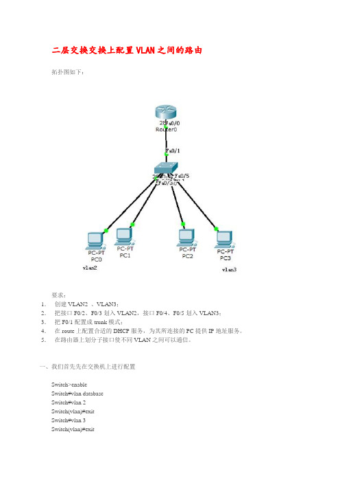
二层交换交换上配置VLAN之间的路由拓扑图如下:要求:1.创建VLAN2 、VLAN3;2.把接口F0/2、F0/3划入VLAN2,接口F0/4、F0/5划入VLAN3;3.把F0/1配置成trunk模式;4.在route上配置合适的DHCP服务,为其所连接的PC提供IP地址服务。
5.在路由器上划分子接口使不同VLAN之间可以通信。
一、我们首先先在交换机上进行配置Switch>enableSwitch#vlan databaseSwitch#vlan 2Switch(vlan)#exitSwitch#vlan 3Switch(vlan)#exitSwitch#conf tEnter configuration commands,one per line. End with CNTL/zSwitch(config)#hostname S1S1(config)#int range f0/2-3S1(config-if-range)#switchport mode accessS1(config-if-range)#switchport access vlan 2S1(config-if-fange)#exitS1(config)#int range f0/4-5S1(config-if-range)#switchport mode accessS1(config-if-range)#switchport access vlan 3S1(config-if-range)#exitS1(config)#interface f0/1S1(config-if)#switchport mode trunkS1(config-if)#exitS1(config)#end二、在路由器上进行配置Router>enRouter#configure terminalEnter configuration commands, one per line. End with CNTL/Z.Router(config)#int f0/0Router(config-if)#no shutdownRouter(config-if)#no ip addressRouter(config-if)#int f0/0.1Router(config-subif)#encapsulation dot1Q 2Router(config-subif)#ip address 192.168.10.1 255.255.255.0Router(config-subif)#no shRouter(config-subif)#exitRouter(config)#int f0/0.2Router(config-subif)#encapsulation dot1Q 3Router(config-subif)#ip add 192.168.20.1 255.255.255.0Router(config-subif)#no shutdownRouter(config-subif)#exitRouter(config)#ip dhcp pRouter(config)#ip dhcp pool vlan2Router(dhcp-config)#network 192.168.10.0 255.255.255.0Router(dhcp-config)#default-router 192.168.10.1Router(dhcp-config)#exitRouter(config)#ip dhcp pool vlan3Router(dhcp-config)#network 192.168.20.1 255.255.255.0Router(dhcp-config)#default-router 192.168.20.1Router(dhcp-config)#exitRouter(config)#ip dhcp excluded-address 192.168.10.1Router(config)#ip dhcp excluded-address 192.168.20.1Router(config)#end三、在主机上修改IP Configuration 选择DHCP选项,自动获取IP地址。

实验二跨交换机实现VLAN利用三层交换机实现VLAN间路由VLANs(虚拟局域网)是一种在物理网络上划分逻辑网络的技术,能够将一个大型的局域网划分为多个较小的逻辑网络。
在本实验中,我们将探讨如何利用三层交换机实现VLAN之间的路由。
第一步:配置实验环境首先,我们需要搭建一个包含两个交换机的实验环境。
使用两台交换机,分别为交换机A和交换机B。
将两台交换机连接起来,可以使用一根网线连接两台交换机的一个端口。
第二步:创建VLAN在交换机A上创建两个VLAN,分别为VLAN10和VLAN20。
在交换机B上同样创建两个VLAN,也为VLAN10和VLAN20。
在每个交换机上配置VLAN的名称和VLAN号码。
第三步:配置端口和VLAN间的关联在交换机 A 上,将连接交换机 B 的端口设置为 trunk 端口。
然后,在交换机 A 上将 VLAN 10 和 VLAN 20 都关联到 trunk 端口。
同样,在交换机 B 上将 VLAN 10 和 VLAN 20 都关联到 trunk 端口。
第四步:配置三层交换机在交换机A上,将其中一个接口设置为三层交换机的端口,并将此端口分配给VLAN10。
同样,在交换机B上也将一个接口设置为三层交换机的端口,并将此端口分配给VLAN20。
第五步:配置路由在交换机A上,配置路由,将VLAN10和VLAN20进行路由。
在交换机B上也需要进行同样的配置。
第六步:测试现在可以测试VLAN之间的路由是否成功。
连接两台主机至交换机A 的接口和交换机B的接口,确保每台主机都在不同的VLAN中。
在主机A上,配置IP地址为VLAN10子网的IP地址,如192.168.10.2、在主机B上,配置IP地址为VLAN20子网的IP地址,如192.168.20.2然后尝试从主机 A ping 主机 B,如果能够成功得到回应,则表示VLAN 之间的路由成功实现。
总结:在本实验中,我们使用两个交换机和一个三层交换机搭建了一个VLAN间路由的环境。

科技资讯2017 NO.21SCIENCE & TECHNOLOGY INFORMATION信 息 技 术13科技资讯 SCIENCE & TECHNOLOGY INFORMATION 随着整个信息行业的蓬勃发展,以及整体硬件价格的持续下降,原本处于高端的三层交换机整被越来越多的应用到了局域网中。
该文利用三层交换机实现了VLAN间的路由。
1 eNSP 华为仿真模拟器eNSP(Enterprise Network Simulation Platform)是一款由华为提供的免费的、可扩展的、图形化操作的网络仿真工具平台,主要对企业网络路由器、交换机进行软件仿真,完美呈现真实设备实景,支持大型网络模拟,让广大用户有机会在没有真实设备的情况下能够模拟演练,学习网络技术。
2 三层交换机实现VLAN 间路由配置实验2.1 实验目标通过三层交换机上的接口配置VLAN网关IP,二层交换机配置中继,PC连接在二层交换机上,将PC的网关设置为三层交换机上的VLAN网关IP,便可实现VLAN间路由。
2.2 网络拓扑图网络拓补图如见图1所示。
2.3 具体实验配置(1)三层交换机上的具体配置。
vlan 10 //配置vlan 10vlan 20 //配置vlan 20vlan 30 //配置vlan 30vlan 40 //配置vlan 40interface Vlanif10 //配置vlan10 IP地址:192.168.10.1ip address 192.168.10.1 255.255.255.0interface Vlanif20 //配置vlan20 IP地址:192.168.20.1ip address 192.168.20.1 255.255.255.0interface Vlanif30 //配置vlan30 IP地址:192.168.30.1ip address 192.168.30.1 255.255.255.0interface Vlanif40 //配置vlan40 IP地址:192.168.40.1ip address 192.168.40.1 255.255.255.0interface GigabitEthernet0/0/1//配置接口模式为中继允DOI:10.16661/ki.1672-3791.2017.21.013三层交换机实现VLAN 间路由徐忠飞(江苏省盐城市大丰区人力资源和社会保障局信息中心 江苏盐城 224100)摘 要:目前局域网规模急剧增加,三层交换机的性能和价格的提升,促使其在网络应用中越来越普遍,因此在一个局域网内可以用三层交换机代替路由器实现VLAN间路由,该文利用华为模拟器给出了具体实例。

三层交换机怎么实现VLAN间路由要想三层交换机实现VLAN间路由有两种实现方式,三层交换启用路由功能或直接使用路由器。
小编这里主要说明如何使用三层交换机实现vlan间的路由。
一、几个在学习过程中比较困惑的概念:1、本地vlan和普通vlan:本地vlan也称管理vlan每台交换机都有一个默认的vlan1,也就是交换机的本地vlan,交换机默认所有的端口都划分在vlan1内。
普通vlan是自己创建的vlan。
普通vlan下转发的帧在通过trunk口之前会被打一个标记(tag:如dot1q),然后在vlan间传输信息;本地vlan下的帧在进入trunk前是不打tag的在进入trunk口时会被打一个nativevlan的tag(即nvtag),在出trunk时会去掉该tag。
我们可以用命令改变交换机的管理vlan。
2、交换机的虚拟接口SVI:我们可以为交换机的vlan创建一个虚拟接口,命令:#interfancevlanvlan-id。
我们可以为这个虚拟接口配置IP。
管理vlan的ip我们可以在远程登录交换机时使用。
对于二层交换机我们仅给交换机的管理vlan配置其SVI的IP地址,如果给普通vlan配置其IP地址没具体作用。
对于三层交换机我们给管理vlan配置其IP地址,用于远程登录使用;给普通vlan配置其SVI的IP地址作为不同vlan下主机的网关。
3、三层交换机的路由功能:想要使用三层交换机的路由功能,首先要启用三层交换机的路由功能,命令:#iprouting。
三层交换机的路由选择可以利用SVI让交换机选择路由;可以启用三层交换机物理接口的三层功能,然后为物理接口配置IP地址。
三层交换机的路由选择功能可以使用静态路由,也可以启动动态路由协议。
二、接下来我做一个具体的例子,网络拓扑如下:拓扑中有两个普通的VLAN,VLAN10和VLAN20,PC7和PC8属于VLAN10,PC5和PC6属于VLAN20。


实训名称:基于三层交换机的vlan之间路由一、实训原理三层交换机有交换机的功能,同时又有路由器的的功能二、实训目的Vlan之间的通信三、实训步骤:拓扑图第一步:配左边的交换机第二步:配右边的交换机第三步:配核心交换机第四步:给PC机配置IP地址具体步骤:第一步:配左边的交换机EnConfVlan 2ExitInt f0/2switchport mode access switchport access vlan 2 int f0/3switchport mode access switchport access vlan 3 int f0/1switchport mode trunk 第二步:配右边的交换机EnConfVlan 4Vlan 5ExitInt f0/2switchport mode access switchport access vlan 4 int f0/3switchport mode access switchport access vlan 5 int f0/1switchport mode trunk 第三步:配核心交换机EnConfVlan 2Vlan 3Vlan 5ExitInt vlan 2Ip add 192.168.2.254 255.255.255.0Int vlan 3Ip add 192.168.3.254 255.255.255.0Int vlan 4Ip add 192.168.4.254 255.255.255.0Int vlan 5Ip add 192.168.5.254 255.255.255.0Exitint range f0/1-2switchport trunk encapsulation dot1q switchport mode trunkexitip routing第四步:给PC机配置IP地址四、实训结果从PC0 ping PC1。

今天我们来演示VLAN间路由的实验,配置方法有多种,我们首先来演示利用三层交换机实现V LAN间路由。
其实该实验还有另外一种实现方法:直接在交换机的物理接口配置IP而不用划分VLAN ,下面演示的是在交换机上划分VLAN的实现方法。
实验拓扑图:实验环境说明:1.分别启用路由器R1 、R2和交换机SW1;2.将路由器R1的Fa0/0端口的ip设为:192.168.1.2/24,关闭路由功能,用来模拟PC1,同时将默认网关设为:192.168.1.1;3.将路由器R2的Fa0/0端口的ip设为:192.168.0.2/24,关闭路由功能,用来模拟PC2,同时将默认网关设为:192.168.0.1;4.在交换机SW1上分别划分VLAN14、VLAN15两个VLAN,启用路由功能,用来充当三层交换机;5.将交换机SW1的Fa1/14端口的ip设为:192.168.0.1/24,并将该端口加入到VLAN14中;6.将交换机SW1的Fa1/15端口的ip设为:192.168.1.1/24,并将该端口加入到VLAN15中;实验结果要求:要求两台路由器可以相互ping通对方。
配置过程详解:交换机SW1的配置清单:1.开启交换机的路由功能,充当三层交换机使用SW1(config)#ip routingSW1(config)#exit2.在交换机SW1上划分VLAN:SW1#vlan dataSW1(vlan)#vlan 14SW1(vlan)#vlan 15SW1(vlan)#exit3.将交换机SW1的两个端口分别划入相应的VLAN:SW1(config)#int fa1/14SW1(config-if)#speed 100SW1(config-if)#duplex fullSW1(config-if)#switchport mod accSW1(config-if)#switchport acc vlan 14SW1(config-if)#exitSW1(config)#int fa1/15SW1(config-if)#speed 100SW1(config-if)#duplex fullSW1(config-if)#switchport mod accSW1(config-if)#switchport acc vlan 15SW1(config-if)#exit4.分别为每个VLAN设置ip:SW1(config)#int vlan 14SW1(config-if)#ip add 192.168.0.1 255.255.255.0SW1(config-if)#no shutSW1(config-if)#exitSW1(config)#int vlan 15SW1(config-if)#ip add 192.168.1.1 255.255.255.0SW1(config-if)#no shutSW1(config-if)#exit路由器R1的配置清单:R1(config)#no ip routing //关闭路由功能R1(config)#ip default-gateway 192.168.1.1 //配置默认网关R1(config)#int fa0/0 //进入端口模式R1(config-if)#speed 100 //设置速率R1(config-if)#duplex full //设为全双工模式R1(config-if)#ip add 192.168.1.2 255.255.255.0 //配置ip地址和子网掩码R1(config-if)#no shut //启动端口R1(config-if)#exit路由器R2 的配置清单:R2(config)#no ip routingR2(config)#ip default-gateway 192.168.0.1R2(config)#int fa0/0R2(config-if)#speed 100R2(config-if)#duplex fullR2(config-if)#ip add 192.168.0.2 255.255.255.0R2(config-if)#no shutR2(config-if)#exit验证实验结果:R1pingR2:R1r#ping 192.168.0.2Type escape sequence to abort.Sending 5, 100-byte ICMP Echos to 192.168.0.2, timeout is 2 seconds:!!!!!Success rate is 100 percent (5/5), round-trip min/avg/max = 120/162/216 ms R2pingR1:R2#ping 192.168.1.2Type escape sequence to abort.Sending 5, 100-byte ICMP Echos to 192.168.1.2, timeout is 2 seconds:!!!!!Success rate is 100 percent (5/5), round-trip min/avg/max = 120/137/188 ms OK ,到此VLAN间路由实验(三层交换机实现法)就圆满完成了。

通过三层交换机实现VLAN 间路由【实验名称】通过三层交换机实现VLAN 间路由【实验目的】掌握如何通过三层交换机实现VLAN 间路由。
【背景描述】假设某企业有2个主要部门:销售部和技术部,其中销售部门的个人计算机系统分散连接在2台交换机上,他们之间需要相互进行通信,销售部和技术部也需要进行相互通讯,现要在交换机上做适当配置来实现这一目标。
【实现功能】使在同一VLAN 里的计算机系统能跨交换机进行相互通信,而在不同VLAN 里的计算机系统也能进行相互通信。
【实验拓扑】【实验设备】S2126G (1台)、S3550-24(1台)【实验步骤】第一步:在交换机SwitchA 上创建Vlan 10,并将0/5端口划分到Vlan 10中。
SwitchA # configure terminal !进入全局配置模式。
SwitchA(config)# vlan 10 !创建Vlan 10。
SwitchA(config-vlan)# name sales !将Vlan 10命名为sales 。
SwitchA(config-vlan)#exitSwitchA(config)#interface fastethernet 0/5 !进入接口配置模式。
SwitchA(config-if)#switchport access vlan 10 !将0/5端口划分到Vlan 10。
验证测试:验证已创建了Vlan 10,并将0/5端口已划分到Vlan 10中。
SwitchA#show vlan id 10VLAN Name Status Ports---- -------------------------------- --------- -------------------------------10 sales active Fa0/5第二步:在交换机SwitchA 上创建Vlan 20,并将0/15端口划分到Vlan 20中。

华为三层交换机VLAN间路由配置详解实验拓扑实验需求1、C1与C3属于VLAN10,C2与C4属于VLAN20,在SW1上创建VLAN100做上行VLAN2、在SW1上终结所有VLAN3、在所有VLAN成员使用DHCP获取IP4、全网互通IP规划VLAN10 :192.168.10.0/24VLAN20 :192.168.20.0/24VLAN100:192.168.100.10/24R1 G0/0/0:192.168.100.1/24SW1配置:<SW1>system-view //进入系统视图[SW1]vlan batch 10 20 100 //创建VLAN[SW1]dhcp enable //开启DHCP服务[SW1]inter g0/0/1[SW1-GigabitEthernet0/0/1]port hybrid pvid vlan 10[SW1-GigabitEthernet0/0/1]port hybrid untagged vlan 10 //将接口以untagged方式加入vlan[SW1-GigabitEthernet0/0/1]int g0/0/2[SW1-GigabitEthernet0/0/2]port hybrid pvid vlan 20[SW1-GigabitEthernet0/0/2]port hybrid untagged vlan 20[SW1-GigabitEthernet0/0/2]int g0/0/10[SW1-GigabitEthernet0/0/10]port hybrid pvid vlan 100[SW1-GigabitEthernet0/0/10]port hybrid untagged vlan 100 [SW1-GigabitEthernet0/0/10]int g0/0/24[SW1-GigabitEthernet0/0/24]port hybrid tagged vlan 10 20 //将接口以tagged方式加入vlan[SW1-GigabitEthernet0/0/24]quit[SW1]inter vlan 10 //进入vlan10[SW1-Vlanif10]ip address 192.168.10.1 24 //配置vlan10成员的网关[SW1-Vlanif10]dhcp select interface //将dhcp应用在接口[SW1-Vlanif10]int vlan 20[SW1-Vlanif20]ip address 192.168.20.1 24[SW1-Vlanif20]dhcp select interface[SW1-Vlanif20]int vlan 100[SW1-Vlanif100]ip address 192.168.100.10 24SW2配置:<SW2>system-view[SW2]vlan batch 10 20[SW2]inter g0/0/1[SW2-GigabitEthernet0/0/1]port hybrid pvid vlan 10[SW2-GigabitEthernet0/0/1]port hybrid untagged vlan 10[SW2-GigabitEthernet0/0/1]int g0/0/2[SW2-GigabitEthernet0/0/2]port hybrid pvid vlan 20[SW2-GigabitEthernet0/0/2]port hybrid untagged vlan 20[SW2-GigabitEthernet0/0/2]int g0/0/24[SW2-GigabitEthernet0/0/24]port hybrid tagged vlan 10 20 R1配置:<R1>system-view[R1]ip route-static 0.0.0.0 0.0.0.0 192.168.100.10[R1]inter G0/0/0[R1-GigabitEthernet0/0/0]ip address 192.168.100.1 24测试:。

三层交换机路由配置一、三层交换机VLAN间路由建立某公司有两个主要部门:技术部和销售部,分处于不同的办公室,为了安全和便于管理对两个部门的主机进行了VLAN划分,技术部和销售部分处于不同VLAN。
现由于业务需要销售部和技术部的主机能够相互访问,获得相应资源,两个部门的交换机通过一台三层交换机进行连接。
在交换机上建立2个Vlan:Vlan10分配给技术部及Vlan20分配给销售部。
为了实现两部门的主机能够相互访问,在三层交换机上开启路由功能,并在Vlan10中设置IP地址为192.168.10.1;在Vlan20中设置IP地址为192.168.20.1,查看三层交换机路由表,会发现在三层交换机路由表内有2条直连路由信息,实现在不同网络之间路由数据包,从而达到2个部门的主机可以相互访问,拓朴图如图所示。
第1步:开启三层交换机路由功能Switch#configure terminalSwitch(config)#hostname s3550S3550(conifg)#ip routing第2步:建立Vlan,并分配端口S3550(conifg)#vlan 10S3550(config-vlan)#name salesS3550(config-vlan)#exitS3550(conifg)#vlan 20S3550(config-vlan)#name technicalS3550(config-vlan)#exitS3550(conifg)#S3550(conifg)#interface fastethernet 0/10S3550(conifg-if)#switchport mode accessS3550(conifg-if)#switchport access vlan 10S3550(conifg-if)#exitS3550(conifg)# interface fastethernet 0/20S3550(conifg-if)#switchport mode accessS3550(conifg-if)#switchport access vlan 20S3550(config-vlan)#exitS3550(config)#第3步:配置三层交换机端口的路由功能S3550(config)#interface vlan 10S3550(conifg-if)#ip address 192.168.10.1 255.255.255.0 S3550(conifg-if)#no shutdownS3550(conifg-if)#exitS3550(config)#interface vlan 20S3550(conifg-if)#ip address 192.168.20.1 255.255.255.0S3550(conifg-if)#no shutdownS3550(conifg-if)#endS3550#第4步:查看路由表S3550#show ip route第5步:测试三层交换机Vlan间路由功能二、三层交换机与路由器间静态路由的建立某校园局域网由若干台交换机构成,现学校需要将校园网接入互联网,学校在出口使用一台路由器连接互联网。
Cisco − How To Configure InterVLAN Routing on Layer 3 SwitcCisco − How To Configure InterVLAN Routing on Layer 3 SwitchesTable of ContentsHow To Configure InterVLAN Routing on Layer 3 Switches (1)Introduction (1)Before You Begin (1)Conventions (1)Prerequisites (1)Components Used (2)Configuring InterVLAN Routing (2)Task (2)Step−by−Step Instructions (3)Verify (5)Troubleshoot (5)Troubleshooting Procedure (5)Related Information (6)How To Configure InterVLAN Routing on Layer 3 SwitchesIntroductionBefore You BeginConventionsPrerequisitesComponents UsedConfiguring InterVLAN RoutingTaskStep−by−Step InstructionsVerifyTroubleshootTroubleshooting ProcedureRelated InformationIntroductionLayer 3 Catalyst switches incorporate routing functionality which allows the switch to perform interVLAN routing. This document provides the configuration and troubleshooting steps applicable to this capability.Note: This document uses a Catalyst 3550 as an example, however, the concepts can also be applied to other Layer 3 switches running Cisco IOS® (for example, Catalyst 4000 Series with Sup II+ or higher, or Catalyst 6000 Series running Cisco IOS on the Supervisor and MSFC).Before You BeginConventionsFor more information on document conventions, see the Cisco Technical Tips Conventions.PrerequisitesBefore attempting this configuration, please ensure that you meet the following prerequisites:InterVLAN routing on the Catalyst 3550 has certain software requirements to support interVLAN •routing on the switch. Please refer to the table below to determine whether your switch can support interVLAN routingImage Type and Version InterVLAN RoutingCapabilityEnhanced Multilayer Image (EMI) −All VersionsYesStandard Multilayer Image (SMI) −prior to 12.1(11)EA1NoStandard Multilayer Image (SMI) −12.1(11)EA1 and laterYesFor more information on the differences between SMI and EMI, refer to the document UpgradingSoftware Images on Catalyst 3550 Series Switches Using the Command Line Interface. The document also provides the procedure to upgrade the IOS code to a version that supports interVLAN routing.This document assumes that layer 2 has been configured and that the devices within the same VLAN •connected to the 3550 can communicate with one another. If you need information on configuringVLANs, access ports and trunking on the 3550, please refer to Creating Ethernet VLANs on Catalyst Switches or the Catalyst 3550 Software Configuration Guide for the specific IOS version you arerunning on the switch.Components UsedThe information in this document is based on the software and hardware versions below.•Catalyst 3550−48 running 12.1(12c)EA1 EMI Software releaseThe information presented in this document was created from devices in a specific lab environment. All of the devices used in this document started with a cleared (default) configuration. If you are working in a live network, ensure that you understand the potential impact of any command before using it.Configuring InterVLAN RoutingTaskIn this section, you are presented with the information to configure the features described in this document.The following logical diagram explains a simple interVLAN routing scenario. The scenario can be expanded to include a multi−switch environment by first configuring and testing inter−switch connectivity across the network before configuring the routing capability. For such a scenario using a Catalyst 3550, please refer to the document Configuring InterVLAN Routing with Catalyst 3550 Series Switches.Step−by−Step InstructionsDo the following to configure a switch to perform interVLAN routing.Enable routing on the switch using the ip routing command. Even if IP routing was previously1.enabled, this step ensures that it is indeed activated.Switch(config)#ip routingNote: If the switch does not accept the ip routing command, you will need to upgrade to either SMI image 12.1(11)EA1 or later, or an EMI image, and repeat this step. Refer to the Prerequisites section for more information.Tip: Check the show running−configuration and verify whether ip routing is enabled. Thecommand, if enabled, will appear towards the top of the output.hostname Switch!!ip subnet−zeroip routing!vtp domain Ciscovtp mode transparent2.Make note of the VLANs that you want to route between. In our example, we want to route traffic between VLANs 2, 3 and 10.3.Use the show vlan command to verify that the VLANs exist in the VLAN database. If they do not exist, you must add them on the switch.Switch#vlan databaseSwitch(vlan)#vlan 2VLAN 2 added:Name: VLAN0002Switch(vlan)#vlan 3VLAN 3 added:Name: VLAN0003Switch(vlan)#vlan 10VLAN 10 added:Name: VLAN0010Switch(vlan)#exitAPPLY completed.Exiting....Tip: You can use VTP to propagate these VLANs to other switches. Refer to the document Understanding and Configuring VLAN Trunk Protocol (VTP).4.Determine the IP addresses you want to assign to the VLAN interface on the switch. For the switch to be able to route between the VLANs, the VLAN interfaces must be configured with an IP address. When the switch receives a packet destined for another subnet/VLAN, the switch looks at the routing table to determine where to forward the packet. The packet is then passed to the VLAN interface of the destination and in turn it is sent to the port where the end device is attached.5.Configure the VLAN interfaces with the IP address identified in Step 4.Switch#conf tEnter configuration commands, one per line. End with CNTL/Z.Switch(config)#interface Vlan2Switch(config−if)#ip address 10.1.2.1 255.255.255.0Switch(config−if)#no shutdownRepeat this process for all VLANs identified in Step 1.Configure the interface to the default router. In this scenario we have a Layer 3 FastEthernet port.6.Switch(config)#interface FastEthernet 0/1Switch(config−if)#no switchportSwitch(config−if)#ip address 200.1.1.1 255.255.255.0Switch(config−if)#no shutdownThe no switchport command makes the interface Layer 3 capable. Also notice that the IP address is in the same subnet as the default router.Note: This step can be omitted if the switch can reach the default router through a VLAN. In its place, configure an IP address for that VLAN interface.Configure the default route for the switch7.Switch(config)#ip route 0.0.0.0 0.0.0.0 200.1.1.2From the diagram in the Task section, note that the IP address of the default router is 200.1.1.2. If the switch receives a packet for a network not in the routing table, it forwards it to the default gateway for further processing From the switch verify that you can ping the default router.Note: The ip default−gateway command is used to specify the default gateway when routing is not enabled. However, in this case, routing is enabled (from Step 1) hence the ip default−gateway command is unnecessary.Configure your end devices to use the respective Catalyst 3550 VLAN interface as their default gateway For example, devices in VLAN 2 should use the interface VLAN 2 IP address as its default gateway. Refer to the appropriate client configuration guide for more information on designating the default gateway.8. VerifyThis section provides information you can use to confirm your configuration is working properly.Certain show commands are supported by the Output Interpreter Tool ( registered customers only ) , which allows you to view an analysis of show command output.show ip route − Provides a snapshot of the routing table entries.Cat3550#show ip routeCodes: C − connected, S − static, I − IGRP, R − RIP, M − mobile, B − BGPD − EIGRP, EX − EIGRP external, O − OSPF, IA − OSPF inter areaN1 − OSPF NSSA external type 1, N2 − OSPF NSSA external type 2E1 − OSPF external type 1, E2 − OSPF external type 2, E − EGPi − IS−IS, L1 − IS−IS level−1, L2 − IS−IS level−2, ia − IS−IS inter area * − candidate default, U − per−user static route, o − ODRP − periodic downloaded static routeGateway of last resort is 200.1.1.2 to network 0.0.0.0200.1.1.0/30 is subnetted, 1 subnetsC 200.1.1.0 is directly connected, FastEthernet0/4810.0.0.0/24 is subnetted, 3 subnetsC 10.1.10.0 is directly connected, Vlan10C 10.1.3.0 is directly connected, Vlan3C 10.1.2.0 is directly connected, Vlan2S* 0.0.0.0/0 [1/0] via 200.1.1.2Note that the routing table has an entry for each VLAN interface subnet. Hence, devices in VLAN 3can communicate with devices in VLAN 10, VLAN 2 and vice versa. Also, the default route with the next hop 200.1.1.2 allows the switch to forward traffic to the gateway of last resort (for traffic the switch cannot route).• show ip interface brief − Lists a brief summary of an interface's IP information and status. This command can be used to verify that the VLAN interfaces and ports on the switch are up/up.• TroubleshootThis section provides information you can use to troubleshoot your configuration.Troubleshooting ProcedureBelow is troubleshooting information relevant to this configuration. Follow the instructions to troubleshoot your configuration.Verify you have Layer 2 connectivity by issuing ICMP pings.If you are not able to ping between two devices on the same VLAN on the same switch,verify that your source and destination ports have devices connected to them and are assignedto the same VLAN. For more information, refer to the document Creating Ethernet VLANs♦ 1.on Catalyst Switches.If you are not able to ping between two devices on the same VLAN but not on the sameswitch, verify that trunking is configured properly and that the native VLAN matches on both sides of the trunk.♦ Initiate a ICMP ping from an end device connected to the Catalyst 3550 to its corresponding VLAN interface. In this example, you could use a host on VLAN 2 (10.1.2.2) and ping Interface VLAN 2(10.1.2.1). If you are not able to ping the interface, verify that the host's default gateway points to the corresponding VLAN interface IP address and that the subnet masks match. For example, the default gateway of the device on VLAN 2 should point to Interface VLAN 2 (10.1.2.1).Also verify the interface VLAN status by issuing the show ip interface brief command.If the interface status is administratively down, issue the no shutdown command in theVLAN interface configuration mode.♦ If the interface status is down/down, verify the VTP configuration and that the VLANs have been added to the VLAN database. You should also check to see if a port is assigned to theVLAN and whether it is in the Spanning Tree forwarding state.♦ 2. Initiate a ping from an end device in one VLAN to the interface VLAN on another VLAN to verify that the switch can route between VLANs. In this example we would ping from VLAN 2 (10.1.2.1) to Interface VLAN 3 (10.1.3.1) or Interface VLAN 10 (10.1.10.1). If the ping fails, verify that IP routing is enabled and that the VLAN interfaces status is up by issuing the show ip interface brief command.3. Initiate a ping from the end device in one VLAN to the end device in another VLAN. For example, a device on VLAN 2 should be able to ping a device on VLAN 3. If the ping test was successful in step 3, but fails to reach the end device on other VLAN, verify that the default gateway on the connected device is configured correctly.4. If you are not able to reach the Internet or corporate network, verify that the default route on the 3550is pointing to the correct IP address on the default router. Also verify that the IP address and subnet mask on the switch are configured correctly.5. Related InformationConfiguring InterVLAN Routing with Catalyst 3550 Series Switches• Configuring Layer 3 Interfaces for the Catalyst 4000• Technical Support − Cisco Systems• All contents are Copyright © 1992−2003 Cisco Systems, Inc. All rights reserved. Important Notices and Privacy Statement.。