PDV-P8001;中文规格书,Datasheet资料
- 格式:pdf
- 大小:111.61 KB
- 文档页数:2
半导体激光打标机使用说明书深圳市华天世纪激光科技有限公司前言欢迎您选用我公司生产的HT-DP50系列激光打标机,如果您是首次使用此款型号的激光打标机,在通电前请务必仔细阅读本使用手册。
DP50系列激光设备已采用了尽可能全面的安全防范措施,以确保拥护人身安全及设备的自身安全,虽然如此,对本机的不正确使用、维护、改制等仍可能对操作者或机器造成各种损害。
防止激光辐射的泄漏:DP50系列激光设备采用封闭的激光光路设计,可以有效地防止激光辐射的泄漏。
对本机电器设备进行的维护、调整必须由经过培训的对本机各部分均较为熟悉的专业技术人员进行,且需特别注意以下几点:1、若某部件在维护调整时不需要运行,请勿接通该部分的电源。
2、在更换激光器模块时,切勿接通设备电源。
3、机器应有良好的接地,并应对此作定期检查。
4、尽可能只用一只手操作电气设备,以防止在人体上构成回路。
5、在高压电路上操作时,应使用合格的,绝缘良好的工具。
设备的测试,有些需采用一些特殊的测量技术或设备。
测试参数的选择应由熟悉本机操作和相关设备使用的技术人员决定。
敬告用户:1、除本手册所规定的操作外,对机器的任何其他操作,都可能使操作者遭受危险的激光辐射!2、若激光束照射到易燃材料上时,将会引起火灾甚至爆炸,应注意不得把该类材料放置到光路上或激光束有可能照到的地方!3、激光器正常工作期间,设备内部不得增设任何零件及物品。
除非经过特别授权,否则不得在密封罩打开的状态下使用本机。
欢迎用户提出建议,请与下列地址联系:中华人民共和国深圳市华天世纪激光科技有限公司邮政编码:518001电话:国内业务部:0国际业务部:+86-售后服务部:0传真:(FAX):1主页:H地址:深圳市罗湖区人民北路物资大院综合楼1-2层需要采购或技术支持时,请与就近的销售服务商联系目录第一部分半导体激光打标机各部件原理与使用说明............................................................................. - 1 -1.激光原理....................................................................................................................................... - 1 -2.光学系统....................................................................................................................................... - 1 -3.各主要部件原理与技术说明....................................................................................................... - 2 -扩束镜........................................................................................................................................... - 4 -激光电源....................................................................................................................................... - 4 -声光Q开关.................................................................................................................................. - 8 -声光Q开光驱动电源.................................................................................................................. - 8 -1.电气安装连线....................................................................................................... - 8 -1、数码窗................................................................................................................. - 10 -2、RUN/STOP(运行)指示灯................................................................................. - 10 -3、ALARM(报警)指示灯....................................................................................... - 10 -4、TEST(测试)指示灯......................................................................................... - 10 -5、M1、M2、M3指示灯............................................................................................ - 10 -6、按键说明............................................................................................................. - 10 -7、电源开关............................................................................................................. - 11 -“F-θ”镜组 ............................................................................................................................. - 11 -光学扫描振镜............................................................................................................................. - 11 -冷水机使用说明......................................................................................................................... - 12 -第二部分打标控制软件使用说明....................................................................................................... - 18 -第一章概述............................................................................................................................................... - 18 -EzCad2软件简介....................................................................................................................................... - 18 -1.1.1 软件安装........................................................................................................................... - 18 -1.1.2 软件功能........................................................................................................................... - 18 -1.1.3 界面说明........................................................................................................................... - 18 -第二章文件菜单....................................................................................................................................... - 20 -新建(N) ............................................................................................................................................... - 20 -打开(O) ............................................................................................................................................... - 20 -保存(S),另存为(A) .......................................................................................................................... - 21 -打印..................................................................................................................................................... - 22 -获取扫描图像(m) ............................................................................................................................... - 22 -系统参数(P) ........................................................................................................................................ - 23 -2.6.1 常规................................................................................................................................... - 23 -2.6.2 颜色................................................................................................................................... - 24 -2.6.3 工作空间........................................................................................................................... - 24 -2.6.4 自动备份........................................................................................................................... - 24 -2.6.5 移动旋转........................................................................................................................... - 25 -2.6.6 插件管理器....................................................................................................................... - 25 -2.6.7 语言/Language .................................................................................................................. - 25 -最近文件............................................................................................................................................. - 26 -退出(X) ............................................................................................................................................... - 26 -对象列表............................................................................................................................................. - 26 -对象属性栏......................................................................................................................................... - 26 -第三章编辑............................................................................................................................................... - 28 -撤消(U)/恢复(R) ................................................................................................................................. - 28 -剪切(T)/复制(C)/粘贴(P) ................................................................................................................... - 28 -组合/分离组合.................................................................................................................................... - 28 -群组/分离群组.................................................................................................................................... - 29 -填充..................................................................................................................................................... - 29 -第四章绘制菜单....................................................................................................................................... - 33 -点(D) ................................................................................................................................................... - 33 -曲线..................................................................................................................................................... - 34 -矩形..................................................................................................................................................... - 34 -圆- 35 -椭圆..................................................................................................................................................... - 35 -多边形................................................................................................................................................. - 36 -文字..................................................................................................................................................... - 36 -4.7.1文字字体参数.................................................................................................................... - 36 -4.7.2曲线排文本参数................................................................................................................ - 38 -4.7.3条形码字体参数................................................................................................................ - 40 -一维条形码......................................................................................................................... - 42 -二维条形码......................................................................................................................... - 43 -1.PDF417条码......................................................................................................... - 43 -2.DataMatrix条码 ................................................................................................... - 43 -4.7.4变量文本............................................................................................................................ - 44 -键盘............................................................................................................................. - 44 -日期............................................................................................................................. - 45 -显示为:序列号......................................................................................................... - 47 -列表文件..................................................................................................................... - 50 -动态文件..................................................................................................................... - 51 -位图..................................................................................................................................................... - 52 -矢量文件............................................................................................................................................. - 56 -延时器................................................................................................................................................. - 57 -输入口................................................................................................................................................. - 57 -输出口................................................................................................................................................. - 57 -直线..................................................................................................................................................... - 58 -图形选取............................................................................................................................................. - 58 -节点编辑............................................................................................................................................. - 59 -第五章修改菜单....................................................................................................................................... - 62 -变换..................................................................................................................................................... - 62 -5.1.1移动.................................................................................................................................... - 62 -5.1.2 旋转................................................................................................................................... - 63 -5.1.3镜像.................................................................................................................................... - 63 -5.1.4缩放.................................................................................................................................... - 64 -5.1.5倾斜.................................................................................................................................... - 64 -造形..................................................................................................................................................... - 65 -曲线编辑............................................................................................................................................. - 66 -对齐..................................................................................................................................................... - 66 -jsf字体................................................................................................................................................ - 67 -第六章查看菜单....................................................................................................................................... - 69 -观察..................................................................................................................................................... - 69 -标尺,网格点,辅助线..................................................................................................................... - 70 -捕捉网格............................................................................................................................................. - 70 -捕捉辅助线......................................................................................................................................... - 70 -捕捉对象............................................................................................................................................. - 70 -系统工具栏、视图工具栏、绘制工具栏、状态栏、对象列表栏、对象属性栏 ......................... - 70 -第七章帮助............................................................................................................................................... - 71 -关于EzCad(A) ................................................................................................................................... - 71 -第八章加工............................................................................................................................................... - 72 -笔列表................................................................................................................................................. - 72 -加工参数库......................................................................................................................................... - 73 -软件参数设置..................................................................................................................................... - 79 -8.4.1配置参数设置.................................................................................................................... - 79 -8.4.2区域尺寸参数.................................................................................................................... - 79 -8.4.3激光控制............................................................................................................................ - 80 -.端口参数.................................................................................................................................... - 84 -加工参数设置步骤............................................................................................................................. - 85 -8.5.1 调节开始段延时............................................................................................................... - 85 -8.5.2 调节结束段延时............................................................................................................... - 88 -8.5.3 调节拐角延时................................................................................................................... - 89 -扩展轴分割标刻模块......................................................................................................................... - 91 -8.6.1模块功能说明.................................................................................................................... - 91 -8.6.2 扩展轴参数....................................................................................................................... - 92 -8.6.3单扩展轴功能参数............................................................................................................ - 95 -1)单轴功能的开启设置.............................................................................................................. - 95 -2)各参数的功能定义................................................................................................................. - 96 -3)单扩展轴参数调试说明......................................................................................................... - 99 -8.6.4 双扩展轴功能参数......................................................................................................... - 100 -附件:电流映射参数....................................................................................................................... - 101 -第一部分半导体激光打标机各部件原理与使用说明HT-DP50系列激光打标设备由半导体激光器泵浦模块、Q驱动器、冷水机组、光学聚焦镜头、激光电源、半自动对焦控制器、计算机控制系统(包括计算机和专用接口板)、光学扫描振镜及其驱动器、X-Y工作平台、等部件组成。
查询TCD1200D供应商捷多邦,专业PCB打样工厂,24小时加急出货LSD101-T1200LSD101-T1206LSD101-T1208LSD101-T1251单路模拟输出黑白线扫描CCD驱动板B/W LINESCAN CCD DRIVER用户手册©2007 All Rights Reserved目 录产品功能描述 (1)主要技术指标 (2)驱动板的使用 (3)1.注意事项 (3)2. IO输入输出接口定义 (3)3. 功能设置拨码开关 (4)4. 使用驱动板 (5)信号及时序 (5)1. 输出信号描述 (5)2. 内同步驱动模式 (5)3. 外同步工作模式 (6)积分步长及积分时间设定 (7)CCD模拟输出信号调整 (8)外形及尺寸 (9)修订信息 (10)产品功能描述LSD101-T1200/T1206/T1208/T1251驱动板是我公司专为日本TOSHIBA(东芝)公司生产的TCD1200D/TCD1206SUP/TCD1208AP/TCD1251UD黑白线扫描CCD设计的驱动电路板,驱动板设计上结合了我公司技术人员多年线扫描CCD 驱动的设计应用经验,采用高速同步驱动电路设计技术,产品具有时序一致性好、稳定可靠的优点。
驱动板主要具备以下功能及特点:严格按照芯片手册的定义提供满足驱动要求的驱动信号及时序;采用小型化表面贴装元件设计的小尺寸单板式驱动结构;提供完全内外两种同步驱动模式,内同步驱动上电即可工作;将CCD原始输出的反向偏置输出信号转换为正向零偏置模拟输出信号;积分时间可分16级线性调整;积分时间步长4级可设定;驱动频率2档可设定;提供行有效输出信号及像素采样输出时钟;具备一定的电源过流、过热保护及抗干扰电路措施。
图1 LSD101-T1200/T1206/T1208/T1251实物标注图主要技术指标表1 主要技术指标参数技术指标最小值典型值最大值LSD101-T1200LSD101-T1206 LSD101-T12081MHz 2MHz 2MHz 驱动频率①LSD101-T1251 2MHz 4MHz 4MHz LSD101-T1200LSD101-T1206 —— —— 891(Hz ) LSD101-T1208 —— —— 900(Hz ) 行扫描频率②LSD101-T1251———— 1432(Hz )数字输出信号高电平电压 4.5V 5.0V VCC 数字输出信号低电平电压 0V 0.1V 0.7V EX_INT 输入信号高电平电压 3.0V 4.0V VCC EX_INT 输入信号低电平电压 0V 0.2V 0.5V 模拟输出信号电压 0.1V —— VCC① 驱动频率2档可设定,通过驱动板上拨码开关设定。
DMVCD系列隔离开关使用说明书伊顿电气有限公司Eaton Electrical Ltd.装箱单随机文件和附件产品型号说明书合格证手柄操作轴柜外操作机构标准件限制件DMV63CD/3.41111DMV100CD/3.411111DMV63CD/3.4G 111111DMV100CD/3.4G 1111111DMV160-630CD/3.41111DMV160-630CD/3.4G 11111DMV1000CD/3.41112DMV1000CD/3.4G 111112DMV1250-1600CD/3.41114DMV1250-1600CD/3.4G111114尊敬的用户:欢迎您使用本公司生产的DMVCD系列隔离开关产品!为了您能安全正确地使用本系列产品,敬请您在安装调试和使用前熟读本说明书。
本产品符合GB/T14048.3、IEC60947-3标准,并通过了国家CCC认证。
目录一.用途 (4)二.产品的工作条件 (4)三.结构与特点 (4)四.主要规格及技术参数 (4)五.外型与安装尺寸 (5)六.安装方法 (9)七.使用与维修 (14)八.订货须知 (14)一、用途DMVCD系列隔离开关(以下简称开关)适用于交流50Hz,额定电压415V以下,额定电流为63~1600A。
在配电系统中做不频繁接通与分断电路及隔离电路用。
二、产品的工作条件开关在如下条件下可靠运行:安装地点的海拔高度不超过2000米;周围空气温度不超过+40℃,而且其24h内的平均温度值不超过+35℃;周围空气温度的下限为-5℃;最高温度为+40℃时,空气的相对湿度不超过50%,在较低的温度下可以允许有较高的相对湿度,例如20℃时达90%。
对由于温度变化偶尔产生的凝露应采取特殊的措施;污染等级为3级。
注:若预期使用条件与以上标准不同,应在下单前提出。
三、结构与特点开关由不饱和聚酯玻璃纤维增强模塑料(DMC)制造的外壳;弹簧储能加速机构能快速实现接通与分断;触头结构为并联双断点两个分离触头面,并由片状弹簧保证触头压力;开关能够自动确定通断的极限位置,而且具有明显的通断标记来指示通断位置。
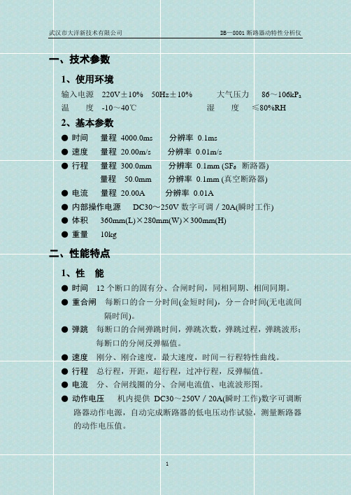
一、技术参数1、使用环境输入电源220V±10% 50Hz±10% 大气压力86~106kP a 温度-10~40℃湿度≤80%RH2、基本参数●时间量程4000.0ms 分辨率0.1ms●速度量程20.00m/s 分辨率0.01m/s●行程量程300.0mm 分辨率0.1mm (SF6 断路器)量程50.0mm 分辨率0.1mm (真空断路器)●电流量程20.00A 分辨率0.01A●内部操作电源DC30~250V数字可调/20A(瞬时工作)●体积360mm(L)×280mm(W)×300mm(H)●重量10kg二、性能特点1、性能●时间12个断口的固有分、合闸时间,同相同期、相间同期。
●重合闸每断口的合-分时间(金短时间),分-合时间(无电流间隔时间)。
●弹跳每断口的合闸弹跳时间,弹跳次数,弹跳过程,弹跳波形;每断口的分闸反弹幅值。
●速度刚分、刚合速度,最大速度,时间-行程特性曲线。
●行程总行程,开距,超行程,过冲行程,反弹幅值。
●电流分、合闸线圈的分、合闸电流值、电流波形图。
●动作电压机内提供DC30~250V/20A(瞬时工作)数字可调断路器动作电源,自动完成断路器的低电压动作试验,测量断路器的动作电压值。
2、特点◆开关动作一次,得到以上所有数据及相应的波形、图谱。
◆万能通用式测速传感器,安装极为方便,简捷。
◆适用于国内外生产的所有型号的SF6开关、GIS组合电器、真空开关、油开关。
◆主机可存储16组现场分、合闸试验结果,机内实时时钟,便于存档保存试验日期、时间。
◆主机大屏幕、宽温带、背景光液晶、全中文显示所有数据及图谱,液晶对比度电子调节、断电记忆。
◆中文菜单操作,使用方便。
◆内置全中文打印机打印所有数据及图谱。
◆刚分、刚合速度相应地编制了分析软件,根据需要,任意分析,适用于国内外任何一家开关厂生产的任一型号开关的测速。
◆仪器配有与PC机联机的RS-232接口及《DB-8001(Ⅱ)断路器远程诊断分析管理系统Windows中文版》分析软件,可与PC机联机操作,试验结果直接存入硬盘,也可输出到各类针式、激光或喷墨打印机打印试验报告,使现场试验计算机化。
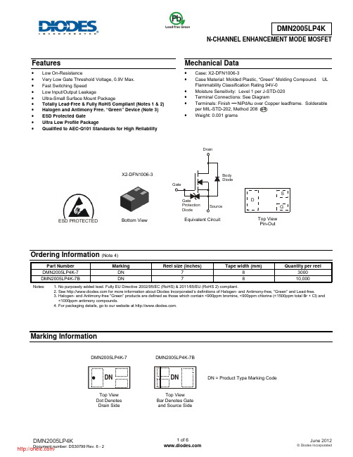
N-CHANNEL ENHANCEMENT MODE MOSFETFeatures• Low On-Resistance • Very Low Gate Threshold Voltage, 0.9V Max. • Fast Switching Speed • Low Input/Output Leakage • Ultra-Small Surface Mount Package • Totally Lead-Free & Fully RoHS Compliant (Notes 1 & 2) • Halogen and Antimony Free. “Green” Device (Note 3) • ESD Protected Gate • Ultra Low Profile Package • Qualified to AEC-Q101 Standards for High ReliabilityMechanical Data• Case: X2-DFN1006-3 • Case Material: Molded Plastic, “Green” Molding Compound. ULFlammability Classification Rating 94V-0 • Moisture Sensitivity: Level 1 per J-STD-020 • Terminal Connections: See Diagram • Terminals: Finish ⎯NiPdAu over Copper leadframe. Solderableper MIL-STD-202, Method 208 • Weight: 0.001 gramsOrdering Information (Note 4)Part Number Marking Reel size (inches) Tape width (mm) Quantity per reelDMN2005LP4K-7 DN 7 8 3000 DMN2005LP4K-7B DN 7 8 10,000Notes: 1. No purposely added lead. Fully EU Directive 2002/95/EC (RoHS) & 2011/65/EU (RoHS 2) compliant.2. See for more information about Diodes Incorporated’s definitions of Halogen- and Antimony-free, "Green" and Lead-free.3. Halogen- and Antimony-free "Green” products are defined as those which contain <900ppm bromine, <900ppm chlorine (<1500ppm total Br + Cl) and <1000ppm antimony compounds.4. For packaging details, go to our website at .Marking Informatione4X2-DFN1006-3Bottom ViewEquivalent CircuitTop View Pin-OutBody DiodeDSGESD PROTECTEDDN = Product Type Marking CodeDNDMN2005LP4K-7DMN2005LP4K-7BTop View Bar Denotes Gate and Source SideTop View Dot Denotes Drain SideMaximum Ratings (@T A = 25°C unless otherwise specified.)Characteristic Symbol Value UnitDrain-Source VoltageV DSS20 V Gate-Source VoltageV GSS ±10 V Drain Current per element (Note 5) Continuous Pulsed (Note 6) I D300 350mAThermal CharacteristicsCharacteristic Symbol Value UnitTotal Power Dissipation (Note 5) P D 400 mW Thermal Resistance, Junction to Ambient R θJA 280 °C/WOperating and Storage Temperature Range T J , T STG-65 to +150°CElectrical Characteristics (@T A = 25°C unless otherwise specified.)Characteristic Symbol Min Typ Max Unit Test ConditionOFF CHARACTERISTICS (per element) (Note 7)Drain-Source Breakdown Voltage BV DSS20 ⎯ ⎯ V V GS = 0V, I D = 100µA Zero Gate Voltage Drain Current I DSS ⎯ ⎯ 10 µA V DS = 17V, V GS = 0V Gate-Source LeakageI GSS ⎯ ⎯ ±5µAV GS = ±8V, V DS = 0VON CHARACTERISTICS (per element) (Note 7) Gate Threshold VoltageV GS(th)0.53 ⎯ 0.9 V V DS = V GS , I D = 100µA Static Drain-Source On-ResistanceR DS (ON) ⎯ ⎯ ⎯ ⎯ ⎯ 0.350.4 0.450.550.65 1.5 1.7 1.7 3.5 3.5 ΩV GS = 4V, I D = 10mA V GS = 2.7V, I D = 200mA V GS = 2.5V, I D = 10mA V GS = 1.8V, I D = 200mA V GS = 1.5V, I D = 1mA Forward Transfer Admittance ⏐Y fs ⏐ 40 ⎯ ⎯ mS V DS = 3V, I D = 10mADYNAMIC CHARACTERISTICS Input Capacitance C iss ⎯ 37.1 ⎯ pF V DS = 10V, V GS = 0V f = 1.0MHzOutput CapacitanceC oss ⎯ 6.5 ⎯ pF Reverse Transfer Capacitance C rss⎯ 4.8 ⎯ pF Switching TimeTurn-on Time t on ⎯ 4.06 ⎯ nSV DD = 10V, R l = 47Ω, V GEN = 4.5V, R GEN = 10Ω.Turn-off Timet off⎯13.7⎯Notes: 5. Device mounted on FR-4 PCB.6. Pulse width ≤10μS, Duty Cycle ≤1%.7. Short duration pulse test used to minimize self-heating effect.0.51.01.52.0Fig. 1 Typical Output CharacteristicsV , DRAIN-SOURCE VOLTAGE (V)DS I , D R A I N C U R R E N T (A )D 00.51.01.5I , D R A I N C U R R E N T (A )D Fig. 2 Typical Transfer CharacteristicsV , GATE SOURCE VOLTAGE (V)GS 00.200.40.8 1.2 1.62Fig. 3 Typical On-Resistance vs. Drain Current and Gate VoltageI , DRAIN-SOURCE CURRENT (A)D R , D R A I N -S O U R CE O N -R E S I S T A N C E ()D S (O N )Ω0.80.60.4I , DRAIN CURRENT (A)Fig. 4 Typical Drain-Source On-Resistancevs. Drain Current and Temperature D R , D R A I N -S O U R C E O N -R E S I S T A N C E ()D S (O N )ΩFig. 5 On-Resistance Variation with TemperatureT , JUNCTION TEMPERATURE (°C)J R , D R A I N -S O U R C EO N -R E S I S T A N C E (N O R M A L I Z E D )D S (O N )R , D R A I N -S O U R C E O N -R E S I S T A N C E ()D S (O N )ΩFig. 6 On-Resistance Variation with TemperatureT , JUNCTION TEMPERATURE (°C)JFig. 7 Gate Threshold Variation vs. Ambient T emperature T , AMBIENT TEMPERATURE (°C)A V , G A T E T H R E S H O L D V O L T A G E (V )G S (T H )V , SOURCE-DRAIN VOLTAGE (V)SD Fig. 8 Diode Forward Voltage vs. CurrentI , S O U R C E C U R R E N T (A )SFig. 9 Typical CapacitanceV , DRAIN-SOURCE VOLTAGE (V)DS C , C A P A C I T A N C E (p F )Package Outline DimensionsSuggested Pad LayoutX2-DFN1006-3Dim Min Max Typ A ⎯0.40 ⎯ A1 0 0.05 0.03 b1 0.10 0.20 0.15 b2 0.45 0.55 0.50 D 0.95 1.05 1.00 E 0.55 0.65 0.60 e ⎯ ⎯0.35 L1 0.20 0.30 0.25 L2 0.20 0.30 0.25 L3 ⎯ ⎯0.40All Dimensions in mmDimensionsValue (in mm)Z 1.1 G1 0.3 G2 0.2 X 0.7 X1 0.25 Y 0.4 C 0.7YCG 1G 2XX 1ZIMPORTANT NOTICEDIODES INCORPORATED MAKES NO WARRANTY OF ANY KIND, EXPRESS OR IMPLIED, WITH REGARDS TO THIS DOCUMENT, INCLUDING, BUT NOT LIMITED TO, THE IMPLIED WARRANTIES OF MERCHANTABILITY AND FITNESS FOR A PARTICULAR PURPOSE (AND THEIR EQUIVALENTS UNDER THE LAWS OF ANY JURISDICTION).Diodes Incorporated and its subsidiaries reserve the right to make modifications, enhancements, improvements, corrections or other changes without further notice to this document and any product described herein. Diodes Incorporated does not assume any liability arising out of the application or use of this document or any product described herein; neither does Diodes Incorporated convey any license under its patent or trademark rights, nor the rights of others. Any Customer or user of this document or products described herein in such applications shall assume all risks of such use and will agree to hold Diodes Incorporated and all the companies whose products are represented on Diodes Incorporated website, harmless against all damages.Diodes Incorporated does not warrant or accept any liability whatsoever in respect of any products purchased through unauthorized sales channel. Should Customers purchase or use Diodes Incorporated products for any unintended or unauthorized application, Customers shall indemnify and hold Diodes Incorporated and its representatives harmless against all claims, damages, expenses, and attorney fees arising out of, directly or indirectly, any claim of personal injury or death associated with such unintended or unauthorized application.Products described herein may be covered by one or more United States, international or foreign patents pending. Product names and markings noted herein may also be covered by one or more United States, international or foreign trademarks.LIFE SUPPORTDiodes Incorporated products are specifically not authorized for use as critical components in life support devices or systems without the express written approval of the Chief Executive Officer of Diodes Incorporated. As used herein:A. Life support devices or systems are devices or systems which:1. are intended to implant into the body, or2. support or sustain life and whose failure to perform when properly used in accordance with instructions for use provided in thelabeling can be reasonably expected to result in significant injury to the user.B. A critical component is any component in a life support device or system whose failure to perform can be reasonably expected to cause thefailure of the life support device or to affect its safety or effectiveness.Customers represent that they have all necessary expertise in the safety and regulatory ramifications of their life support devices or systems, and acknowledge and agree that they are solely responsible for all legal, regulatory and safety-related requirements concerning their products and any use of Diodes Incorporated products in such safety-critical, life support devices or systems, notwithstanding any devices- or systems-related information or support that may be provided by Diodes Incorporated. Further, Customers must fully indemnify Diodes Incorporated and its representatives against any damages arising out of the use of Diodes Incorporated products in such safety-critical, life support devices or systems.Copyright © 2012, Diodes Incorporated分销商库存信息: DIODESDMN2005LP4K-7。
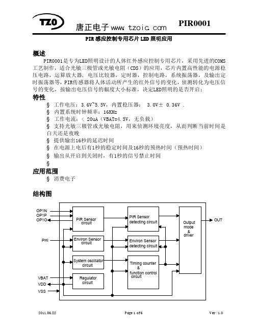
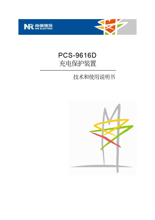

ZXLD137060V HIGH ACCURACY BUCK/BOOST/BUCK-BOOST LED DRIVER-CONTROLLER WITH AEC-Q100DescriptionThe ZXLD1370 is an LED driver controller IC for driving external MOSFETs to drive high current LEDs. It is a multi-topology controller enabling it to efficiently control the current through series connected LEDs. The multi-topology enables it to operate in buck, boost and buck-boost configurations.The 60V capability coupled with its multi-topology capability enables it to be used in a wide range of applications and drive in excess of 15 LEDs in series. The ZXLD1370 is a modified hysteretic controller using a patent pending control scheme providing high output current accuracy in all three modes of operation. High accuracy dimming is achieved through DC control and high frequency PWM control.The ZXLD1370 uses two pins for fault diagnosis. A flag output highlights a fault, while the multi-level status pin gives further information on the exact fault.Pin AssignmentsTSSOP-16EPCurve showing LED current vs. T LEDFeatures• 0.5% typical output current accuracy • 6 to 60V operating voltage range• LED driver supports Buck, Boost and Buck-boost • configurations• Wide dynamic range dimmingo 20:1 DC dimmingo 1000:1 dimming range at 500Hz • Up to 1MHz switching• High temperature control of LED current using TADJ • AEC-Q100 Grade 1• Available in “Green” Molding Compound (No Br, Sb)with lead Free Finish/ RoHS Compliant (Note 1)Note 1: EU Directive 2002/95/EC (RoHS). All applicable RoHS exemptionsapplied. Please visit our website at/products/lead_free.html .Typical Application CircuitBuck-boost diagram utilizing thermistor and TADJPin DescriptionsPin NamePinType (Note 2)DescriptionADJ 1 IAdjust input (for dc output current control) Connect to REF to set 100% output current.Drive with dc voltage (125mV<V ADJ < 2.5V) to adjust output current from 10% to 200% of set value. The ADJ pin has an internal clamp that limits the internal node to less than 3V. This provides some failsafe should they get overdriven REF 2 OInternal 1.25V reference voltage output TADJ 3 I Temperature Adjust input for LED thermal current controlConnect thermistor/resistor network to this pin to reduce output current above a presettemperature threshold.Connect to REF to disable thermal compensation function. (See section on thermal control.)SHP 4 I/O Shaping capacitor for feedback control loopConnect 100pF ±20% capacitor from this pin to ground to provide loop compensationSTATUS 5 O Operation status output (analog output)Pin is at 4.5V (nominal) during normal operation.Pin switches to a lower voltage to indicate specific operation warnings or faultconditions. (See section on STATUS output.) Status pin voltage is low during shutdown modeSGND 6 P Signal ground (Connect to 0V)PGND 7 P Power ground - Connect to 0V and pin 8 to maximize copper areaN/C 8 - Not Connected internally – recommend connection to pin 7, (PGND), to maximize PCBcopper for thermal dissipationN/C 9 Not Connected internally – recommend connection pin 10 (GATE) to permit wide coppertrace to gate of MOSFETGATE 10 O Gate drive output to external NMOS transistor – connect to pin 9V AUX 11 P Auxiliary positive supply to internal switch gate driverConnect to V IN , or auxiliary supply from 6V to 15V supply to reduce internal powerdissipation (Refer to application section for more details)Decouple to ground with capacitor close to device (refer to Applications section) V IN 12 P Input supply to device (6V to 60V)Decouple to ground with capacitor close to device (refer to Applications section)ISM 13 I Current monitor input. Connect current sense resistor between this pin and V INThe nominal voltage across the resistor is 225mVFLAG 14 O Flag open drain outputPin is high impedance during normal operationPin switches low to indicate a fault, or warning condition PWM 15 I Digital PWM output current controlPin driven either by open Drain or push-pull 3.3V or 5V logic levels.Drive with frequency higher than 100Hz to gate output ‘on’ and ‘off’ during dimmingcontrol.The device enters standby mode when PWM pin is driven with logic low level for more than 15ms nominal (Refer to application section for more details) GI 16 IGain setting inputUsed to set the device in Buck mode or Boost, Buck-boost modes Connect to ADJ in Buck mode operationFor Boost and Buck-boost modes, connect to resistive divider from ADJ to SGND. This defines the ratio of switch current to LED current (see application section). The GI pin has an internal clamp that limits the internal node to less than 3V. This provides some failsafe should they get overdrivenEP PAD P Exposed paddle. Connect to 0V plane for electrical and thermal managementNotes:2. Type refers to whether or not pin is an Input, Output, Input/Output or Power supply pin.Functional Block DiagramAbsolute Maximum Ratings (Voltages to GND Unless Otherwise Stated)Symbol Parameter Rating UnitV IN Input supply voltage relative to GND -0.3 to 65 VV AUX Auxiliary supply voltage relative to GND -0.3 to 65 VV ISM Current monitor input relative to GND -0.3 to 65 VV SENSE Current monitor sense voltage (V IN-V ISM) -0.3 to 5 VV GATE Gate driver output voltage -0.3 to 20 VI GATE Gate driver continuous output current 18 mAV FLAG Flag output voltage (Note 3) -0.3 to 40 VV PWM, V ADJ,V TADJ, V GI,V PWMOther input pins (Note 3) -0.3 to 5.5 VT J Maximum junction temperature 150 °CT ST Storage temperature -55 to 150 °CThese are stress ratings only. Operation outside the absolute maximum ratings may cause device failure.Operation at the absolute maximum rating for extended periods may reduce device reliability.Semiconductor devices are ESD sensitive and may be damaged by exposure to ESD events. Suitable ESD precautions should be taken when handling and transporting these devices.Package Thermal DataThermal Resistance Package Typical UnitJunction-to-Ambient, θJA (Note 4) TSSOP-16 EP 50 °C/WJunction-to-Case, θJC TSSOP-16 EP 23 °C/WRecommended Operating ConditionsSymbol Parameter Performance/Comment Min Max UnitV IN Input supply voltage range Normal operation 860 V Functional (Note 5) 6.3V AUX Auxiliary supply voltage range (Note 6) Normal operation 860 V Functional 6.3V ISM Current sense monitor input range 6.3 60 VV SENSE Differential input voltage V VIN-V ISM, with 0 ≤ V ADJ≤ 2.5 0 450 mVV ADJ External dc control voltage applied to ADJpin to adjust output currentDC brightness control modefrom 10% to 200%0.125 2.5 VI REF Reference external load current REF sourcing current 1 mAf max Recommended switching frequency range(Note 7)3001000kHzV TADJ Temperature adjustment (T ADJ) input voltagerangeV REF Vf PWM Recommended PWM dimming frequency range(Note 4)To achieve 1000:1 resolution 100 500 HzTo achieve 500:1 resolution 100 1000 Hzt PWMH/L PWM pulse width in dimming mode PWM input high or low 0.002 10 ms V PWMH PWM pin high level input voltage 2 5.5 V V PWML PWM pin low level input voltage 0 0.4 V T J Operating Junction Temperature Range -40 125 °C GI Gain setting ratio for boost and buck-boost modes Ratio= V GI/V ADJ0.200.50 Notes: 3.For correct operation SGND and PGND should always be connected together.4. Measured on High Effective Thermal Conductivity Test Board" according JESD51.5. The functional range of V IN is the voltage range over which the device will function. Output current and device parameters may deviate from theirnormal values for V IN and V AUX voltages between 6.3V and 8V, depending upon load and conditions.6.V AUX can be driven from a voltage higher than V IN to provide higher efficiency at low V IN voltages, but to avoid false operation; a voltage shouldElectrical Characteristics (Test conditions: V IN = V AUX = 12V, T A = 25°C, unless otherwise specified.)Symbol Parameter Conditions Min Typ Max Units Supply and reference parametersV UV-Under-Voltage detection thresholdNormal operation to switch disabledV IN or V AUX falling 5.2 5.6 6.3 VV UV+Under-Voltage detection thresholdSwitch disabled to normal operationV IN or V AUX rising 5.5 6 6.5 VI Q-IN Quiescent current into V IN PWM pin floating.Output not switching 1.5 3 mAI Q-AUX Quiescent current into V AUX 150300 µAI SB-IN Standby current into V IN. PWM pin groundedfor more than 15ms 90150 µAI SB-AUX Standby current into V AUX. 0.7 10 µA V REF Internal reference voltage No load 1.237 1.25 1.263VΔV REF Change in reference voltage with outputcurrentSourcing 1mA -5mVSinking 100 µA 5V REF_LINE Reference voltage line regulation V IN = V AUX , 6.5V<V IN = <60V -60 -90 dB V REF-TC Reference temperature coefficient +/-50 ppm/°C DC-DC converter parametersV ADJ External dc control voltage applied to ADJpin to adjust output current (Note 8)DC brightness control mode10% to 200%0.125 1.25 2.5 VI ADJ ADJ input current (Note 8) V ADJ ≤ 2.5VV ADJ= 5.0V†1005nAµAV GI GI Voltage threshold for boost and buck-boost modes selection (Note 8) V ADJ = 1.25V0.8 VI GI GI input current (Note 8) V GI ≤ 2.5VV GI= 5.0V†1005nAµAI PWM PWM input current V PWM = 5.5V 36100 µAt PWMoff PWM pulse width(to enter shutdown state)PWM input low 10 15 25 msT SDH Thermal shutdown upper threshold(GATE output forced low)Temperature rising. 150 ºCT SDL Thermal shutdown lower threshold(GATE output re-enabled)Temperature falling. 125 ºCHigh-Side Current Monitor (Pin ISM)I ISM Input Current Measured into ISM pin andV ISM = 12V11 20 µAV SENSE_acc Accuracy of nominal V SENSE thresholdvoltage V ADJ = 1.25V±0.25±2 %V SENSE-OC Over-current sense threshold voltage 300 350 375 mV Notes:8. The ADJ and GI pins have an internal clamp that limits the internal node to less than 3V. This provides some failsafe should those pins get overdriven.Electrical Characteristics (Continued) (Test conditions: V IN = V AUX = 12V, T A = 25°C, unless otherwise specified.)Symbol Parameter Conditions Min Typ Max UnitsOutput ParametersV FLAGL FLAG pin low level output voltage Outputsinking 1mA 0.5 VI FLAGOFF FLAG pin open-drain leakage current V FLAG =40V1 µA V STATUS STATUS Flag no-load output voltage(Note 9)Normal operation4.2 4.5 4.8 VOut of regulation (V SHP out of range)(Note 10)3.3 3.6 3.9 V IN under-voltage (V IN < 5.6V) 3.3 3.6 3.9Switch stalled (t ON or t OFF > 100µs) 3.3 3.6 3.9 Over-temperature (T J > 125°C) 1.5 1.8 2.1 Excess sense resistor current (V SENSE > 0.32V)0.6 0.9 1.2 R STATUS Output impedance of STATUS output Normal operation10k ΩDriver output (PIN GATE)V GATEH High level output voltage No load Sourcing 1mA(Note 11) 10 11 V V GATEL Low level output voltage Sinking 1mA, (Note 12)0.5VV GATECL High level GATE CLAMP voltageV IN = V AU X = V ISM = 18V I GATE = 1mA12.8 15 V I GATE Dynamic peak current available duringrise or fall of output voltage Charging or discharging gate ofexternal switch with Q G = 10nC and400kHz±300 mAt STALL Time to assert ‘STALL’ flag andwarning on STATUS output(Note 13)GATE low or high 100 170 µsLED Thermal control circuit (T ADJ ) parametersV TADJHUpper threshold voltageOnset of output current reduction (V TADJ falling)560 625 690 mV V TADJL Lower threshold voltageOutput current reduced to <10% of set value (V TADJ falling)380 440 500 mV I TADJ T ADJ pin Input current V TADJ = 1.25V1 µANotes: 9. In the event of more than one fault/warning condition occurring, the higher priority condition will take precedence. E.g. ‘Excessive coil current’ and‘Out of regulation’ occurring together will produce an output of 0.9V on the STATUS pin. The voltage levels on the STATUS output assume the Internal regulator to be in regulation and V ADJ <=V REF . A reduction of the voltage on the STATUS pin will occur when the voltage on V IN is near the minimum value of 6V.10. Flag is asserted if V SHP <2.5V or V SHP >3.5V11. GATE is switched to the supply voltage V AUX for low values of V AUX (i.e. between 6V and approximately 12V). For V AUX >12V, GATE is clamped internally to prevent it exceeding 15V.12. GATE is switched to PGND by an NMOS transistor13. If t ON exceeds t STALL , the device will force GATE low to turn off the external switch and then initiate a restart cycle. During this phase, ADJ is grounded internally and the SHP pin is switched to its nominal operating voltage, before operation is allowed to resume. Restart cycles will berepeated automatically until the operating conditions are such that normal operation can be sustained. If t OFF exceeds t STALL , the switch will remain off until normal operation is possible.Typical Characteristics – Buck Mode – R S = 150m Ω – L = 33µH - I LED = 1.5AInput Voltage (V)Figure 1: Load Current vs. Input Voltage & Number of LEDL E D C u r r e n t (A )01002003004005006007008009001000Input Voltage (V)Figure 2: Frequency vs. Input Voltage & Number of LEDS w i t c h i n g F r e q u e n c y (k H z )6.51115.52024.52933.53842.54751.55660.5E f f i c i e n c yTypical Characteristics – Buck Mode – Rs = 300m Ω - L = 47µH - I LED = 750mA0.7150.7200.7250.7300.7350.7406.51115.52024.52933.53842.54751.55660.5Input Voltage (V)Figure 4: I vs. Input & Number of LEDLEDL E D C u r r e n t (A )01002003004005006007008009001000Input Voltage (V)Figure 5: Frequency ZXLD1370 - Buck Mode - L47HμS w i t c h i n g F r e q u e n c y (k H z )6.51115.52024.52933.53842.54751.55660.5E f f i c i e n c yTypical Characteristics – Boost mode – I LED = 350mA – R S = 150m Ω – GI RATIO = 0.230.0000.0500.1000.1500.2000.2500.3000.3500.4006.51013.51720.52427.53134.53841.54548.5Input Voltage (V)Figure 7: I vs. Input V oltage & Number of LEDLEDL E D C u r r e n t (A )50100150200250300350400450500Input Voltage (V)Figure 8: Frequency vs. Input Voltage & Number of LEDS w i t c h i n g F r e q u e n c y (k H z )60%65%70%75%80%85%90%95%E f f i c i e n c yTypical Characteristics – Buck-Boost mode – R S =150m Ω - I LED = 350mA - GI RATIO = 0.230.3300.3350.3400.3450.3500.3550.3600.3650.370Input Voltage (V)Figure 10: LED Current vs. Input Voltage & Number of LEDL E D C u r r e n t (A )6.589.51112.51415.517Input Voltage (V)Figure 11: Switching Frequency vs. Input Voltage & Number of LEDS w i t c h i n g F r e q u e n c y (k H z )60%65%70%75%80%85%90%95%6.589.51112.51415.517E f f i c i e n c y分销商库存信息: DIODESZXLD1370EST16TC。

GED1963系列——低压差线性稳压器1.产品特性◆输出电流:1.5A◆压差电压:300mV◆低噪声:40μV RMS◆1mA的静态电流◆无需保护二极管◆固定输出电压:1.5V、1.8V、2.5V、3.3V◆可调输出电压:1.33V to 20V◆电池反接保护◆无反向电流◆过热保护◆塑封3-Lead SOT-223,8-Lead SO◆可兼容LT1963系列产品◆工作温度范围:-40℃~125℃◆质量等级:工业级(I)2.产品应用◆提供逻辑电源◆开关电源的后置稳压器3.产品概述GED1963电路是低压差稳压器,用于产生一个稳定电压源,固定输出 1.5V、1.8V、2.5V、3.3V,可调输出电压 1.33V-20V,压差电压为300mV时可提供 1.5A的电流,静态工作电流小于1mA。
GED1963可使用最小10uF的输出电容,芯片具有电池反接保护、过流保护、过热保护和电流反接保护等特性。
GED1963采用SOT-223和8-Lead SO塑料封装。
4.典型应用图4-1 GED1963系列的典型应用电路C1为输入电容,一般使用10uF陶瓷电容,C2为输出电容,一般使用10uF钽电容,若使用陶瓷电容需要增加相应的ESR电阻,详见9.3节。
5.绝对最大额定值IN脚电压……………………………………………………………………………±20VOUT脚电压…………………………………………………………………………-0.6V,20V输入输出压差…………………………………………………………………………±20VADJ脚电压…………………………………………………………………………±7VSHDN脚电压………………………………………………………………………±20V工作结温范围(注2)………………………………………………………………-40℃~+125℃储存温度范围…………………………………………………………………………-65℃~+150℃引脚温度(焊接,10秒)……………………………………………………………300℃注1:列表中数值是绝对最大额定值,任何超过这些值的情况,可能对器件造成永久损害。

技术文件技术文件名称:PDC401NRV0R技术文件编号:JS00429A版本:A/0共 13 页(包括封面)拟制审核标准化批准南京丙鼎电子有限公司1.显示指标32.极限参数33.直流特性34.光电特性45.管脚连接46.编码表47.外观要求58.质量保证109.LCD模块使用注意事项131.显示指标显示像素:4个七段8字+4个圆点+1个冒号可视区域:36.8(W)×16.3(H)毫米外型尺寸:最大60(W)×35.5(H)×10(T)毫米LCD类型:TN显示模式:反射式、正显示视角:6:00点钟控制/驱动芯片:KS0065温度范围:工作-30℃~+70℃存储- 40℃~+75℃模块工作电压:5V.背光源工作电压:5V2.极限参数2.1电压及温度极限参数注意(1)T a= 0°C :最大50Hr(2)T a≤40°C :最大90%RHT a≥40°C :绝对湿度必须低于40°C、90%RH下的湿度。
3.直流特性4.光电特性4.1 TN屏体光电特性5.管脚连接6.编码表7.外观要求7.1检查项目7.2 判定标准8.质量保证8.1 测试条件8.1.1 温度和湿度(环境温度)温度:20±5℃湿度:65±5%RH8.1.2 测试频率单循环区注意1:常温下恢复4小时注意2:观察时无露水凝结注意3:各项试验后,在规定测试条件下模块能正常工作。
8.1.4 试验条件低温运行:-30℃持续时间:4h高温运行:+70℃持续时间:4h高温存贮:+75℃持续时间:4h恢复时间:2h低温存贮:-40℃持续时间:4h恢复时间:2h恒定湿热:+35℃湿度:93%+2%/-3%持续时间48h高低温冲击:表2 温度冲击条件跌落:整机做跌落试验,按照整机跌落试验的条件进行。
8.2 试验内容LCD测试:测试时,笔划有无多缺、颜色是否均匀、对比度是否良好。

504PDT Connectorized PIN Photodiode SpecificationsAbsolute Maximum RatingsAbsolute maximum limits mean that no catastrophic damage will occur if the product is subjected to these ratings for short periods, provided each limiting parameter is in isolation and all other parameters have values within the performance specification. It should not be assumed that limiting values of more than one parameter can be applied to the product at the same time.Parameter Symbol Minimum Maximum Units Reverse Voltage Vr–20VReverse Current Ir–12mAForward Voltage Vf–1VForward Current If–5mAPower Dissipation––50mWOperating Temperature Tc-4085°CStorage Temperature Ts-4085°CSoldering–10 seconds––260°C Performance Specification505506ALL DIMENSIONS IN mm.DIMENSION MIN.MAX.A B C ∅D E ∅F ∅G H ––––12.00.41 M8 X 0.7513.3519.59.5159.1–0.4713.55DIMENSION MIN.MAX.∅J L M N P ∅Q ∅R 2.08–––– 2.54 NOM.– 2.321.652.26.88.24.2ALL DIMENSIONS IN mm.PDT Mechanical Outline OptionsPDT0X1X-FC-APDT0X1X-SC-A Plastic HousingDIMENSION MIN.MAX.A B C D E F G H–1.8–––9.433/8-32 UNEF-2A2-56UNC-2B21.02.29.812.99.79.63DIMENSION MIN.MAX.J∅K∅LM∅NPQR12.00.41––2.54 NOM.14.92.54 NOM.0.50 NOM.–0.477.022.515.3ALL DIMENSIONS IN mm.PDT Electrical PinoutsPDT Mechanical Outline OptionsPDT1X4X-ST-FPIN 1: CATHODE +VEPIN 2: ANODE -VEPIN 3: TO CASEPDT0X11PIN 1: ANODE -VEPIN 2: CATHODE +VEPIN 3: TO CASEPDT0X12PIN 1: CATHODE +VEPIN 2: TO CASEPIN 3: ANODE -VEPDT0X16PIN 1: ANODE -VEPIN 2: CATHODE +VEPIN 3: TO CASEPDT0X17507Ordering InformationPDT0X1X-XX-XFlange Type:A = 2 hole panel mountF = 2 hole PCB mount, threadedConnector Type:FPST®SCPin Out:Options shown on page 4Photodiode Diameter:3 = 50 µm4 = 90 µmPreferred Options:PDT0311-FC-APDT0312-FC-APDT0411-FC-APDT0411-ST-FPDT0412-FC-APDT0412-ST-FPDT0417-FC-AAdditional copies are available to meet your specific needs. Please contact your local representative for details. Handling Precautions1. The PDT0X1X can be damagedby current surges ofovervoltage. Power supplytransient precautions shouldbe taken.2. Normal handling precautionsfor electrostatic sensitivedevices should be taken.ST® is a Registered Trademark of AT&T.508。
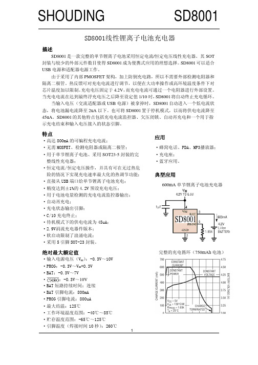
SD8001SD8001SD8001SD8001SD8001 SD8001SD8001SD8001线性锂离子电池充电器描述是一款完整的单节锂离子电池采用恒定电流/恒定电压线性充电器。
其SOT 封装与较少的外部元件数目使得成为便携式应用的理想选择。
可以适合USB电源和适配器电源工作。
由于采用了内部PMOSFET架构,加上防倒充电路,所以不需要外部检测电阻器和隔离二极管。
热反馈可对充电电流进行调节,以便在大功率操作或高环境温度条件下对芯片温度加以限制。
充电电压固定于4.2V,而充电电流可通过一个电阻器进行外部设置。
当充电电流在达到最终浮充电压之后降至设定值1/10时,将自动终止充电循环。
当输入电压(交流适配器或USB电源)被拿掉时,自动进入一个低电流状态,将电池漏电流降至2uA以下。
也可将置于停机模式,以而将供电电流降至45uA。
的其他特点包括充电电流监控器、欠压闭锁、自动再充电和一个用于指示充电结束和输入电压接入的状态引脚。
特点·高达800mA的可编程充电电流;·无需MOSFET、检测电阻器或隔离二极管;·用于单节锂离子电池、采用SOT23-5封装的完整线性充电器;·恒定电流/恒定电压操作,并具有可在无过热危险的情况下实现充电速率最大化的热调节功能;·直接从USB端口给单节锂离子电池充电;·精度达到±1%的4.2V预设充电电压;·用于电池电量检测的充电电流监控器输出; ·自动再充电;·充电状态输出引脚;·C/10充电终止;·待机模式下的供电电流为45uA;·2.9V涓流充电器件版本;·软启动限制了浪涌电流;·采用5引脚SOT-23封装。
应用·蜂窝电话、PDA、MP3播放器; ·充电座;·蓝牙应用。
典型应用典型应用600mA单节锂离子电池充电器完整的充电循环(750mAh电池)绝对最大额定值·输入电源电压(V CC):-0.3V~10V ·PROG:-0.3V~V CC+0.3V·BAT:-0.3V~7V·:-0.3V~10V·BAT短路持续时间:连续·BAT引脚电流:800mA·PROG引脚电流:800uA·最大结温:125℃·工作环境温度范围:-40℃~85℃ ·贮存温度范围:-65℃~125℃ ·引脚温度(焊接时间10秒):260℃SD8001 1电特性凡表注●表示该指标适合整个工作温度范围,否则仅指T A=25℃,V CC=5V,除非特别注明。
PD系列(LCD)多功能网络(谐波)电力仪表用户手册施瑞德电气有限公司目录1.产品特点 (3)2.仪表型号 (3)3。
型号说明 (4)4.主要技术参数 (5)5.面板说明及信息 (6)6。
操作流程 (10)7.操作说明 (13)8。
输出功能 (15)9。
通信协议 (16)10。
外形及安装开口尺寸 (20)11。
接线图 (21)一、产品特点⊙测量项目:电压/电流/有功功率/无功功率/频率/功率因率/四象电能等,共28个电参数⊙4路开关量输入和4路开关量输出;输入/输出全隔离⊙具有效值测量;⊙具有可编程变送输出功能,可对电压/电流/有功功率/无功功率/频率/功率因数变送输出⊙具有RS485数字接口,采用Modbus RTU通信协议⊙具有二路电能脉冲输出;四路可编程报警;显示编程设置输入参数⊙对有功电度/无功电度具有掉电保护功能⊙具有2-31次谐波测量功能⊙具有需量测量功能⊙具有8时段4费率功能;该系列仪表可广泛应用于控制系统、SCADA系统和能源管理系统中、变电站自动化、配电网自动化、小区电力监控、工业自动化、智能建筑、智能型配电盘、开关柜中;有安装方便、接线简单、维护方便、工程量小、现场可编程设置输入参数的特点。
警告如果不按说明书操作会发生意外,而且会导致产品毁坏。
二、仪表型号1、PD系列系列多功能电力仪表是针对电力系统、工矿企业、公共设施、智能大厦等电力监控、智能控制、计量考核的应用场合设计的高精度、高可靠、高性价比的智能配电仪表产品.该系列仪表采用高可靠的MCU设计,可以测量三相电网中所有电量参数如三相电压(相/线)、三相电流、有功功率、无功功率、功率因数、电网频率、需量和双向电能计量,具有标准电能脉冲输出和RS485通讯接口,可选多种扩展功能模块.2、PD系列系列(LCD显示)为标准产品,具有测量和计量功能,配置电能脉冲输出和通讯接口;PD系列系列(LCD显示)在标准功能的基础上增加直流变送输出、开关输入监测、继电器输出等功能;PD系列系列(LCD显示)采用段码式液晶屏菜单切换显示,并具有复费率电能计量和谐波测量等功能;外形代号指针表型号面框尺寸开孔尺寸2 42方形120*120 111*1119 96方形96*96 91*913 80方形80*80 76*76A 72方形72*72 67*67四:主要技术参数网络三相三线、三相四线电压额定值AC 100V、400V(订货时请说明)电压过负荷持续:1。
尊敬的顾客感谢您使用本公司ETFA-V互感器伏安变比极性综合测试仪。
在您初次使用该仪器前,请您详细地阅读本使用说明书,将可帮助您熟练地使用本仪器。
我们的宗旨是不断地改进和完善公司的产品,因此您所使用的仪器可能与使用说明书有少许的差别。
如果有改动的话,我们会用附页方式告知,敬请谅解!您有不清楚之处,请与公司售后服务部联络,我们定会满足您的要求。
由于输入输出端子、测试柱等均有可能带电压,您在插拔测试线、电源插座时,会产生电火花,小心电击,避免触电危险,注意人身安全!◆慎重保证本公司生产的产品,在发货之日起三个月内,如产品出现缺陷,实行包换。
一年(包括一年)内如产品出现缺陷,实行免费维修。
一年以上如产品出现缺陷,实行有偿终身维修。
如有合同约定的除外。
◆安全要求请阅读下列安全注意事项,以免人身伤害,并防止本产品或与其相连接的任何其它产品受到损坏。
为了避免可能发生的危险,本产品只可在规定的范围内使用。
只有合格的技术人员才可执行维修。
—防止火灾或人身伤害使用适当的电源线。
只可使用本产品专用、并且符合本产品规格的电源线。
正确地连接和断开。
当测试导线与带电端子连接时,请勿随意连接或断开测试导线。
产品接地。
本产品除通过电源线接地导线接地外,产品外壳的接地柱必须接地。
为了防止电击,接地导体必须与地面相连。
在与本产品输入或输出终端连接前,应确保本产品已正确接地。
注意所有终端的额定值。
为了防止火灾或电击危险,请注意本产品的所有额定值和标记。
在对本产品进行连接之前,请阅读本产品使用说明书,以便进一步了解有关额定值的信息。
·请勿在无仪器盖板时操作。
如盖板或面板已卸下,请勿操作本产品。
使用适当的保险丝。
只可使用符合本产品规定类型和额定值的保险丝。
避免接触裸露电路和带电金属。
产品有电时,请勿触摸裸露的接点和部位。
在有可疑的故障时,请勿操作。
如怀疑本产品有损坏,请本公司维修人员进行检查,切勿继续操作。
请勿在潮湿环境下操作。
FEATURES DESCRIPTION APPLICATIONS
• Visible light response • Sintered construction • Low cost
SYMBOL PARAMETER MIN MAX UNITS V pk Applied Voltage 150 V P d Δpo/Δt Continuous Power Dissipation
100 mW/°C T O
Operating and Storage Temperature -30
+75 °C T S Soldering Temperature*
+260
°C
SYMBOL CHARACTERISTIC TEST CONDITIONS MIN TYP MAX UNITS R D Dark Resistance After 10 sec. @ 10 Lux @ 2856 °K 0.2
M W R I Illuminated Resistance 10 Lux @ 2856 °K
3 11
K W S Sensitivity
LOG(R100)-LOG(R10)** LOG(E100)-LOG(E10)***
0.6
W/Lux l range Spectral Application Range Flooded 400 700
nm l peak Spectral Application Range Flooded
520 nm t r Rise Time 10 Lux @ 2856 °K 55 ms T f
Fall Time After 10 Lux @ 2856 °K 20
ms
CdS Photoconductive Photocells
PDV-P8001
The PDV-P8001 are (CdS), Photoconductive
photocells designed to sense light from 400 to 700 nm. These light dependent resistors are available in a wide range of resistance values. They’re packaged in a two leaded plastic-coated ceramic header.
• Camera exposure • Shutter controls • Night light Controls
* 0.200 inch from base for 3 seconds with heat sink.
ELECTRO-OPTICAL CHARACTERISTICS RATING (TA)=23°C UNLESS OTHERWISE NOTED **R100, R10: cell resistances at 100 Lux and 10 Lux at 2856 °K respectively .
***E100, E10: luminances at 100 Lux and 10 Lux 2856 °K respectively.
Information in this technical datasheet is believed to be correct and reliable. However, no responsibility is assumed for possible inaccuracies or omission. Specifications are subject to change without notice. REV 3/30/06
ABSOLUTE MAXIMUM RATING (TA)=23°C UNLESS OTHERWISE NOTED
/
分销商库存信息: ADVANCED-PHOTONIX PDV-P8001。