LBT-B01使用说明
- 格式:pdf
- 大小:294.60 KB
- 文档页数:2

博立多媒体保安相机欢迎您选购博立多媒体通讯(亚洲)有限公司保安相机。
为了保护您的投资、充分发挥本保安相机的功能,请在使用之前详细阅读本说明书。
操作更简单★功能更强★处理更快目录一、产品简介 (3)1 功能介绍 (3)2 应用场合 (3)3 外观及各部件介绍 (3)4 存储图片或视频 (5)二、注意事项 (6)三、快速入门 (7)1 接通电源 (7)2 开机 (8)3 手动拍照 (8)4 监控 (8)5 回放照片 (9)6 录制视频 (9)7 关机 (10)四、高级操作 (11)1 相关参数的设置 (11)1)设置相机模式 (11)2)格式化SD卡 (12)3)设置照片分辨率 (13)4)设置视频分辨率 (13)5)设置日期时间 (14)6)设置连拍模式 (16)7)设置视频剪辑长度 (17)8)设置监控间隔时间 (18)9)设置感应灵敏度 (19)10)设置时间戳 (19)11)设置定时器 (20)12)恢复出厂设置 (22)2 回放与删除照片(或视频) (23)1)回放照片 (23)2)删除照片(或视频) (23)3 智能监控 (24)4 感应角度和距离测试 (24)5 文件系统 (24)6 文件格式 (24)7 安装驱动程序 (24)8 固件升级 (25)9 初始设置 (25)五、安装说明 (26)联系我们 (27)附件:各参数指标一览表 (28)一、产品简介1 功能介绍博立多媒体通讯(亚洲)有限公司保安相机采用红外低误报自动人体(动物)感应技术,自动拍摄高清晰度(500万像素)的图片或流畅的视频。
保安相机在未探测到人体(动物)时处于节能状态,耗电仅200微安,可以长时间处于警戒状态,使用8节五号碱性电池最长可以达到6个月左右的待机时间。
一旦有人体(动物)进入探测区域时,其摄像拍照功能将立即启动(启动时间为1秒钟)拍摄照片或视频。
每款机器均自带红外线照明,特殊的CMOS感光芯片可在全黑夜间使用红外拍摄获得清晰的黑白图像或视频;光线足够时拍摄彩色照片或摄像。

新表处于关机状态,按任意键启动(除了背光灯键)1.0 介绍● 感谢购买本手表。
手表具有能测量和显示户外状况的电子传感器:天气预报、温度、气压、高度和罗盘方向。
● 为你的徒步旅行、野营或其它户外活动(特别是长时间的)提供必要信息。
● 同时手表也包括时间、闹钟、秒表、倒计时、测步计和双时区功能。
● 手表经过精心的设计和生产适合于户外活动。
为了充分利用这些功能,使用前建议遵循以下事项:● 使用手表前请仔细阅读说明书。
● 避免手表暴露在极端条件下。
● 避免用力使用或重压手表。
● 请不要自行打开手表的后盖,因为设备包含精密的电子传感器和元件。
● 经常用软布清洁设备以达到更长的寿命。
● 手表请远离含有磁性元件的磁铁或设备,如手机、扬声器或马达。
● 手表不使用时,请放置在干燥的地方。
2.0 按键介绍3.0 主要功能模式手表共有9大模式:时间模式、闹钟模式、秒表模式、倒计时模式、测步计模式、双时区模式、高度计模式、气压计模式、数字罗盘。
按模式键切换时间菜单,按传感器键切换传感器菜单,长按传感器键从传感器菜单切换到时间菜单。
如下图所示: 4.0 时间模式-功能显示 功能显示● 时间模式包括4种功能显示:星期、温度、高度变化趋势图、海平面气压变化趋势图。
● 首行:按键切换显示星期、温度、高度变化趋势图和海平面气压变化趋势图● 中间:时间● 底行:日期自动切换● 长按键激活自动切换功能,当长按住键,4种功能会逐个显示。
4.1时间模式-天气预报 天气预报● 预测未来天气是手表的一个特殊功能。
通过分析过去大气压变化来预测。
如何预测未来天气● 手表提供4种符号代表不同天气模式键(Mode )切换时间、闹钟、秒表、倒计时、测步计和双时区模式在设定模式下选择设定项目传感键(Sensor ) 切换显示高度计、气压计和罗盘模式 开始/暂停键(Start/Stop) 在同一模式下,切换显示功能在秒表、倒计时和测步计模式下,按此键开始/暂停计时/测步 设置数字时的数值增加键; 切换Yes/No圈数/重置键(Lap/Reset )在秒表模式下,按此键记录圈数或重置计时的功能; 将光标向左移动显示历史数据; 设置数字时的数值减少键;切换Yes/No 背光灯键(Light )启动背光灯约3秒·晴天(Sunny )·晴间多云(Cloudy with Sun ) ·多云(Cloudy ) ·下雨(Raining )注意:由于手表通过大气压变化来预测未来天气,当使用者在同一个地方至少24小时所得的结果会更加准确。

波茵B一001温控器说明书温控器说明书:1.按▲(上键)和▼(下键)按2下,在画面闪动的时候,按▲或▼,可设定希望的温度。
2.偏差温度设定(设定温度与启动温度,温差设定)(上键)与▼(下键)同时按3秒会显示“d1F”字母,按,或▼可以调节温差3.温度矫正方法先按▲,再按电源,3秒后会显示“Cor”继续按3秒会校正为0.0℃(出厂设定为0.0℃,设定范围为士10℃)4.特殊功能调节先▼(下键)按往不动,再按电源,会显示“ty2”继续按3秒,可设定所有的功能,每按一次电源,会显示各种菜单。
“ty2”为温感线感应温度。
5.时段供电温度调节方式按▲(上键),会显示“stp”继续按3秒,会显示1-5时段显示,出厂1档,设定范围0-5挡6.定时关机设定方法(下键)按住3秒钟,显示“t_t”继续按3秒,在“too状态,可设定定时关机功能,设定时间范围0-99个小时。
设定时间内正常工作,到了时间自自动关机(出厂设定为0时)如显示“to9”9个小时就会自动关机,设定关机时间,会显显示剩下多少时间,剩余时间显示“t11”就是剩11小时,“t8.5”就剩余8个小时50分钟。
定定时,时间的变动,关机重启的话变成“0”操作说明:1、将温控器接入电源中,温控器的电源红灯亮时表示停机的指示,绿灯是开机的指示。
2、将冰箱的插头插在温控器的输出插孔中,同时将冰箱内部的内温控制器开到最大的文职。
3、在温控器上的按钮是用来设定开、停时间使用的,用户可根据自己的需要进行设置。
冰箱温控器的档位可以根据季节温度变化来调整,春秋季应调在中间的档位处(3档左右),夏季应调低一些(1-2档),而冬季数字应适当调大一些,保持冷冻室的温度在零下18度左右,冷藏室的温度在0-10度之间,最好是在4-8度之间。
打开冰箱我们就可以看到一个旋转按钮,上面刻有数字,一般冰箱的控制是在0到7档之间。
家用中常见的是5档,不会存在6档和7档的制冷档位,数字越大,冷冻室里的温控越底。

Step 29. Enable Alarm 1 SubmenuIf flashing ENBL is displayed, press a , if DSBL is displayed,press b until ENBL is displayed, then press d to store and go to the next menu item.Step 30. Select the Deviation Control Type Submenu Press d . If flashing _DEV Deviation is displayed press a ,otherwise press b until flashing _DEV is shown. Now press d to store and go to next menu item.Step 31. Select the Latched Type SubmenuPress d . If flashing UNLT Unlatched is displayed press a ,otherwise press b until UNLT is displayed.Press d to store and advance to next menu item.Step 32. Select the Normally Open Type of Contact Closure SubmenuPress d . If flashing N.o.Normally Open is displayed,press a , otherwise press b until N.o.is displayed. Press d to store and advance to next menu item.Step 33. Select the Above Type of Active Submenu Press d . If flashing ABoV Above is displayed, press a ,otherwise press b until ABoV is displayed. Press d to store and advance to next menu item.Step 34. Enable Alarm 1 at Power On (A.P.oN )Press d . If flashing ENBL is displayed, press a , otherwise press b until ENBL is displayed. Press d to store and advance to next menu item.Step 35. Enter Alarm 1 High SubmenuPress a twice to skip ALR.L Alarm 1 Low value. ALR.L is for below & ALR.H for above.Step 36. Set the Alarm 1 High value (ALR.H )Press d . Press b or c until value to set the display to 002.0. Press d to save.Step 37. Enter the Alarm 2 MenuThe display will show ALR2the top menu for Alarm 2.Repeat steps from 28 to 36 to set for Alarm 2 the same conditions as for Alarm 1.Step 38. Configuration of Display Color Selection Press a until the COLR Display Color Selection Menu appears on the Display. Configure COLR as N.CLR / GRN (green), 1.CLR / RED (red), 2.CLR / AMBR (amber). Please refer to the operator’s manual if needed.Step 39. Run a TestPress a until reset the controller and return to RUN Mode to display 075.0(Ambient Temperature). Now you are ready to observe temperature as it rises 10°F higher than displayed. Touch the tip of the Thermocouple to raise the temperature above the Alarm 2 High value 082.0, and AL2will turn on, and Display Color will change from Green to Amber. Continue touching the tip to raise the temperature above the Alarm 1 High value 087.0and Display Color will change from Amber to Red.Step 10. Enter to the Thermocouple Input Submenu Press d to store Thermocouple Input. The display will stop flashing and show the top menu for Thermocouple types. If you press a controller will step to next menu item (Skip to Step 14).Step 11. Enter to the Thermocouple Type Input Submenu Press d to display flashing, previously selected Thermocouple type.Step 12. Scroll through available selection of TC types Press b to sequence thru flashing Thermocouple types,(select k -for type "K" CHROMEGA ®/ALOMEGA ®)J K T E N DIN J R S B C - TC types J k t E N dN J R S b C - DisplayStep 13. Store TC typeAfter you have selected the Thermocouple type press d to store your selection, the instrument automatically advances to the next menu item.Step 14. Enter to Reading Configuration MenuThe display shows RDG Reading Configuration, which is the top menu for 4 submenus: Decimal Point, Degree Units,Filter Constant and Input/Reading Submenus.Step 15. Enter to Decimal Point Submenu Press d to show DEC Decimal Point.Step 16. Display the Decimal Point positionPress d again to display the flashing Decimal Point position.Step 17. Select the Decimal Point position Press b to select FFF.F Decimal Point position.Step 18. Store selected Decimal Point positionBy pressing d momentarily the Decimal Point position will be stored and the instrument will go to the next menu item.Step 19. Enter to Temperature Unit Submenu Display shows TEMP Temperature Unit.Step 20. Display available Temperature Units Press d to display the flashing Degree °F or °C .Step 21. Scroll through Temperature Units selection Press b to select °F Degree.Step 22. Store the Temperature UnitPress d to display momentarily that the Degree Unit has been stored and the instrument will go automatically to the next menu item.Step 23. Enter the Filter Constant Submenu Display shows FLTR Filter Constant Submenu.Step 24. Display the Filter Constant Value Submenu Press d to display the flashing, previously selected Filter Constant.Step 25. Scroll through available Filter Constants Press b to sequence thru Filter Constants 0001, 0002,0004, 0008, 0016, 0032, 0064and 0128.Step 26. Store the Filter ConstantPress d momentarily to store 0004Filter Constant and the instrument will automatically go to the next menu item.Step 27. Enter Alarm 1 MenuThe display will show ALR1the top menu for Alarm 1. In the following steps we are going to enable Alarm 1, Deviation,Unlatch, Normally Open, Active Above, Enable at power on and +2°F High Alarm i.e. Process Value > Setpoint 1 Value +2°F will activate Alarm 1.Step 28. Enter Alarm 1 Enable/Disable Submenu Press d to display flashing DSBL / ENBL .USAMQS3448/0406It is the policy of OMEGA to comply with all worldwide safety and EMC/EMI regulations that apply.OEMGA is constantly pursuing certification of its products to the European New Approach Directives.OMEGA will add the CE mark to every appropriate device upon certification.The information contained in this document is believed to be correct, but OMEGA Engineering,Inc.accepts no liability for any errors it contains, and reserves the right to alter specifications without notice.TRADEMARK NOTICE:®,®,, andare Trademarks ofOMEGA ENGINEERING, INC.®SPECIFICATIONAccuracy:+0.5°C temp;0.03% rdg. process typical Resolution:1°/0.1°; 10 µV process Temperature Stability:0.04°C/°C RTD;0.05°C/°C TC @ 25°C (77°F); 50 ppm/°C process Display:4-digits, 9-segments LED,10.2 mm (0.40") with red, green and amber programmable colors Input Types:Thermocouple, RTD, Analog Voltage and Current TC:(ITS90)J, K, T, E, R, S, B, C, N, L RTD:(ITS68)100/500/1000 ohm Pt sensor2-, 3-, or 4-wire; 0.00385 or 0.00392curve Voltage:0 to 100 mV, 0 to 1 V, 0 to 10 Vdc Current:0 to 20 mA (4 to 20 mA)Output 1†:Relay 250 Vac @ 3 A Resistive Load,SSR, Pulse Output 2†:Relay 250 Vac @ 3 A Resistive Load,SSR, Pulse †Only with -AL Limit Alarm optionOptions:Communication:RS-232 / RS-422 / RS-485 or Excitation:24 Vdc @ 25 mAExc. not available for Low Power OptionLine Voltage/Power:90 - 240 Vac ±10%,50 - 400 Hz*, or 110 - 375 Vdc, 4 W* No CE compliance above 60 HzLow Voltage Power Option:12 - 36 Vdc, 3 W****Units can be powered safely with 24 Vac but No Certification for CE/UL are claimed.Dimensions:25.4 H x 48 W x 126.3 D mm (1.0 x 1.89 x 5")Weight:127 g (0.28 lb)Approvals:UL, C-UL, CE per EN 61010-1:2001This Quick Start Reference provides informationon setting up your instrument for basic operation.The latest complete Communication and OperationalManual as well as free Software and ActiveX Controlsare available at /specs/iseries or onthe CD-ROM enclosed with your shipment. SAFETY CONSIDERATIONThe instrument is a panel mount device protected in accordance with EN 61010-1:2001, electrical safety requirements for electrical equipment for measurement, control and laboratory. Remember that the unit has no power-on switch. Building installation should include a switch or circuit-breaker that must be compliant to IEC 947-1 and 947-3. SAFETY:•Do not exceed voltage rating on the label located onthe top of the instrument housing.•Always disconnect power before changing signal andpower connections.•Do not use this instrument on a work bench withoutits case for safety reasons.•Do not operate this instrument in flammable orexplosive atmospheres.•Do not expose this instrument to rain or moisture. EMC:•Whenever EMC is an issue, always use shielded cables.•Never run signal and power wires in the same conduit.•Use signal wire connections with twisted-pair cables.•Install Ferrite Bead(s) on signal wire close to theinstrument if EMC problems persist.Panel Mounting Instruction:ing the dimensions from the panel cutout diagramshown above, cut an opening in the panel.2.Insert the unit into the opening from the front of thepanel, so the gasket seals between the bezel and thefront of the panel.3.Slide the retainer over the rear of the case and tightenagainst the backside of the mounting panel.。

用户使用手册User Guide自动栏杆机Intelligent Barriers克立司帝控制系统(上海)股份有限公司Crest Control System(Shanghai)Co.,Ltd.安全说明1、版权通知Granity《用户使用手册》中所刊登之产品图片因摄影及印刷之故可能与实际产品存在一定差异,实际样式请以实样为准,克立司帝保留不作事先通知改变产品规格及终止产品类型的权利。
克立司帝的各项技术及产品外观已申请专利保护,应用设备亦获得检验报告,自主研发的软件均持有软件著作权登记证书,任何个人、组织或企事业单位,不得擅自拷贝、复制、模仿,克立司帝拥有最终追究法律责任的权利。
2、安全信息1、警告:为了安全,避免火灾或触电现象,在使用本产品时,一定要遵守基本的安全注意事项。
2、请阅读并了解《用户使用手册》中的所有说明。
3、为设备接线时,请勿带电操作。
如需临时用电时,请使用带接地电源插座。
设备连线采用暗埋式,不可裸露在外。
4、严格遵守产品上标出的所有警告和说明。
5、设备保养、清洁时请切断电源。
6、在安装或使用本产品之前,请参阅《用户使用手册》,如有不明之处请致电本公司售后服务部。
7、使用者请勿擅自拆装设备,如有需要,请在专业技术人员的指导下操作。
目录安全说明 (2)1、版权通知 (2)2、安全信息 (2)1、施工准备 (4)1.1.1布线原则 (4)1.1.2线型的选择 (4)1.3.3线缆的敷设工艺 (4)2、设备安装调试 (4)2.1安装调试规则 (4)2.1.1设备定位 (4)2.1.2外设安装 (5)2.1.3线路测试 (5)2.1.4接地标准 (6)2.1.5调试 (7)2.2G-F621系列自动拦杆机 (8)2.2.1技术参数 (8)2.2.2拦杆机箱体上盖帽打开流程 (8)2.2.3安装固定 (9)2.2.5电气调试 (12)2.2.6常见故障与排除 (15)2.2.7维护保养 (15)1、施工准备1.1.1布线原则导线穿于管中,较为隐蔽,一旦出现问题处理十分困难,是设备稳定可靠运行的重要组成部分。
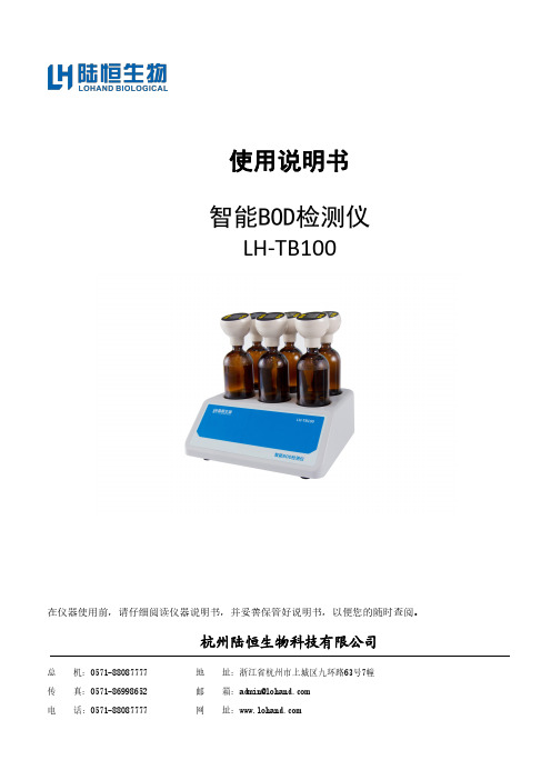
使用说明书智能BOD检测仪LH-TB100在仪器使用前,请仔细阅读仪器说明书,并妥善保管好说明书,以便您的随时查阅。
杭州陆恒生物科技有限公司总地址:浙江省杭州市上城区九环路63号7幢传邮箱:****************电网址:目录安全警示和注意事项 (1)免责及质保 (2)1、免责 (2)2、质保 (2)引言 (3)第一章第二章第三章技术参数及性能指标 (4)随箱物品介绍 (5)试验准备工作 (8)1、随箱物品清点: (8)2、实验物品准备:(用户自备) (8)第四章仪器介绍 (9)1、仪器工作原理 (9)2、按键功能 (9)3、仪器功能 (9)第五章BOD测试过程及特殊说明 (14)1、样品体积的选择 (14)2、测试过程 (15)3、特殊样品的预处 (17)第六章仪器校准与维护 (19)1、标准液的配制 (19)2、仪器准确性检验 (19)3、仪器的卫生 (19)4、测试端使用注意事项 (19)安全警示和注意事项◆在使用仪器之前,请仔细阅读“安全警示和注意事项”,以确保正确和安全的使用该仪器。
◆在遵守使用原则的前提下,可以增加产品的使用寿命,并可以避免发生危险。
◆以下为手册所提供的安全提示符:被禁止的操作需要注意的操作必须强制的操作禁止进行拆卸将插头从插座中拔出◆以下规定是安全警示和注意事项,是必须遵守的规定:●请勿在高湿、高温或灰尘多的地方存放或工作,以免造成仪器硬件故障。
●在实验过程中必须做好个人防护工作(实验服、手套、眼罩、口罩等)注意个人安全。
●仪器及备件不具备防水功能,应防止被水淋湿等情况发生。
●如果电源线已损坏(导线外露或断裂)请勿再使用,以免引起触电。
●请仔细阅读本手册,在掌握了仪器的各个功能及注意事项后再进行操作。
●避免强烈碰撞、震动,可能导致仪器损坏。
在搬运过程中建议使用仪器原包装。
●禁止仪器在腐蚀性气体的空间中工作,以免造成电路系统的损坏。
●请仔细阅读本手册,在掌握了仪器的各个功能及注意事项后,在进行操作。
百特智能数显表说明书工作状态下按SE T显示LOCY→按SET输入密码18→按SE T显示RAN9→按SE T通过△▽选择分度号→按SET显示Poin设置小数点→按SET显示r9.00设置量程下限→按SET显示r9.FS设置量程上限工作状态下按SET→通过△▽选择COrr按SET显示old.1→按SET通过△▽修正温度值参数设定说明:Locy:菜单上锁操作入口;按SET键确认;按△▽键退出;开锁密码为18Ran9.:分度号和量程设置入口;按SET键确认;按△▽键退出0-10/…/y:分度号设置;按△▽键设置;按SET确认PoIn:小数点位置设置;按△▽键设置;按SET确认R9.00:量程零点设置;按△▽键设置;按SET确认R9.FS:量程满度设置;按△▽键设置;按SET确认Corr:量程迁移和滤波时间设置菜单入口;按SET键确认;按△▽键取消Old.1:修正温度值;按△▽键设置;按SET确认按键说明:△:变更参数设定时,用于增加数值SET:参数设定确认键▽:变更参数设定时,用于减少数值常见故障处理:仪表通电不亮:供电电源未接入,正确接入仪表电源;接触不良,取出表芯确认弹片接触是否良好。
LED屏显示:broy分度号选择错,选择与输入信号相符的分度号;输入信号太大,调节与输入信号保证在仪表范围内;信号短线,正确接入信号线。
H.oFL.分度号选择错,选择与输入信号相符的分度号;输入信号太大,调节与输入信号保证在仪表范围内;仪表标定错误,选择正确标定信号重新标定。
L.Ofl.: 选择与输入信号相符的分度号;输入信号太小,调节与输入信号保证在仪表范围内;仪表标定错误,选择正确标定信号重新标定昌辉SWP系列智能仪表说明书控制方式:1、正确的接线仪表卡入表盘后,请参照仪表随机接线图接妥输入、输入及电源线,并请确认无误。
2、仪表的上电本仪表与电源开关,接入电源即进入工作状态。
3、仪表设备号及版本号的显示仪表在投入电源后,可立即确认仪表设备号及版本号。
丨中国;D旅游公路服务设施名称之辨文/周红萍尚琴琴陈建业JV搞要:在大众旅潑时代背下,公络与旅镲鲶融合虫现诸多探索。
在目前鲶实线中,旅 镲公路服务议施鲶名称呈现出不间子公路鲶命名方式.净弍从服务议施名称辨祈入孚,追溯 不同名称稔由束和演重,通过公路与旅潑公络鲶美系兮斩提出旅越公路服务设施名称应与公 路一致,洽服务站、侉卑点.观果台,驿站和营地雇作态服务议施的功铋极块。
一、引言随着大众旅游时代的到来,交通运输业作为支撑性、先导性 产业,与旅游的融合已是大势所 趋,而公路服务设施更是交旅融 合的主要平台和渠道。
在交通行业,将兼具游憩、生态、景观功能的公路称为旅游 公路;在文旅行业,称之为风景 道。
虽然旅游公路的定义尚未形 成定论,但有两点却达成共识:一是旅游公路技术等级不宜过 高,通常不包括高速公路,这是 由慢游的旅游交通特性决定的;二是旅游公路具有交通通行之外的游憩功能。
而服务设施是承载游憩功能的主要平台。
在对旅游公路服务设施的分类中,顾晓锋等m将服务设施分为服务中心、驿站、观景台、慢行驿站四种类型;冯全胜等121将旅游公路的游客设施按服务内容分为餐饮与住宿接待设施,公共服务设施以及汽车专用服务设施。
邱海莲®在研究美国风景道路侧游憩服务设施规划设计的硕士论文中,介绍风景道路侧游憩服务设施按照服务的主要功能可以分为五类设施,分别是道路引导类设施、交通连接类设施、解说服务类设施、户外游憩类设施以及旅游接待类设施。
其中户外游憩类设施包括观景台和野餐区,旅游接待设施包括服务区、住宿设施、餐饮设施。
杨星等w将服务设施按照高速公路和普通公路进行区分,高速公路旅游服务设施分为旅游主题服务区和旅游特色服务区两类,普通旅游公路服务设施分为旅游公路服务区、公路驿站、慢行驿站、观景区、港湾停车带、露营地六类。
可以看到,旅游公路服务92 |2021年第4期设施名称已吸收旅游、游憩相关 因素,呈现出与公路服务设施不 一致的名称。
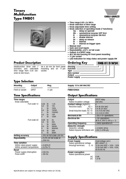
Product DescriptionMultifunction Multifunction timer with 7functions an d selectable time range from 0.05 sec-onds to 300 hours.48 x 48 mm for front panel mounting an d on 11-pin socket.•Time range 0.05 s to 300 h •Knob selection of time range •Knob adjustable time setting•Knob selection of operating mode (7 functions):Op -delay on operateRb -symmetrical recycler OFF first R -symmetrical recycler ON first Id -double interval Dr -delay on release In -intervalIo -interval on trigger open •Manual start•Gate and reset inputs•Repeatability: ±0.2% on full scale •Output: 8 A DPDT relay•48 x 48 mm housing for front panel mounting •11 pin socket•LED indication for relay status and power supply ONType SelectionMounting Output Plug Supply: 12 to 240 VAC/DC Front or socketDPDT11-pinFMB01DW24Time SpecificationsType FMB01TimersOutput SpecificationsFMB01Function and Time SettingLower left knob:Setting of functionOp-delay on operateRb-symmetrical recycler(OFF first)R-simmetrical recycler(On first)Id-double intervalDr-delay on releaseIn-intervalIo-interval on trigger open Lower right knob:Time unit selector0.1s(0.1 seconds)sec(seconds)10sec(10 seconds)min (minutes)10m (10 minutes)hrs(hours)10h(10 hours)Upper right knob:Time range selector12or 30Centre knob:Time setting on absolutescaleMode of OperationFunction OpDelay on operateThe time period begins as soon as the trigger contact is closed. At the end of the set elay time the relay operates and d oesn’t release until the power sup-ply is disconnected.The trigger contact is invalid while the timer is in opera-tion.Function RbSymmetrical recycler (OFF first)The time period begins as soon as the input contact is closed. The relay is OFF d uring the set d elay period, after this time it operates for the same time period. This sequence continues with equal OFF- and ON- time periods until power supply is interrupted.Function RSymmetrical recycler(ON first)The relay operates and thetime period begins as soonas the input contact isclosed. After the set d elayperiod the relay releases forthe same time period. Thissequence continues withequal ON- and OFF- timeperiods until power supply isinterrupted.Function IdDouble intervalThe relay operates and thetime period begins as soonas the trigger contact isclosed. The relay releases atthe end of this period orwhen the power supply isd isconnecte d. When thetrigger contact is openedthe relay operates again forthe set d elay period. If thetrigger contact is openedbefore the end of the firsttime period the second onebegins; if the trigger contactis closed before the end ofthe second time period therelay keeps ON and the firsttime period begins again.Function DrDelay on releaseThe relay operates as soonas the trigger contact isclose d. The time perio dbegins when the trigger con-tact is opened. The relayreleases at the end of theset d elay time or when thepower supply is disconnect-ed. The relay operates againwhen the input conctact isclosed again. If it is openedbefore the end of the d elaytime the relay keeps ON, anew time period begins assoon as the contact isclosed again.Function InIntevalThe relay operates and thetime period begins as soonas the trigger contact isclosed. The relay releases atthe end of this period orwhen the power supply isd isconnecte d. The relayoperates again when thetrigger contact is close dagain. If the trigger conctactis closed before the end ofthe d elay time, the d eviceresets and a new time peri-od starts.Function IoInteval on trigger openThe relay operates and thetime period begins as soonas the trigger contact isopened. The relay releasesat the end of this period orwhen the power supply isd isconnecte d. The relayoperates again when thetrigger contact is openedagain. If the trigger conctactis opened before the end ofthe d elay time, the d eviceresets and a new time peri-od starts.General SpecificationsFMB01Range and operation mode selectionOperating DiagramsFMB01Wiring DiagramsDimensionsOperating Diagrams (cont.)。
百特智能数显表说明书工作状态下按SE T显示LOCY→按SET输入密码18→按SE T显示RAN9→按SE T通过△▽选择分度号→按SET显示Poin设置小数点→按SET显示r9.00设置量程下限→按SET显示r9.FS设置量程上限工作状态下按SET→通过△▽选择COrr按SET显示old.1→按SET通过△▽修正温度值参数设定说明:Locy:菜单上锁操作入口;按SET键确认;按△▽键退出;开锁密码为18Ran9.:分度号和量程设置入口;按SET键确认;按△▽键退出0-10/…/y:分度号设置;按△▽键设置;按SET确认PoIn:小数点位置设置;按△▽键设置;按SET确认R9.00:量程零点设置;按△▽键设置;按SET确认R9.FS:量程满度设置;按△▽键设置;按SET确认Corr:量程迁移和滤波时间设置菜单入口;按SET键确认;按△▽键取消Old.1:修正温度值;按△▽键设置;按SET确认按键说明:△:变更参数设定时,用于增加数值SET:参数设定确认键▽:变更参数设定时,用于减少数值常见故障处理:仪表通电不亮:供电电源未接入,正确接入仪表电源;接触不良,取出表芯确认弹片接触是否良好。
LED屏显示:broy分度号选择错,选择与输入信号相符的分度号;输入信号太大,调节与输入信号保证在仪表范围内;信号短线,正确接入信号线。
H.oFL.分度号选择错,选择与输入信号相符的分度号;输入信号太大,调节与输入信号保证在仪表范围内;仪表标定错误,选择正确标定信号重新标定。
L.Ofl.: 选择与输入信号相符的分度号;输入信号太小,调节与输入信号保证在仪表范围内;仪表标定错误,选择正确标定信号重新标定昌辉SWP系列智能仪表说明书控制方式:1、正确的接线仪表卡入表盘后,请参照仪表随机接线图接妥输入、输入及电源线,并请确认无误。
2、仪表的上电本仪表与电源开关,接入电源即进入工作状态。
3、仪表设备号及版本号的显示仪表在投入电源后,可立即确认仪表设备号及版本号。
B型编程器使用说明书(使用前请仔细阅读)上海奥莉生电子有限公司2011-1-8目录1概述 (3)2使用说明 (3)2.1 编程器器件位置图 (3)2.2适用芯片型号及拨码开关选择 (4)2.3芯片放置 (4)2.3.1 烧录C61F183/ebike0x/iCooker01 (4)2.3.2 烧录C61F187 (5)2.3.3 烧录C61F121/133/23 (5)2.3.4 烧录C61F120/132/21 (5)2.4拨码开关功能分配 (5)3操作步骤 (6)1概述B 型编程器主要功能为从母片拷贝程序存储器、数据存储器、配置字到待编程片。
另外还可以对待编程片进行晶振校准(具体根据用户对拨码开关和跳线帽的设置)。
2使用说明2.1 编程器器件位置图39图1 编程器器件位置示意图1.+12V 电源插座2.电源开关3.电源指示灯(红色)4.状态指示灯(绿色)5.状态指示灯(红色)6.备用按键7.拨码开关8.跳线帽(晶振校准时才更改)9.母片插座10.待编程片插座11.ICSP编程接口2.2适用芯片型号及拨码开关选择编程器适用型号与拨码开关对应关系如表1所示。
注:1.拨码开关第1 位是FLASH空间加密选择位,ON:加密FLASH,OFF:不加密FLASH2.拨码开关第2 位是EEPROM空间加密选择位,ON:加密EEPROM,OFF:不加密EEPROM3.拨码开关第8位是芯片选择位,编程器上电前必须选择,否则会出错。
若被编程片为8 /14脚该位选择ON,若为28/32/40脚该位选择OFF。
2.3芯片放置母片放入母片插座,待编程片放入待编程片插座,母片与待编程片放入插座的位置一致。
2.3.1烧录C61F183/ebike0x/iCooker01母片为PIC16F883/8872.3.2 烧录C61F187母片为PIC16F8872.3.3 烧录C61F121/133/23母片为PIC16F630/676/6842.3.4 烧录C61F120/132/21母片为PIC12F629/675/6832.4拨码开关功能分配拨码开关如图2所示,下面的1代指拨码开关第1位,以此类推。

路博预设定机油枪使用说明书中文试用版警告: 在操作之前请仔细读和理解用法说明。
没有按照安全规章和其他基本安全预防措施操作可能导致严重人为事故。
使用说明预设定机油枪被设计用于机油的输送,当设定的油量到达时,喷嘴会自动关闭,停止机油输送。
技术参数流量范围 1 – 35 LPM (0.3-9.2 GPM)操作压力范围0.5 – 70 Bar (7-1000 PSI)操作温度Max. 60°C (140°F)精度±0.5%粘性8-5000 mPas5-Digital LCD Display (3/8"H xQuart, Pint, Gallon, Liter3/16"W) 数显单位接头1/2" BSP电源电压 1 Alkaline cell 9V操作数字表设备使用9V可更换的碱性电池,对于电池的更换请查看说明书D部分。
1、按键按数字直接设置AUTO按AUTO进入或退出自动模式RESET在手动或自动模式清除之前的设置OK/STOP按OK键确认动作或停止动作2、安装A. 安装前的准备工作1)系统压力的释放a) 关闭泵电源或截止阀b) 慢慢地打开枪的出油口处的油路截止阀,放出系统中的油到废油容器中,进行排油c)打开系统中所有的油路截止阀,启动油泵开始向系统供油d)让油泵处于打开状态,确保系统回路压力平衡2) 关闭截止阀3) 绕管装置根据场地,为了节约空间,用户需要配置下面设备,系统中的每个装置应进行有效的接地:a) 泵:依据生产厂家推荐的方法执行b)空气和流体软管:进行有效接地c)空气压缩机:依据生产厂家推荐的方法执行d) 油桶:使用当地允许型号的油桶警告不要在管连接处用特富龙胶带,可能导致接地效果失效B. 仪表连接软管在开始操作之前关闭油泵喷嘴与仪表连接3. 仪表的操作根据需要的功能选择不同的操作选项按AUTO键,液晶屏上会显示AUTO标示按OK/STOP键,为确定或停止按RESET键从菜单或已经进行的操作中退出,可以立即进行其他操作A. 显示模式仪表开始工作前按RESET键进行清零仪表显示即时当前计注值显示存储总值按RESET键可以上排计注值清零仪表将显示如下警告存储总值默认不可被改动,如果要更改,请联系服务中心权威扣下扳机进行加油放开扳机停止加油B. 操作模式B-1.手动模式按RESET进入手动模式仪表显示手动模式扣下扳机进行加油,当到所需的油量时,释放扳机,停止加油按RESET键清零B-2. 自动模式按AUTO仪表显示1-2-3-4-last :5组预存设定值可被频繁使用。

LB-CNP(B)便携式多参数快速测定仪使用说明书安装、使用本产品前,请详细阅读本使用说明书感谢您选用LB-CNP(B)便携式多参数快速测定仪。
在使用仪器前,请您仔细阅读本使用说明书,从中可以获得有关仪器性能、使用方法以及维护等方面的信息,这会有助于您更好的使用仪器。
如果您有好的建议或需要我们提供更进一步的服务,请按以下方式与我们联系:仪表一部400-6086-707仪表二部400-9929-113室内环保400-6316-707网址:厂址:山东青岛市城阳区金陵工业园锦宏西路与路博路交接口路博1号门。
目录目录 (2)安全警示和注意事项 (3)免责 (4)第1节引言 (5)第2节功能特点与技术参数 (6)第3节.试剂的配制 (8)第4节按键说明 (13)第5节仪器的基本操作 (14)5.1COD的测定 (14)5.1.1方法与原理: (14)5.1.2干扰及消除 (14)5.1.3水样氯离子的测定 (14)5.1.4水样的稀释 (14)5.1.5测定过程 (15)5.2总磷的测定 (19)5.2.1方法与原理: (19)5.2.2干扰和消除 (19)5.2.3水样的稀释 (20)5.2.3测定过程 (20)5.3氨氮的测定 (23)5.3.1方法原理 (23)5.3.2干扰及消除 (23)5.3.3水样的稀释 (23)5.3.4测定过程 (24)5.3.5水样的预处理 (26)5.4测量记录的保存与查询 (27)5.5设置系统时间 (28)5.6测量曲线的选择与修改 (29)第六节仪器校准及曲线的标定 (31)6.1标准溶液的配制: (31)6.2曲线值的校准: (31)第7节消解系统的操作 (34)7.1按键功能介绍 (34)7.2主工作界面及说明 (34)7.3消解器操作说明 (34)7.3.1设置温度参数: (34)7.3.2设置定时参数 (35)7.3.3启动/停止消解过程: (35)7.3.4设置PID参数 (35)第8节常见故障及排除方法 (36)安全警示和注意事项在使用仪器之前,请仔细阅读“安全警示和注意事项”,以确保正确和安全的使用该仪器。
LBT501单片机实验板使用手册●LBT501有主机板(Board)、电源(Power)和串行通信电缆(Line)三个部件。
●电源用市电交流220伏,主机板电源输入为隔离直流6伏电压,对人是安全的。
电源插座在主机板的背面。
●串行通信电缆一端接主机板的左上角DB9插座,另一端接PC计算机的串行口DB9(COM1或COM2)。
●从网站上可以获得单片机下载软件STC-ISP最新版本。
使用该软件即可将单片机程序的机器码HEX文档写入主板的STC89C516RD+单片机,然后即可让单片机执行你的程序。
●从网站上可以获得MCS51系列单片机的开发平台软件试用版Keil uVision。
支持MCS51的C语言和汇编语言设计、编译和调试。
●主机板由如下几个部分组成(详细原理图见网页):◆STC89C516RD+单片机(内部64KFLASH+1KRAM)◆电源稳压电路(输出VCC=5V)◆16发光二极管电路◆串行通信接口电路◆四位数码显示电路◆16键盘电路◆四个按钮电路◆蜂鸣器电路◆喇叭发音电路◆555周期性矩形波发生器●第一个实验是了解发光二极管的工作原理。
⏹做此实验不需要PC机,显然也不用通信电缆,使用工具取下主机板上的单片机。
⏹插入电源。
⏹拨动单片机(或单片机插座)左边上方的拨码开关,即可控制左边8支发光二极管的工作。
⏹拨动单片机(或单片机插座)左边下方的拨码开关,即可控制右边8支发光二极管的工作⏹实际上,每个发光二极管的正极(阳极)串入一个1000欧姆(1K)的电阻,电阻的另一端接到电源的正端(VCC),发光二极管的负极(阴极)串入一个开关,开关的另一端接到电源的负端(GND),当开关接通(ON)时,有电流(小于5mA)通过发光二极管,所以发光二极管亮;而开关断开(OFF)时,没有电流通过发光二极管,所以发光二极管不亮。
●第二个实验是了解数码管的工作原理。
⏹做此实验不需要PC机,显然也不用通信电缆,使用工具取下主机板上的单片机。

WORLD PROVIDER - INNOVATIVE HEATING SOLUTIONS411 Mason Street, Onalaska, WI 54650 • 800-345-7200 • 608-783-5691 • 608-783-6115 (fax) • Remote Fuel Hook-up Foreman 230/500 Oil500-131261Kit Contents:Tools required:- Adjustable wrench - 9/16 in. wrench - 3/4 in. wrench - Pipe wrench- Portable drill with 5/16 in. socket or 5/16 in. nut driverMaterials required:• Rags or towels• Appropriate PTFE thread sealant tape for use with fuel oil.• A ppropriate pipe fi ttings for connection to 3/8 in. inlet of fuel fi lter (used for drawing fuel from external fuel tank).Qualifications for installation of the kit:• You must be able to read and understand these instructions.• Y ou must be properly trained and have suf fi cient experience in servicing oil heaters and capable of testing the heater for proper operation.General information:The following instructions provide information on converting a two-pipe system to a one pipe system with the use of the remote fuel hook-up.Safety instructions:• To prevent leaks, always apply approved PTFE tape or piping compound to all connections.• Tighten all connections securely.DESCRIPTION QTY.Instructions, installation 1Remote fuel hook-up 1Bracket, mounting 1Screws, 5/16 in. hex head 4Cap, pipe, 3/8” NPT 1Hose, 3/8” x 15”2Nipple, 3/8” x 1-1/2”, black 1Elbow, 3/8” NPT, female, Galv.1Blue Cap 1Pipe Compound 1Hose Adapter3Reducing Bushing, 3/8” MNPT x 1/4” FNPT1FIG. 1C. Disconnecting Fuel Hoses1. D isconnect the return fuel hose at the elbow and from the pump. Save this hose to be used later.2. R emove the elbow from the tank and cap off the nipple with the 3/8” cap provided with the kit.4. R emove the bushing and the hose adapter from the inlet of the fuel fi lter.5. A ttach the previously removed hose adapter and bushing from step 4 to the hose’s swivel nut removed in step 3.HoseAdapter FittingsSwivel NutHose FittingDO NOT REMOVEBushingHose Adapter7. W rap the cord of the blue cap around the elbowand press fi t the cap onto the threads of the bush-ing. This will protect the threads from damage andallows the hose to be reconnected at a later dateif drawing fuel from the heater’s onboard tank isdesired.8. R emove the fuel hose between the outlet ofthe fuel fi lter and the pump. This hose may bediscarded. Removal of the fuel fi lter assembly fromthe bracket may aid in the hose removal.D. Installation1. I nstall the provided elbow and nipple to the outletof the fuel fi lter.Pump2. A ttach the remote hook-up bracket to the fuel fi lterbracket, as shown, using the mounting screwsprovided with kit.3. I nsert the remote hook-up onto the bracket.4. C onnect the hose with the male 3/8” NPT to theelbow of the fuel fi lter. If a 3/8” NPT hose is not oneof your hoses, install the 3/8” reducing bushing fromthe kit to the elbow than connect the 1/4” NPT hoseto the bushing. Connect its swivel nut to the bottomof the remote hook-up.5. C onnect the 1/4” NPT hose to fuel pump inlet portand the 3/8” swivel nut to the outlet port of theremote fuel hook-up.Fuel HoseFuel FilterBlueCapNippleElbowFuelFilterFuel FilterBracketRemoteHook-upBracketScrewsFuel PumpOutlet PortInlet2. Check all connections for tightness.BurnerFuel PumpReturn HoseRemote Fuel Hook-UpExternal Fuel TankFuel FilterSupply Hose to Remote Fuel Hook-UpSupply Hose to Fuel Pump。

Operating instructions BRTRF BRTRF consists of a BRTRF wireless room thermostat and a BR1 receiver. The BRTRF allows you to set the desiredroom temperature (setpoint). The unit features an ergonomic setting knob for ease of temperature control. DisplayRFCommissioning before start-upCommissioningRemove the black transit tabs from the alkaline batteries.Check to see if the battery holder is in the correct position.If no batteries are inserted, fit 2 alkaline batteries type AA in the battery compartment.Initial power-upOnce batteries are fitted, all symbols will appear onthe display as shown for about two seconds.Selecting the required temperatureTurn the setting knob counter clockwise todecrease the setpoint, or clockwise to increase thesetpoint in increments of 0.5 CThe required temperature is displayed next tothe comfort temperature symbolChanging the batteries1. Get two new batteries of type AA alkaline, 1.5 volts.2. Remove the battery holder, then the batteries, insert new batteries andreplace the battery holder.The old, set temperature must be checked!3. Make certain the old batteries are disposed of properly, incompliance with environmental requirements.Energy saving tips without sacrificing comfortNever allow room temperatures to exceed 21 C.NOTE:You can press the OVERRIDE button on the receiver to manually switch ON/OFF for a faulty room unit or transmission signal.Front View ReceiverConfiguration instructions for the BOSS BRTRFThe Transmitter BRTRF room unit and the receiver BR1 are set to communicate (bonded) with each other at the factory. If they fail to do so at installation or it is necessary to re bond the units due to loss of communication please follow the following instructions.1. If room unit is wall mounted remove from wall or if on table stand remove grey backing plate2. For receiver Reset by simultaneously pressing the LEARN & OVERRIDE button for 4 seconds.3. On Receiver Press and release the LEARN button. This puts the receiver in learn mode.4. On room unit Press and release the LEARN button on the back. Green LED will flash on receiver and come on solid after 20seconds5. A green solid LED indicates a good signal, a red solid LED indicates no signal.6. To test transmission, press the TEST button on the transmitter, this switches the relay to ON on the receiver regardless of temperature. The RF TEST symbol appears on the display (1 s).7. An orange LED indicates that the relay is on.。
JBB1型数字式标准干湿表使用说明书JBB1型数字式标准干湿表温度采用铂电阻测温法,湿度采用干湿球测湿法,设计采用自校准技术,提高了温度稳定性和时间稳定性,技术指标达到了国家二级计量标准要求,适用于较高精度的温度及湿度测试。
一、技术指标1.温度通道温度测量范围:-50℃~100℃,最大允许误差:±0.06℃。
2.湿度通道温度测量范围:0℃~40℃,最大允许误差:±0.06℃。
湿度测量范围:10% RH~100%RH,最大允许误差:±2%RH。
3.配备RS232接口,可接入湿度检定箱进行湿度控制。
4.通风速度:不小于3m/s。
二、使用环境1.环境温度:10℃~40℃;2.电源:220V AC,良好接地,无强电磁场干扰。
3.现场使用须注意防尘、防潮。
二、面板、通讯线及传感器接线说明!本仪器使用前请检查电源是否符合要求,以保证人员和设备安全。
开机前请连接好传感器,禁止开机状态下热插拔。
后面板示意图:通风干湿表湿度传感器接线说明接线编号传感器1 干球传感器电流正端2 干球传感器电流负端3干球传感器屏蔽线4 湿球传感器电流正端5湿球传感器电流负端6湿球传感器屏蔽线9干球传感器电压正端10干球传感器电压负端12湿球传感器电压正端13湿球传感器电压负端温度传感器接线说明:接线编号传感器1 温度传感器电流正端2温度传感器电流负端3 温度传感器屏蔽线4温度传感器电压正端5 温度传感器电压负端RS232接口与湿度检定箱连接通讯线接线说明:9芯插头(孔)(标准器) 9芯插头(针)(湿度检定箱)5 73 22 3前面板示意图显示窗显示内容为:干球温度,湿球温度,相对湿度,空气温度。
三、操作说明连接好电源和传感器后,按下电源开关,本机即开始工作。
开机后,即进入工作菜单。
此时,显示屏第一行显示通风干湿表干球温度值,第二行显示通风干湿表湿球温度值,第三行显示相对湿度值,第四行显示空气温度值。
在此状态下,只有“确定”键起作用。
![T+地磅管理模块说明-NEW[5篇范文]](https://img.taocdn.com/s1/m/be8509aba1116c175f0e7cd184254b35eefd1ad4.png)
T+地磅管理模块说明-NEW[5篇范文]第一篇:T+地磅管理模块说明-NEWT+电子秤磅秤管理模块说明日期:2015-04-15模块介绍1.1开发背景目前开发地磅软件的公司有很多,但能和畅捷通T+软件结合的很少,即使有和T+对接的地磅软件,但因其软件系统的各自独立性,在系统登录,货品管理上都很难达到统一,用户要操作不同的系统,会严重影响效率和操作的方便性,我们为了解决该问题,在畅捷通T+的系统上做了扩展,真正达到了零整合,使用畅捷通T+的用户再也不用频繁的登录各系统,可以方便快捷的管理地磅称重工作。
1.2系统简介畅捷通T+电子秤磅秤系统广泛应用于以物料为主的生产、加工、销售型企业,如:钢铁、冶金、铸造、化工生产、矿业、焦化、建材、电厂、粮食加工等企业。
T+电子秤磅秤系统利用先进计算机技术和严密的流程设计可以帮助企业从根本上解决计量、结算过程中的舞弊行为,有效的避免因此造成的经济损失。
T+电子秤磅秤系统可以直接与畅捷通T+系统中的库存系统挂接,可以自动生成进货销货单和出入库单据,从而有效杜绝各部门人为作弊行为,并可大大减轻司磅人员、仓库人员、财务人员的工作量,提高工作效率。
1.3企业常见问题λ司磅员在计量数量上作弊;λ场内换车现象;λ车辆不完全上磅,或两车同时上磅,造成计量数据不准确;λ材料结算员在材料结算中作弊;λ销售发货中出现超提单发货;λ不过磅而直接出场。
1.4功能介绍图1.1 称重管理主界面图1.2 地磅管理相关菜单图1.3 称重记录管理1.4.1地磅参数按地磅说明书中的参数值填写,点击“测试”,窗口左下方显示采集数据信息,若数据不正确,按“终止”按钮,重新设置参数继续测试,直到采集到正确的数据,点击“保存”按钮。
可同时设置多组不同的地磅参数,并按自己的规则命名,已使系统同时支持多组地磅。
如下图所示:图1.2.1 地磅参数设置界面1.4.2 车辆管理如下图所示:图1.4.2 车辆管理界面1.4.3 存货管理、仓库管理、收/发货客户信息管理同T+,可在T+相关界面设置。
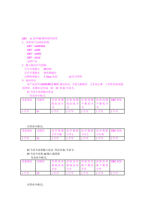
LBT ---A系列IO模块使用说明1、该系列产品涵盖范围:LBT—A6DI4DOLBT—A8DILBT—A8DOLBT—A8AI定制产品2、输入输出信号规格:①开关量输入DC24V②开关量输出继电器输出③模拟量输入4-20ma电流10位分辨率3、通讯协议本产品采用MODUBUS-RTU通讯协议,方便与触摸屏文本显示器工控机等组成通讯网络。
本模块支持01 02 03 和05号命令。
01号命令读取输出状态发送命令格式:设备地址功能码读取线圈地址高字节读取线圈地址低字节读取线圈个数高字节读取线圈个数低字节CRC校验1字节01 1字节1字节1字节1字节2字节应答命令格式:设备地址功能码返回数据字节个数返回数据字节1返回数据字节2返回数据字节NCRC校验1字节01 1字节1字节1字节1字节2字节02号命令读取输入状态用法同01号命令。
03号命令读取AI输入通道值发送命令格式;设备地址功能码读取寄存器地址高字节读取寄存器地址低字节读取寄存器个数高字节读取寄存器个数低字节CRC校验1字节03 1字节1字节1字节1字节2字节应答命令格式:设备地址功能码返回数据字节个数节返回第一个寄存器数据高字节返回第一个寄存器数据低字节返回第N个寄存器数据高字节返回第N个寄存器数据低字节CRC校验1字节03 1字节1字节1字节1字节2字节05号命令写单线圈状态发送命令格式:设备地址功能码写入线圈地址高字节写入线圈地址低字节写入值高字节写入值低字节CRC校验1字节05 1字节1字节1字节1字节2字节应答命令格式:设备地址功能码写入线圈地址高字节写入线圈地址低字节已写入值高字节已写入值低字节CRC校验1字节05 1字节1字节1字节1字节2字节。
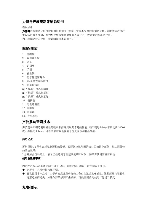
力博得声波震动牙刷说明书谨以致谢力博得声波震动牙刷保护你的口腔健康,有助于牙齿不受腐蚀和刺激牙龈,并能清洁舌部产生异味的有害细菌,是为想使牙齿保持健康的人设计的一种新型声波震动牙刷。
为了您能更好的使用,请详细阅读本说明书。
配置(图示)1.便携座2.备用刷头位3.刷头4.识别环5.手柄6.输出轴7.防水橡皮密封件8.开/关模式选择按扭9.充电指示灯(a)“标准”模式指示灯(b)“舒适”模式指示灯(c)“护理”模式指示灯10. 便携盒11. 充电透明盖12. 电源线13. 充电器14. 充电部位声波震动牙刷技术声波震动牙刷是利用磁性的吸引和排斥实现其卓越的性能,该牙刷每分钟水平震动约31000次,振幅约1.1mm,可以柔和有效地预防牙齿受腐蚀和刺激牙龈。
其它优点牙刷每隔30秒你会感觉到短暂的停顿,提醒您应该均衡清洁口腔的四个部位,以达到最佳的清洁效果;2分钟后会自动停止,表示已经达到牙医建议的刷牙时间。
如果再使用需重新启动。
使用前注意事项因这种声波高速震动牙刷不同于传统的电动牙刷,所以,请注意以下事项:●刷牙时,只需轻轻按压牙刷;●首次使用本产品时,由于声波高速震动有些人会有刺激或发麻感觉。
这种感觉将随着你逐渐适应而消失。
如果你开始感到牙齿发麻,可能需要首先使用“舒适”模式。
充电(图示)●请将牙刷手柄放在充电座上,并将充电座插入电源插座,绿色充电指示灯亮起,充电开始。
电池充满电量后,红色指示灯亮起,表示可以正常使用了;●充满电量后,牙刷将可使用约180分钟;●下列情况,务必对牙刷充电28小时:⑴首次使用之前;⑵六个月以上没有使用;●你至少一年将其彻底放电一次,放电时拔下充电插座,并通过正常使用使电池电量耗尽。
注意(图示)●在充电时,牙刷主体电池位置会发热,但这是正常的;●只能使用附送的专用充电器;●如果充足电后,牙刷只能使用很短的时间,这表示电池已经达到使用寿命,请将本产品拿到授权的维修中心去换电池。