ITR9608中文资料
- 格式:pdf
- 大小:363.17 KB
- 文档页数:6
ADI 中文版数据手册是英文版数据手册的译文,敬请谅解翻译中可能存在的语言组织或翻译错误,ADI 不对翻译中存在的差异或由此产生的错误负责。
如需确认任何词语的准确性,请参考ADI 提供的最新英文版数据手册。
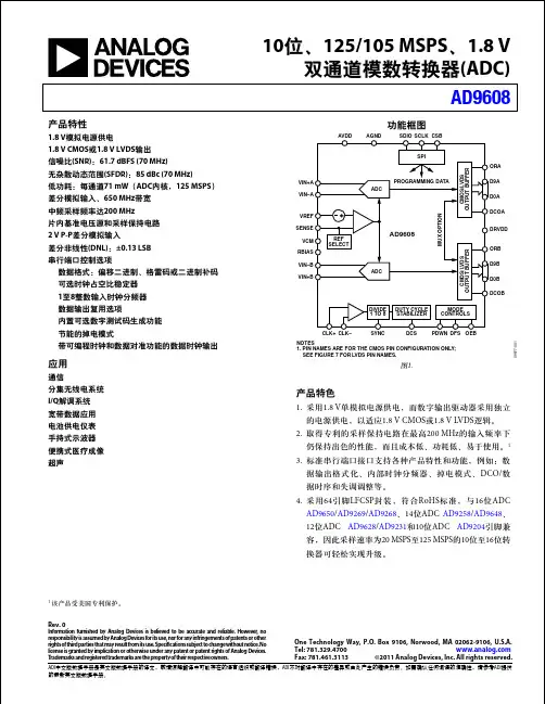
10位、125/105 MSPS 、1.8 V双通道模数转换器(ADC)AD9608Rev. 0Information furnished by Analog Devices is believed to be accurate and reliable. However , no responsibility is assumed by Analog Devices for its use, nor for any infringements of patents or other rights of third parties that may result from its use. Speci cations subject to change without notice. No license is granted by implication or otherwise under any patent or patent rights of Analog Devices. T rademarks and registered trademarks are the property of their respective owners.One Technology Way, P.O. Box 9106, Norwood, MA 02062-9106, U.S.A.Tel: 781.329.4700 Fax: 781.461.3113 ©2011 Analog Devices, Inc. All rights reserved.功能框图VIN+A VIN–AVREF SENSE VCM RBIAS VIN–BVIN+BORA D0A D9A DCOA DRVDDORB D9B D0B DCOBSDIO AGNDAVDDSCLK SPIPROGRAMMING DATAM U X O P T I O NPDWN DFS CLK+CLK–MODE CONTROLSDCS DUTY CYCLE STABILIZER SYNC DIVIDE 1TO 8OEBCSBREF SELECTADCC M O S /L VD S O U T P U T B U F FE RADCC M O S /L VD S O U T P U T B U F FE RAD9608NOTES1. PIN NAMES ARE FOR THE CMOS PIN CONFIGURATION ONLY; SEE FIGURE 7 FOR LVDS PIN NAMES.09977-001图1.1 该产品受美国专利保护。
DELLTMOVERVIEWMARKETING SYSTEM CON FIGURATIONSDETAILED ENGINEERING SPECIFICATIONSTABLE OF CONTENTSDELL OPTIPLEX 960Professional users seeking a sophisticated, powerful desktop need to look no further than the OptiPlex 960. The stylish new OptiPlex 960 delivers advanced technologies to tackle any challenge without missing a beat. Available with top-of-the-line processors, generous memory options, native support for dual high-resolution displays, and a diskless option to support flexible computing environments are just a sampling of the built-in productivity options available. Protect systems and data with your choice of leading-edge hardware and software security options. Rest easy knowing IT professionals will have the system management tools they need, with the global Dell service and support options to cover systems from acquisition to asset retirement. Performance at the OptiPlex 960 level is just one of the reasons Dell is a world leader in business desktops—and why OptiPlex is the easiest choice you’ll make today.OPTIPLEX MEANS BUSINESSThe OptiPlex 960 delivers serious performance in a scalable platform you can build a business on:Long-range planning support with up to a 24-month lifecycle, stable images, and managed transitionsHorsepower for your users' demanding applications with options including the Intel®Core™2 Quad ProcessorAdvanced manageability tools for IT, including next generation Intel®vPro™ technologySmaller redesigned chassis including a space saving all-in-one optionOPTIPLEX SECURITYFrom hardware to software, from local to remote, The OptiPlex 960 gives you the power to choose your level of security:Isolate system threats and protect your network infrastructure with Intel® vPro™ client isolation featuresProtect sensitive data with optional full disk encryption hard drivesBuilt-in TPM helps protect the network from unauthorized access, while enabling multi-factor authentication via optional Smart Card Reader and/or fingerprint reader (note, TPM may not be available in all countries)OPTIPLEX IS EASY TO OWNProductivity meets manageability in the OptiPlex 960, with a suite of highly customizable, global service and support options throughout the PC lifecycle. For users and IT professionals alike, the OptiPlex 960 is easy to own, enabling:Remote system diagnosis and repair, reducing desk-side visits with Intel®vPro™ technologyFaster repairs for users with Intel®vPro™ Fast Call for Help Technology enabling end-user initiated remote supportEase of deployment with the OptiPlex 960’s support for integrated wireless networkingTime-saving tool-less cover removal for access to tool-less internal componentsOPTIPLEX GETS GREENDell is committed to being the greenest PC company on the planet. And the OptiPlex 960 delivers:Help reduce power consumption—and cost—with Dell’s power supply, which is up to 88% efficientEnjoy a quieter workplace with Dell’s ultra-silent QuietKit noise-reduction solutionReduced environmental impact with systems built with 10% post-consumer recycled content (Available for units built after December, 2008)Minimize power usage with Dell EnergySmart power management technologyEnvironmental sensitivity with the OptiPlex 960’s Energy Star, EPEAT-Gold, TCO, and Blue Angel certificationMINI TOWER COM PUTER (MT) VIEWMINI TOWER COM PUTER (MT) VIEW (CONT.)DESKTOP COM PUTER (DT) VIEWDESKTOP COM PUTER (DT) VIEW (CONT.)SMALL FORM FACTOR CO MPUTER (SFF) VIEWSMALL FORM FACTOR CO MPUTER (SFF) VIEW (CONT.)MARKETING SYSTEM CONFIGURATIONSNO TE:Of feri ng s m a y v ar y b y regi on.Fo r m ore i nf orm ati on r ega rdi ng t he c onfi gura ti on o f yo ur com puter,cl i ck S tar t>H el p and S uppor t a nd sel ec t th e opti on to vi ew i nform ati on abou t you r com pute r.OPERATING SYSTEMNO TE:One of t he fol l ow i ng Opera ti ng S ys tem s w i l l be prei ns tal l ed.CHIPSETPROCESSORNO TE:Gl obal S t andard P roduct s (GS P) ar e a s ubset of Del l's rel ati on s hi p produc ts tha t a re m anaged for avai l abi l i t y and s yn chro n i z ed transi ti ons on a w orl dw i de basi s.The y ensu r e the s am e pl at form i s avai l abl e f or purcha se gl obal l y.Thi s al l ow s custom er s to r ed uce th e num ber of c onfi gurati on s m anage d on a w orl dw i de basi s,t her eb y r educi ng t hei r cos ts.Th e y al so en a bl e com pani e s to i m pl em ent gl obal I T s tan dard s b y l o cki ng i n speci fi c prod uct con fi gu rati on s w orl dw i de.The fol l ow i ng GS P proces s ors i den ti fi ed bel ow w i ll be m ade avai l abl e to D el l cus tom e rs.NO TE:P roces sor num ber s are no t a m ea sur e of pe rform an ce.ADVANCED SYSTEM MANA GEABILITY M ODESNO TE:Hardw ar e m anag e m ent m ode op ti ons al l ow you to sel ec t th e ri gh t s ys t em s m anag em en t f ea t ure supp ort for you r en terp ri se.Del l’s i nnova ti ve appro ach to scal abl e r em ote cl i ent m anagem en t of fer s you a choi c e of bui l t-i n hardw ar e m anag e m ent cap abi l i ti e s ac ross pl atfo rm off eri ngs.Th e l ate st g ener ati on o f I ntel®vP ro™ t echnol og y pr ovi de s the capabi l i t y t o m anage yo ur i ns ta l l base of s ys tem s r ega rdl es s of th e pow er sta te o r hardw ar e func ti onal i t y of the s ys tem.Thi s func ti onal i t y al l ow s I T to addre ss m an y i ssu e s rem ot el y ra the r th an ha vi ng to ph ys i cal l y vi si t s ys t em s.Th e Opti P l e x 960 suppor t s the l a te st g ener ati on o f I ntel®vP ro™ tec hnol og y.I ntel® i AM T te chnol og y/I ntel®vP r o™ te chnol og y s upport t he fol l ow i ng fe at ures:As s et repo rti ng and i n ve ntor y ca pabi l i ti e s,R em ot e t roubl esho oti ng and r e pai r,Cl i en t S ys t em I sol a t i on,Rem ot e patchi ng/upd ati ngI ntel® vP ro™ te chnol og y adds th es e addi ti on al fe a ture s:Cl i ent i ni ti al ed “Fa st C al l for Hel p”/be yo nd fi rew al l s ys tem s m an agem en t capabi l i t y,M i crosof t N AP support, Hard ened s ecu ri t y m oni to ri ng,S upport fo r the l at e st gen era ti on of I n tel® C ore™ 2 Qu ad P roce sso rs*The f u nc t ion alit y des c ri be d ab ov e re qui res a n ap pr o pri at e s of t wa re m ana gem ent c ons ol e* This functionality requires the appropriate software management consoleMEM ORYYour com put er suppo rt s a m axi m um of 8GB of m em or y w hen you use f our 2GB DI M M s; how eve r,32-bi t opera ti ng s ys t em s,such as th e 32-bi t v ersi on o f M i crosoft®W i ndow s®X P, can onl y u se a m axi m um of 4GB of addre ss spa ce.M oreove r,cer tai n com ponent s w i t hi n the com pute r r equi re addre ss spa ce i n the 4G B rang e. An y add re ss sp ac e re se rved for thes e com pon e nts c anno t be us ed b y com puter m em or y;the re fore,the am ount of m em or y av ai l a bl e to th e oper ati ng s ys t em i s l ess than 4GB.NO TE:The enti r e 8G B m e m or y range i s av ai l abl e t o 64-bi t oper ati ng s ys tem s.M em or y m odul e s shoul d be i nstal l ed i n pai rs of m atch ed m em or y si z e,spe ed,and technol og y.I f th e m em or y m odul es ar e no t i ns tal l ed i n m atch ed pai rs,t he co m puter w i l l conti nu e to o pera te,bu t w i th a sl i ght r educti on i n perform an ce.MEM ORY (CONT.)1 The total amount of available memory will be less than 4GB. The amount less depends on the actual system configuration. To fully utilize 4GB or more of memory requires a 64-bit enabled processor and 64-bit operating system.DRIVES AND REM OVABLE STORAGEDRIVES AND REM OVABLE STORAGE (CONT.)1 For hard drives, GB means 1 billion bytes and TB equals 1 trillion bytes; actual capacity varies with preloaded material and operating environmentand will be less.2 Discs burned with this drive may not be compatible with some existing drives and players; using DVD+R media provides maximum compatibility.3 DVD-ROM drives may have write-capable hardware that has been disabled via firmware modifications.SYSTEM BOARD CONNECT ORSNO TE : S ee De tai l ed E ngi neeri ng S pe ci fi c ati on s fo r m axi m um card di m ensi o ns suppor t.GRAPHICS/VIDEO CONTR OLLERNO TE : M T suppor ts ful l h ei ght card, D T suppor ts l ow profi l e c ard or ful l h e i ght c ard w i th op ti onalri ser. S FF support s l ow profi l e ca rd.EXTERNAL PORTS/CONNE CTORSNO TE : MT suppor ts ful l h ei ght card, D T suppor ts l ow profi l e c ard or ful l h e i ght c ard w i th op ti onal ri ser. S FF support s l ow profi l e ca rd.1Up to 1.7 GB of system memory may be allocated to support integrated graphics, depending on operating system, system memory size and other factors.EXTERNAL PORTS/CONNE CTORS (CONT.)COMM UNICATIONS - NETWORK ADAPTER (NIC)NO TE:M T support s ful l h ei ght c ard,D T s uppor ts l ow profi l e card or ful l hei ght ca rd w i th opti onal ri s er.1 This term does not connote an actual operating speed of 1 Gb/sec. For high speed transmission, connection to a Gigabit Ethernet server and network infrastructure is required.2 Intel Active Management Technology supported only with integrated Intel Gigabit Ethernet LANCOMM UNICATIONS – MODEMNO TE:M T support s ful l h ei ght c ard,D T s uppor ts l ow profi l e card or ful l hei ght ca rd w i th opti onal ri s er.COMM UNICATIONS – WIRELESSAUDIO AND SPEAKERSKEYBOARD AND MOUSE SECURITY SERVICE AND SUPPORTNO TE : For m ore det ai l s o n Del l S ervi ce P l ans pl ea se to go to: ww w.del /servi c e/se rvi c e_pl a nsSOFTWARE1For a copy of our guarantees or limited warranties, please write Dell USA L.P., Attn: Warranties, One Dell Way, Round Rock, TX 78682. For more information, visit /warranty. 2Service may be provided by third-party. Technician will be dispatched if necessary following phone-based troubleshooting. Subject to parts availability, geographical restrictions and terms of service contract. Service timing dependent upon time of day call placed to Dell. U.S. only.1TPM may not be available in certain countriesDETAILED ENGINEERING SPECIFICATIONSSYSTEM DIM ENSIONS (P HYSICAL)NO TE:S ys tem W ei ght* and S hi ppi ng W ei ght* i s based on a t ypi c al confi g urati on and m a y va r y b a sed on P C confi gur ati on. A t yp i c al confi gur ati on i ncl ud es:i ntegr at ed graphi cs,one hard dri v e,one opti cal d ri ve,and one di sk et te dri ve.SYSTEM BOARD CONNECT OR M AXIM UM ALLOWABLE DIMENSIONS* Card length can be longer than standard Half-Length Card but cannot be a Full-Length Card.** 6.9/17.53 in/cm is longer than the standard Half-Length CardSYSTEM LEVEL ENVIRON M ENTAL AND OPERATING CONDITIONSPOWERPOWER (CONT.)AUDIOCOMM UNICATIONS - LANNO TE:M T suppor ts ful l h ei ght card,D T suppor ts l ow profi l e c ard or ful l h e i ght c ard w i th op ti onal ri ser.S FF support s l ow profi l e ca rd.1 This term does not connote an actual operating speed of 1 Gb/sec. For high speed transmission, connection to a Gigabit Ethernet server and network infrastructure is required.COMM UNICATIONS - INTEGRATED LAN (CONT.)COMM UNICATIONS – MODEMNO TE:M T suppor ts ful l h ei ght card,D T suppor ts l ow profi l e c ard or ful l h e i ght c ard w i th op ti onal ri ser.S FF support s l ow profi l e ca rd.COMM UNICATIONS – MODEMCOMM UNICATIONS – WIRELESSGRAPHICS/VIDEO CONTR OLLERNO TE:M T suppor ts ful l h ei ght card,D T suppor ts l ow profi l e c ard or ful l h e i ght c ard w i th op ti onal ri ser.S FF support s l ow profi l e ca rd.Up to 1.7 GB of system memory may be allocated to support integrated graphics, depending on operating system, system memory size and other factors.Note: DVI and VGA can be used concurrently for multi-monitor display in DOS. The Display Port controller does not support multi-monitor display in DOS, but it does in the OS after the driver is loaded.1DMS-59 to VGA or DMS-59 to DVI adaptors required.HARD DRIVESNote: For hard drives, GB means 1 billion bytes and TB equals 1 trillion bytes; actual capacity varies with preloaded material and operating environment and will be less.OPTICAL DRIVES1 Discs burned with this drive may not be compatible with some existing drives and players; using DVD+R media provides maximum compatibility.OPTICAL DRIVES (CONT.)More details for optical drives can be found at: /support/systemsinfo/documentation.aspx?c=us&l=en&s=gen&~cat=7CHASSIS ENCLOSURE & VENTILATION REQUIREM ENTSENCLOSURE VENTILATIONIf your enclosure has doors, they need to be of a type that allows at least 30% airflow through theenclosure (front and back).ENCLOSURE MINIMUM CLEARANCELeave a 10.2 cm (4 in.) minimum clearance on all vented sides of the computer to permit the airflowrequired for proper ventilation.RECOMMENDED ENCLOSUREDo not install your computer in an enclosure that does not allow airflow. This restricts the airflow andimpacts your computer’s performance, possibly causing it to overheat.OPEN DESK MINIMUM CLEARANCEIf your computer is installed in a corner, on a desk, or under a desk, leave at least 5.1 cm (2 in.) clearancefrom the back of the computer to the wall to permit the airflow required for proper ventilation.REGULATORY COMPLIANCE AND ENVIRONMENTALProduct related conformity assessment and regulatory authorizations including Product Safety, Electromagnetic Compatibility (EMC), Ergonomics, and Communication Devices relevant to this product may be viewed at /regulatory_compliance. The Regulatory Datasheet for this product is located at /regulatory_compliance.Details of Dell's environmental stewardship program to conserve product energy consumption, reduce or eliminate materials for disposal, prolong product life span and provide effective and convenient equipment recovery solutions may be viewed at/environment. Product related conformity assessment, regulatory authorizations, and information encompassing Environmental, Energy Consumption, Noise Emissions, Product Materials Information, Packaging, Batteries, and Recycling relevant to this product may be viewed by clicking the Design for Environment link on the webpage.ACOUSTIC NOISE EMISSION INFORMATIONOPTIPLEX 960 MTThe Declared Noise Emission in accordance with ISO 9296 for the Dell Optiplex 755 MT is as follows: (all values L WAd expressed in bels; 1 bel=10 decibels, re 10-12Watts)OPTIPLEX 960 DTThe Declared Noise Emission in accordance with ISO 9296 for the Dell Optiplex 755 DT is as follows: (all values L WAd expressed in bels; 1 bel=10 decibels, re 10-12Watts)OPTIPLEX 960 SFFWAd expressed in bels; 1 bel=10 decibels, re 10-12 Watts)All tests are conducted according to ISO 7779 and declared according to ISO 9296 except 90% CPU. For this mode, the system CPU was stressed at 90% utilization with no other peripheral device spinning. This test mode is not specified in ISO 7779, but was measured using the same microphone distances and measurement techniques defined for the other reported operating modes. Declared Sound Power rounded to nearest tenth of a bel per ISO 9296 section 4.4.2。

Continuous DrainParameter T =25°C Gate-Source Voltage Drain-Source Voltage Absolute Maximum Ratings T =25°C unless otherwise notedAOT10N60 / AOTF10N60DSDSSymbolMin Typ Max Units600V 700V BV DSS /∆T J 0.65V/ oC 110I GSS ±100nA V GS(th)345V R DS(ON)0.60.75Ωg FS 15S V SD 0.731V I S 10A I SM36A C iss 110013201600pF C oss 105130160pF C rss 7.59.311pF R g33.86ΩQ g 31.140nC Q gs 6.410nC Q gd 14.420nC t D(on)2835ns t r 6680ns t D(off)7695ns t f 6480ns t rr 290350ns Q rr3.94.7µC4.4THIS PRODUCT HAS BEEN DESIGNED AND QUALIFIED FOR THE CONSUMER MARKET. APPLICATIONS OR USES AS CRITICAL COMPONENTS IN LIFE SUPPORT DEVICES OR SYSTEMS ARE NOT AUTHORIZED. AOS DOES NOT ASSUME ANY LIABILITY ARISING OUT OF SUCH APPLICATIONS OR USES OF ITS PRODUCTS. AOS RESERVES THE RIGHT TO IMPROVE PRODUCT DESIGN,FUNCTIONS AND RELIABILITY WITHOUT NOTICE.V DS =480V, T J =125°C Breakdown Voltage Temperature CoefficientI D =250µA, V GS =0V Gate Threshold VoltageV DS =V GS , I D =250µA V DS =600V, V GS =0V V DS =0V, V GS =±30V Zero Gate Voltage Drain Current Gate-Body leakage current Body Diode Reverse Recovery TimeI D =250µA, V GS =0V, T J =25°C V GS =10V, I D =5A Reverse Transfer Capacitance I F =10A,dI/dt=100A/µs,V DS =100VV GS =0V, V DS =25V, f=1MHz SWITCHING PARAMETERS I DSS µA Maximum Body-Diode Pulsed CurrentElectrical Characteristics (T J =25°C unless otherwise noted)STATIC PARAMETERS Parameter Conditions Static Drain-Source On-Resistance Forward TransconductanceDiode Forward Voltage I S =1A, V GS =0V V DS =40V, I D =5ATurn-On Rise Time Turn-Off DelayTime V GS =10V, V DS =300V, I D =10A, R G =25ΩGate resistanceV GS =0V, V DS =0V, f=1MHzTurn-Off Fall TimeTotal Gate Charge V GS =10V, V DS =480V, I D =10AGate Source Charge Gate Drain Charge BV DSS Drain-Source Breakdown Voltage I D =250µA, V GS =0V, T J =150°C Body Diode Reverse Recovery Charge I F =10A,dI/dt=100A/µs,V DS =100VMaximum Body-Diode Continuous Current Input Capacitance Output Capacitance Turn-On DelayTime DYNAMIC PARAMETERS A: The value of R θJA is measured with the device in a still air environment with T A =25°C.B. The power dissipation P D is based on T J(MAX)=150°C, using junction-to-case thermal resistance, and is more useful in setting the upper dissipation limit for cases where additional heatsinking is used.C: Repetitive rating, pulse width limited by junction temperature T J(MAX)=150°C.D. The R θJA is the sum of the thermal impedence from junction to case R θJC and case to ambient.E. The static characteristics in Figures 1 to 6 are obtained using <300 µs pulses, duty cycle 0.5% max.F. These curves are based on the junction-to-case thermal impedence which is measured with the device mounted to a large heatsink, assuming a maximum junction temperature of T J(MAX)=150°C.G. L=60mH, I AS =4.4A, V DD =50V, R G =25Ω, Starting T J =25°CRev 0. July 2008VdsC ha rgeG ate Charge Test Circuit & W av eformResistiv e Switching Test Circuit & W av eformsVddVdsI dVgsB V I Unclamped Inductive Switching (UIS) Test Circuit & W av eformsARDSS2E = 1/2 LI VddARAR。
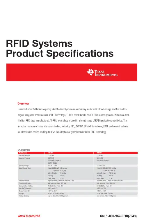
RFID SystemsProduct Specifi cationsOverviewTexas Instruments Radio Frequency Identifi cation Systems is an industry leader in RFID technology, and the world’slargest integrated manufacturer of TI-RFid™ tags, TI-RFid smart labels, and TI-RFid reader systems. With more than1 billion RFID tags manufactured, TI-RFid technology is used in a broad range of RFID applications worldwide. TI isan active member of many standards bodies, including ISO, ISO/IEC, ECMA International, ETSI, and several nationalstandardization bodies working to drive the adoption of global standards for RFID technology. Array/rfi d Call 1-800-962-RFID(7343)* Dependent on the confi guration used, the RF regulation in country of use and the environmental conditionRFIDTag-it™ HF-I Standard Transponder Inlays/rfi dCall 1-800-962-RFID(7343)SPAT178A© 2010 Texas Instruments Incorporated Printed in U.S.A.Printed on recycled paperRFID010208AEurope, Middle East and Africa (EMEA)European Toll Free* 00800 275 83927International +49 (0) 8161 80 2121Russian Support +7 (495) 981 07 01*The European Toll Free number is not active in all countries. If you havetechnical difficulty calling the toll-free number please use the international numberFax: +49 (0) 8161 80 2045Business Hours (Central European Time)Monday – Wednesday 10:00 – 18:00Tuesday – Thursday 09:00 – 18:00Friday 09:00 – 16:00E-mail:******************Texas Instruments Deutschland GmbH RFID Systems Haggertystrasse 1D-85350 Freising GermanyImportant Notice: The products and services of Texas Instruments Incorporated and its subsidiaries described herein are sold subject to TI’s standard terms and conditions of sale. Customers are advised to obtain the most current and complete information about TI products and services before placing orders. TI assumes no liability for applications assistance, customer’s applications or product designs, software performance, or infringement of patents. The publication of information regarding any other company’s products or services does not constitute TI’s approval, warranty or endorsement thereof.The platform bar, TI-RFid and Tag-it are trademarks of Texas Instruments.All other trademarks are the property of their respective owners.TI RFID Worldwide Technical SupportInternetTI RFID Home Page/rfidProduct Information CentersUS and CanadaPhone 800-962-RF I D (7343)Fax: 214-567-7343Business Hours (Central Standard Time)Monday – Friday 8:00 am – 5:00 pm E-mail:******************Texas InstrumentsRadio Frequency Identification System 6550 Chase Oaks Blvd., MS 8470Plano, Texas 75023USAApplicationsPartner with TI, the technology leader in application-specifi c RFID solutions, for turnkey end-to-end formulas to employ RFID in specifi c tracking models such as recycling, waste management and high value asset tracking – to name a few. The integration of TI-RFid™ products into proven application models, in conjunction with third party Developers Network partners gives customers the ability to adapt an end-to-end RFID asset tracking solutions for their business, without costly mistakes or development time. TI’s RFID Application Solutions are state-of-the-art design and system models for unique vertical business needs that result in lower overall system cost and faster, more effi cient roll-outs. Learn more at /rfid-applicationsIMPORTANT NOTICETexas Instruments Incorporated and its subsidiaries(TI)reserve the right to make corrections,modifications,enhancements,improvements, and other changes to its products and services at any time and to discontinue any product or service without notice.Customers should obtain the latest relevant information before placing orders and should verify that such information is current and complete.All products are sold subject to TI’s terms and conditions of sale supplied at the time of order acknowledgment.TI warrants performance of its hardware products to the specifications applicable at the time of sale in accordance with TI’s standard warranty.Testing and other quality control techniques are used to the extent TI deems necessary to support this warranty.Except where mandated by government requirements,testing of all parameters of each product is not necessarily performed.TI assumes no liability for applications assistance or customer product design.Customers are responsible for their products and applications using TI components.To minimize the risks associated with customer products and applications,customers should provide adequate design and operating safeguards.TI does not warrant or represent that any license,either express or implied,is granted under any TI patent right,copyright,mask work right, or other TI intellectual property right relating to any combination,machine,or process in which TI products or services are rmation published by TI regarding third-party products or services does not constitute a license from TI to use such products or services or a warranty or endorsement e of such information may require a license from a third party under the patents or other intellectual property of the third party,or a license from TI under the patents or other intellectual property of TI.Reproduction of TI information in TI data books or data sheets is permissible only if reproduction is without alteration and is accompanied by all associated warranties,conditions,limitations,and notices.Reproduction of this information with alteration is an unfair and deceptive business practice.TI is not responsible or liable for such altered rmation of third parties may be subject to additional restrictions.Resale of TI products or services with statements different from or beyond the parameters stated by TI for that product or service voids all express and any implied warranties for the associated TI product or service and is an unfair and deceptive business practice.TI is not responsible or liable for any such statements.TI products are not authorized for use in safety-critical applications(such as life support)where a failure of the TI product would reasonably be expected to cause severe personal injury or death,unless officers of the parties have executed an agreement specifically governing such use.Buyers represent that they have all necessary expertise in the safety and regulatory ramifications of their applications,and acknowledge and agree that they are solely responsible for all legal,regulatory and safety-related requirements concerning their products and any use of TI products in such safety-critical applications,notwithstanding any applications-related information or support that may be provided by TI.Further,Buyers must fully indemnify TI and its representatives against any damages arising out of the use of TI products in such safety-critical applications.TI products are neither designed nor intended for use in military/aerospace applications or environments unless the TI products are specifically designated by TI as military-grade or"enhanced plastic."Only products designated by TI as military-grade meet military specifications.Buyers acknowledge and agree that any such use of TI products which TI has not designated as military-grade is solely at the Buyer's risk,and that they are solely responsible for compliance with all legal and regulatory requirements in connection with such use. TI products are neither designed nor intended for use in automotive applications or environments unless the specific TI products are designated by TI as compliant with ISO/TS16949requirements.Buyers acknowledge and agree that,if they use any non-designated products in automotive applications,TI will not be responsible for any failure to meet such requirements.Following are URLs where you can obtain information on other Texas Instruments products and application solutions:Products ApplicationsAmplifiers Audio /audioData Converters Automotive /automotiveDLP®Products Communications and /communicationsTelecomDSP Computers and /computersPeripheralsClocks and Timers /clocks Consumer Electronics /consumer-appsInterface Energy /energyLogic Industrial /industrialPower Mgmt Medical /medicalMicrocontrollers Security /securityRFID Space,Avionics&/space-avionics-defenseDefenseRF/IF and ZigBee®Solutions /lprf Video and Imaging /videoWireless /wireless-appsMailing Address:Texas Instruments,Post Office Box655303,Dallas,Texas75265Copyright©2010,Texas Instruments Incorporated。
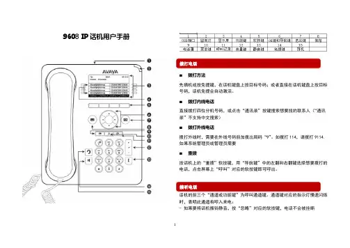
9608 IP话机用户手册⏹拨打方法先摘机或按免提键,在话机键盘上按目标号码;或者直接在话机键盘上按目标号码,话机免提会自动激活。
⏹拨打内线电话直接拨打四位分机号码,或点击“通讯录”按键搜索想要找的联系人(“通讯录”不支持中文搜索)⏹拨打外线电话拨打外线时,需要在外线号码前加拨出局码“9”。
如拨打114,请拨打9114.如果系统管理员或管理员需要⏹重拨按话机上的“重拨”软按键,用“导航键”中的左翻和右翻键选择想要拨打的电话,点击屏幕上“呼叫”对应的软按键即可呼出。
话机的前三个“通道或功能键”为呼叫通道键。
通道键对应的指示灯慢速闪烁时,表明此通道有呼入来电:- 如果要将话机振铃静音,按“忽略”对应的软按键,电话不会被挂断12- 如果要将呼叫转到语音信箱留言,按“至语音信箱”对应的软按键。
- 如要使用听筒接听电话,可以直接拿起听筒;也可以按免提键或耳机键分别使用耳机和免提接听来电。
在通话过程中,可以在听筒、免提、耳机间灵活切换。
⏹ 处理第二个来电9608话机为多通道话机,可以并发接受两个或更多呼入电话。
在通话过程中,第二个呼叫呼入时,对应的“呼叫通道键”的指示灯会慢闪。
可以直接点击此“呼叫通道键”,第一个呼叫将被保留,第二个呼叫将被接起。
通过点击“呼叫通道键”,可以在多个呼叫间切换。
还可以选择“导航键”的“上翻”、“下翻”按键,在屏幕上调出“忽略”“至语音信箱”。
点击“忽略”对应的软按键,将会停止振铃;点击“至语音信箱”对应的软按键,第二个呼叫将被转至语音信箱。
如果要将正在接听的电话转移到到其他分机,按“呼叫转接”软按键,此时对方处于被保留状态,将听到背景音乐。
可以选择以下两种转接模式: 1. 拨打目标分机号码,等待目标分机接听电话,然后挂机,完成转接;2. 拨打目标分机号码,听到振铃后,挂机,完成转接。
⏹ 召集会议如果您想与多人同时通话,可以按照如下步骤召开电话会议:1. 在与第一方通话过程中,按“电话会议”软按键,拨通第二个电话2. 第二个电话接听后,按“电话会议”软按键,此时三方都进入会议3. 如果还有其他与会者,按“电话会议”软按键,拨通第四方电话。
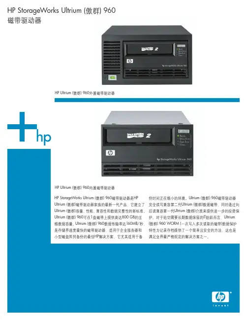
HP StorageWorks Ultrium (傲群) 960磁带驱动器是HP Ultrium (傲群)磁带驱动器家族的最新一代产品,它建立了Ultrium (傲群)容量、性能、兼容性和数据完整性的新标准。
Ultrium (傲群) 960可在1盘磁带上提供高达800 GB的压缩数据容量。
Ultrium (傲群) 960数据传输率达160MB/秒,是存储界速度最快的磁带驱动器,适用于企业服务器和小型磁盘阵列备份的最佳HP解决方案,它尤其适用于备份时间正在缩小的环境。
Ultrium (傲群) 960磁带驱动器完全读写兼容第二代Ultrium (傲群)数据磁带,同时通过向后读兼容第一代Ultrium (傲群)介质来提供进一步的投资保护。
对于迫切需要长期数据保留的IT组织而言,Ultrium (傲群) 960 WORM (一次写入多次读取的磁带)数据保护特性为记录存档提供了一个简单且安全的方法,这也是满足业界最严格规定的解决方案之一。
HP StorageWorks Ultrium (傲群) 960磁带驱动器HP Ultrium (傲群) 960外置磁带驱动器HP Ultrium (傲群) 960内置磁带驱动器主要特性•高容量磁带驱动器,按2:1的压缩比可在1盘磁带上存储800 GB (Ultrium (傲群) 960)的数据•高速数据传输率,按2:1的压缩比备份速度高达160 MB/秒•数据速率自动匹配根据服务器和网络环境自动调整磁带驱动器的读写速度,从而提高性能,减少机械磨损,延长磁带寿命•读写完全兼容其它厂商的Ultrium (傲群)磁带驱动器和介质•备有内置、外置、阵列模块及机架安装式机型•软加载特性自动定位数据磁带并可将其移到加载位置•先进的磁带引带捕捉设计确保磁带的故障安全装载•主动磁头清洗提供自动清洗功能,可延长磁头寿命,降低使用清洗带的次数•降低功耗,以最低的成本提供最高的可靠性•随机附带单服务器版HP OpenView Data Protector (下载许可)和Yosemite TapeWare XE (CD)备份软件及灾难恢复选项•HP单键灾难恢复(OBDR), 轻按一键即可恢复您的整个系统•附带HP StorageWorks Library and Tape Tools (LTT),协助安装、管理、优化性能及排除故障•支持WORM介质,提供一种简单、安全的数据存档方法,满足管理机构的要求客户受益•高容量:多种高容量磁带驱动器选项使您可以将所有数据存储到1盘磁带上•快速:高性能的数据传输可在减少对服务器和网络资源使用的同时,缩小备份窗口•经济:高容量与低介质成本相得益彰,提供超低的拥有成本,确保更快的投资回报•灵活:包括内置、外置、阵列模块和机架安装在内的多种磁带驱动器外形,可满足您服务器内外备份的需要•可靠:包括读写DRAM在内的高完整性数据路径为您的数据提供保护•兼容:已通过业界领先的主要的操作系统、备份软件和服务器上的鉴定/测试•轻松:支持单键灾难恢复(OBDR), 发生灾难时提供最轻松的数据恢复方法•可管理:通过Library and Tape Tools (LTT)提供出众的管理功能,使您的磁带驱动器便于安装、使用和支持•投资保护:制定具有吸引力的技术蓝图,提供更高容量和性能的磁带解决方案,同时可读写向后兼容前几代磁带驱动器•安全:支持WORM介质,为永久存储数据记录提供一种故障保险方法•选择:基于LTO技术开放标准,在不影响Ultrium(傲群)产品之间兼容性的前提下,为客户提供更多的厂商和解决方案选择2产品主要特点LTO Ultrium (傲群)技术线性开放磁带技术由存储业的三大领导者-HP、IBM和Seagate联合开发,他们结合了磁带技术上的突出优势,在现有最优秀技术的基础上,开发了一种全新的格式。
TL F 66109601 DM9601 Retriggerable One ShotJune19899601 DM9601Retriggerable One ShotGeneral DescriptionThese retriggerable one shots provide the designer withfour inputs two active high and two active low This permitsa choice of either leading-edge or trailing-edge triggeringindependent of input transition times When input conditonsfor triggering are met a new cycle starts and the externalcapacitor is rapidly discharged and then allowed to chargeagain The retriggerable feature allows for output pulsewidths to be expanded In fact a continuous true output canbe maintained by having an input cycle time which is shorterthan the output cycle time Retriggering may be inhibited bytying the Q output to an active low inputFeaturesY High speed operation input repetition rate l10MHzY Flexibility of operation optional retriggering lock-outcapabilityY Output pulse width range 50ns to%Y Leading or trailing edge triggeringY Complementary outputs inputsY Input clamping diodesY DTL TTL compatible logic levelsY Alternate Military Aerospace device(9601)is availableContact a National Semiconductor Sales Office Distrib-utor for specificationsConnection DiagramDual-In-Line PackageTL F 6610–1Order Number9601DMQB 9601FMQB DM9601J DM9601W or DM9601NSee NS Package Number J14A N14A or W14BFunction TableInputs OutputsA1A2B1B2Q QH e High Logic LevelH H X X L HL e Low Logic LevelX X L X L HX e Either Low orX X X L L H High Logic LevelL X H H L H u e Low to High LevelTransitionL X u Hv e High to Low LevelL X H uTransitionX L H H L He Positive PulseX L u H e Negative PulseX L H uH v H Hv v H Hv H H HC1995National Semiconductor Corporation RRD-B30M105 Printed in U S AAbsolute Maximum Ratings(Note)If Military Aerospace specified devices are required please contact the National Semiconductor Sales Office Distributors for availability and specifications Supply Voltage7V Input Voltage5 5V Operating Free Air Temperature RangeMilitary b55 C to a125 C Commercial0 to a70 C Storage Temperature Range b65 C to a150 C Note The‘‘Absolute Maximum Ratings’’are those values beyond which the safety of the device cannot be guaran-teed The device should not be operated at these limits The parametric values defined in the‘‘Electrical Characteristics’’table are not guaranteed at the absolute maximum ratings The‘‘Recommended Operating Conditions’’table will define the conditions for actual device operationRecommended Operating ConditionsSymbol ParameterMilitary CommercialUnits Min Nom Max Min Nom MaxV CC Supply Voltage4 555 54 7555 25V V IH High Level Input T A e b55 C2Voltage TA e0 C1 9T A e25 C1 71 8VT A e75 C1 6T A e125 C1 5V IL Low Level Input T A e b55 C0 85Voltage TA e0 C0 85T A e25 C0 90 85VT A e75 C0 85T A e125 C0 85I OH High Level Output Current b0 72b0 96mA I OL Low Level Output Current1012 8mA T A Free Air Operating Temperature b55125075 C Electrical Characteristics over recommended operating free air temperature range(unless otherwise noted)Symbol Parameter Conditions(Note3)MinTypMax Units (Note1)V I Input Clamp Voltage V CC e Min I I e b12mA b1 5V V OH High Level Output V CC e Min I OH e Max2 4VVoltage V IL e Max V IH e Min (Note4)V OL Low Level Output V CC e Min I OL e Max MIL0 4Voltage V IL e Max V IH e MinCOM0 45V(Note4)I IH High Level Input V CC e Max V I e4 5V60m A CurrentI IL Low Level Input V CC e Max MIL V IN e0 40V b1 6mA Current COM VIN e0 45V b1 6I OS Short Circuit V CC e Max MIL b10b40mA Output Current(Notes2and4)COM b10b40I CC Supply Current V CC e Max25mA Note1 All typicals are at V CC e5V T A e25 CNote2 Not more than one output should be shorted at a timeNote3 Unless otherwise noted R X e10k between PIN13and V CC on all testsNote4 Ground PIN11for V OL test on PIN6 V OH and I OS tests on PIN8 Open PIN11for V OL test on PIN8 V OH and I OS tests on PIN62Switching Characteristics at V CC e5V and T A e25 C(See Section1for Test Waveforms and Output Load)Symbol Parameter From(Input)Conditions Min Max Units To(Output)t PLH Propagation Delay Time Negative Trigger C L e15pFLow to High Level Output Input to C X e040nsTrue Output R X e5k Xt PHL Propagation Delay Time Negative TriggerHigh to Low Level Output Input to40nsComplement Outputt PW(MIN)Minimum True Output65ns Pulse Widtht PW Pulse Width R X e10k X3 083 76m sC X e1000pFC STRAY Maximum Allowable Pin13to GND50pF Wiring CapacitanceR X External Timing Resistor DM9625k XR X External Timing Resistor DM8650k X Operating Rules1 An external resistor R X and an external capacitor C X arerequired for operation The value of R X can vary between the limits shown in switching characteristics The value ofC X is optional and may be adjusted to achieve the re-quired output pulse width2 Output pulse width t PW may be calculated as follows t PW e K R X C X 1a0 7R X((for C X l103pF)K 0 34R X in k X C X in pF and t PW in ns(For C X k103pF see curve )3 R X and C X must be kept as close as possible to thecircuit in order to minimize stray capacitance and noise pickup If remote trimming is required R X may be split up such that at least R X(MIN)must be as close as possible to the circuit and the remote portion of the trimming re-sistor R k R X(MAX)b R X4 Set-up time(t1)for input trigger pulse must be l40ns(See Figure1)Release time(t2)for input trigger pulse must be l40ns (See Figure2)TL F 6610–2FIGURE1TL F 6610–3FIGURE25 Retrigger pulse width(see Figure3)is calculated as fol-lowst W e t PW a t PLH e K R X C X 1a0 7R X(a t PLHTL F 6610–4FIGURE3Typical‘‘K’’Coefficient Variation vs Timing Capacitance The multiplicative factor‘‘K’’varies as a function of the tim-ing capacitor C X The graph below details this characteris-ticTL F 6610–5 For further detailed device characteristics and output performance please refer to the NSC one-shot application note AN-3663Typical Performance CharacteristicsCapacitance For C X k 103pFTiming Resistance AndOutput Pulse Width vs TemperaturePulse Width vs Ambient Normalized OutputVoltagePulse Width vs Supply Normalized Output Operating Duty CyclePulse Width vsNormalized Output Resistance Pulse Width vs Timing Ambient TemperatureOutput Pulse Width vs TL F 6610–6Schematic DiagramTL F 6610–74Physical Dimensions inches(millimeters)14-Lead Ceramic Dual-In-Line Package(J)Order Number9601DMQB or DM9601JNS Package Number J14A14-Lead Molded Dual-In-Line Package(N)Order Number DM9601NNS Package Number N14A59601 D M 9601R e t r i g g e r a b l e O n e S h o tPhysical Dimensions inches (millimeters)(Continued)14-Lead Ceramic Flat Package (W)Order Number 9601FMQB or DM9601WNS Package Number W14BLIFE SUPPORT POLICYNATIONAL’S PRODUCTS ARE NOT AUTHORIZED FOR USE AS CRITICAL COMPONENTS IN LIFE SUPPORT DEVICES OR SYSTEMS WITHOUT THE EXPRESS WRITTEN APPROVAL OF THE PRESIDENT OF NATIONAL SEMICONDUCTOR CORPORATION As used herein 1 Life support devices or systems are devices or 2 A critical component is any component of a life systems which (a)are intended for surgical implant support device or system whose failure to perform can into the body or (b)support or sustain life and whose be reasonably expected to cause the failure of the life failure to perform when properly used in accordance support device or system or to affect its safety or with instructions for use provided in the labeling can effectivenessbe reasonably expected to result in a significant injury to the userNational Semiconductor National Semiconductor National Semiconductor National Semiconductor CorporationEuropeHong Kong LtdJapan Ltd1111West Bardin RoadFax (a 49)0-180-530858613th Floor Straight Block Tel 81-043-299-2309。
960CT9608Your personal entertainment studio Music, movies and photos on the moveEntertain yourself and others anywhere with music, videos, and more. Enjoy the convenience of a smooth sliding design and multimedia mix for crystal-clear music on the move, high-quality video recording, and 2 megapixel camera.Maximize your Multimedia Experience2 megapixel digital camera for crisp, vivid picturesHigh-quality video recorder captures life's excitementMP3 playerSD/MMC memory card slot for increased storage capacityDesigned for emotionFashionable sliding design for flexibility and functionLarge 262K color TFT display for vivid, colorful graphicsMMS video to record and share exciting multimedia messagesMP3 ringtones for a personalized and rich audio experienceAdvanced connectivityBluetooth for easy wireless connection to other devicesUSB connectivity to directly share data between phone and PCInfrared for close-range information exchangeHighlights2 megapixel cameraUse your 2 megapixel digital camera to enhance your photo experience with crisp, vivid pictures. The intuitive design and user interface allow you to easily take high-resolution photos of up to 1600 x 1200 pixels to use as wallpaper for your phone display; send from your phone via MMS, Bluetooth, or infrared; or print and share.High-quality video recorderCapture excitement at the speed of life wherever you go with this intuitively designed, high-quality video recorder with 30 frames-per-second recording capacity that works like a premium camcorder.MP3 playerYour mobile phone with MP3 player enables you to enjoy high quality music all in one device. You can transfer your favorite MP3 hits and listen to them on the go.SD/MMC memory card slotThe SD/MMC memory card slot gives you theadditional storage capacity to enjoy morepictures, videos, and music simply by insertingan SD/MMC card into the built-in memory cardslot of your phone.Fashionable sliding designThe sliding design provides a fashionable,functional mobile phone experience,displaying a large screen and keypad whenfully opened, and taking up minimum spacewhen closed.Large 262K color TFT displayPut the fun and excitement of the most vividand colorful graphics and photos right at yourfingertips with the large 262K color display thatfeatures excellent image quality and responsetime.MMS videoMMS video lets you record and share excitingmultimedia messages with your friends andfamily just by attaching a video clip.MP3 ringtonesMP3 ringtones let you choose the sounds ofyour favorite songs for a personalized and richaudio experience just by selecting an MP3 fileto set as your ringtone.BluetoothBluetooth technology allows easy wirelessconnection to other Bluetooth devices on thego. Enrich your mobile multimedia experienceby using your Bluetooth headset, easily andquickly sharing files or synchronizing personaldata to and from your phone.USB connectivityUse a standard USB cable to directly andeasily transfer pictures, videos, music files, andother data between your phone and PC.InfraredInfrared is the simplest wireless technology forinformation exchange at close range, allowingeasy sharing of images, backgrounds, songs,and phonebook contacts with friends andfamily and enabling wireless access to theinternet through your PC.SpecificationsDimensionsHandset dimensions: 95 x 47.5 x 23 mm Handset weight: 95 gHandset volume: 90 ccForm Factor: SliderAntenna: IntegratedHandset Color: Silver Sound, Titanium Tune, White WidePicture/DisplayMain Display Technology: TFTMain Display Colors: 262KMain Display Resolution: 176x220 pixel Lines of text: up to 9Video CapturingImage sensor type: CMOSImage sensor resolution: 2M pixelVideo resolution: CIF, QCIFVideo format: 3GP, H.263Frame rate: 30 fpsVideo PlaybackResolution (pxl): 176x144, 352x288 Compression formats: H.263, 3GPFrame rate (fps): 15, 30Still Picture CapturingCamera: IntegratedImage sensor type: CMOSPicture resolution: VGA (640x480), QVGA (320x240), QQVGA (120x160), SVGA(800x600), 1M (1280x960), 2M (1600x1200) Digital zoom: continuous upto x8Picture quality: Normal, Fine, Superfine Picture Mode: Night mode, Self-timer mode, Multi-shotPreview frame rate: 30 frames/second Picture file format: JPEGSpecial effects preview mode: Grey scale, Sepia, Negative color, Blue effect, Crayon, Sketch, Oil, Blackboard, WhiteboardSoundRingers: MP3 ringer, Polyphonic (64 tones), Voice memo ringerAudio CapturingVoice recording: Yes, AMR Audio PlaybackAudio supported formats: AMR, Midi, MP3,SMAF, AACStorage MediaBuilt-in memory (RAM): 32User memory: 10 MBMultimedia ApplicationsMemory Card Access: SD/MMC card slotNetwork FeaturesMessaging: Concatenated SMS (Long SMS), E-mail, EMS / release 4, MMS,MultimediaMessage Service, Predefined messages(SMS,MMS), SMS CB (Cell Broadcast), SMS(Short Message Service), SMS multi-targetServices: OTA provisioning (WAP,MMS), SIMToolkit / Release 99, WAP Browser Openwave6.1, WAP 2.0, DRM (combined delivery)GPRS (Rx+Tx): Class 10 (4+2), Class BVoice Codec: FR/EFR/AMR/HRGSM band: 900, 1800, 1900 MHzConvenienceSpeech Recognition: Conversation Recording,Voice Command, Voice Dial, Voice MemoEase of Use: Dedicated Headset plug, HotKeys, Screen Saver Digital Clock, Vibra Alert,In-flight mode, SoftkeysEase of Navigation: Animated Color Matrix,Active SliderButtons and controls: 4-way navigation keyand enter, Customized hot key, Camera key,Side keysGames and applications: Agenda, AlarmClock, Calculator, Calendar, Euro Converter,Java MIDP 2.0ConnectivityHeadset: Via bottom connectorSerial connections: USB-Bottom connectorcableModem Capabilities: CSD (Voice, Data), GPRS,SMSPC Link: USB 1.1Synchronisation PC organizer: Lotus Notes,MS OutlookWireless connection: Bluetooth, InfraredAccessoriesStandard Package Includes: Battery, CD ROM(Mobile Phone Tools), Charger, Handset,International Guarantee, SAR informationleaflet, User Manual, USB data cable, Deluxestereo headsetOptional accessories: Car cradle, Carry case,Cigarette lighter adapter, Necklace, Universalcar kit, Bluetooth headset, Bluetooth car kitPowerTalk time: up to 4 hrsStandby time: up to 270 hrsCharging time: less than 4.5 hrBattery Capacity: 980 mAhBattery Type: Lithium-ionElectrical Enhancements: Back-up batteryBattery saving manager: Auto switch on/off© 2022 Koninklijke Philips N.V.All Rights reserved.Specifications are subject to change without notice. Trademarks are the property of Koninklijke Philips N.V. or their respective owners.Issue date 2022‑06‑03 Version: 2.0.412 NC: 9961 400 04771 。
数据手册 FUJITSU PRIMERGY BX960 S1 四路刀片服务器Page 1 of 5 /cn/services/hardware/servers/primergy/数据手册FUJITSU PRIMERGY BX960 S1 四路刀片服务器兼备灵活性和高可扩展性FUJITSU PRIMERGY BX 刀片服务器FUJITSU PRIMERGY BX 刀片服务器是目前以及未来数据中心解决方案的理想选择,以最小的机架空间、最低的功耗和最少的电缆连接实现高性能和最大化冗余。
FUJITSU PRIMERGY BX 系列能够在不同机箱之间共享组件,因而可快速轻松应对多变的业务需求,毫不费力地完成布线或添加管理软件所需存储器和服务器刀片的添加。
用户可使用同样的应用程序,依靠同样的服务器和存储组件,连接至同样的网络。
FUJITSU PRIMERGY BX 刀片服务器具有很高的灵活性,通过一个集中冗余管理工具实现对系统的全面管理,确保将管理所需的时间和精力降至最低,让用户远离耗时的琐碎工作。
我们采用按单定制流程,根据用户的独特需求提供完整、经过测试的解决方案,满足未来用户的业务拓展需求。
FUJITSU PRIMERGY BX960 S1刀片服务器 FUJITSU PRIMERGY BX960 S1刀片服务器采用新一代英特尔®至强®处理器,最高配置两条线程8个内核。
配合使用QuickPath 架构和片上内存控制器,刀片服务器性能可获大幅提升。
FUJITSU PRIMERGY BX960 S1刀片服务器最多可配备4颗处理器,32个DDR3 RDIMM 主内存模块和2个板载双通道英特尔®82599 10Gb 以太网控制器;作为全高刀片服务器(单宽),还配备了适用于VMware ESXi 的USB 闪存模块,多达2个SSD 数据介质和4个夹层I/O 卡。
处理器性能、主内存容量和I/O 带宽的完美结合令FUJITSU PRIMERGY BX960 S1刀片服务器成为hypervisor 虚拟化解决方案的理想整合平台,能够高效、可靠地满足中型和大型数据库管理系统的高端要求。
用戶使用手冊直流可編程電子負載型號IT8518系列IT8518B/IT8518C/IT8518E/IT8518F第一章快速入門 (6)1.1開機自檢 (6)1.1.1介紹 (6)1.1.2自檢步驟 (6)1.1.3如果負載不能啟動 (6)1.2前面板介紹 (7)1.3後面板介紹 (8)1.4VFD指示燈功能描述 (8)1.5鍵盤介紹 (9)1.6快速功能鍵 (9)1.7功能表操作 (10)1.8選件和配件 (11)第二章技術規格 (12)2.1主要技術參數 (12)2.2補充特性 (13)第三章面板操作 (13)3.1基本操作模式 (13)3.1.1定電流操作模式(CC) (13)3.1.2定電阻操作模式(CR) (14)3.1.3定電壓操作模式(CV) (14)3.1.4定功率操作模式(CW) (14)3.2動態測試操作 (15)3.2.1連續模式(CONTINUOUS ) (15)3.2.2脈衝模式(PULSE) (15)3.2.3觸發模式(TRIGGER) (15)3.3順序操作(LIST) (16)3.4觸發操作(TRIGGERED OPERATION) (16)3.5輸入控制 (17)3.5.1 短路操作(SHORT) (17)3.5.2 輸入開關操作 (17)3.6電子負載可操作範圍 (17)3.7保護功能 (17)3.7.1 過電壓保護(OV) (17)3.7.2 過電流保護(OC) (18)3.7.3 過功率保護(OW) (18)3.7.4 輸入極性反接 (18)3.7.5 過溫度保護(OH) (18)3.8遠端測試功能 (18)3.9存取操作 (19)3.10電池放電測試操作 (19)3.11V ON V OFF 操作 (20)第四章安裝 (21)4.1驗貨 (21)4.2清潔 (21)4.3尺寸圖 (21)4.3輸入連接部分的安裝 (22)第五章應用範例 (23)5.1操作模式實例 (23)5.1.1定電流操作I-Set(設定一個從0到限定電流範圍的定電流值) (23)5.1.2定功率操作P-Set (設定一個從0到限定功率範圍的定功率值) (23)5.1.3 定電阻操作R-set (設定一個從0.1Ω到4000Ω範圍內定電阻值) (23)5.1.4 定電壓操作V-set (設定一個從0.1V到限定電壓範圍的定電壓值) (23)5.1.5 IN ON/OFF輸入設定 (23)5.2動態測試功能 (24)5.2.1動態測試參數的設定 (24)5.2.2動態測試操作 (24)5.3順序操作 (25)5.4快速調用功能 (26)5.5自動測試功能 (27)5.5.1編輯測試檔 (27)5.5.2 快速取出測試檔 (28)5.5.3自動測試 (28)5.6電壓量程和電流量程的快速切換方法 (29)第六章負載通訊介面參考 (29)6.1通訊模組簡介 (29)6.2電子負載與PC間的通訊 (30)安全請勿自行在儀器上安裝替代零件,或執行任何未經授權的修改。
IT系列红外测温仪精品文档目录1 概述2 技术参数3 外形结构3.1 IT-5外形结构3.1 IT-6/ITL-500外形结构及面板说明3.2 IT-8外形结构及面板说明4 选型表4.1 ITL-500选型表4.2 IT-5选型说明4.2 IT-6/8选型表5 使用5.1 安装5.2 引出线定义5.3 输出选择5.4 瞄准及距离系数精品文档1 概述IT红外测温仪分为,ITL-500,IT-5,IT-6,IT-8四大种系列产品,各系列产品各具特色,可分别适用于各种不同的场合。
ITL-500用于从负温度起到1200℃的温度测量,IT-5用于安装空间小,测量目标小的场合,IT-6是一款性价比高,适应性很强的测温仪,可广泛运用于金属加工,科研试验等领域。
IT-8是IT红外测温仪的高端产品,适合有色金属加工,例如铝材,铜材等。
IT各系列红外测温仪产品均具有激光瞄准功能,安装使用方便,温度测量范围覆盖了-25℃-3000℃,各系列产品可在其有效的测量范围内自由分段。
可以满足用户各种温度测量的需求。
IT红外测温仪采用优异的光学结构及工艺;电路处理单元采用32bit(部分产品使用16bit)MCU。
严谨的制作工艺及严格的质量管理,使得本测温仪的测量精度和重复性有了很好的保证。
非接触测量的特性,使得IT红外测温仪可广泛运用于运动物体,带电导体,真空环境或其他特殊要求的目标进行非接触温度检测。
IT红外测温仪可广泛应用于食品,塑料加工,铸造、粉末冶金、轧钢、电力、化工、玻璃、陶瓷生产、热处理,中高频感应加热,线材生产,焦化,热压烧结、焊接等行业。
选型使用推荐及各系列产品适用的行业:ITL-500该型号测温仪由于波长,温度范围的特点,适用于温度较低,常规材料辐射率比较接近1的场合,行业包括感应加热的电磁线高频烧结,塑料,化工,电机热安装等行业IT-5安装空间狭窄或者对精确瞄准及快速响应要求较高的场合,例如高频焊接,中频钎焊等行业,目前较典型的如全自动焊齿机IT-6中频长短棒料透热,窑炉,中频钎焊,轧钢,玻璃,陶瓷,粉末冶精品文档金,热压烧结,精密铸造等行业IT-8PC钢棒热处理,不锈钢热处理,铝材加热,挤压,熔铸,铜材加热,单晶硅生长,多晶硅铸造等行业2 技术参数:1、温度范围:IT-5 400~1200℃IT-6/8 260℃~3000℃(标准分段见4.2)ITL-500 0~1000℃(标准分段见4.1)2、基本误差:IT-5/6/8 0.5(±0.5%)或0.2(±0.2%)ITL-500 1.5(±1.5%)3、测头尺寸:IT-5 φ25×160mmIT-6/ITL-500 φ45×135mmIT-8 φ50×150mm4、距离系数: IT-5 140:1IT-6/8 150:1ITL-500 50:15、测量距离:0.2m~5m6、可测最小目标:IT-5/6/8 φ2mm(300mm)ITL-500 φ6mm (350mm)7、发射率:IT-5 不可调IT-6/ITL-500 1.0、0.9、0.8、0.7四档发射率可调IT-8 0.01~1.00 可调8、响应波长范围:IT-5 1.1~1.7IT-6/8 0.7~1.7µmITL-500 8~14µm9、响应时间:IT-5/6/8小于5msITL-500小于50ms10、温度分辨率:0.5℃11、重复精度:±0.2%精品文档12、模拟量输出:0-5VDC 或4-20mA13、开关量输出:1组43V/1A(可选,只有IT-8)14、通讯接口:RS485(可选,IT-5不具备)15、工作电源:IT-6/8/ITL-500 ±12VDC 或24VDCIT-5 12VDC16、重量:IT-5 0.25KGITL-500/IT-6 0.5KGIT-8 0.6KG17、工作环境:0~60℃,相对湿度不大于90%3 外形结构3.1 IT-5 外形结构3.2 IT-6/ITL-500 外形结构及面板说明面板及说明:精品文档①激光瞄准和发射率调整按键,按该键,激光瞄准有效,更多关于瞄准和发射率调整介绍请查看5.4(瞄准)和5.5(参数设置)②红外测温仪工作状态指示灯,该指示灯的状态对应当前仪器发射率参数;③电信号接口,根据不同型号红外测温仪及输出要求不同有4芯、5芯、6芯等不同的接口。