HM628512CLRRI-7中文资料
- 格式:pdf
- 大小:97.70 KB
- 文档页数:17
XC2130用戶手冊2017 年 11 月機器型式:7527機種:496內容安全資訊 (7)瞭解印表機 (9)尋找印表機相關資訊 (9)選取印表機放置地點 (10)印表機配置 (11)瞭解掃描器的基本功能 (12)使用自動送件器和掃描器玻璃面板 (12)瞭解印表機控制面板 (13)使用印表機控制面板 (13)瞭解主畫面 (13)瞭解「睡眠」按鈕和指示燈的顏色 (15)使用觸控式螢幕按鈕 (15)設定及使用主畫面應用程式 (17)尋找電腦的 IP 位址 (17)尋找印表機的 IP 位址 (17)存取 Embedded Web Server(內嵌式 Web 伺服器) (17)自訂主畫面 (18)瞭解不同的應用程式 (18)啟動主畫面應用程式 (19)設定「遠端操作面板」 (22)匯出及匯入配置 (23)其他印表機設定 (24)安裝內接式選購品 (24)安裝硬體選購品 (30)連接電纜 (33)設定印表機軟體 (34)網路功能 (35)驗證印表機設定 (38)載入紙張和特殊材質 (39)設定紙張尺寸和類型 (39)配置 Universal(通用尺寸)紙張設定 (39)載入 250 張和 550 張紙匣組件 (39)載入手動輔助式送紙器 (42)載入 650 張雙層紙匣組件 (43)將材質載入多用途送紙器 (44)連結及解除連結紙匣組件 (46)紙張和特殊材質指南 (49)使用特殊材質 (49)紙張指引 (52)支援的紙張尺寸、類型和重量 (55)列印 (58)列印表單 (58)列印文件 (58)從快閃儲存碟列印 (60)從行動裝置列印 (62)列印機密工作和其他保留工作 (63)列印資訊頁 (64)取消列印工作 (65)複印 (66)進行複印 (66)複印相片 (67)複印在特殊材質上 (67)利用印表機控制面板建立複印快捷鍵 (68)自訂複印設定 (69)在複印文件上放置資訊 (73)取消複印工作 (74)瞭解複印選項 (75)以電子郵件寄送 (79)設定印表機電子郵件功能 (79)建立電子郵件快捷鍵 (79)以電子郵件寄送文件 (80)自訂電子郵件設定 (82)取消電子郵件 (82)瞭解電子郵件選項 (83)傳真 (86)設定印表機傳真功能 (86)傳送傳真 (101)建立快捷鍵 (104)自訂傳真設定 (104)取消外送的傳真 (106)保留與轉發傳真 (106)瞭解傳真選項 (107)掃描 (110)使用 Scan to Network(掃描至網路) (110)掃描至 FTP 位址 (110)掃描至電腦或快閃儲存碟 (112)瞭解掃描選項 (114)瞭解印表機功能表 (117)功能表清單 (117)耗材功能表 (118)紙張功能表 (118)報告功能表 (126)網路/連接埠 (128)安全性功能表 (136)設定功能表 (140)節省金錢並注重環保 (186)節省紙張和碳粉 (186)省電 (186)回收利用 (190)固定印表機 (191)使用安全鎖功能 (191)揮發性聲明 (191)清除揮發性記憶體 (192)清除非揮發性記憶體 (192)清除印表機硬碟記憶體 (193)配置印表機硬碟加密 (193)尋找印表機安全資訊 (194)維護印表機 (195)存放耗材 (195)清潔印表機 (195)檢查零件及耗材狀態 (197)預估剩餘頁數 (197)訂購耗材 (197)更換耗材 (200)移動印表機 (219)管理印表機 (220)尋找進階網路功能及管理者資訊 (220)檢查虛擬顯示幕 (220)設定電子郵件警示 (220)檢視報告 (220)從 Embedded Web Server(內嵌式 Web 伺服器)配置耗材通知 (221)修改機密列印設定 (221)複製印表機設定至其他印表機 (222)回復出廠預設值 (222)清除夾紙 (224)避免夾紙 (224)識別夾紙位置 (225)標準出紙槽中發生夾紙 (226)前門中發生夾紙 (227)紙匣組件中的夾紙 (229)紙張夾在手動輔助式送紙器中 (230)多用途送紙器中的夾紙 (231)自動送稿器中發生夾紙 (232)疑難排解 (233)瞭解印表機訊息 (233)解決印表機問題 (248)解決列印問題 (253)解決複印問題 (278)解決傳真問題 (281)解決掃描器問題 (286)解決主畫面應用程式問題 (290)Embedded Web Server(內嵌式 Web 伺服器)未開啟 (291)聯絡客戶支援中心 (292)注意事項 (293)產品資訊 (293)版本注意事項 (293)耗電量 (299)索引 (302)安全資訊請將電源線連接到本產品附近具有適當等級且妥善接地的電源插座,而且必須易於使用。
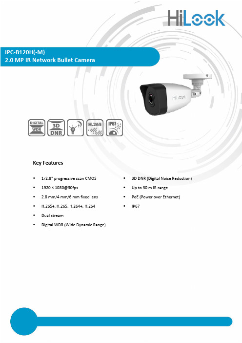
Key Features• 1/2.8" progressive scan CMOS • 3D DNR (Digital Noise Reduction) • 1920 × 1080@30fps• Up to 30 m IR range • 2.8 mm/4 mm/6 mm fixed lens • PoE (Power over Ethernet) • H.265+, H.265, H.264+, H.264 •IP67• Dual stream•Digital WDR (Wide Dynamic Range)CameraImage Sensor 1/2.8" progressive scan CMOSMin. Illumination Color: 0.01 Lux @(F1.2, AGC ON), 0.028Lux @ (F2.0, AGC ON) Shutter Speed 1/3 s to 1/100, 000 sSlow Shutter YesAuto-Iris NoDay &Night IR cut filterDigital Noise Reduction 3D DNRWDR Digital WDRAngle Adjustment (Bracket) Pan: 0° to 360°, tilt: 0° to 180°, rotation: 0° to 360°LensFocal length 2.8 mm, 4 mm, 6 mmAperture F2.0Focus NoFOV 2.8 mm, horizontal FOV 103°, vertical FOV 59°, diagonal FOV 118°4 mm, horizontal FOV 86°, vertical FOV 46°, diagonal FOV 102°6 mm, horizontal FOV 54°, vertical FOV 30°, diagonal FOV 62°Lens Mount M12IRIR Range Up to 30 m Wavelength 850 nm Compression StandardVideo Compression Main stream: H.265/H.264Sub stream: H.265/H.264/MJPEGH.264 Type Baseline Profile/Main Profile/High Profile H.264+ Main stream supportsH.265 Type Main ProfileH.265+ Main stream supportsVideo Bit Rate 32 Kbps to 8 MbpsSmart Feature-setRegion of Interest 1 fixed region for main stream and sub-stream ImageMax. Resolution 1920 × 1080Main Stream Max. Frame Rate 50Hz: 25fps (1920 × 1080, 1280 × 960, 1280 × 720) 60Hz: 30fps (1920 × 1080, 1280 × 960, 1280 × 720)Sub-stream Max. Frame Rate 50Hz: 25fps (640 × 480, 640 × 360, 320 × 240) 60Hz: 30fps (640 × 480, 640 × 360, 320 × 240)Image Enhancement BLC, 3D DNRImage Setting Saturation, brightness, contrast, sharpness, AGC, white balance adjustable by client software orweb browserDay/Night Switch Auto, scheduledNetworkAlarm Trigger Motion detection, video tampering alarm, illegal loginProtocols TCP/IP, ICMP, HTTP, HTTPS, FTP, DHCP, DNS, DDNS, RTP, RTSP, RTCP, NTP, UPnP, SMTP, IGMP,802.1X, QoS, IPv6, UDP, BonjourGeneral Function Anti-flicker, heartbeat, mirror, password protection, privacy mask, watermarkFirmware Version 5.5.2SpecificationAvailable ModelsIPC-B120H (2.8/4/6 mm), IPC-B120H-M (2.8/4 mm)APIONVIF (PROFILE S, PROFILE G), ISAPI Simultaneous Live View Up to 6 channelsUser/Host Up to 32 users3 levels: Administrator, Operator, and User Client HiLookVision PC Client, HiLookVision AppWeb Browser IE8+, Chrome 41.0-44, Firefox 30.0-51, Safari 8.0-11InterfaceCommunication Interface1 RJ45 10M/100M self-adaptive Ethernet portGeneralOperating Conditions -30 °C to 50 °C (-22 °F to 122 °F), humidity: 95% or less (non-condensing) Power Supply12 VDC ± 25%, 5.5 mm coaxial power plug PoE (802.3af, class 3)Power Consumption and Current 12 VDC, 0.4 A, Max: 5 WPoE: (802.3af, 36 V to 57 V), 0.2 A to 0.13 A, Max: 7 W Protection LevelIP67MaterialWithout –M model:Front cover: metal, camera body: plastic, bracket: plastic -M model:Front cover: metal, camera body: metal, bracket: metal DimensionsCamera: Ø 70 mm × 191.3mm (Ø 2.7" × 7.5")With package: 216 mm × 121 mm × 118 mm (8.5" × 4.8" × 4.6") WeightWithout –M model:Camera: Approx. 280 g (0.6 lb.)With package: Approx. 530 g (1.2 lb.) -M model:Camera: Approx. 395 g (0.9 lb.)With package: Approx. 631 g (1.4 lb.)Dimensions191.3 mm (7.53" )66.7 m m (2.63 " )(2.76 " )120°AccessoryHIA-J101 Junction Box。

Product PictureShaver series 5000SteelPrecision bladesPower Adapt sensor360-D Flexing headsIntegrated pop-up trimmerS5579/71Powerful shave, gentle on skinwith SkinIQ T echnologyThe Philips Series 5000 delivers a powerful shave, cutting now even more hair per stroke*. Equipped with advanced SkinIQ technology, the shaver senses and adapts to your hair density, for improved skin comfort.A powerful shaveMore cutting performance in every strokeFollows the contours of your faceGuides hair into the optimal cutting positionSkinIQ technologyA shaver with the power to tame beardsFor a convenient shavePowerful cleaning pod for maintenance and hygieneChoose a convenient dry or refreshing wet shaveEven-up your mustache and sideburns60 minutes of shaving from a 1-hour chargeFully charged in one hourThe electric shaver with an Eco passportA more intuitive shaving experienceWet & Dry electric shaver S5579/71 Highlights SpecificationsSteelPrecision bladesPowerful yet gentle, the 45 self-sharpening SteelPrecision blades on this Philips shaver complete up to 90,000 cutting actions per minute, cutting more hair per stroke** for a clean, comfortable finish.Power Adapt sensorThe electric shaver has intelligent facial-hair sensor that reads hair density 125 times per second. The technology auto-adapts cutting power for an effortless and gentle shave.360-D Flexing headsDesigned to follow the contours of your face, this Philips electric shaver has fully flexible heads that turn 360° for a thorough and comfortable shave.Hair-Guide precision headsThis new shape precision shaver is enhanced with hair guiding channels for optimal cutting and skin comfort.Cable-free Quick Clean Pod10x more effective than cleaning with water**, the powerful cleaning pod thoroughly cleans and lubricates your shaver in just 1 minute. Using it helps maintain shaver performance and increase hygiene.Shave wet or dryA wet and dry shaver that adapts to yourpreference. Choose a convenient dry shave, orpair with your favourite foam or gel for arefreshing wet shave.Pop-up trimmerRefine and define your mustache andsideburns with the pop-up trimmer—andcomplete your look with ease.60 minutes of cordless shavingA shaver for at home or on-the-go. Get 60minutes of shaving time from a 1-hour charge,or plug it in for instant and continuous power.1-hour charging timeFully charge your Philips shaver in just 1 hourwith the powerful and energy efficient lithium-ion battery. In a hurry? Plug in your shaver for 5minutes and get enough power for 1 full shave.Sustainable shaving innovationAt Philips, we drive sustainability in all aspectsof product creation. With shaving bladesproduced using 100% renewable electricityand packaging made with recyclable materials,all shavers come with an Eco passport.LED displayYou can easily see how much power is left withthe 3-level LED display. Your Philips shavernot only tells you when it's time to charge, italso has indicators for locking, cleaning andreplacing the head.Shaving PerformanceShaving system: SteelPrecision bladesContour following: 360-D Flexing headsSkinIQ technology: Power Adapt sensorEase of useWet & Dry: Wet and dry useDisplay: LED display, Battery level indicator,Travel lockCleaning: One-touch open, Fully washableDesignHandle: Rubber gripColor: Electric BlueShaving heads: AngularPowerRun time: 60 minutesCharging: 1 hour full charge, 5 min quickchargeAutomatic voltage: 100-240 VStand-by power: 0.04 WMax power consumption: 9 WBattery type: Li-ionService2-year warrantyReplacement head SH71: Replace every 2 yrswith SH71AccessoriesQuick Clean Pod: 1 cartridge included, YesIntegrated pop-up trimmerMaintenance: Cleaning brushTravel and storage: Travel case* Tested versus Philips Series 3000.* * Comparing shaving debris after using cleaning fluidvs. water in the cartridge© 2022 Koninklijke Philips N.V.All Rights reserved.Specifications are subject to change without notice. Trademarks are the property of Koninklijke Philips N.V. or their respective owners.Issue date 2022‑03‑31 Version: 3.0.1。
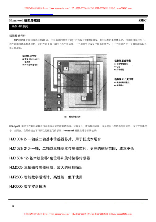
磁阻敏感元件Honeywell在磁阻敏感元件(图3),由长而薄的玻莫合金(一种铁镍合金)薄膜制成。
利用标准的半导体工艺,将薄膜附着硅片上。
四个磁阻组成惠斯通电桥。
同时在硅平面上制作了两个电流带,一个用来置位或复位输出的极性、另一个用来产生一个偏置磁场以补偿环境磁场。
Honeywell提供了在场地磁场范围内非常灵敏的磁阻传感器。
可测量几十微高斯的磁场,这是霍尔元件所不能做到的。
由于它的体积小,全固态,在某些场合下可以取代磁通门传感器。
Honeywell磁阻传感器家族包括:HMC1001/2-一轴或二轴基本传感器芯片,用于低成本场合HMC1021/2/3-一轴,二轴或三轴基本传感器芯片,更宽的磁场范围,成本更低HMC1501/12-基本线位移/角位移和旋转位移传感器HCM2003-三轴磁传感器模块,放大的模拟输出HMR2300-智能数字磁场计,高性能,便于使用HMR3000-数字罗盘模块特性·带微处理器的智能传感器·低成本,使用方便-一插即用·量程:±2Gauss,分辨率67μGauss·采样速度可选:10~157采样点/秒·三轴数字量输出:BCD码,ASCⅡ码或二进制码·9600或19.6K波特率可选择·符合RS-485标准,总线上连接多个单元·符合RS-232标准进行单点读数应用·航空用和船用罗盘·车辆遥感检测(侧滚/俯仰/偏航) ·过程控制·实验室仪器·异常检测·交通车辆检测·保安系统概述霍尼韦尔公司生产的三轴智能数字磁场计(HMR)可检测磁场的强度和方向,并与计算机直接通讯,输出X、Y、Z三个轴的分量。
用三个独立的桥路定向检测磁场的X、Y、Z轴的分量,电桥输出端相应电压的变化通过一个16位AD转换器转换为数字量。
可输入命令组态数据采样速率、输出格式、平均读数和零点偏移(见表1)。

HMA-I(h)录音卡用户手册——北京音视讯达科技工作室HMA-I(h)录音卡用户手册(北京音视讯达科技工作室)联系人: 支先生业务QQ: 417334344E-Mail: zzsir2000@网 站: HMA-I(h)录音卡用户手册——北京音视讯达科技工作室目录:1. 概述 (3)1.1 应用领域 (3)1.2 主要功能特点 (3)1.3 产品型号 (4)2. 电气特性 (5)2.1 极限参数 (5)2.2 直流特性 (5)2.3 封装尺寸 (5)2.4 接口定义 (6)3. 录音卡与测试板实物 (8)3.1 录音卡实物说明 (8)3.2测试板实物说明 (9)4. 计算机管理软件 (10)附录1:常见问题解答 (12)HMA-I(h)录音卡用户手册——北京音视讯达科技工作室1. 概述HMA-I(h)系列录音卡是用自主研究的音频压缩算法开发的音频类模块化产品,具有音质好、体积小、性价比高等优点,既可以嵌入到用户产品中实现其语音功能,也可以直接加上电源、喇叭、键盘、音量调整电阻后作为独立产品使用,内置3W功放(PWM输出可直接驱动喇叭)。
本系列支持6KHz—16KHz四种音频采样频率,音频数据最多可存储约35分钟@16KHz或93分钟@6KHz,满足很多行业和领域的语音应用要求。
本手册全部修改、发布和所有权归北京音视讯达科技工作室所有,我工作室有权在不做通知的情况下进行变更,请关注我工作室网站或联系我们以获得最新资料。
1.1 应用领域¾语音报警¾公交语音报站、电梯语音提示¾智能仪器仪表¾语音智能互动玩具¾儿童电子琴、各种电子乐器(需MIDI音库)¾儿童语音早教玩具¾语音贺卡、铃声¾语音相册、宣传册¾GPS语音导航¾语音电子书¾语音袖珍讲解器(展会、旅游景点等)¾语音录放、自动答录¾户内/户外语音广告¾其他使用语音录制、播放的领域1.2 主要功能特点¾录音卡为高品质音频播放模块,支持6K、8K、11.025K、16KHz四种音频采样频率,配合16位的D/A使音质远超单芯片方案,达到广播级的优秀音质。


公司简介深圳市信华翰科技有限公司成立于2006年,注册资金500万,办公室位于深圳市商业中心,华强北商圈的国际科技大厦11楼,办公面积320平方。
是Honeywell 金牌代理商、Newland 新大陆金牌代理商、摩托罗拉讯宝SYMBOL 战略合作伙伴、优尼泰克授权服务商。
我司共代理有十几个品牌的条码设备,为客户提供优质丰富的条码相关产品和系统集成专业服务。
扫描网是深圳市信华翰科技有限公司斥资100万打造的扫描枪的网上商城。
信华翰为了让中国的条码事业走得更好更快,让大众都能享受条码带来的便利,特此为全国商户带“”来质优价廉的各类扫描枪,扫描网所售的所有扫描枪均是厂家授权,均经过三测(出厂检测,到货检测,出货检测)的优良产品。
PIRY ins zebexOPTICONT S C合作伙伴Honeywell深圳市信华翰科技有限公司SHENZHEN XIN HUA HAN SCIENCE AND TECHNOLOGY CO.,LTD.地址:深圳市福田区深南中路3007号国际科技大厦11楼电话****************************;传真**************展销部:深圳市华强北赛格大厦7106室网址:服务热线:新大陆HR1030手持式扫描枪北京意锐RC532二维码扫描平台 摩托罗拉C11一维扫描枪霍尼韦尔1900GHD二维码扫描枪PIRYinsHoneywell如何正确使用条码阅读器:1、在条码阅读器和条码保持一定的倾角,以达到最佳效果。
2、在条码阅读器和条码间的角度不能为90度,否则不能正常读码。
3、务必让条码被完整扫描,确定阅读器能正确扫读。
介绍说明:该条码扫读设备为计算机信息系统提供精确,易用和快速的数据录入和存入的完备的解决方案。
本产品提供完整的接口方式以适应各类主机的计算机系统包括:KeyboardWandRS-232Dual RS-232USBOTHERS所有译码器的参数设定都可通条码的扫描来完成,并保存在存储记忆体中,在关闭电源后仍保留设置。
HM628128D系列RAM中文数据手册一、产品概述HM628128D系列RAM是一种高性能的静态随机存取存储器(SRAM)。
它采用了128K×8位的存储结构,具有快速的读写速度和低功耗特性。
该系列RAM广泛应用于计算机、通信设备、工业控制系统等领域。
二、产品特性1. 存储容量大:HM628128D系列RAM具有128K×8位的存储容量,能够满足大部份应用需求。
2. 高速读写:该系列RAM的读写速度非常快,能够提供高效的数据存取和处理能力。
3. 低功耗:HM628128D系列RAM采用了低功耗设计,能够节省能源并延长设备使用时间。
4. 高可靠性:该系列RAM具有良好的抗干扰性和稳定性,能够在各种恶劣环境下正常工作。
5. 广泛应用:HM628128D系列RAM适合于计算机、通信设备、工业控制系统等多个领域,具有广泛的应用前景。
三、产品规格1. 存储容量:128K×8位2. 工作电压:3.3V3. 工作温度范围:-40℃至85℃4. 读写周期时间:10ns5. 封装形式:DIP、SOP、TSOP等多种封装形式可选四、引脚定义HM628128D系列RAM的引脚定义如下:1. 地址线(A0-A16):用于指定存储器中的地址。
2. 数据线(D0-D7):用于传输数据。
3. 读使能(OE):使能读操作。
4. 写使能(WE):使能写操作。
5. 片选(CE):选择芯片。
五、应用案例1. 计算机内存:HM628128D系列RAM可作为计算机的内存模块,提供高速的数据存储和读写能力,提升计算机的运行效率。
2. 通信设备:该系列RAM可用于存储通信设备的控制程序和数据,实现快速的数据传输和处理。
3. 工业控制系统:HM628128D系列RAM适合于工业控制系统中的数据存储和读写操作,确保系统的稳定性和可靠性。
六、常见问题解答1. 问:HM628128D系列RAM是否支持扩展存储容量?答:是的,HM628128D系列RAM支持通过多芯片连接方式扩展存储容量。
HMD 系列1 M SRAM (128-kword ×8-bit)日立公司ADE-203-996 (Z)vPreliminary, Rev. 0.0Jan. 20, 1999 说明日立HMD 系列是1 M位静态RAM(131,072-kword ×8-bit)。
HMD 系列实现了更高的密度,更高的性能和低功耗,采用cmos工艺技术。
hmd系列提供低功率待机功耗;因此,它适用于电池备份系统。
它包了标准的32引脚塑料DIP封装,标准的32引脚塑料SOP封装和标准的32引脚塑料TSOPI封装。
产品特点●单电源5 V 电源:5 V ±10%●存取时间:55 ns/70 ns (max)●功率消耗-----动态:30 mW/MHz (typ)-----静态:10 µW (typ)●完全静态存储-----没有时钟或时间要求●平等的访问和周期时间●常见数据输入和输出------三态输出●直接TTL兼容所有的输入●电池备份操作-----2块芯片选择的电池备份订购信息管脚排列图管脚定义块关系图操作表绝对最大额定值电容量(Ta = +25°C, f = 1 MHz)直流操作条件直流特性交流特性(Ta = –20 to +70°C, VCC = 5.0 V ± 10%, 除非另有说明.)读周期写周期1.tCHZ、tOHZ和tWHZ被定义为其中产出实现开放电路条件并没有提到要输出电压等级的时间2. 此参数进行抽样并且不是100%测试。
3. 在任何给定的温度和电压条件,tHZ 最大值小于tLZ最小值为给定设备和从设备到设备。
4.一个写操作期间发生重叠(tWP)低-CS1、高CS2和低的-WE。
一个写入开始于-CS1走低、-CS2走高,或-WE走低。
一个写结束于-CS1去高、CS2走低,或-WE走高。
tWP是从开头写到写的结尾被测试的。
5. tCW的测量从-CS1走低或CS2升高到写的结尾。

M1572215AOwner's ManualInstructions for Assembly, Testing, Operation, Servicing, and Storage Soft wash brush: For using with soft wash systems to gently agitate soft wash mix**READ and UNDERSTAND this Owner's Manual completely before using this brush **This brush is recommended for use in applying bleach concentrations of 3% or less. The brush will be damaged, and warranty voided if used to apply any petroleum-based product (gasoline, diesel, kerosene, or oil). WE RECOMMEND THAT THE BRUSH NOT BE USED FOR OTHER PURPOSES ONCE IT HAS BEEN USED FOR BLEACH. Any chemical will leave some residual, even after the brush has been properly cleaned. These residual chemicals can have unexpected effects on future uses. This brushshould not be used by people with reduced physical, sensory or mental capabilities or lack of experience and knowledge.Any Questions, Comments, Problems, or Parts OrdersCall NorthStar Product Support at 1-800-270-0810Intended Use (4)Summary of Important Safety Information .......................................................................................... 5-6 During AssemblyDuring Operation•General Chemical Safety•Chemical Application Safety•Chemical Accident ProceduresWarning Label Locations (7)Component InventoryUnpacking (8)Assembly (9)OperationPreparing the Brush for Each Use (10)Using the BrushStep One: Clear work area (11)Step Two: Using the brush (11)Step Three: Clean brush and decontaminate after use (12)Exploded View and Parts Breakdown (13)Limited Warranty (14)The soft wash brush is intended for use with bleach concentrations of 3% or less.APPLYING CHEMICALS:Hazardous chemicals must be handled with caution as directed throughout this manual and on the chemical label.Always rinse the brush after each use to clean the chemical out of the lance, brush head, and coupler. The life of the brush will be shortened if it is not rinsed after each use.WE RECOMMEND THAT THE BRUSH NOT BE USED FOR OTHER PURPOSES ONCE IT HAS BEEN USED WITH BLEACH. Any chemical will leave some residual, even after the brush has been properly cleaned. These residual chemicals can have unexpected effects on future uses.NOTE: The brush will be damaged, and warranty voided, if used to apply any petroleum-based product (gasoline, diesel, kerosene, or oil).NOTICE: Not for use on painted wood surfaces. Use only on hard, non-porous surfaces. Contact NorthStar Product Support at 1-800-270-0810 for any questions about the appropriate use of the brush.this owner's manualLISTED BELOW is a summary of safety information of particular importance. Seeindividual sections of this owner's manual for more details.-------------------------------------- DURING ASSEMBLY ------------------------------- •CHECK and TEST completed assembly as directed in this manual.Serious injury could result from chemical leaks.------------------------------------- DURING OPERATION ------------------------------General Chemical Safety•READ and FOLLOW all chemical label instructions and warnings.•AVOID inhaling, ingesting, or coming into contact with any chemicals.•KNOW applicable licensing and regulatory requirements for the chemical you plan to use.•KNOW emergency procedures before handling chemicals. Carefully review Chemical Accident Procedures listed below and later in this manual. Also see First Aid instructions on the chemical label.•WEAR protective clothing, eye protection, and chemical resistant gloves when using chemical. Wear additional protective gear, such as facemask or apron, as recommended on the chemical label.•EXERCISE EXTRA CAUTION around children and pets. Some chemicals are especially toxic to them.Always keep chemicals away from them.•DO NOT MIX OR POUR chemicals in an enclosed, unventilated area.•STORE chemicals in a correctly labeled container and in a secure location.•MONITOR the health of operators frequently exposed to chemicals, as recommended by the chemical label or local/federal regulations.Chemical Application SafetyBefore Use•INSPECT and PREPARE brush before each use as directed in this manual.•CLEAR work area of people/ pets and POST warning notices to restrict access for the period recommended on chemical label.•SOAK vegetation in the area surrounding the work zone prior to applying bleach. Bleach can kill vegetation if not soaked thoroughly.•KEEP chemicals away from children/pets. Some chemicals can be especially toxic to children and animals.•DO NOT ALLOW anyone younger than 16 to handle chemicals since some chemicals are especially toxic to children.During Use•DO NOT OVERAPPLY chemicals. Apply at rate recommended by chemical manufacturer. Excess chemicals can be dangerous to humans and animals, damage desirable plants, and contaminate soil and water sources.•DO NOT EAT, DRINK, SMOKE, RUB YOUR EYES, or TOUCH YOUR BARE SKIN while handling chemicals.•NEVER POINT THE BRUSH at people or animals.•EXERCISE EXTRA CAUTION when using chemicals near areas accessible to children and pets.•CLEAN up spills immediately per instructions on chemical labels.After Use•SOAK vegetation in the area surrounding the work zone immediately after applying bleach. Bleach can kill vegetation if not soaked thoroughly.•CLEAN brush immediately after use according to the directions provided in this manual.•DECONTAMINATE yourself after you are done working and have cleaned the brush. Wash all exposed areas of the body with soap and water and remove and launder clothing.•DISPOSE OF or STORE remaining chemicals in secure storage with correctly marked container.Chemical accident proceduresImmediate response is necessary in the event of leaks, bodily chemical contact, poisoning, or spills. See instructions below:Always make sure safety labels are in place and in good condition. If a safety label is missing or not legible, order new labels or unsafe operation could result.To order replacement safety labels , call NorthStar Product Support at: 1-800-270-0810.UnpackingClosely inspect all contents in the shipping carton.If you have missing or damaged components, please contact NorthStar Product Support at: 1-800-270-0810.801392Screw, M4 x 20mm self-tapping(Qty 1) Brush Head 801319 (Qty 1)Brush Lance AssemblyFitting, G1/4” x 3/4” ACME – 801322 (Qty 1) Fitting, G1/4” x QC Plug – 801323 (Qty 1)Lance – 801324 (Qty 1)Gasket – 801326 (Qty 2)AssemblyBrush headBrush lance assemblyStep One: Install brush head.•Thread brush lance assembly into brush head until tight. •Install screw to keep head from rotating during use. Tools Needed•ScrewdriverScrew, M4 x 20mm self-tappingIf brush has been used previously, it must be prepared BEFORE EACH SUBSEQUENT USE.Read instructions below carefully for inspecting and preparing the brush.Important safety rules:•Replacement parts. If a part needs replacement, only use parts that meet the manufacturer's specifications. Replacement parts that do not meet specifications may result in a safety hazard or poor operation.Check and test completed assemblyStep 1: Clear work area.Step 2: Using the brush.ALWAYS wear personal protective equipment as directed on the chemicalNOTE: Clothes may be damaged by bleach.To attach brush to spray gun:Step 3: Clean brush and decontaminate after use.When finished using the brush, it is important to clean the brush and decontaminate yourself.Clean-up and decontamination procedures must be followed after each use.Dear Valued Customer:The NorthStar product you just purchased is built with the finest material and craftsmanship. Use this product properly and enjoy the benefits from its high performance. By purchasing a NorthStar product, you show a desire for quality and durability. Like all mechanical equipment this unit requires a due amount of care. Treat this unit like the high-quality piece of machinery it is. Neglect and improper handling may impair its performance. Please thoroughly read the instructions and understand the operation before using your product.Limited WarrantyNorthStar shall warranty any piece of equipment manufactured, or parts of equipment manufactured, to be free from defects in material or workmanship for a period of 2 years for noncommercial/nonrental use and a period of 90 days for commercial/rental use from the date of purchase by user.NorthStar shall warranty any wear item to be free from defects in material or workmanship for a period of 90 days from the date of purchase by user. This warranty applies to the original purchaser of the equipment and is non-transferable. Verification of purchase is the responsibility of the buyer. Parts will be replaced or repaired at no charge, except when the equipment has failed due to lack of proper maintenance, such as flushing the system after each use. Any misuse, abuse, alteration or improper installation or operations will void warranty. Determining whether a part is to be replaced or repaired is the sole decision of NorthStar.NOTE: Some services performed by parties other than NorthStar may void warranty.This warranty covers parts only. It will not provide for replacement of complete products due to defective parts.Components not manufactured by NorthStar are guaranteed by their manufacturer and can be serviced at factory-authorized locations near you. Any costs incurred due to replacement or repair of items outside of a NorthStar approved facility is the responsibility of the buyer and not covered under warranty. NorthStar cansupply you with the service center location in your area.This warranty specifically excludes the following; failure of parts due to damage caused by accident, fire, flood, windstorm, acts of God, applications not approved by NorthStar in writing, corrosion caused by chemicals, use of replacement parts which do not conform to manufacturer's specifications, and damage caused by vandalism. Additional exclusions: loss of running time, inconvenience, loss of income, or loss of use, including any implied warranty of merchantability of fitness for a specific use.Warranty does not cover items subject to normal wear such as pump cartridges, hoses, spray guns, nozzles, filter elements, tires, receptacles or any part subject to direct physical contact by the public. This warranty does not cover any personal injury or damage to surrounding property caused by failure of any part.This warranty is in lieu of any other warranty expressed or implied and NorthStar assumes no other responsibility or liability outside that expressed within this warranty.Please fill in the following information and have it on hand when you call in on a warranty claim.Customer Number: ______________________________________________________________Date of Purchase: _______________________________________________________________NorthStar Serial Number: ________________________________________________________Item Number: __________________________________________________________________This page has intentionally been left blank.Manufactured byNorthern Tool & Equipment Company, Inc.Burnsville, Minnesota 55306Made in China。
庆禾5512说明书一、产品概述二、产品结构1.机身:庆禾5512采用高强度塑料机身,轻巧且耐用,既方便携带又能保证工作效果。
2.手柄:采用人工工程学设计,握感舒适且防滑,使用方便。
3.导杆:可伸缩导杆,适应不同使用者的身高需求。
4.刀片系统:庆禾5512配备锋利的刀片,可快速修剪草坪,确保修剪效果。
5.电源系统:内置电池组,通过插头充电,使用便捷。
三、产品使用方法1.装配:将机身、手柄和导杆组装在一起,确保连接牢固。
2.充电:将电源插头与机身连接,将插头插入电源插座进行充电,待电池充满后即可使用。
3.启动:按下启动按钮,机器即可开始工作。
4.操作:将刀片放置在需要修剪的草坪上,保持一定高度和角度,沿着预定方向移动机器即可完成修剪。
5.关闭:修剪完成后,松开启动按钮,机器即可停止工作。
四、注意事项1.使用前请确保充电完全,以充分发挥电池的使用时间。
2.在使用过程中,请勿插入手指或其他物体到刀片区域,避免发生意外事故。
3.使用时请注意周围环境,避免刀片与其他物体发生碰撞,以免损坏刀片或机器。
4.使用完毕后,请将机器放置于干燥通风的地方,并关闭电源开关。
5.在清理机器时,请将插头拔出电源插座,用湿布擦拭机身和刀片,切勿浸入水中清洗。
6.长时间不使用时,请将电池完全充满,并储存在干燥通风的地方。
五、产品维护1.定期清洁:使用后,请用湿布擦拭机身和刀片,确保机器干燥和清洁。
2.刀片保养:保持刀片的锋利度,若发现刀片钝化,请及时更换或磨削。
3.电池维护:定期充电并保持电池处于充满状态,避免长时间放置导致电池损坏。
4.使用环境:请避免在高温、高湿、剧烈震动和堆积灰尘的环境中使用,以免影响机器性能和使用寿命。
六、故障排除1.机器无法启动:请检查电池是否充满电或与机身是否连接良好。
2.刀片转速缓慢:请检查电池电量是否耗尽或刀片是否锈蚀或受损。
3.切割效果差:请检查刀片是否钝化或擦拭机器和切割区域是否干净。
七、产品规格1.电源:220V交流电2.电池容量:1200mAh3.充电时间:约2小时4.电池使用时间:约30分钟5. 刀片直径:约30cm6. 产品尺寸:约90*40*15cm7. 产品重量:约2kg八、售后服务九、产品安全使用本产品时,请务必遵守以下安全规范:1.请勿让儿童单独使用本产品,以免发生意外伤害。
HM628128A Series131,072-word ×8-bit High Speed CMOS Static RAMRev. XJanuary 1995The Hitachi HM628128A is a CMOS static RAM organized 128 kword ×8 bit. It realizes higher density, higher performance and low power consumption by employing 0.8 µm Hi-CMOS process technology.It offers low power standby power dissipation; therefore, it is suitable for battery back-up systems. The device, packaged in a 525-mil SOP (460-mil body SOP) or a 600-mil plastic DIP, or a 8 ×20 mm TSOP with thickness of 1.2 mm, is available for high density mounting. TSOP package is suitable for cards, and reverse type TSOP is also provided.Features•High speed—Fast access time: 55/70/85/100 ns (max)•Low power—Active: 75 mW (typ)—Standby: 10 µW (typ)•Single 5 V supply•Completely static memoryNo clock or timing strobe required•Equal access and cycle times•Common data input and outputThree state output•Directly TTL compatibleAll inputs and outputs•Capability of battery back up operation2 chip selection for battery back upADE-XXX-XXX查询HM628128A供应商Ordering InformationAccessType No.time PackageHM628128ALP–555 ns600-mil 32-pin HM628128ALP–770 ns plastic DIP HM628128ALP–885 ns(DP-32)HM628128ALP–10100 nsHM628128ALP–5L55 nsHM628128ALP–7L70 nsHM628128ALP–8L85 nsHM628128ALP–10L100 nsHM628128ALP–5SL55 nsHM628128ALP–7SL70 nsHM628128ALP–8SL85 nsHM628128ALP–10SL100 nsHM628128ALFP–555 ns525-mil 32-pin HM628128ALFP–770 ns plastic SOP HM628128ALFP–885 ns(FP-32D)HM628128ALFP–10100 nsHM628128ALFP–5L55 nsHM628128ALFP–7L70 nsHM628128ALFP–8L85 nsHM628128ALFP–10L100 nsHM628128ALFP–5SL55 nsHM628128ALFP–7SL70 nsHM628128ALFP–8SL85 nsHM628128ALFP–10SL100 nsAccessType No.time PackageHM628128ALT–555 ns8 mm ×20 mm HM628128ALT–770 ns32-pin TSOP HM628128ALT–885 ns(normal type) HM628128ALT–10100 ns(TFP-32D) HM628128ALT–5L55 nsHM628128ALT–7L70 nsHM628128ALT–8L85 nsHM628128ALT–10L100 nsHM628128ALT-5SL55 nsHM628128ALT-7SL70 nsHM628128ALT-8SL85 nsHM628128ALT-10SL100 nsHM628128ALR–555 ns8 mm ×20 mm HM628128ALR–770 ns32-pin TSOP HM628128ALR–885 ns(reverse type) HM628128ALR–10100 ns(TFP-32DR) HM628128ALR–5L55 nsHM628128ALR–7L70 nsHM628128ALR–8L85 nsHM628128ALR–10L100 nsHM628128ALR-5SL55 nsHM628128ALR-7SL70 nsHM628128ALR-8SL85 nsHM628128ALR-10SL100 ns2HM628128A SeriesHM628128A Series Pin Arrangement3HM628128A SeriesBlock DiagramFunction TableCS1CS2OE WE Mode V CC current I/O pin Ref. cycleH X X X Standby I SB, I SB1High-Z—X L X X Standby I SB, I SB1High-Z—L H H H Output disable I CC High-Z—L H L H Read I CC Dout Read cycleL H H L Write I CC Din Write cycle (1) L H L L Write I CC Din Write cycle (2) Note:X: H or L4HM628128A Series Absolute Maximum RatingsParameter Symbol Value Unit Supply voltage relative to V SS V CC–0.5 to +7.0V Voltage on any pin relative to V SS*1V T–0.5 *2to V CC+ 0.3*3VPower dissipation P T 1.0W Operating temperature Topr0 to +70°C Storage temperature Tstg–55 to +125°C Storage temperature under bias Tbias–10 to +85°C Note: 1.With respect to V SS2.–3.0 V for pulse half-width ≤30 ns3.Maximum voltage is 7.0V.Recommended DC Operating Conditions (Ta = 0 to +70°C)Parameter Symbol Min Typ Max Unit Supply voltage V CC 4.5 5.0 5.5VV SS000VInput voltage V IH 2.2—V CC+ 0.3V(HM628128A-7/8/10)V IL–0.3 *1—0.8VInput voltage V IH 2.4—V CC+ 0.3V(HM628128A-5)V IL–0.3 *1—0.8VNote: 1.–3.0 V for pulse half-width ≤30 ns5HM628128A SeriesDC Characteristics (Ta = 0 to +70°C, V CC= 5 V ±10%, V SS= 0 V)Parameter Symbol Min Typ*1Max Unit Test conditionsInput leakage current|I LI|—— 1.0µA Vin = V SS to V CCOutput leakage current|I LO|—— 1.0µA CS1= V IH or CS2 = V IL orOE= V IH or WE= V IL,V I/O= V SS to V CCOperating power supply I CC—1530mA CS1= V IL, CS2 = V IH, current: DC Others = V IH/V ILI I/O= 0 mAOperating power supply I CC1—4570mA Min cycle, duty = 100%, current(HM628128CS1= V IL, CS2 = V IH,A-7/8/10)Others = V IH/V ILI I/O= 0 mAI CC1—5080mA(HM628128A-5)I CC2—1525mA Cycle time = 1 µs, duty = 100%,I I/O= 0 mA, CS1≤0.2 V,CS2 ≥V CC– 0.2 VV IH≥V CC– 0.2 V, V IL≤0.2 V Standby power supply I SB—12mA(1)CS1= V IH, CS2 = V IH or current: DC(2)CS2 = V ILStandby power supply I SB1—2100µA0 V ≤Vin ≤V CC,current (1): DC(L version)(1)CS1≥V CC– 0.2 V,CS2 ≥V CC– 0.2 V orI SB1—250µA(2)0 V ≤CS2 ≤0.2 V(L-L/L-SLversion)Output voltage V OL——0.4V I OL= 2.1 mAV OH 2.4——V I OH= –1.0 mANote: 1.Typical values are at V CC= 5.0 V, Ta = +25°C and specified loading.Capacitance (Ta = 25°C, f = 1.0 MHz)*1Parameter Symbol Min Typ Max Unit Test conditions Input capacitance Cin——8pF Vin = 0 VInput/output capacitance C I/O——10pF V I/O= 0 V Note: 1.This parameter is sampled and not 100% tested.6HM628128A Series AC Characteristics (Ta = 0 to +70°C, V CC= 5 V ±10%, unless otherwise noted.)Test Conditions•Input pulse levels:0.8 V to 2.4 V (HM628128A-7/8/10)0 V to 3 V (HM628128A-5)•Input rise and fall times: 5 ns•Input and output timing reference levels: 1.5 V•Output load: 1 TTL Gate and CL (100 pF) (HM628128A-7/8/10)1 TTL Gate and CL (30 pF) (HM628128A-5) (Including scope & jig)Read CycleHM628128A-5-7-8-10Parameter Symbol Min Max Min Max Min Max Min Max Unit Notes Read cycle time t RC55—70—85—100—nsAddress access time t AA—55—70—85—100nsChip selection to t CO1—55—70—85—100nsoutput valid t CO2—55—70—85—100nsOutput enable to t OE—30—35—45—50nsoutput validChip selection to t LZ15—10—10—10—ns2, 3 output in low-Z t LZ25—10—10—10—ns2, 3 Output enable to t OLZ5—5—5—5—ns2, 3 output in low-ZChip deselection to t HZ1020025030035ns1, 2, 3 output in high-Z t HZ2020025030035ns1, 2, 3 Output disable to t OHZ020*********ns1, 2, 3 output in high-ZOutput hold from t OH5—10—10—10—nsaddress change7HM628128A SeriesRead Timing Waveform *4Notes: 1.t HZ and t OHZ are defined as the time at which the outputs achieve the open circuit conditions and are not referred to output voltage levels.2.At any given temperature and voltage condition, t HZ max is less than t LZ min both for a givendevice and from device to device.3.This parameter is sampled and not 100% tested.4.WE is high for read cycle.8HM628128A Series Write CycleHM628128A-5-7-8-10Parameter Symbol Min Max Min Max Min Max Min Max Unit Notes Write cycle time t WC55—70—85—100—nsChip selection to t CW50—60—75—80—nsend of writeAddress setup time t AS0—0—0—0—nsAddress valid to t AW50—60—75—80—nsend of writeWrite pulse width t WP40—50—55—60—nsWrite recovery time t WR0—0—0—0—nsWrite to output in t WHZ020*********ns10high-ZData to write time t DW25—30—35—40—nsoverlapData hold from t DH0—0—0—0—nswrite timeOutput active from t OW5—5—5—5—ns10end of write9HM628128A SeriesWrite Timing Waveform (1) (OE Clock)10HM628128A Series Write Timing Waveform (2) (OE low Fixed)Notes: 1. A write occurs during the overlap of a low CS1, a high CS2, and a low WE. A write begins at the latest transition among CS1going low, CS2 going high, and WE going low. A write ends at theearliest transition among CS1going high, CS2 going low, and WE going high. t WP is measuredfrom the beginning of write to the end of write.2.t CW is measured from the later of CS1going low or CS2 going high to the end of write.3.t AS is measured from the address valid to the beginning of write.4.t WR is measured from the earliest of CS1or WE going high or CS2 going low to the end of writecycle.5.During this period, I/O pins are in the output state; therefore, the input signals of the oppositephase to the outputs must not be applied.6.If the CS1goes low simultaneously with WE going low or after the WE going low, the outputsremain in a high impedance state.7.Dout is the same phase of the latest written data in this write cycle.8.Dout is the read data of next address.9.If CS1is low and CS2 high during this period, I/O pins are in the output state. Therefore, theinput signals of opposite phase to the outputs must not be applied to them.10.This parameter is sampled and not 100% tested.11.In the write cycle with OE low fixed, t WP must satisfy the following equation to avoid a problem of11data bus contention.t WP ≥t DW min + t WHZ maxLow V CC Data Retention Characteristics (Ta = 0 to +70°C)ParameterSymbol Min Typ Max Unit Test conditions *4V CC for data retentionV DR2.0——VCS1≥V CC – 0.2 V , CS2 ≥V CC – 0.2 V or 0 V ≤CS2 ≤0.2 V Vin>0 VData retention currentI CCDR—150*1µA V CC = 3.0 V , Vin ≥0 V (L version)CS1≥V CC – 0.2V I CCDR—130*2µA CS2 ≥V CC – 0.2 V or (L-L version)0 V ≤CS2 ≤0.2 VI CCDR —115*3µA(L-SL version)Chip deselect to t CDR 0——ns See retention waveformdata retention time Operation recovery timet R5——msLow V CC Data Retention Timing Waveform (1) (CS1Controlled)Low V CC Data Retention Timing Waveform (2) (CS2 Controlled)12HM628128A SeriesHM628128A SeriesNotes: 1.20 µA max at Ta = 0 to 40˚C (L-version).2. 6 µA max at Ta = 0 to 40˚C (L-L-version).3. 3 µA max at Ta = 0 to 40˚C (L-SL-version).4.CS2 controls address buffer, WE buffer, CS1buffer, OE buffer, and Din buffer. If CS2 controlsdata retention mode, Vin levels (address, WE, OE, CS1, I/O) can be in the high impedance state.If CS1controls data retention mode, CS2 must be CS2 ≥V CC– 0.2 V or 0 V ≤CS2 ≤0.2 V. Theother input levels (address, WE, OE, I/O) can be in the high impedance state.13。
HM628512 Series524288-word × 8-bit High Speed CMOS Static RAMADE-203-236F (Z)Rev. 6.0Jun. 9, 1995 DescriptionThe Hitachi HM628512 is a 4-Mbit static RAM organized 512-kword × 8-bit. It realizes igher density, higher performance and low power consumption by employing 0.5 µm Hi-CMOS process technology. The device, packaged in a 525-mil SOP (foot print pitch width) or 400-mil TSOP TYPE II or 600-mil plastic DIP, is available for high density mounting. LP-version is suitable for battery backup system.Features• High speed: Fast access time:55/65/70 ns (max)• Low powerStandby: 10 µW (typ) (L/L-SL version)Operation: 75 mW (typ) (f = 1 MHz)• Single 5 V supply• Completely static memoryNo clock or timing strobe required• Equal access and cycle times• Common data input and output: Three state output• Directly TTL compatible: All inputs and outputs• Capability of battery backup operation (L/L-SL version)HM628512 Series2Ordering InformationType No.Access Time PackageHM628512P-5HM628512P-755 ns 70 ns 600-mil 32-pin plastic DIP (DP-32)HM628512LP-5HM628512LP-7A HM628512LP-755 ns 65 ns 70 ns HM628512LP-5SL HM628512LP-7SL 55 ns 70 ns HM628512FP-5HM628512FP-755 ns 70 ns 525-mil 32-pin plastic SOP (FP-32D)HM628512LFP-5HM628512LFP-7A HM628512LFP-755 ns 65 ns 70 ns HM628512LFP-5SL HM628512LFP-7SL 55 ns 70 ns HM628512LTT-5HM628512LTT-7A HM628512LTT-755 ns 65 ns 70 ns 400-mil 32-pin plastic TSOP II (TTP-32D)HM628512LTT-5SL HM628512LTT-7SL 55 ns 70 ns HM628512LRR-5HM628512LRR-7A HM628512LRR-755 ns 65 ns 70 ns 400-mil 32-pin plastic TSOP II reverse (TTP-32DR)HM628512LRR-5SL HM628512LRR-7SL55 ns 70 nsHM628512 Series3Pin ArrangementPin DescriptionPin name Function A0 – A18Address I/O0 – I/O7Input/output CS Chip select OE Output enable WE Write enable V CC Power supply V SSGroundHM628512 Series Block Diagram4HM628512 Series5Function TableWE CS OE Mode V CC Current Dout Pin Ref. Cycle X H X Not selected I SB , I SB1High-Z —H L H Output disable I CC High-Z —H L L Read I CC Dout Read cycle L L H Write I CC Din Write cycle (1)LLLWriteI CCDinWrite cycle (2)Note:X: H or LAbsolute Maximum RatingsParameterSymbol Value Unit Voltage on any pin relative to V SS *1V T –0.5*2 to +7.0V Power dissipation P T 1.0W Operating temperature Topr 0 to +70°C Storage temperatureTstg –55 to +125°C Storage temperature under biasTbias–10 to +85°CNotes: 1.Relative to V SS .2.–3.0 V for pulse half-width ≤ 30 nsRecommended DC Operating Conditions (Ta = 0 to +70°C)Parameter Symbol Min Typ Max Unit Supply voltageV CC 4.5 5.0 5.5V V SS 000V Input high (logic 1) voltage V IH 2.2— 6.0V Input low (logic 0) voltage V IL–0.3*1—0.8VNote:1.–3.0 V for pulse half-width ≤ 30 nsHM628512 Series6DC Characteristics (Ta = 0 to +70°C, V CC = 5 V ±10% , V SS = 0 V)ParameterSymbol Min Typ *1Max Unit Test Conditions Input leakage current |I LI |——1µA Vin = V SS to V CCOutput leakage current|I LO |——1µA CS = V IH or OE = V IH or WE = V IL , V I/O = V SS to V CC Operating power supply current: DCI CC READ —1525mA CS = V IL , WE = V IHothers = V IH /V IL , I I/O = 0 mA I CC WRITE—2045mA CS = V IL , WE = V ILothers = V IH /V IL , I I/O = 0 mA Operating power supply current-5/7A I CC1—70100mA Min cycle, duty = 100%-7I CC1—6090mA CS = V IL , others = V IH /V IL I I/O = 0 mAOperating power supply currentI CC2—1530mACycle time = 1 µs,duty = 100%I I/O = 0 mA, CS ≤ 0.2 V V IH ≥ V CC – 0.2 V, V IL ≤ 0.2V Standby power supply current: DC I SB —13mA CS = V IHStandby power supply current (1): DCI SB1—0.022mA Vin ≥ 0 V, CS ≥ V CC – 0.2 V—2100*2µA —250*3µA Output low voltage V OL ——0.4V I OL = 2.1 mA Output high voltageV OH2.4——VI OH = –1.0 mANotes: 1.Typical values are at V CC = 5.0 V, Ta = +25°C and specified loading, and not guaranteed.2.This characteristics is guaranteed only for L version.3.This characteristics is guaranteed only for L-SL version.Capacitance (Ta = 25°C, f = 1 MHz)Parameter Symbol Typ Max Unit Test Conditions Input capacitance *1Cin —8pF Vin = 0 V Input/output capacitance *1C I/O—10pFV I/O = 0 VNote:1.This parameter is sampled and not 100% tested.HM628512 Series7AC Characteristics (Ta = 0 to +70°C, V CC = 5 V ± 10%, unless otherwise noted.)Test Conditions • Input pulse levels: 0.8 V to 2.4 V • Input rise and fall time: 5 ns• Input and output timing reference levels: 1.5 V•Output load: 1 TTL Gate + C L (100 pF) (HM628512-7A/7)1 TTL Gate + C L (50 pF) (HM628512-5) (Including scope & jig)Read CycleHM628512-5-7A -7Parameter Symbol Min Max Min Max Min Max Unit NotesRead cycle time t RC 55—65—70—ns Address access time t AA —55—60—70ns Chip select access time t CO —55—65—70ns Output enable to output valid t OE —25—30—35ns Chip selection to output in low-Z t LZ 10—10—10—ns 2Output enable to output in low-Z t OLZ 5—5—5—ns 2Chip deselection to output in high-Z t HZ020020025ns 1, 2Output disable to output in high-Z t OHZ 020020025ns 1, 2Output hold from address changet OH10—10—10—nsNotes: 1.t HZ and t OHZ are defined as the time at which the outputs achieve the open circuit conditions and arenot referred to output voltage levels.2.This parameter is sampled and not 100% tested.HM628512 Series Read Timing Waveform*18HM628512 Series9Write CycleHM628512-5-7A -7Parameter Symbol Min Max Min Max Min Max Unit NotesWrite cycle timet WC 55—55—70—ns Chip selection to end of write t CW 50—50—60—ns 2Address setup timet AS 0—0—0—ns 3Address valid to end of write t AW 50—50—60—ns Write pulse width t WP 40—40—50—ns 1, 8Write recovery time t WR 5—5—5—ns 4WE to output in high-Z t WHZ 020020025ns 5, 6, 7Data to write time overlap t DW 25—25—30—ns Data hold from write timet DH 0—0—0—ns Output active from output in high-Z t OW 5—5—5—ns 6Output disable to output in high-Zt OHZ202025ns5, 6Notes: 1. A write occurs during the overlap (t WP ) of a low CS and a low WE . A write begins at the latertransition of CS going low or WE going low. A write ends at the earlier transition of CS going high or WE going high. t WP is measured from the beginning of write to the end of write.2.t CW is measured from CS going low to the end of write.3.t AS is measured from the address valid to the beginning of write.4.t WR is measured from the earlier of WE or CS going high to the end of write cycle.5.During this period, I/O pins are in the output state so that the input signals of the opposite phase tothe outputs must not be applied.6.This parameter is sampled and not 100% tested.7.t WHZ is defined as the time at which the outputs acheive the open circuit conditons and is notreferred to output voltage levels.8.In the write cycle with OE low fixed, t WP must satisfy the following equation to avoid a problem ofdata bus contention. t WP ≥ t DW min + t WHZ maxHM628512 SeriesWrite Timing Waveform (1) (OE Clock)10Write Timing Waveform (2) (OE Low Fixed)Low VCCData Retention Characteristics (Ta = 0 to +70°C)This characteristics is guaranteed only for L/L-SL version.Parameter Symbol Min Typ Max Unit Test Conditions*3VCC for data retention VDR2——V CS≥ VCC– 0.2 V, Vin ≥ 0 VData retention current ICCDR —1*450*1µA VCC= 3.0 V, Vin ≥ 0 V—1*415*2µA CS≥ VCC– 0.2 VChip deselect to data retention time tCDR0——ns See retention waveformOperation recovery time tR5——msNotes: 1.For L-version and 20 µA (max.) at Ta = 0 to 40°C.2.For SL-version and 3 µA (max.) at Ta = 0 to 40°C.3.CS controls address buffer, WE buffer, OE buffer, and Din buffer. In data retention mode, Vinlevels (address, WE, OE, I/O) can be in the high impedance state.4.Typical values are at VCC= 3.0 V, Ta = 25°C and specified loading, and not guaranteed.Low VCCData Retention Timing Waveform (CS Controlled)Package DimensionsHM62851P/LP Series (DP-32)Unit: mmHM628512LTT Series (TTP-32D)Unit: mm。

A6285Absolute Maximum RatingsCharacteristicSymbol NotesMin.Max.Unit Supply Voltage*V DD –0.3 5.5V OUTx Current (any single output)I O –90mA Input Voltage Range*V I V OE , V LE , V CLK , V SDI , V MODE–0.3V DD + 0.3V LED Load Supply Range*V LED–0.313.2V ESD RatingHBM (JEDEC JESD22-A114, Human Body Model) – 1.5kV CDM (JEDEC JESD22-C101, Charged Device Model) – 1.0kV Operating Temperature Range (E)T A –4085°C Junction Temperature T J (max)–150°C Storage Temperature RangeT stg –55150°C*With respect to ground (GND, PGND).Selection GuidePart NumberPackagePacking (estimated)A6285EET-T 5×5 mm QFN, 32 pin, exposed thermal pad 73 pieces per tube A6285EETTR-T5×5 mm QFN, 32 pin, exposed thermal pad1500 pieces per 7-in reel 7000 pieces per 13-in. reelThe device is available in a 32-lead QFN (package ET), with an exposed thermal pad. It is lead (Pb) free with 100% matte tin leadframe plating.Applications include the following:▪ Display backlighting ▪ Monocolor, multicolor, or full-color LED display▪ Monocolor, multicolor, LED Signboard ▪ Multicolor LED lightingDescription (continued)Functional Block DiagramActive Pull-up Cell(1 of 16 Outputs)Inputs and Outputs Equivalent Circuits(Note: Resistor values are equivalent resistance and not tested.)CLK, SDI, LE,MODE, O ¯ ¯ E ¯C L KL EO E G N DV D DR E X TM O D E F A U L T2423222120191817323130292827262591011121314151612345678O U T 5P G N D O U T 6O U T 7O U T 8O U T 9P G N D O U T 10SDO PE OUT15OUT14PGND OUT13OUT12OUT11PADSDI NC OUT0OUT1PGND OUT2OUT3OUT4Terminal List TableNameNumberDescriptionO ¯ ¯E ¯ 30Output Enable input. Active low. When O ¯ ¯E ¯ = High, all OUTx outputs are forced OFF. When O ¯ ¯E ¯ = Low,ON/OFF of OUTx outputs are controlled by input data.GND 29Logic supply ground.PE 23Active Pull-up Enable. When connected to LED Load Supply (V LED ) = enabled, when connected to PGND= disabled.REXT 27 Reference current input/output terminal.MODE 26Logic input, Mode select. When MODE = Low, then SDI, SDO, CLK, LE are connected to ON/OFF controllogic. When MODE = High, SDI, SDO, CLK, LE are connected to dot-correction logic.NC 2No connection. Not internally connected.OUT0 3 Constant current outputs.OUT1 4 OUT2 6 OUT3 7 OUT4 8 OUT5 9 OUT6 11 OUT7 12OUT8 13 OUT9 14 OUT10 16 OUT11 17 OUT12 18 OUT13 19 OUT14 21 OUT15 22 PGND5, 10, 15, 20Power ground.CLK 32Data shift clock input. Note that the internal connections are switched by input at MODE pin. At CLK ↑, theshift-registers selected by MODE shift the data.SDI 1 Serial Data In. Data input of serial data interface.SDO 24 Serial Data Out. Data output of serial data interface.VDD 28 Logic Supply.FAULT 25 Error output. FAULT is open drain terminal. FAULT goes low when LOD or TSD detected.LE 31Latch Enable input. Note that the internal connections are switched by input at the MODE pin. At LE ↑, thelatches selected by MODE get new data. PAD–Exposed pad for enhanced thermal dissipation; not connected internally, connect to power ground plane.Pin-out DiagramELECTRICAL CHARACTERISTICS at T A1 = 25°C, V DD = 3.0 to 5.5 V, unless otherwise notedCharacteristic Symbol Test Conditions Min.Typ.2Max.Unit Logic Supply Voltage Range V DD Operating 3.0 5.0 5.5V LED Load Supply Output Voltage V LED Operating––12.0VUndervoltage Lockout V DD(UV)V DD 0 → 5.0 V 2.5 2.7 2.9V V DD 5 → 0.0 V 2.3 2.5 2.7VOutput Current I O V DS = 1 V, R EXT = 600 Ω708090mA V DS = 1 V, R EXT = 1.2 kΩ354045mAOutput to Output Matching Error4Err 1 V = V DS(x), R EXT = 600 Ω;All outputs on–+1.0+4.0% 1 V = V DS(x), R EXT = 1.2 kΩ;All outputs on–+1.0+4.0%Load Regulation∆I Oreg V DS(X) = 1 to 3 V, R EXT = 600 Ω;All outputs on––+6.0%Output Leakage Current I DSS V OH = 12 V––0.5μALogic Input Voltage V IH0.8×V DD–V DD V V IL GND–0.2×V DD VLogic Input Voltage Hysteresis V Ihys All digital inputs250–900mV Logic Input Current I I All digital inputs–1–1μASDO Voltage V OL I OL = 1 mA––0.5V V OH I OH = –1 mA V DD – 0.5––VSupply Current3I DD(OFF)R EXT = 9.6 kΩ, V OE = 5 V––6mAR EXT = 1.2 kΩ, V OE = 5 V––17mA I DD(ON)All outputs on, R EXT = 1.2 kΩ, V O = 1 V,data transfer 30 MHz––25mA All outputs on, R EXT = 600 Ω, V O = 1 V,data transfer 30 MHz–2635mAFAULT Output V OUT(0)I OUT = 5 mA; faults asserted––0.4V I OUT(1)V OUT = 5.5 V, open drain; faults negated––1μAActive Pull-up I OUT(0)V LED = 1 V, all outputs off– 2.8–mA Thermal Shutdown Temperature T JTSD Temperature increasing–165–°C Thermal Shutdown Hysteresis T JTSDhys–15–°C Open LED Detection Threshold V LOD–0.300.40V Reference Voltage at R EXT V EXT R EXT = 600 Ω 1.21 1.25 1.31V 1Tested at 25°C. Specifications are assured by design and characterization over the operating temperature range of –40°C to 85°C.2Typical data are for initial design estimations only, and assume optimum manufacturing and application conditions. Performance may vary for individual units, within the specified maximum and minimum limits.3Recommended operating range: V O = 1.0 to 3.0 V.4Err = (I O(min or max) – I O(av)) / I O(av).Operating CharacteristicsSWITCHING CHARACTERISTICS at T A1 = 25°C, V DD = V IH = 3.0 to 5.5 V, V DS = 1 V, V IL = 0 V, R EXT = 1.2 kΩ, I O = 40 mA,V L = 3 V, R L = 51 Ω, C L = 15 pF (see table 9)Characteristic Symbol Test Conditions Min.Typ.2Max.Unit Clock Frequency f CLK CLK––30MHz Clock Pulse Duration t wh0/t wl0CLK = High/Low 16––ns Clock Frequency (cascaded)f CLKC CLK––25MHz LE Pulse Duration t wh1LE = High20––nsSetup Time t su0SDI to CLK↑10––nst su1CLK↑ to LE↑ 10––ns t su2MODE↑↓ to CLK↑ 10––nst su3MODE↑↓ to LE↑ 10––nsHold Time t h0 CLK↑ to SDI10––nst h1LE↓ to CLK↑ 10––ns t h2CLK↑ to MODE↑↓ 10––nst h3LE↓ to MODE↑↓ 10––nsRise Time t r0SDO, 10/90% points (see figure 1)––16ns t r1OUTx, V DD = 5 V, DC = 127, 10/90% points(see figure 2)–1030nsFall Time t f0SDO, 10/90% points (see figure 1)––16ns t f1OUTx, V DD = 5 V, DC = 127, 10/90% points(see figure 2)–1030nsPropagation Delay Time t pd0CLK↑ to SDO↑↓ (see figure 1)––30ns t pd1MODE↑↓ to SDO↑↓ (see figure 1)––30ns t pd2O¯¯E¯↓ to OUT0↑↓ (see figure 2)––60ns t pd3LE↑ to OUT0↑↓ (see figure 2)––60ns t pd4OUTx↑↓ to FAULT↑↓ (see figures 2 and 3)––1000ns t pd5LE↑ to I OUT (DC) (see figure 2)––200nsLOD Sample and Read Time t LOD LE1↑ to LE2↑1660––ns Output Delay Time t d OUTx↑↓ to OUT(x+1)↑↓ (see figure 2)102040ns 1Tested at 25°C. Specifications are assured by design and characterization over the operating temperature range of –40°C to 85°C.2Typical data are for initial design estimations only, and assume optimum manufacturing and application conditions. Performance may vary for individual units, within the specified maximum and minimum limits d maximum and minimum limits.1.2k7Parameter Measurement InformationFigure 1. Test circuit for t r0, t f0, t d0, and t d1Figure 2. Test circuit for t r1, t f1, t pd2,t pd3, t pd5, and t pd6Figure 3. Test circuit for t pd4Operating CharacteristicsR EXT = 600 ΩR EXT = 800 ΩR EXT = 1.2 k ΩR EXT = 2.4 k ΩFigure 4. Value of external reference resistor, REXT, versuschannel Constant Output CurrentFigure 5. Output Voltage versus Output Current at variouslevels of R EXTThermal CharacteristicsCharacteristic Symbol Test Conditions 1Value 2Units Package Power Dissipation P D Continuous, T A = 25°C3.9W Package Thermal Resistance R θJA 4-layer PCB based on JEDEC standard 32°C/W1Additional thermal information available on Allegro website.2Actual performance significantly affected by application.507510012515025A L L O W AB L E P AC K A G E P O W E RD I S S I P A T I O N I N W A T T SAMBIENT TEMPERATURE IN °C5.01.02.03.04.0Figure 6. Power Dissipation versus temperatureSetting Maximum Channel Current The maximum output current per channel is set by a single external resistor, REXT, which is placed between the REXT pin and PGND. The voltage on REXT, V EXT , is set by an internal band gap. The maximum channel current is equivalent to the current flowing through REXT multiplied by 38.4. The maximum channel output current can be calculated as: EXTEXTI O (max) =R V 38.4 ,× (1)where:V EXT is 1.25 V typical, andR EXT is the value of the user-selected external resistor, which should not be less than 600 Ω, corresponding to 80 mA.Figure 4 shows the maximum per channel constant output cur-rent, I O (max), of OUT0 to OUT15, versus R EXT ,, the value of the resistor between REXT terminal and ground.Dot Correction The A6285 can independently fine-adjust the current of each output channel, a feature referred to as dot correction . This feature is used to compensate for the brightness deviations of the LEDs connected to the output channels, OUT0 through OUT15.Each of the 16 channels can be programmed with a 7-bit word. The channel output can be adjusted in 128 steps from 0% to 100% of the maximum programmable per channel output cur-rent, I O (max). Equation 2 determines the output current for each OUT x :I O x =I O (max) × DC x ,127(2)where DC x is the programmed dot-correction value (0, 1, …127) for each output channel.Dot correction data is entered for all channels at the same time. The complete dot correction data format consists of sixteen 7-bit words, which form a 112-bit (16 × 7) wide serial data packet. The data for each channel is sent in a continuous sequence, and all data is clocked in with the MSB first, as shown in figure 7.To input data into the Dot Correction register, LE should be set low, and MODE must be set high. MODE sets the input shift reg-ister to 112-bit width. After all serial data is clocked in, a rising edge on the LE terminal latches the data into the Dot Correctionregister. The timing sequence is shown in figure 9.All Channel Output Enable-Disable All OUT x channels of the A6285 can switched off using the O ¯ ¯E ¯ pin. When O ¯ ¯E ¯is set high, all OUT x outputs are disabled, regardless of the on/off status of any OUT x . When O ¯ ¯E ¯is set to low, the on/off status of each OUT x is determined by the state of the latches in the On/Off register. O ¯ ¯E ¯can be PWMed to control the average current, which controls the LED brightness of all outputs, in addition to the DC function.Individual Channel Output Enable-Disable Each OUT x channel can be switched on or off independently. Each of the channels can be programmed with a 1-bit word.On/off data is entered for all channels at the same time. Thecomplete on/off data format consists of sixteen 1-bit words, which form a 16-bit wide serial data packet. The data for each channel is sent in a continuous sequence, and all data is clocked in with the MSB first, as shown in figure 8.To input data into the On/Off register, LE must be set low, and MODE must be set low. LE allows on/off data to enter the input shift register, and MODE sets the input shift register to 16-bit width. After all serial data is clocked in, a rising edge on the LE terminal latches the data into the On/Off register and moves the LOD data at the Open Circuit Detector into the input shift regis-ter. The timing sequence is shown in figure 9.Functional DescriptionLSB MSBFigure 7. Dot Correction (DC) data formatLSB MSBFigure 8. Individual output on-off data formatDelay Between Outputs The A6285 has graduated delaycircuits between outputs. The fixed delay time is 20 ns (typical). OUT0 has no delay, OUT1 has a 20 ns delay, OUT2 has a 40 ns delay, and so forth. This delay prevents large in-rush currents that create ground bounce, which reduces power supply bypass capacitor requirements when the outputs turn on. The delays work during switch on and switch off of each output channel. Serial Interface Data Transfer Rate The A6285includes a flexible serial data interface, which can be connected to a microcontroller or a digital signal processor. Only 3 pins arerequired to input data into the device. The rising edge of a CLK signal shifts the data from SDI pin to the input shift register. After all data is clocked in, a rising edge of LE latches the serial data to the On/Off register. All data is clocked in with the MSB first, while LE is set low.Multiple A6285 devices can be cascaded by connecting the SDO-pin of one device with the SDI pin of the following device. The SDO pin can also be connected to the microcontroller or micro-processor in order to transmit LOD information from the A6285.Figure 9. Output on-off and Dot Correction timingFigure 10 shows an example application with n cascaded A6285 devices connected to a controller. The maximum number ofcascaded devices depends on the application system and the data transfer rate. The minimum data input transfer rate is calculated as follows: f CLK =112 × f UPDATE × n ,(3)where:f CLK is the minimum data input frequency for CLK and SDI,f UPDATE is the update rate of the entire cascaded system, and n is the number of cascaded A6285 devices.Operating Modes The A6285 has two operating modes, deter-mined by the MODE signal:• On-Off mode (MODE = low)• Dot Correction mode (MODE = high)Fault Output, FAULT The open-drain output FAULT is used to report both of the fault flags, LOD and TSD. During normal operating conditions, the internal transistor connected to the FAULT pin is turned off. The voltage on FAULT is pulled up to V DD through a external pull-up resistor.If an LOD or TSD condition is detected, the internal transistor is turned on, and FAULT is pulled to PGND. Because FAULT is an open-drain output, multiple ICs can be ORed together and pulled-up to V DD with a single pull-up resistor, as shown in figure 10. This reduces the number of signals needed to report faults.To determine whether the fault is a TSD or an LOD, LOD can be masked by setting O ¯ ¯E ¯= high. However, it cannot be determined if both a TSD and an LOD condition are present. The FAULT Truth Table is shown on page 11.Active Pull-up Enable, PE The A6285 provides active pull-ups on each output determined by the PE pin. When the LED supply, V LED , is tied to the PE pin, the active pull-ups are enabled. When the PE pin is tied to ground, the active pull-ups are disabled. The Active Pull-up Enable is also current-limited to 2.8 mA typical, preventing possible damage to the device in the event of a short-to-ground. This feature can eliminate ghosting in multiplexing applications.Undervoltage Lockout (UVLO) and Power-On Reset (POR) The A6285 includes an internal undervoltage lockout circuit that disables the outputs in the event that the logic supply voltage drops below a minimum acceptable level. This feature prevents the display of erroneous information, a function neces-sary for some critical applications. A Power-On Reset (POR) is performed upon recovery of the logic supply voltage after a UVLO event and at power-up. During POR, all internal shift registers and latches are set to 0.Thermal Shutdown Protection and Fault Flag (TSD) The A6285 provides thermal protection when the device is over-heated, typically a result of excessive power being dissipated in the outputs. If the junction temperature exceeds the thresholdV V V V V Figure 10. Schematic of cascaded A6285 devicestemperature, T TSDF , of 165°C (typical), all driver outputs willbe turned off and a TSD fault will be flagged. The TSD flag will pull the FAULT output pin to PGND (low). After a 15°C (typi-cal) drop in junction temperature, the outputs will turn back on and the FAULT pin will be pulled back to VDD (high). The input shift register and the latch register will remain active during a TSD event. Therefore, there is no need to reset the data in the output latches. However, the TSD cycle will continue until the thermal problem is corrected.LED Open Detection (LOD) The A6285 provides LED open circuit detection. This circuit flags a fault and pulls the FAULT pin to PGND (low) if any of the 16 OUT x LEDs are open or disconnected from the circuit.The LOD circuit flags a fault when all of the following conditions are met:• O¯¯E¯ is set low• The voltage at each OUTx pin is sampled after being turned on • V OUT x < V LOD (0.3 V typical)MODE may be set either high or low. However, to perform a complete LOD cycle, which includes reading the LOD status of each OUTx, MODE must be set low.A complete LOD cycle is described as follows:1. On/Off data is clocked into the input shift register.2. LE is pulsed to move the On/Off data into the On/Off Reg-ister. The data is moved on the rising edge of LE. If an LOD condition is present, the FAULT output is immediately pulled to PGND (low).3. Data present at the Open Circuit Detector (sampled when datawas moved into the On/Off Register on the previous transition of LE) is immediately moved into the input shift register on the same rising edge of LE.If no LOD condition was previously detected, all 0s are pres-ent at the Open Circuit Detector. Thus, all 0s are moved into the input shift register. This gives the appearance of “clearing”the input shift register every time On/Off data is moved into the On/Off Register, although in reality, the previous LODstatus is being moved into the input shift register.If an LOD condition was previously detected, a 1 for eachopen LED will be moved from the Open Circuit Detector into the input shift register, where it can be read on the SDO pin. 4. The existing LOD condition is sampled within 2 μs of the out-puts turning on and the resulting status data waits at the Open Circuit Detector until moved into the input shift register on the rising edge of the next LE pulse.5. The cycle is repeated when new On/Off data is clocked intothe input shift register. As new data is being clocked in, LOD status data is being clocked out of the SDO pin, where it can be read by a microprocessor.Note: It is not necessary to load new On/Off data in order to view the LOD status waiting at the Open Circuit Detector. A second LE pulse will put the LOD data into the input shift register. How-ever, LOD data that is presently in the input shift register will be moved into the On/Off Register, generating a “blank” display. Such a blank display may be undesirable; therefore, a secondLE pulse should not be applied without first clocking in useful On/Off data for updating the display.The update interval between LE pulses ( LE1 to LE2 ), referred to as the LOD Sample and Read Time, t LOD , must be at least 1660 ns to allow for settling and staggered delays. Figure 11 shows the LOD serial data format. The FAULT truth table is shown below.LSB MSBFigure 11. Individual output LOD data formatFAULT Truth TableConditionsFault Output Junction Temperature Outx Voltage Output Enable, O¯¯E¯T J < T TSD Outx > V LOD H HT J < T TSD Outx < V LOD H HT J < T TSD Outx > V LOD L HT J < T TSD Outx < V LOD L LT J > T TSD Outx > V LOD H LT J > T TSD Outx < V LOD H LT J > T TSD Outx > V LOD L LT J > T TSD Outx < V LOD L LLoad Supply Voltage (V LED)These devices are designed to operate with driver voltage drops (V DS) of 1.0 to 3.0V, with one or more LED forward voltages,V F, of 1.2 to 4.0 V. If higher voltages are dropped across the driver, package power dissipation will increase significantly. To minimize package power dissipation, it is recommended to use the lowest possible load supply voltage, V LED, or to set any series voltage dropping, V DROP, according to the following formula:V DROP = V LED – V F – V DS ,with V DROP = I O× R DROP for a single driver or for a Zener diode (V Z), or for a series string of silicon diodes (approximately 0.7 V per diode) for a group of drivers (see figure 3). If the available voltage source will cause unacceptable power dissipation and series resistors or diodes are undesirable, a voltage regulator can be used to provide V LED.For reference, typical LED forward voltages are:LED Type V F (V)White 3.5 to 4.0Blue 3.0 to 4.0Green 1.8 to 2.2Yellow 2.0 to 2.1Amber 1.9 to 2.65Red 1.6 to 2.25Infrared 1.2 to 1.5Pattern LayoutThe logic and power grounds should be kept separate, terminated at one location. The exposed metal pad must be connected to a large power ground plane, allowing the copper to dissipate heat. Where multiple devices are cascaded, multilayer boards are recommended.REXT should be placed as close as possible to the device, keep-ing a short distance between the REXT pin and ground. Decoupling capacitors should be used liberally. 0.1 μF should be placed on the logic supply pin, and 10 μF placed betweenthe common VLED line and the device ground at least at every second device.Package Power Dissipation (P D)The maximum allowable package power dissipation based on package type is determined by:P D(max) = (150 – T A) / RθJA ,where RθJA is the thermal resistance of the package mounted on the circuit board, determined experimentally. Power dissipation levels based on the package are shown in the Package Thermal Characteristics section (see page 7).The actual package power dissipation is determined by:P D(act) = DC × (V DS × I O× 16) + (V DD× I DD) ,where DC is the duty cycle. The value 16 represents the maxi-mum number of available device outputs.When the load supply voltage, V LED, is greater than 3 to 5 V, and P D(act) > P D(max), an external voltage reducer (V DROP) must beused (see figure 12).Reducing the percent duty cycle, DC, will also reduce power dis-sipation.Application InformationFigure 12. Typical application voltage dropsPackage ET, 5 mm x 5 mm, 32-pin QFN with Exposed Thermal PadFor the latest version of this document, visit our website:Copyright ©2007-2008, Allegro MicroSystems, Inc.The products described here are manufactured under one or more U.S. patents or U.S. patents pending. Allegro MicroSystems, Inc. reserves the right to make, from time to time, such de p ar t ures from the detail spec i f i c a t ions as may be required to per-mit improvements in the per f or m ance, reliability, or manufacturability of its products. Before placing an order, the user is cautioned to verify that the information being relied upon is current.Allegro’s products are not to be used in life support devices or systems, if a failure of an Allegro product can reasonably be expected to cause the failure of that life support device or system, or to affect the safety or effectiveness of that device or system.The in f or m a t ion in c lud e d herein is believed to be ac c u r ate and reliable. How e v e r, Allegro MicroSystems, Inc. assumes no re s pon s i b il i t y for its use; nor for any in f ringe m ent of patents or other rights of third parties which may result from its use.Reference land pattern layout (reference IPC7351 QFN50P500X500X100-33V6M);All pads a minimum of 0.20 mm from all adjacent pads; adjust as necessary to meet application process requirements and PCB layout tolerances; when mounting on a multilayer PCB, thermal vias at the exposed thermal pad land can improve thermal dissipation (reference EIA/JEDEC Standard JESD51-5)D Coplanarity includes exposed thermal pad and terminals。