HFBR-1402中文资料
- 格式:pdf
- 大小:46.35 KB
- 文档页数:6
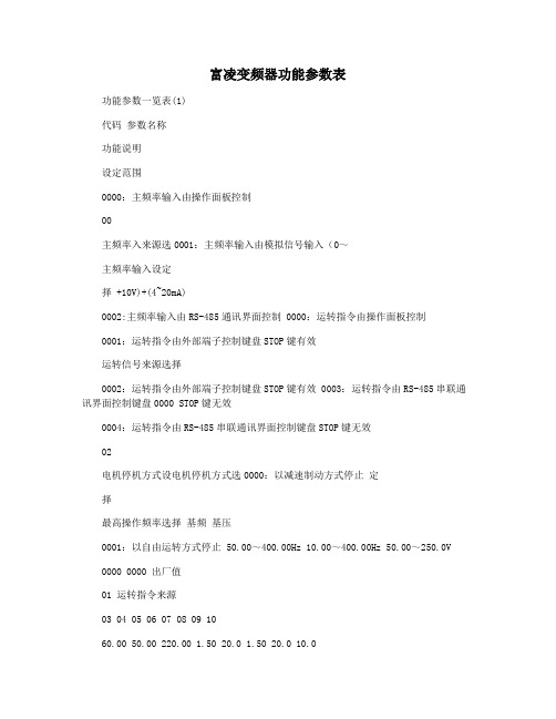
富凌变频器功能参数表功能参数一览表(1)代码参数名称功能说明设定范围0000:主频率输入由操作面板控制00主频率入来源选0001:主频率输入由模拟信号输入(0~主频率输入设定择 +10V)+(4~20mA)0002:主频率输入由RS-485通讯界面控制 0000:运转指令由操作面板控制0001:运转指令由外部端子控制键盘STOP键有效运转信号来源选择0002:运转指令由外部端子控制键盘STOP键有效 0003:运转指令由RS-485串联通讯界面控制键盘0000 STOP键无效0004:运转指令由RS-485串联通讯界面控制键盘STOP键无效02电机停机方式设电机停机方式选0000:以减速制动方式停止定择最高操作频率选择基频基压0001:以自由运转方式停止 50.00~400.00Hz 10.00~400.00Hz 50.00~250.0V0000 0000 出厂值01 运转指令来源03 04 05 06 07 08 09 1060.00 50.00 220.00 1.50 20.0 1.50 20.0 10.0V/F曲线设定中间频率选择 0.01~400.00Hz中间电压选择 2.0~250.0V 最低输出频率选择启动电压第一加速时间选择第一减速速时间选择加减速时间设定第二加速时间选择第二减速速时间选择点动加减速时间点动加减时间选选择 S-曲线设定择S曲线缓加减速选择0.01~20.00Hz 2.0~50.0V 0.1~999.9sec11 0.1~999.9sec 10.012 0.1~999.9sec 10.013 0.1~999.9sec 10.014 0.1~600.0sec 10.015 16 17 18 190~7 0 0.00 0.00 0.00 0.00第一段频率选择 0.00~400.00Hz 第二段频率选择 0.00~400.00Hz多段速运转设定第三段频率选择 0.00~400.00Hz第lh 段频率选择0.00~400.00Hz20第五段频率选择 0.00~400.00Hz 0.00功能参数一览表(2)代码参数名称功能说明设定范围出厂值 21 第六段频率选择 0.00~400.00Hz 22第七段频率选择 0.00~400.00Hz 23 点动频率设定点动频率设定 0.01~400.00Hz 24反转禁止设定反转禁止功能设定 0000: 0001: 25 过电压失速防止过电压失速防止0000: 功能设定功能选择0001: 26 过电流失速防止加速中,过电流检出准位50~200% 27 功能设定转矩中,过电流检出准位 50~200% 28 直流制动电流准位设定 0~100% 29启动时直流制动时间设0.0~5.0sec直流制动功能设定定30 停止时直流制动时间设定0.0~25.0sec 31停止时直流制动制动0.00~60.00Hz0000:瞬间停电后,不继续运转 0001:瞬间停电后,继续运转变频器32瞬间停电运转选择由停电前速度往下追踪瞬间停电再启动0002:瞬间停电后,继续运转变频器由最小起始速度上追踪33 功能设定允许停电之最大时间 0.3~5.0sec 34 复电后追踪之时间 0.3~5.0sec 35 速度追踪之最大电流设定30~200% 36 37输出频率限制设定输出频率上限选择 0.01~400.00Hz 输出频率下限选择0.00~400.00Hz 0000:正转/停止,反转/停止38 外部运转指令选择二线式/三线式 0001:反转/正转,运转/停止运转控制0002:三线式运转控制一 0003:三线式运转控制二39 多功能输入选择一 0000:多段指令一 40 多功能输入选择二 0001:多段指令二 41多功能输入端子多功能输入选择三0002:多段指令三功能设定0003:点动频率指令42多功能输入选择四0004:加减速禁止指令 0005:第一、第二加减速时间切换 0006:外部中断,常开接点(NO)输入0.00 0.00 5.00 00000001 170% 170% 0%00002.0 2.0 150% 200.00 00.000000000 0001 000200130007:外部中断,常闭接点(NC)输入0008:上频率指令(Up)功能参数一览表(3)代码参数名称功能说明设定范围0009:下频率指令(Down)0010:计数器清零 0011:正转点动指令 0012:反转点动指令 0013:外部故障常开接点(NO)输入0014:外部故障常闭接点(NC)输入 0015:外部中断,不再启动(NO)输入 0016:外部中断,不再启动(NC)输入0017:参数锁定 0018:强制运转指令面板给定 0019:强制运转指令面板给定0020:无功能43 44 45数字频率计类比输出增益设定数字输出频率倍数设定类比输出增益设定多功能输出端子一(MO1) 多功能输出端子二(MO2)1~20 1~200% 0000:运转中指示 0001:设定频率到达指示 0002:任意频率到达指示0003:计数到达指示多功能输出端子46设定0004:非零速 0005:过转矩指示 0006:外部中断指示 0007:低电压检出指示 0008:变频器超做操作模式0009:故障指示47任意到达频率设定任意到达频率设定最高频率模拟设定最低频率模拟设定模拟信号输出选择电机额定电流设定电机空载电流设定自动转矩补偿设定自动转矩补偿增益0.00~400.00Hz 0.0~10.0V 0.0~10.0V0000:类比频率计(0到最高操作频率)0001:(0到250%额定电流)30~120% 0~99% 0~ 10% 0.0~10.00.00 10.0 0.3 0000 100% 40% 3% 0.0 0001 1 100% 0000 出厂值48 模拟输入/频率指令 49 50 51 52 53 54 55 56曲线设定模拟输出频率/ 电流信号设定保留电机运转资料设定转矩补偿设定转差补偿设定保留功能参数一览表(4)代码参数名称功能说明设定范围出厂值0000:故障指示 0001:运转中指示多功能输出接点设定多功能输出接点指示常开接点(A-B) 常闭接点(B-C)0002:设定频率到达指示 0003:任意频率到达指示0004:非零速 0005:过转矩指示 0006:外部中断指示 0000:以标准电动机动作 58电子热续电器指示电子热续电器选择0001:以特殊电机动作0002:不动作59电子人继电器动作时间30~300S 0000:过转矩不检测0001:定速运转中过转矩检测,过转矩检出(E013)停止运转 0002:定速运转中过矩检测,过转60过转矩检出功能选择过转矩检出功能选择矩检出后(E013)继续运转 0003:运转中过转矩检测,过转矩检出后(E013)停止运转 0004:运转中过转矩检测,过转矩检出后(E013)继续运转61 62 63 66计数值到达功能设定过转矩检出准位过转矩检出时间选择指定计数值设定计数值到达设定30~200% 0.1~10.0S 1~9999 1~99990000:显示实际运转频率(P) 0001:显示使用者定义输出物理量(n)0002:显示内部计数器(r)64功能显示项目设定输出物理项目设定0003:显示输入电压值(u)0004:保留 0005:保留 0006:保留65 67 68 69 7057 00000002600000150% 0.1 1 10000比例常数设定比例常数设定跳跃频率一0.1~200.0 0.00~400.00Hz 0.00~400.00Hz 0.00~400.00Hz 0.01~20.00Hz1.0 0.00 0.00 0.00 0.01跳跃频率设定跳跃频率二跳跃频率三跳跃频率宽度设定功能参数一览表(5)代码参数名称功能说明设定范围0001:fc=3kHz, 0002:fc=6kHz71PWM频率设定载波频率选择0003:fc=9KHz 0004:fc=12KHz0005:fc=15KHz.72故障后,自动重置/启动次数设定0~10出厂值随规格而设定 073 74故障记录检查7576 77 78 79 80最近第一次故障记录 0000:无故障记录(清除故障记录)最近第二次故障记录 0001:过电流最近第三次故障记录0002:过电压 0003:过热 0004:过负载 0005:过负载1 0006:外部故障 0007:CPU故障1 0008:CPU故障3 0009:控制器保护线路故障 0010:加速中电流值超过额定电流值二倍0011:减速中电流值超过额定电流值二倍 0012:恒速中电流值超过额定电流值二倍0013:接地保护或保险丝熔断0014:保留 0015:保留 0016:保留 0017:外部中断允许 0018:过负载2 0019:保留0020:保留0000:所有的参数值设定为可读/写模式0001:所有的参数设定为仅读模式0002~0009:不使用 0010:所有的参数设定为出厂值 0000:1200 baud (数据传输速率位元/秒)0001:2400 baud (数据传输速率位元/秒) 0002:4800 baud (数据传输速率位元/秒)0000~0030仅可读取0000 0000000000000002 0000 0000 **##感谢您的阅读,祝您生活愉快。
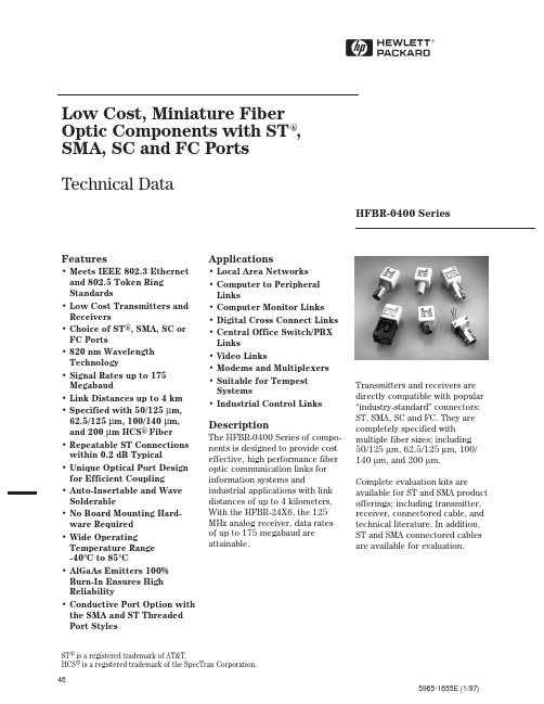
46Transmitters and receivers are directly compatible with popular “industry-standard” connectors: ST, SMA, SC and FC. They are completely specified with multiple fiber sizes; including50/125 µm, 62.5/125 µm, 100/ 140 µm, and 200 µm.Complete evaluation kits are available for ST and SMA product offerings; including transmitter, receiver, connectored cable, and technical literature. In addition, ST and SMA connectored cables are available for evaluation.Low Cost, Miniature FiberOptic Components with ST®,SMA, SC and FC PortsTechnical DataHFBR-0400 SeriesFeatures• Meets IEEE 802.3 Ethernet and 802.5 Token Ring Standards• Low Cost Transmitters and Receivers• Choice of ST®, SMA, SC or FC Ports• 820 nm Wavelength Technology• Signal Rates up to 175 Megabaud• Link Distances up to 4 km • Specified with 50/125 µm, 62.5/125 µm, 100/140 µm, and 200 µm HCS® Fiber• Repeatable ST Connections within 0.2 dB Typical• Unique Optical Port Design for Efficient Coupling• Auto-Insertable and Wave Solderable• No Board Mounting Hard-ware Required• Wide Operating Temperature Range-40°C to 85°C• AlGaAs Emitters 100%Burn-In Ensures High Reliability• Conductive Port Option with the SMA and ST Threaded Port Styles Applications• Local Area Networks• Computer to Peripheral Links• Computer Monitor Links • Digital Cross Connect Links • Central Office Switch/PBX Links• Video Links• Modems and Multiplexers • Suitable for Tempest Systems• Industrial Control Links DescriptionThe HFBR-0400 Series of compo-nents is designed to provide cost effective, high performance fiber optic communication links for information systems and industrial applications with link distances of up to 4 kilometers. With the HFBR-24X6, the 125 MHz analog receiver, data rates of up to 175 megabaud are attainable.ST® is a registered trademark of AT&T. HCS®is a registered trademark of the SpecTran Corporation.5965-1655E (1/97)47HFBR-0400 Series Part Number GuideHFBR X4XXaa1 = Transmitter Option T (Threaded Port Option)2 = ReceiverOption C (Conductive Port Receiver Option)Option M (Metal Port Option)4 = 820 nm Transmitter andOption K (Kinked Lead Option)Receiver Products TA = Square pinout/straight lead TB = Square pinout/bent leads0 = SMA, Housed HA = Diamond pinout/straight leads 1 = ST, Housed HB = Diamond pinout/bent leads 2 = FC, Housed E = SC, Housed2 = Tx, Standard Power3 = SMA Port, 90 deg. Bent Leads4 = Tx, High Power4 = ST Port, 90 deg. Bent Leads 2 = Rx,5 MBd, TTL Output5 = SMA Port, Straight Leads6 = Rx, 125 MHz, Analog Output6 = ST Port, Straight LeadsLINK SELECTION GUIDEData Rate (MBd)Distance (m)Transmitter Receiver Fiber Size (µm)Evaluation Kit 51500HFBR-14X2HFBR-24X2200 HCS N/A52000HFBR-14X4HFBR-24X262.5/125HFBR-04X0202700HFBR-14X4HFBR-24X662.5/125HFBR-0414,HFBR-0463322200HFBR-14X4HFBR-24X662.5/125HFBR-0414551400HFBR-14X4HFBR-24X662.5/125HFBR-0414125700HFBR-14X4HFBR-24X662.5/125HFBR-0416155600HFBR-14X4HFBR-24X662.5/125HFBR-0416175500HFBR-14X4HFBR-24X662.5/125HFBR-0416For additional information on specific links see the following individual link descriptions. Distances measured over temperature range from 0 to 70°C.Applications Support GuideThis section gives the designer information necessary to use the HFBR-0400 series components tomake a functional fiber-optic transceiver. HP offers a wide selection of evaluation kits for hands-on experience with fiber-optic products as well as a wideApplication LiteratureTitleDescriptionHFBR-0400 Series Transmitter & Receiver Reliability DataReliability DataApplication Bulletin 73Low Cost Fiber Optic Transmitter & Receiver Interface Circuits Application Bulletin 78Low Cost Fiber Optic Links for Digital Applications up to 155 MBdApplication Note 1038Complete Fiber Solutions for IEEE 802.3 FOIRL, 10Base-FB and 10 Base-FL Application Note 1065Complete Solutions for IEEE 802.5J Fiber-Optic Token Ring Application Note 1073HFBR-0319 Test Fixture for 1X9 Fiber Optic TransceiversApplication Note 1086Optical Fiber Interconnections in Telecommunication Productsrange of application notes com-plete with circuit diagrams and board layouts. Furthermore, HP’s application support group is always ready to assist with any design consideration.HFBR-0400 Series Evaluation KitsHFBR-0410 ST Evaluation Kit Contains the following :• One HFBR-1412 transmitter • One HFBR-2412 five megabaud TTL receiver• Three meters of ST connec-tored 62.5/125 (µm fiber optic cable with low cost plastic ferrules.• Related literatureHFBR-0414 ST Evaluation Kit Includes additional components to interface to the transmitter and receiver as well as the PCB to reduce design time.Contains the following:• One HFBR-1414T transmitter • One HFBR-2416T receiver• Three meters of ST connec-tored 62.5/125 µm fiber optic cable• Printed circuit board• ML-4622 CP Data Quantizer • 74ACTllOOON LED Driver• LT1016CN8 Comparator• 4.7 µH Inductor• Related literatureHFBR-0400 SMA Evaluation KitContains the following :• One HFBR-1402 transmitter • One HFBR-2402 five megabaud TTL receiver• Two meters of SMA connectored 1000 µm plastic optical fiber• Related literature HFBR-0416 Evaluation KitContains the following:• One fully assembled 1x9transceiver board for 155 MBdevaluation including:-HFBR-1414 transmitter-HFBR-2416 receiver-circuitry• Related literatureHFBR-0463 Ethernet MAUEvaluation KitContains the following:• One fully assembled MediaAttachment Unit (MAU) boardwhich includes:-HFBR-1414 transmitter-HFBR-2416 receiver-HFBR-4663 IC• Related literatureNote: Cable not included. OrderHFBR-BXS010 seperately (2pieces)Package and HandlingInformationPackage InformationAll HFBR-0400 Seriestransmitters and receivers arehoused in a low-cost, dual-inlinepackage that is made of highstrength, heat resistant, chem-ically resistant, and UL 94V-Oflame retardant ULTEM® (plastic(UL File #E121562). Thetransmitters are easily identifiedby the light grey color connectorport. The receivers are easilyidentified by the dark grey colorconnector port. (Black color forconductive port.) The package isdesigned for auto-insertion andwave soldering so it is ideal forhigh volume productionapplications.Handling and DesignInformationEach part comes with a protectiveport cap or plug covering theoptics. These caps/plugs will varyby port style. When soldering, itis advisable to leave the protec-tive cap on the unit to keep theoptics clean. Good systemperformance requires clean portoptics and cable ferrules to avoidobstructing the optical path.Clean compressed air often issufficient to remove particles ofdirt; methanol on a cotton swabalso works well.Recommended Chemicals forCleaning/DegreasingHFBR-0400 ProductsAlcohols: methyl, isopropyl,isobutyl. Aliphatics: hexane,heptane, Other: soap solution,naphtha.Do not use partially halogenatedhydrocarbons such as 1,1.1trichloroethane, ketones such asMEK, acetone, chloroform, ethylacetate, methylene dichloride,phenol, methylene chloride, orN-methylpyrolldone. Also, HPdoes not recommend the use ofcleaners that use halogenatedhydrocarbons because of theirpotential environmental harm.Ultem® is a registered Trademark of the GE corporation.48Mechanical Dimensions HFBR-0400 SMA SeriesHFBR-X45XHFBR-X40XDIAPART MARKINGYYWW8.6(0.34)DIADIA PINCIRCLE3.81(0.15)DIAPINS 2,3,6,70.46(0.018)DIA.INDICATOR4950Mechanical Dimensions HFBR-0400 ST SeriesHFBR-X46XHFBR-X41X8.6(0.34)NOTE 2DIANOTE: ALL DIMENSIONS IN MILLIMETRES AND (INCHES).3.81(0.15)DIA0.46(0.018)INDICATOR51Mechanical Dimensions HFBR-0400T Threaded ST SeriesHFBR-X46XTHFBR-X41XT3.81(0.15)DIAINDICATOR0.46(0.018)NOTE 27.68.6(0.34)Mechanical Dimensions HFBR-0400 FC SeriesMechanical Dimensions HFBR-0400 SC Series3.81(0.15)INDICATORM8 x 0.75 6GTHREAD (METRIC)(0.14)HFBR-X4EX5253Figure 1. HFBR-0400 ST Series Cross-Sectional View.Panel Mount HardwarePort Cap HardwareHFBR-4402: 500 SMA Port CapsHFBR-4120: 500 ST Port Plugs (120 psi)HFBR-4412: 500 FC Port Caps HFBR-4417: 500 SC Port PlugsTYP DIA1.65(0.065)WASHERTYP DIA1.65(0.065)HFBR-4401: for SMA PortsHFBR-4411: for ST Ports(Each HFBR-4401 and HFBR-4411 kit consists of 100 nuts and 100 washers.)OptionsIn addition to the various portstyles available for the HFBR-0400 series products, there are also several extra options that can be ordered. To order an option, simply place the corre-sponding option number at the end of the part number. For instance, a metal-port option SMA receiver would be HFBR-2406M. You can add any number of options in series at the end of a part number. Please contact your local sales office for further information or browse HP’s fiber optics home page at http:// /go/fiberOption T (Threaded Port Option)• Allows ST style port com-ponents to be panel mounted.• Compatible with all current makes of ST multimode connectors• Mechanical dimensions are compliant with MIL-STD-83522/13• Maximum wall thickness when using nuts and washers from the HFBR-4411 hardware kit is 2.8 mm (0.11 inch)• Available on all ST ports Option C (Conductive PortReceiver Option)• Designed to withstand electro-static discharge (ESD) of 25kV to the port• Significantly reduces effect of electromagnetic interference (EMI) on receiver sensitivity • Allows designer to separate thesignal and conductive portgrounds• Recommended for use in noisyenvironments• Available on SMA and threadedST port style receivers onlyOption M (Metal Port Option)• Nickel plated aluminum con-nector receptacle• Designed to withstand electro-static discharge (ESD) of 15kVto the port• Significantly reduces effect ofelectromagnetic interference(EMI) on receiver sensitivity• Allows designer to separate thesignal and metal port grounds• Recommended for use in verynoisy environments• Available on SMA, FC, ST, andthreaded ST portsOption K (Kinked LeadOption)• Grounded outside 4 leads are“kinked”• Allows components to stayanchored in the PCB duringwave solder and aqueous washprocessesOptions TA, TB, HA, HB(Active Device MountOptions)(These options are unrelated tothe threaded port option T.)• All metal, panel mountablepackage with a 3 or 4 pinreceptacle end• Available for HFBR-14X4, 24X2and 24X6 components• Choose from diamond orsquare pinout, straight or bentleads ADM Picture• TA = Square pinout/straightleadsTB = Square pinout/bent leadsHA = Diamond pinout/straightleadsHB = Diamond pinout/bentleadsDuplex OptionIn addition to the standardoptions, some HFBR-0400 seriesproducts come in a duplex con-figuration with the transmitter onthe left and the receiver on theright. This option was designedfor ergonomic and efficientmanufacturing. The followingpart numbers are available in theduplex option:HFBR-5414 (Duplex ST)HFBR-5414T (Duplex ThreadedST)HFBR-54E4 (Duplex SC)54Typical Link Data HFBR-0400 SeriesDescriptionThe following technical data is taken from 4 popular links using the HFBR-0400 series: the 5 MBd link, Ethernet 20 MBd link, Token Ring 32 MBd link, and the 155 MBd link. The data given corresponds to transceiver solu-tions combining the HFBR-0400series components and variousrecommended transceiver designcircuits using off-the-shelfelectrical components. This datais meant to be regarded as anexample of typical link perform-ance for a given design and doesnot call out any link limitations.Please refer to the appropriateapplication note given for eachlink to obtain more information.5 MBd Link (HFBR-14XX/24X2)Link Performance -40°C to +85°C unless otherwise specifiedNotes:1. OPB at T A = -40 to 85°C, V CC = 5.0 V dc, I F ON = 60 mA. P R = -24 dBm peak.2. Synchronous data rate limit is based on these assumptions: a) 50% duty factor modulation, e.g., Manchester I or BiPhaseManchester II; b) continuous data; c) PLL Phase Lock Loop demodulation; d) TTL threshold.3. Asynchronous data rate limit is based on these assumptions: a) NRZ data; b) arbitrary timing-no duty factor restriction; c) TTLthreshold.55565 MBd Logic Link DesignIf resistor R 1 in Figure 2 is 70.4Ω, a forward current I F of 48 mA is applied to the HFBR-14X4 LED transmitter. With I F =48 mA the HFBR-14X4/24X2logic link is guaranteed to work with 62.5/125 µm fiber optic cable over the entire range of 0to 1750 meters at a data rate of dc to 5 MBd, with arbitrary data format and pulse width distortion typically less than 25%. Bysetting R 1 = 115 Ω, the transmit-ter can be driven with I F =30mA,if it is desired to economize on power or achieve lower pulse distortion.The following example will illus-trate the technique for selecting the appropriate value of I F and R 1.Maximum distance required=400 meters. From Figure 3 the drive current should be 15 mA.From the transmitter dataV F =1.5 V (max.) at I F = 15 mA as shown in Figure 9.V CC - V F 5 V - 1.5 V R 1 = ––––––– = –––––––––I F 15 mA R 1 = 233␣ΩThe curves in Figures 3, 4, and 5are constructed assuming no in-line splice or any additional system loss. Should the link consists of any in-line splices,these curves can still be used to calculate link limits provided they are shifted by the additionalsystem loss expressed in dB. For example, Figure 3 indicates that with 48 mA of transmitter drive current, a 1.75 km link distance is achievable with 62.5/125 µm fiber which has a maximum attenuation of 4 dB/km. With 2dB of additional system loss, a 1.25 km link distance is still achievable.Figure 2. Typical Circuit Configuration.57Figure 6. Propagation Delay through System with One Meter of Cable.Figure 8. System Propagation Delay Test Circuit and Waveform Timing Definitions.Figure 3. HFBR-1414/HFBR-2412Link Design Limits with 62.5/125 µm Cable.Figure 4. HFBR-14X2/HFBR-24X2Link Design Limits with 100/140 µm Cable.Figure 7. Typical Distortion of Pseudo Random Data at 5 Mb/s.Figure 5. HFBR-14X4/HFBR-24X2Link Design Limits with 50/125 µmCable.0-1-2-3-4-5-610 L O G (t /t o ) N O R M A L I Z E D T R A N S M I T T E R C U R R E N T (d B )LINK LENGTH (km)I F T R A N S M I T T E R F O R W A R D C U R R E N T (mA )605075-22-21-20-19-18-17-16-15-14-13-12P R – RECEIVER POWER – dBmt P H L O R t P H L P R O P O G A T I O N D E L A Y –n s706560555045403530252055-22-21-20-19-18-17-16-15-14-13-12P R – RECEIVER POWER – dBmt D – N R Z D I S T O R T I O N – n s50454035302520Ethernet 20 MBd Link (HFBR-14X4/24X6)(refer to Application Note 1038 for details)Typical Link PerformanceNotes:1. Typical data at T A = 25°C, V CC = 5.0 V dc.2. Typical performance of circuits shown in Figure 1 and Figure 3 of AN-1065 (see applications support section) 58155 MBd Link (HFBR-14X4/24X6)(refer to Application Bulletin 78 for details)Typical Link PerformanceNotes:1. Typical data at T A = 25°C, V CC = 5.0 V dc, PECL serial interface.2. Typical OPB was determined at a probability of error (BER) of 10-9. Lower probabilities of error can be achieved with short fibersthat have less optical loss.5960HFBR-14X2/14X4 Low-Cost High-Speed TransmittersDescriptionThe HFBR-14XX fiber optic transmitter contains an 820 nm AlGaAs emitter capable of efficiently launching optical power into four different optical fiber sizes: 50/125 µm, 62.5/125µm, 100/140 µm, and 200 µm HCS ®. This allows the designer flexibility in choosing the fiber size. The HFBR-14XX is designed to operate with the Hewlett-Packard HFBR-24XX fiber optic receivers.The HFBR-14XX transmitter’s high coupling efficiency allows the emitter to be driven at low current levels resulting in lowpower consumption and increased reliability of the transmitter. The HFBR-14X4 high power transmit-ter is optimized for small sizefiber and typically can launch -15.8 dBm optical power at60mA into 50/125 µm fiber and -12 dBm into 62.5/125µm fiber.The HFBR-14X2 standardtransmitter typically can launch -12 dBm of optical power at 60mA into 100/140 µm fiber cable. It is ideal for large size fiber such as 100/140 µm. The high launched optical power level is useful for systems where star couplers, taps, or inline connec-tors create large fixed losses.Consistent coupling efficiency is assured by the double-lens optical system (Figure 1). Power coupled into any of the three fiber types varies less than 5 dB from part to part at a given drive current and temperature. Consistent coupling efficiency reduces receiver dynamic range requirements which allows for longer link lengths.Absolute Maximum RatingsHoused ProductUnhoused Product61HFBR-14X2 Output Power Measured Out of 1 Meter of CableElectrical/Optical Specifications -40°C to +85°C unless otherwise specified.CAUTION: The small junction sizes inherent to the design of these components increase the components’susceptibility to damage from electrostatic discharge (ESD). It is advised that normal static precautions be taken in handling and assembly of these components to prevent damage and/or degradation which may be induced by ESD.HFBR-14X4 Output Power Measured out of 1 Meter of Cable14X2/14X4 Dynamic CharacteristicsParameter Symbol Min.Typ.[2]Max.Units Conditions Reference Rise Time, Fall Time t r, t f 4.0 6.5nsec I F = 60 mA Note 7, (10% to 90%)No Pre-bias Figure 12Rise Time, Fall Time t r, t f 3.0nsec I F = 10 to Note 7, (10% to 90%)100 mA Figure 11 Pulse Width Distortion PWD0.5nsec Figure 11 Notes:1. For I FPK > 100 mA, the time duration should not exceed 2 ns.2. Typical data at T A = 25°C.3. Thermal resistance is measured with the transmitter coupled to a connector assembly and mounted on a printed circuit board.4. D is measured at the plane of the fiber face and defines a diameter where the optical power density is within 10 dB of themaximum.5. P T is measured with a large area detector at the end of 1 meter of mode stripped cable, with an ST® precision ceramic ferrule (MIL-STD-83522/13) for HFBR-1412/1414, and with an SMA 905 precision ceramic ferrule for HFBR-1402/1404.6. When changing µW to dBm, the optical power is referenced to 1 mW (1000 µW). Optical Power P (dBm) = 10 log P (µW)/1000µW.7. Pre-bias is recommended if signal rate >10 MBd, see recommended drive circuit in Figure 11.8. Pins 2, 6 and 7 are welded to the anode header connection to minimize the thermal resistance from junction to ambient. To furtherreduce the thermal resistance, the anode trace should be made as large as is consistent with good RF circuit design.9. Fiber NA is measured at the end of 2 meters of mode stripped fiber, using the far-field pattern. NA is defined as the sine of the halfangle,determined at 5% of the peak intensity point. When using other manufacturer’s fiber cable, results will vary due to differing NA values and specification methods.All HFBR-14XX LED transmitters are classified as IEC 825-1 Accessible Emission Limit (AEL) Class 1 based upon the current proposed draft scheduled to go in to effect on January 1, 1997. AEL Class 1 LED devices are considered eye safe. Contact your Hewlett-Packard sales representative for more information.CAUTION: The small junction sizes inherent to the design of these components increase the components’susceptibility to damage from electrostatic discharge (ESD). It is advised that normal static precautions be taken in handling and assembly of these components to prevent damage and/or degradation which may be induced by ESD.6263Recommended Drive CircuitsThe circuit used to supply current to the LED transmitter cansignificantly influence the optical switching characteristics of the LED. The optical rise/fall times and propagation delays can be improved by using the appro-priate circuit techniques. The LED drive circuit shown inFigure 11 uses frequency com-pensation to reduce the typical rise/fall times of the LED and a small pre-bias voltage to minimize propagation delay differences that cause pulse-width distortion.The circuit will typically produce rise/fall times of 3 ns, and a total jitter including pulse-width dis-tortion of less than 1 ns. This circuit is recommended for appli-cations requiring low edge jitteror high-speed data transmission at signal rates of up to 155 ponent values for this circuit can be calculated for different LED drive currents using the equations shown below. For additional details about LED drive circuits, the reader is encouraged to read Hewlett-Packard Application Bulletin 78and Application Note 1038.()()(V CC - V F ) + 3.97 (V CC - V F - 1.6 V)(5 - 1.84) + 3.97 (5 - 1.84 - 1.6)R y = –––––––––––––––––––––––––––––––R y = –––––––––––––––––––––––––––––I F ON (A)0.100 1 R y 3.16 + 6.19R X1 = – ––––R y = ––––––––––– = 93.5 Ω2 3.970.1001 93.5R EQ2(Ω) = R X1 - 1R X1 = – ––––= 11.8 Ω2 3.97R X2 = R X3 = R X4 = 3(R EQ2)R EQ2 = 11.8 - 1 = 10.8 Ω2000(ps)C(pF) = ––––––––R X2 = R X3 = R X4 = 3(10.8) = 32.4 Ω R X1(Ω)2000 psExample for I F ON = 100 mA: V F can be C = ––––––– = 169 pF11.8 Ωobtained from Figure 9 (= 1.84 V ).64Figure 9. Forward Voltage and Current Characteristics.Figure 12. Test Circuit for Measuring t r , t f .Figure 11. Recommended Drive Circuit.Figure 10. Normalized TransmitterOutput vs. Forward Current.P (I F ) – P (60 m A ) – R E L A T I V E P O W E R R A T I O02.00.80I F – FORWARD CURRENT – mA2040801.60.41.2601001.81.41.00.60.230507090P (I F ) – P (60 m A ) – R E L A T I V E P O W E R R A T I O – d B-7.0-5.0-4.0-3.0-2.0-1.000.81.01.42.03.065HFBR-24X2 Low-Cost 5MBd Receiver DescriptionThe HFBR-24X2 fiber optic receiver is designed to operate with the Hewlett-Packard HFBR-14XX fiber optic transmitter and 50/125 µm, 62.5/125 µm, 100/140 µm, and 200 µm HCS ® fiber optic cable. Consistent coupling into the receiver is assured by the lensed optical system (Figure 1).Response does not vary with fiber size ≤0.100 µm.The HFBR-24X2 receiver incor-porates an integrated photo IC containing a photodetector and dc amplifier driving an open-collector Schottky output transistor. The HFBR-24X2 isHoused ProductUnhoused Productdesigned for direct interfacing to popular logic families. The absence of an internal pull-up resistor allows the open-collector output to be used with logicfamilies such as CMOS requiring voltage excursions much higher than V CC .Both the open-collector “Data”output Pin 6 and V CC Pin 2 are referenced to “Com” Pin 3, 7. The “Data” output allows busing,strobing and wired “OR” circuit configurations. The transmitter is designed to operate from a single +5 V supply . It is essential that a bypass capacitor (0.1 µF ceramic) be connected from Pin 2 (V CC ) to Pin 3 (circuit common) of the receiver.Absolute Maximum RatingsPIN FUNCTION 1234V CC (5 V)COMMON DATA COMMONElectrical/Optical Characteristics -40°C to + 85°C unless otherwise specifiedFiber sizes with core diameter ≤100 µm and NA ≤0.35, 4.75 V ≤V CC≤5.25 VParameter Symbol Min.Typ.[3]Max.Units Conditions Reference High Level Output Current I OH5250µA V O = 18P R < -40 dBmLow Level Output Voltage V OL0.40.5V I O = 8 mAP R > -24 dBmHigh Level Supply Current I CCH 3.5 6.3mA V CC = 5.25 VP R < -40 dBmLow Level Supply Current I CCL 6.210mA V CC = 5.25 VP R > -24 dBmEquivalent N.A.NA0.50Optical Port Diameter D400µm Note 4 Dynamic Characteristics-40°C to +85°C unless otherwise specified; 4.75 V ≤V CC≤5.25 V; BER ≤10-9Notes:1. 2.0 mm from where leads enter case.2. 8 mA load (5 x 1.6 mA), R L = 560 Ω.3. Typical data at T A = 25°C, V CC = 5.0 Vdc.4. D is the effective diameter of the detector image on the plane of the fiber face. The numerical value is the product of the actualdetector diameter and the lens magnification.5. Measured at the end of 100/140 µm fiber optic cable with large area detector.6. Propagation delay through the system is the result of several sequentially-occurring phenomena. Consequently it is a combinationof data-rate-limiting effects and of transmission-time effects. Because of this, the data-rate limit of the system must be described in terms of time differentials between delays imposed on falling and rising edges.7. As the cable length is increased, the propagation delays increase at 5 ns per meter of length. Data rate, as limited by pulse widthdistortion, is not affected by increasing cable length if the optical power level at the receiver is maintained.CAUTION: The small junction sizes inherent to the design of these components increase the components’HFBR-24X6 Low-Cost 125 MHz Receiver DescriptionThe HFBR-24X6 fiber optic receiver is designed to operate with the Hewlett-Packard HFBR-14XX fiber optic transmitters and 50/125 µm, 62.5/125 µm, 100/ 140 µm and 200 µm HCS® fiber optic cable. Consistent coupling into the receiver is assured by the lensed optical system (Figure 1). Response does not vary with fiber size for core diameters of 100 µm or less.The receiver output is an analog signal which allows follow-on circuitry to be optimized for a variety of distance/data rate requirements. Low-cost external components can be used to convert the analog output to logic compatible signal levels for various data formats and data rates up to 175 MBd. This distance/data rate tradeoff results in increased optical power budget at lower data rates which can be used for additional distance or splices.The HFBR-24X6 receiver contains a PIN photodiode and low noise transimpedance pre-amplifier integrated circuit. The HFBR-24X6 receives an optical signal and converts it to an analog voltage. The output is a buffered emitter-follower. Because the signal amplitude from the HFBR-24X6 receiver is much larger than from a simple PIN photodiode, it is less susceptible to EMI, especially at high signaling rates. For very noisy environments, the conductive or metal port option is recommended.A receiver dynamic range of 23 dB over temperature is achievable (assuming 10-9 BER).The frequency response is typically dc to 125 MHz. Although the HFBR-24X6 is an analog receiver, it is compatible with digital systems. Please refer to Application Bulletin 78 for simple and inexpensive circuits that operate at 155 MBd or higher. The recommended ac coupled receiver circuit is shown in Figure 12. It is essential that a 10 ohm resistor be connected between pin 6 and the power supply, and a 0.1µF ceramic bypass capacitor be connected between the power supply and ground. In addition, pin 6 should be filtered to protect theFigure 11. Simplified Schematic Diagram.Housed ProductUnhoused Productreceiver from noisy host systems. Refer to AN 1038, 1065, or AB 78 for details.PINFUNCTION12*34*SIGNALV EEV CCV EEINDICATORCCEE* PINS 3 AND 7 ARE ELECTRICALLYCONNECTED TO THE HEADER.† PINS 1, 4, 5, AND 8 ARE ISOLATED FROMTHE INTERNAL CIRCUITRY, BUT AREELECTRICALLY CONNECTED TO EACH OTHER.POSITIVE SUPPLY ANALOG SIGNALNEGATIVE SUPPLY。

Fiber-Optic Transmitter and ReceiverReliability Data IntroductionAgilent Technologies’ quality system includes an ongoing reliability monitor program to generate a data base from which this reliability data sheet is published.Transmitter Reliability The HFBR-0400 Series fiberoptic transmitters incorporate AlGaAs emitters and double lens optical systems. This design allows the HFBR-14XX transmitters to be driven at a relatively low current level for a specified amount of coupled power into the fiber. Because transmitter forward currents are proportional to failure rates, a low current translates into excellent transmitter reliability. To further improve reliability, Agilent has implemented a proprietary wafer screening technology that identifies dislocations whichcan lead to the formation of darkline defects (the primary mechanism for transmitter light output failures).HFBR-0400 SeriesTransmitters:HFBR-1402, -1412, -1404, -1414Receivers:HFBR-2402, -2412, -2406, -2416 Transmtter reliability data hasbeen calculated using 100 mAforward current and a 100% dutyfactor. In many actual useconditions, a 50% duty factor andlower forward currents are highlyprobable. When this is true,transmitter reliability will besubstantially better. The degree ofimprovement can be projected byexamining the footnotes below theHFBR-14XX data.Reliability PredictionModelThe reliability prediction modelused to project failure rate andmean time to failure (MTTF) atvarious temperatures shown in thesecond table assumes anexponential cumulative failurefunction (constant failure rate).The Arrhenius temperaturederating equation is used. AgilentTechnologies assumes no failuremechanism change between stressand use conditions. A conservativeactivation energy of 0.43 eV wasused and is derived from MIL-HDBD-217 for hybrid devices.Confidence intervals are basedupon the chi-squaredprediction method associated withexponential distributions.Fiber-Optic TransmitterReliability Data HFBR-1402HFBR-1412HFBR-1404HFBR-1414High Temperature Operating Life TestA. Demonstrated PerformanceTest Equivalent Test Condition Samples Device Hours Failures HTOL T A = 85°C, I F = 100 mA880 units879,5003B. Failure CriteriaFailure has occurred when the unitfails catastrophically, or when thelight output power decreases 3 dB.Point Typical PerformancePerformance [1]in Time [2]in Time(90% Confidence) Ambient Junction MTTF [1]FITs [3]MTTF [2]FITs [3] Temperature (°C)Temperature (°C)(hours)(/109 Hours)(hours)(/109 Hours) 85100293,0003411131,00075968095352,0002844158,00063347590424,0002360190,00052557085514,0001947231,00043376580626,0001598281,00035606075766,0001305344,00029055570945,0001059424,000235750651,172,000854526,000190145601,462,000684657,000152340551,838,000544825,000121235502,326,0004301,044,00095830452,965,0003371,331,00075125403,810,0002631,711,000585C. Failure Rate Prediction for Random Failures (I F @ 100 mA, 100% duty cycle)Notes:1. The point MTTF (representing an esti-mate of the mean point MTTF) is the total device hours divided by either the number performance that is expected from 90% ofall samples. This confidence interval isbased on the statistics of the distribution offailure rates prior to the onset of wear out.Refer to MIL-STD-690 for details of thismethodology.Fiber-Optic Link ReceiverReliability DataHFBR-2402HFBR-2412High Temperature Operating Life TestA. Demonstrated PerformanceTest Equivalent Test Condition Samples Device Hours Failures HTOL T A = 85°C, V CC = 5.25 V3,9602,370,0001B. Failure CriteriaFailure has occurred when the unitfails catastrophically. One devicefailed to switch logic states.Point Typical PerformancePerformance [1]in Time [2]in Time(90% Confidence) Ambient Junction MTTF [1]FITs [3]MTTF [2]FITs [3] Temperature (°C)Temperature (°C)(hours)(/109 Hours)(hours)(/109 Hours) 851002,370,000421609,0001,64080952,880,000346742,0001,34075903,530,000282909,0001,09070854,350,0002291,120,00089265805,400,0001841,390,00071960756,740,0001481,730,00057655708,480,0001172,180,000458506510,700,000932,750,000362456013,600,000733,510,000284405517,500,000564,520,000221355022,700,000435,850,000170304529,700,000337,650,000130254039,200,0002510,000,00099C. Failure Rate Prediction, Receiver (V CC = 5.25 V)Notes:1. The point MTTF (representing an esti-mate of the mean point MTTF) is the total device hours divided by either the number performance that is expected from 90% ofall samples. This confidence interval isuseful life failures. Refer to MIL-STD-690 fordetails of this methodology.Fiber-Optic Link ReceiverReliability DataHFBR-2406HFBR-2416High Temperature Operating Life TestA. Demonstrated PerformanceTest Equivalent Test Condition Samples Device Hours Failures HTOL T A = 85°C, V CC = 5.25 V2,2502,250,0000B. Failure CriteriaFailure has occurred when the unitfails catastrophically.Point Typical PerformancePerformance [1]in Time [2]in Time(90% Confidence) Ambient Junction MTTF [1]FITs [3]MTTF [2]FITs [3] Temperature (°C)Temperature (°C)(hours)(/109 Hours)(hours)(/109 Hours) 851002,250,000444977,164102380952,698,5163711,171,95385375903,252,6873071,412,62770870853,941,1732541,711,63358465804,801,4322082,085,24048060755,882,7441702,554,84939155707,250,3821383,148,80831850658,991,4071113,904,927256456011,222,799894,874,010205405514,102,949716,124,846163355017,848,023567,751,315129304522,755,516449,882,616101254029,238,4093412,698,10779C. Failure Rate Prediction, Receiver (V CC = 5.25 V)Notes:1. The point MTTF (representing an esti-mate of the mean point MTTF) is the total device hours divided by either the number performance that is expected from 90% ofall samples. This confidence interval isuseful life failures. Refer to MIL-STD-690 fordetails of this methodology.HFBR-0400 Mechanical and Environmental Test Data [1]MIL-STD-883D Units Total Test Name Reference Test Conditions Tested Failed Temperature Cycle1010500 cycles from -55 to +125°C, 15 minutes20201at extremes, 5 minutes transfer. [1]HFBR-1414500 cycles from -55 to +125°C, 15 minutes20900at extremes, 5 minutes transfer.[1]HFBR-2416 85/85T A = 85°C, 85% relative humidity,21407No bias, duration = 1,000 hours. [1]HFBR-1414T A = 85°C, 85% relative humidity,22206V CC = 5 volts, Duration = 1,000 hours[1]HFBR-2416 High Temperature1008T A = 125°C800 Storage Condition B1000 hoursResistance to2015Three 1 minute immersions.200 Solvents Brush after solvent immersion.Chemical Resistance— 5 minutes in Acetone, Methanol, Freon TF200and Boiling WaterVibration Variable 2007,20 G min., 20 to 2000 Hz.200 Frequency Condition B4, 4 minute cycles each X, Y, and Z.Thermal Shock1011-55°C to +125°C, 15 cycles600Condition B 5 min. dwell / 10 sec. transferMechanical Shock2002, 5 blows each X1, X2, Y1, Y2, Z1, Z2600Condition B1500 G, 0.5 msec. pulse.Port Wear Test [2]T A = 25°C500 connectorings200Less than 1 dBm variationConnector Side T A = 25°C 1 kg side load100 Load [3]Less than 1 dBm variationPort Strength [4]T A = 25°C 6 kg-cm (5.21 inch-lbs), no port damage100 Seal-Dye Penetrant101445 psi, 10 hours200 (Zyglo)Condition D No Leakage into microelectronic cavitySolderability2003245°C300 ESD Method 3015Human body model @ 10,000 V50HFBR-1414Human body model @ 2,000 V50HFBR-2402Human body model @ 1000 V50HFBR-2416Notes: See following page.Notes:1. Devices were preconditioned with 10 second, 260°C solder dip and 20 cycles, -40°C to 85°C, temperature cycle.2. Coupled power measurements were maximized before and after stress in determining the 1 dBm variation for SMA HFBR-0400 products. HFBR-0400 ST products do not require this due to the improved coupling design.3. The Connector Side Load test was only applied to HFBR-0400 SMA products. The Connector Side Load testing required that the housing be held so to prevent the leads from yielding. The load was applied through a SMA connectored fiber optic cable, perpendicular to the port. The product family is designed to limit cable and ferrule damage due to cable loading. The support and active leads should yield before damage to the cable or connector occurs. If extreme mechanical abuse of the cable/ connector is anticipated please contact Agilent’s Application Department for suggestions about mechanical strain relief. Due to the spring loaded feature of the ST connector, HFBR-0400 ST products will experience 1 dBm coupled power variation at a side load of less than 1 kg.4. The Port Strength test was designed to gauge the concerns with hand tightening the connector to the fiber optic port. The limit is set to alevel beyond most reasonable hand fastening loading.5. Package tests are defined as stresses that indicate the environmental strength of the package. Units tested indicate the total number of devices taken from the product family. While not all part numbers have been subjected to each stress, worst case products have been included.。
Fiber-Optic Transmitter and ReceiverReliability Data IntroductionAgilent Technologies’ quality system includes an ongoing reliability monitor program to generate a data base from which this reliability data sheet is published.Transmitter Reliability The HFBR-0400 Series fiberoptic transmitters incorporate AlGaAs emitters and double lens optical systems. This design allows the HFBR-14XX transmitters to be driven at a relatively low current level for a specified amount of coupled power into the fiber. Because transmitter forward currents are proportional to failure rates, a low current translates into excellent transmitter reliability. To further improve reliability, Agilent has implemented a proprietary wafer screening technology that identifies dislocations whichcan lead to the formation of darkline defects (the primary mechanism for transmitter light output failures).HFBR-0400 SeriesTransmitters:HFBR-1402, -1412, -1404, -1414Receivers:HFBR-2402, -2412, -2406, -2416 Transmtter reliability data hasbeen calculated using 100 mAforward current and a 100% dutyfactor. In many actual useconditions, a 50% duty factor andlower forward currents are highlyprobable. When this is true,transmitter reliability will besubstantially better. The degree ofimprovement can be projected byexamining the footnotes below theHFBR-14XX data.Reliability PredictionModelThe reliability prediction modelused to project failure rate andmean time to failure (MTTF) atvarious temperatures shown in thesecond table assumes anexponential cumulative failurefunction (constant failure rate).The Arrhenius temperaturederating equation is used. AgilentTechnologies assumes no failuremechanism change between stressand use conditions. A conservativeactivation energy of 0.43 eV wasused and is derived from MIL-HDBD-217 for hybrid devices.Confidence intervals are basedupon the chi-squaredprediction method associated withexponential distributions.Fiber-Optic TransmitterReliability Data HFBR-1402HFBR-1412HFBR-1404HFBR-1414High Temperature Operating Life TestA. Demonstrated PerformanceTest Equivalent Test Condition Samples Device Hours Failures HTOL T A = 85°C, I F = 100 mA880 units879,5003B. Failure CriteriaFailure has occurred when the unitfails catastrophically, or when thelight output power decreases 3 dB.Point Typical PerformancePerformance [1]in Time [2]in Time(90% Confidence) Ambient Junction MTTF [1]FITs [3]MTTF [2]FITs [3] Temperature (°C)Temperature (°C)(hours)(/109 Hours)(hours)(/109 Hours) 85100293,0003411131,00075968095352,0002844158,00063347590424,0002360190,00052557085514,0001947231,00043376580626,0001598281,00035606075766,0001305344,00029055570945,0001059424,000235750651,172,000854526,000190145601,462,000684657,000152340551,838,000544825,000121235502,326,0004301,044,00095830452,965,0003371,331,00075125403,810,0002631,711,000585C. Failure Rate Prediction for Random Failures (I F @ 100 mA, 100% duty cycle)Notes:1. The point MTTF (representing an esti-mate of the mean point MTTF) is the total device hours divided by either the number performance that is expected from 90% ofall samples. This confidence interval isbased on the statistics of the distribution offailure rates prior to the onset of wear out.Refer to MIL-STD-690 for details of thismethodology.Fiber-Optic Link ReceiverReliability DataHFBR-2402HFBR-2412High Temperature Operating Life TestA. Demonstrated PerformanceTest Equivalent Test Condition Samples Device Hours Failures HTOL T A = 85°C, V CC = 5.25 V3,9602,370,0001B. Failure CriteriaFailure has occurred when the unitfails catastrophically. One devicefailed to switch logic states.Point Typical PerformancePerformance [1]in Time [2]in Time(90% Confidence) Ambient Junction MTTF [1]FITs [3]MTTF [2]FITs [3] Temperature (°C)Temperature (°C)(hours)(/109 Hours)(hours)(/109 Hours) 851002,370,000421609,0001,64080952,880,000346742,0001,34075903,530,000282909,0001,09070854,350,0002291,120,00089265805,400,0001841,390,00071960756,740,0001481,730,00057655708,480,0001172,180,000458506510,700,000932,750,000362456013,600,000733,510,000284405517,500,000564,520,000221355022,700,000435,850,000170304529,700,000337,650,000130254039,200,0002510,000,00099C. Failure Rate Prediction, Receiver (V CC = 5.25 V)Notes:1. The point MTTF (representing an esti-mate of the mean point MTTF) is the total device hours divided by either the number performance that is expected from 90% ofall samples. This confidence interval isuseful life failures. Refer to MIL-STD-690 fordetails of this methodology.Fiber-Optic Link ReceiverReliability DataHFBR-2406HFBR-2416High Temperature Operating Life TestA. Demonstrated PerformanceTest Equivalent Test Condition Samples Device Hours Failures HTOL T A = 85°C, V CC = 5.25 V2,2502,250,0000B. Failure CriteriaFailure has occurred when the unitfails catastrophically.Point Typical PerformancePerformance [1]in Time [2]in Time(90% Confidence) Ambient Junction MTTF [1]FITs [3]MTTF [2]FITs [3] Temperature (°C)Temperature (°C)(hours)(/109 Hours)(hours)(/109 Hours) 851002,250,000444977,164102380952,698,5163711,171,95385375903,252,6873071,412,62770870853,941,1732541,711,63358465804,801,4322082,085,24048060755,882,7441702,554,84939155707,250,3821383,148,80831850658,991,4071113,904,927256456011,222,799894,874,010205405514,102,949716,124,846163355017,848,023567,751,315129304522,755,516449,882,616101254029,238,4093412,698,10779C. Failure Rate Prediction, Receiver (V CC = 5.25 V)Notes:1. The point MTTF (representing an esti-mate of the mean point MTTF) is the total device hours divided by either the number performance that is expected from 90% ofall samples. This confidence interval isuseful life failures. Refer to MIL-STD-690 fordetails of this methodology.HFBR-0400 Mechanical and Environmental Test Data [1]MIL-STD-883D Units Total Test Name Reference Test Conditions Tested Failed Temperature Cycle1010500 cycles from -55 to +125°C, 15 minutes20201at extremes, 5 minutes transfer. [1]HFBR-1414500 cycles from -55 to +125°C, 15 minutes20900at extremes, 5 minutes transfer.[1]HFBR-2416 85/85T A = 85°C, 85% relative humidity,21407No bias, duration = 1,000 hours. [1]HFBR-1414T A = 85°C, 85% relative humidity,22206V CC = 5 volts, Duration = 1,000 hours[1]HFBR-2416 High Temperature1008T A = 125°C800 Storage Condition B1000 hoursResistance to2015Three 1 minute immersions.200 Solvents Brush after solvent immersion.Chemical Resistance— 5 minutes in Acetone, Methanol, Freon TF200and Boiling WaterVibration Variable 2007,20 G min., 20 to 2000 Hz.200 Frequency Condition B4, 4 minute cycles each X, Y, and Z.Thermal Shock1011-55°C to +125°C, 15 cycles600Condition B 5 min. dwell / 10 sec. transferMechanical Shock2002, 5 blows each X1, X2, Y1, Y2, Z1, Z2600Condition B1500 G, 0.5 msec. pulse.Port Wear Test [2]T A = 25°C500 connectorings200Less than 1 dBm variationConnector Side T A = 25°C 1 kg side load100 Load [3]Less than 1 dBm variationPort Strength [4]T A = 25°C 6 kg-cm (5.21 inch-lbs), no port damage100 Seal-Dye Penetrant101445 psi, 10 hours200 (Zyglo)Condition D No Leakage into microelectronic cavitySolderability2003245°C300 ESD Method 3015Human body model @ 10,000 V50HFBR-1414Human body model @ 2,000 V50HFBR-2402Human body model @ 1000 V50HFBR-2416Notes: See following page.Notes:1. Devices were preconditioned with 10 second, 260°C solder dip and 20 cycles, -40°C to 85°C, temperature cycle.2. Coupled power measurements were maximized before and after stress in determining the 1 dBm variation for SMA HFBR-0400 products. HFBR-0400 ST products do not require this due to the improved coupling design.3. The Connector Side Load test was only applied to HFBR-0400 SMA products. The Connector Side Load testing required that the housing be held so to prevent the leads from yielding. The load was applied through a SMA connectored fiber optic cable, perpendicular to the port. The product family is designed to limit cable and ferrule damage due to cable loading. The support and active leads should yield before damage to the cable or connector occurs. If extreme mechanical abuse of the cable/ connector is anticipated please contact Agilent’s Application Department for suggestions about mechanical strain relief. Due to the spring loaded feature of the ST connector, HFBR-0400 ST products will experience 1 dBm coupled power variation at a side load of less than 1 kg.4. The Port Strength test was designed to gauge the concerns with hand tightening the connector to the fiber optic port. The limit is set to alevel beyond most reasonable hand fastening loading.5. Package tests are defined as stresses that indicate the environmental strength of the package. Units tested indicate the total number of devices taken from the product family. While not all part numbers have been subjected to each stress, worst case products have been included.。


ns1402材料标准
NS1402是一种钛稳定化处理的全奥氏体镍铁铬合金,也被称为NS142或NS1402。
它是一种通用的工程合金,在氧化和还原环境下都具有抗酸和碱金属腐蚀性能。
NS1402应用于各种使用温度不超过550℃的工业领域。
关于NS1402材料的执行标准,一种说法称其执行标准为GB/T。
另外,其化学成分包括碳、锰、镍、硅、磷、硫、铬、铁、铝、钛、铜和钼等元素,其中各元素的含量范围如下:
碳(C)≤
锰(Mn)≤
镍(Ni)~
硅(Si)≤
磷(P)≤
硫(S)≤
铬(Cr)~
铁(Fe) ≥
铝(Al) ≤
钛(Ti) ~
铜(Cu) ~
钼(Mo)~
如需获取更多关于NS1402材料标准的信息,建议查阅相关的专业金属材料书籍或咨询材料科学专家。
Fiber-Optic Transmitter and ReceiverReliability Data IntroductionAgilent Technologies’ quality system includes an ongoing reliability monitor program to generate a data base from which this reliability data sheet is published.Transmitter Reliability The HFBR-0400 Series fiberoptic transmitters incorporate AlGaAs emitters and double lens optical systems. This design allows the HFBR-14XX transmitters to be driven at a relatively low current level for a specified amount of coupled power into the fiber. Because transmitter forward currents are proportional to failure rates, a low current translates into excellent transmitter reliability. To further improve reliability, Agilent has implemented a proprietary wafer screening technology that identifies dislocations whichcan lead to the formation of darkline defects (the primary mechanism for transmitter light output failures).HFBR-0400 SeriesTransmitters:HFBR-1402, -1412, -1404, -1414Receivers:HFBR-2402, -2412, -2406, -2416 Transmtter reliability data hasbeen calculated using 100 mAforward current and a 100% dutyfactor. In many actual useconditions, a 50% duty factor andlower forward currents are highlyprobable. When this is true,transmitter reliability will besubstantially better. The degree ofimprovement can be projected byexamining the footnotes below theHFBR-14XX data.Reliability PredictionModelThe reliability prediction modelused to project failure rate andmean time to failure (MTTF) atvarious temperatures shown in thesecond table assumes anexponential cumulative failurefunction (constant failure rate).The Arrhenius temperaturederating equation is used. AgilentTechnologies assumes no failuremechanism change between stressand use conditions. A conservativeactivation energy of 0.43 eV wasused and is derived from MIL-HDBD-217 for hybrid devices.Confidence intervals are basedupon the chi-squaredprediction method associated withexponential distributions.Fiber-Optic TransmitterReliability Data HFBR-1402HFBR-1412HFBR-1404HFBR-1414High Temperature Operating Life TestA. Demonstrated PerformanceTest Equivalent Test Condition Samples Device Hours Failures HTOL T A = 85°C, I F = 100 mA880 units879,5003B. Failure CriteriaFailure has occurred when the unitfails catastrophically, or when thelight output power decreases 3 dB.Point Typical PerformancePerformance [1]in Time [2]in Time(90% Confidence) Ambient Junction MTTF [1]FITs [3]MTTF [2]FITs [3] Temperature (°C)Temperature (°C)(hours)(/109 Hours)(hours)(/109 Hours) 85100293,0003411131,00075968095352,0002844158,00063347590424,0002360190,00052557085514,0001947231,00043376580626,0001598281,00035606075766,0001305344,00029055570945,0001059424,000235750651,172,000854526,000190145601,462,000684657,000152340551,838,000544825,000121235502,326,0004301,044,00095830452,965,0003371,331,00075125403,810,0002631,711,000585C. Failure Rate Prediction for Random Failures (I F @ 100 mA, 100% duty cycle)Notes:1. The point MTTF (representing an esti-mate of the mean point MTTF) is the total device hours divided by either the number performance that is expected from 90% ofall samples. This confidence interval isbased on the statistics of the distribution offailure rates prior to the onset of wear out.Refer to MIL-STD-690 for details of thismethodology.Fiber-Optic Link ReceiverReliability DataHFBR-2402HFBR-2412High Temperature Operating Life TestA. Demonstrated PerformanceTest Equivalent Test Condition Samples Device Hours Failures HTOL T A = 85°C, V CC = 5.25 V3,9602,370,0001B. Failure CriteriaFailure has occurred when the unitfails catastrophically. One devicefailed to switch logic states.Point Typical PerformancePerformance [1]in Time [2]in Time(90% Confidence) Ambient Junction MTTF [1]FITs [3]MTTF [2]FITs [3] Temperature (°C)Temperature (°C)(hours)(/109 Hours)(hours)(/109 Hours) 851002,370,000421609,0001,64080952,880,000346742,0001,34075903,530,000282909,0001,09070854,350,0002291,120,00089265805,400,0001841,390,00071960756,740,0001481,730,00057655708,480,0001172,180,000458506510,700,000932,750,000362456013,600,000733,510,000284405517,500,000564,520,000221355022,700,000435,850,000170304529,700,000337,650,000130254039,200,0002510,000,00099C. Failure Rate Prediction, Receiver (V CC = 5.25 V)Notes:1. The point MTTF (representing an esti-mate of the mean point MTTF) is the total device hours divided by either the number performance that is expected from 90% ofall samples. This confidence interval isuseful life failures. Refer to MIL-STD-690 fordetails of this methodology.Fiber-Optic Link ReceiverReliability DataHFBR-2406HFBR-2416High Temperature Operating Life TestA. Demonstrated PerformanceTest Equivalent Test Condition Samples Device Hours Failures HTOL T A = 85°C, V CC = 5.25 V2,2502,250,0000B. Failure CriteriaFailure has occurred when the unitfails catastrophically.Point Typical PerformancePerformance [1]in Time [2]in Time(90% Confidence) Ambient Junction MTTF [1]FITs [3]MTTF [2]FITs [3] Temperature (°C)Temperature (°C)(hours)(/109 Hours)(hours)(/109 Hours) 851002,250,000444977,164102380952,698,5163711,171,95385375903,252,6873071,412,62770870853,941,1732541,711,63358465804,801,4322082,085,24048060755,882,7441702,554,84939155707,250,3821383,148,80831850658,991,4071113,904,927256456011,222,799894,874,010205405514,102,949716,124,846163355017,848,023567,751,315129304522,755,516449,882,616101254029,238,4093412,698,10779C. Failure Rate Prediction, Receiver (V CC = 5.25 V)Notes:1. The point MTTF (representing an esti-mate of the mean point MTTF) is the total device hours divided by either the number performance that is expected from 90% ofall samples. This confidence interval isuseful life failures. Refer to MIL-STD-690 fordetails of this methodology.HFBR-0400 Mechanical and Environmental Test Data [1]MIL-STD-883D Units Total Test Name Reference Test Conditions Tested Failed Temperature Cycle1010500 cycles from -55 to +125°C, 15 minutes20201at extremes, 5 minutes transfer. [1]HFBR-1414500 cycles from -55 to +125°C, 15 minutes20900at extremes, 5 minutes transfer.[1]HFBR-2416 85/85T A = 85°C, 85% relative humidity,21407No bias, duration = 1,000 hours. [1]HFBR-1414T A = 85°C, 85% relative humidity,22206V CC = 5 volts, Duration = 1,000 hours[1]HFBR-2416 High Temperature1008T A = 125°C800 Storage Condition B1000 hoursResistance to2015Three 1 minute immersions.200 Solvents Brush after solvent immersion.Chemical Resistance— 5 minutes in Acetone, Methanol, Freon TF200and Boiling WaterVibration Variable 2007,20 G min., 20 to 2000 Hz.200 Frequency Condition B4, 4 minute cycles each X, Y, and Z.Thermal Shock1011-55°C to +125°C, 15 cycles600Condition B 5 min. dwell / 10 sec. transferMechanical Shock2002, 5 blows each X1, X2, Y1, Y2, Z1, Z2600Condition B1500 G, 0.5 msec. pulse.Port Wear Test [2]T A = 25°C500 connectorings200Less than 1 dBm variationConnector Side T A = 25°C 1 kg side load100 Load [3]Less than 1 dBm variationPort Strength [4]T A = 25°C 6 kg-cm (5.21 inch-lbs), no port damage100 Seal-Dye Penetrant101445 psi, 10 hours200 (Zyglo)Condition D No Leakage into microelectronic cavitySolderability2003245°C300 ESD Method 3015Human body model @ 10,000 V50HFBR-1414Human body model @ 2,000 V50HFBR-2402Human body model @ 1000 V50HFBR-2416Notes: See following page.Notes:1. Devices were preconditioned with 10 second, 260°C solder dip and 20 cycles, -40°C to 85°C, temperature cycle.2. Coupled power measurements were maximized before and after stress in determining the 1 dBm variation for SMA HFBR-0400 products. HFBR-0400 ST products do not require this due to the improved coupling design.3. The Connector Side Load test was only applied to HFBR-0400 SMA products. The Connector Side Load testing required that the housing be held so to prevent the leads from yielding. The load was applied through a SMA connectored fiber optic cable, perpendicular to the port. The product family is designed to limit cable and ferrule damage due to cable loading. The support and active leads should yield before damage to the cable or connector occurs. If extreme mechanical abuse of the cable/ connector is anticipated please contact Agilent’s Application Department for suggestions about mechanical strain relief. Due to the spring loaded feature of the ST connector, HFBR-0400 ST products will experience 1 dBm coupled power variation at a side load of less than 1 kg.4. The Port Strength test was designed to gauge the concerns with hand tightening the connector to the fiber optic port. The limit is set to alevel beyond most reasonable hand fastening loading.5. Package tests are defined as stresses that indicate the environmental strength of the package. Units tested indicate the total number of devices taken from the product family. While not all part numbers have been subjected to each stress, worst case products have been included.。
瓷外套金属氧化物避雷器及主要技术参数1. 额定电压(Rated Voltage)额定电压是指避雷器允许工作的最高电压。
根据不同的电力系统电压等级,瓷外套金属氧化物避雷器的额定电压有220V、500V、1000V、220kV等不同的规格。
2. 静态电压(DC Voltage)静态电压是指在无交流电压作用下,避雷器两端的电压。
瓷外套金属氧化物避雷器的静态电压通常为10%至20%的额定电压。
3. 导通电流(Leakage Current)导通电流是指避雷器在额定电压下的漏电流。
瓷外套金属氧化物避雷器的导通电流通常不大于5mA,以保证其不产生额外的电能损耗。
4. 雷电流容量(Lightning Current Rating)雷电流容量是指避雷器能够耐受的最大雷击电流。
瓷外套金属氧化物避雷器的雷电流容量可以达到几千安培甚至几万安培,以确保其能够有效抵御雷击。
5. 泄漏距离(Creepage Distance)泄漏距离是指避雷器两个导电部分之间的最小绝缘间隙。
瓷外套金属氧化物避雷器的泄漏距离通常要根据安装环境和设计要求进行合理选择,以确保不会发生电弧爆炸等事故。
6. 耐受电压(Withstand Voltage)耐受电压是指避雷器能够承受的最高工频耐压。
通常情况下,瓷外套金属氧化物避雷器的额定电压和耐受电压应满足一定的比例关系,以确保其正常工作。
7.整体尺寸和重量瓷外套金属氧化物避雷器是电力系统中常见的重要设备之一,具有有效抵御雷击和过电压侵害的功效。
通过了解和掌握瓷外套金属氧化物避雷器的主要技术参数,可以更好地选择和应用这一设备,提高电力系统的稳定性和安全性。
专利名称:一种耐高温绝缘罩专利类型:实用新型专利
发明人:柯荣富
申请号:CN202122111673.2申请日:20210902
公开号:CN215627758U
公开日:
20220125
专利内容由知识产权出版社提供
摘要:本实用新型公开了一种耐高温绝缘罩,包括聚碳酸酯层和第一胶膜层,其特征在于,还包括第二胶膜层、硅橡胶层和玻纤布层;所述玻纤布层、所述硅橡胶层、所述第二胶膜层、所述聚碳酸酯层和所述第一胶膜层由外之内依次层叠设置。
本实用新型能够提高绝缘罩的耐高温性能,降低变形和漏电风险,提高锂电池的安全性。
申请人:福建腾博新材料科技有限公司
地址:350000 福建省福州市仓山区建新镇红江路6号金山工业集中区浦上工业区C区15号楼国籍:CN
代理机构:福州市博深专利事务所(普通合伙)
代理人:林怡然
更多信息请下载全文后查看。

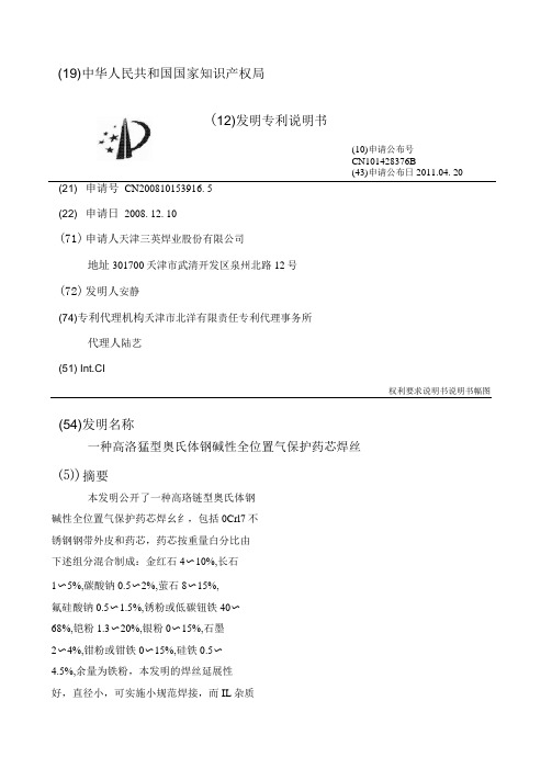
(19)中华人民共和国国家知识产权局
(12)发明专利说明书
(10)申请公布号
CN101428376B
(43)申请公布日2011.04. 20 (21) 申请号CN200810153916. 5
(22) 申请日2008. 12. 10
(71)申请人天津三英焊业股份有限公司
地址301700夭津市武清开发区泉州北路12号
(72)发明人安静
(74)专利代理机构夭津市北洋有限责任专利代理事务所
代理人陆艺
(51) Int.CI
权利要求说明书说明书幅图
(54)发明名称
一种高洛猛型奥氏体钢碱性全位置气保护药芯焊丝
⑸)摘要
本发明公开了一种高珞链型奥氏体钢
碱性全位置气保护药芯焊幺纟,包括0Crl7不
锈钢钢带外皮和药芯,药芯按重量白分比由
下述组分混合制成:金红石4〜10%,长石
1〜5%,碳酸钠0.5〜2%,萤石8〜15%,
氟硅酸钠0.5〜1.5%,锈粉或低碳钮铁40〜
68%,铠粉1.3〜20%,银粉0〜15%,石墨
2〜4%,钳粉或钳铁0〜15%,硅铁0.5〜
4.5%,余量为铁粉,本发明的焊丝延展性
好,直径小,可实施小规范焊接,而IL杂质
含量低,所以抗热裂性好;同时该焊丝具有
(10)申请公布号
CN101428376B
(43)申请公布日2011.04. 20。
Fiber-Optic Transmitter and ReceiverReliability Data IntroductionAgilent Technologies’ quality system includes an ongoing reliability monitor program to generate a data base from which this reliability data sheet is published.Transmitter Reliability The HFBR-0400 Series fiberoptic transmitters incorporate AlGaAs emitters and double lens optical systems. This design allows the HFBR-14XX transmitters to be driven at a relatively low current level for a specified amount of coupled power into the fiber. Because transmitter forward currents are proportional to failure rates, a low current translates into excellent transmitter reliability. To further improve reliability, Agilent has implemented a proprietary wafer screening technology that identifies dislocations whichcan lead to the formation of darkline defects (the primary mechanism for transmitter light output failures).HFBR-0400 SeriesTransmitters:HFBR-1402, -1412, -1404, -1414Receivers:HFBR-2402, -2412, -2406, -2416 Transmtter reliability data hasbeen calculated using 100 mAforward current and a 100% dutyfactor. In many actual useconditions, a 50% duty factor andlower forward currents are highlyprobable. When this is true,transmitter reliability will besubstantially better. The degree ofimprovement can be projected byexamining the footnotes below theHFBR-14XX data.Reliability PredictionModelThe reliability prediction modelused to project failure rate andmean time to failure (MTTF) atvarious temperatures shown in thesecond table assumes anexponential cumulative failurefunction (constant failure rate).The Arrhenius temperaturederating equation is used. AgilentTechnologies assumes no failuremechanism change between stressand use conditions. A conservativeactivation energy of 0.43 eV wasused and is derived from MIL-HDBD-217 for hybrid devices.Confidence intervals are basedupon the chi-squaredprediction method associated withexponential distributions.Fiber-Optic TransmitterReliability Data HFBR-1402HFBR-1412HFBR-1404HFBR-1414High Temperature Operating Life TestA. Demonstrated PerformanceTest Equivalent Test Condition Samples Device Hours Failures HTOL T A = 85°C, I F = 100 mA880 units879,5003B. Failure CriteriaFailure has occurred when the unitfails catastrophically, or when thelight output power decreases 3 dB.Point Typical PerformancePerformance [1]in Time [2]in Time(90% Confidence) Ambient Junction MTTF [1]FITs [3]MTTF [2]FITs [3] Temperature (°C)Temperature (°C)(hours)(/109 Hours)(hours)(/109 Hours) 85100293,0003411131,00075968095352,0002844158,00063347590424,0002360190,00052557085514,0001947231,00043376580626,0001598281,00035606075766,0001305344,00029055570945,0001059424,000235750651,172,000854526,000190145601,462,000684657,000152340551,838,000544825,000121235502,326,0004301,044,00095830452,965,0003371,331,00075125403,810,0002631,711,000585C. Failure Rate Prediction for Random Failures (I F @ 100 mA, 100% duty cycle)Notes:1. The point MTTF (representing an esti-mate of the mean point MTTF) is the total device hours divided by either the number performance that is expected from 90% ofall samples. This confidence interval isbased on the statistics of the distribution offailure rates prior to the onset of wear out.Refer to MIL-STD-690 for details of thismethodology.Fiber-Optic Link ReceiverReliability DataHFBR-2402HFBR-2412High Temperature Operating Life TestA. Demonstrated PerformanceTest Equivalent Test Condition Samples Device Hours Failures HTOL T A = 85°C, V CC = 5.25 V3,9602,370,0001B. Failure CriteriaFailure has occurred when the unitfails catastrophically. One devicefailed to switch logic states.Point Typical PerformancePerformance [1]in Time [2]in Time(90% Confidence) Ambient Junction MTTF [1]FITs [3]MTTF [2]FITs [3] Temperature (°C)Temperature (°C)(hours)(/109 Hours)(hours)(/109 Hours) 851002,370,000421609,0001,64080952,880,000346742,0001,34075903,530,000282909,0001,09070854,350,0002291,120,00089265805,400,0001841,390,00071960756,740,0001481,730,00057655708,480,0001172,180,000458506510,700,000932,750,000362456013,600,000733,510,000284405517,500,000564,520,000221355022,700,000435,850,000170304529,700,000337,650,000130254039,200,0002510,000,00099C. Failure Rate Prediction, Receiver (V CC = 5.25 V)Notes:1. The point MTTF (representing an esti-mate of the mean point MTTF) is the total device hours divided by either the number performance that is expected from 90% ofall samples. This confidence interval isuseful life failures. Refer to MIL-STD-690 fordetails of this methodology.Fiber-Optic Link ReceiverReliability DataHFBR-2406HFBR-2416High Temperature Operating Life TestA. Demonstrated PerformanceTest Equivalent Test Condition Samples Device Hours Failures HTOL T A = 85°C, V CC = 5.25 V2,2502,250,0000B. Failure CriteriaFailure has occurred when the unitfails catastrophically.Point Typical PerformancePerformance [1]in Time [2]in Time(90% Confidence) Ambient Junction MTTF [1]FITs [3]MTTF [2]FITs [3] Temperature (°C)Temperature (°C)(hours)(/109 Hours)(hours)(/109 Hours) 851002,250,000444977,164102380952,698,5163711,171,95385375903,252,6873071,412,62770870853,941,1732541,711,63358465804,801,4322082,085,24048060755,882,7441702,554,84939155707,250,3821383,148,80831850658,991,4071113,904,927256456011,222,799894,874,010205405514,102,949716,124,846163355017,848,023567,751,315129304522,755,516449,882,616101254029,238,4093412,698,10779C. Failure Rate Prediction, Receiver (V CC = 5.25 V)Notes:1. The point MTTF (representing an esti-mate of the mean point MTTF) is the total device hours divided by either the number performance that is expected from 90% ofall samples. This confidence interval isuseful life failures. Refer to MIL-STD-690 fordetails of this methodology.HFBR-0400 Mechanical and Environmental Test Data [1]MIL-STD-883D Units Total Test Name Reference Test Conditions Tested Failed Temperature Cycle1010500 cycles from -55 to +125°C, 15 minutes20201at extremes, 5 minutes transfer. [1]HFBR-1414500 cycles from -55 to +125°C, 15 minutes20900at extremes, 5 minutes transfer.[1]HFBR-2416 85/85T A = 85°C, 85% relative humidity,21407No bias, duration = 1,000 hours. [1]HFBR-1414T A = 85°C, 85% relative humidity,22206V CC = 5 volts, Duration = 1,000 hours[1]HFBR-2416 High Temperature1008T A = 125°C800 Storage Condition B1000 hoursResistance to2015Three 1 minute immersions.200 Solvents Brush after solvent immersion.Chemical Resistance— 5 minutes in Acetone, Methanol, Freon TF200and Boiling WaterVibration Variable 2007,20 G min., 20 to 2000 Hz.200 Frequency Condition B4, 4 minute cycles each X, Y, and Z.Thermal Shock1011-55°C to +125°C, 15 cycles600Condition B 5 min. dwell / 10 sec. transferMechanical Shock2002, 5 blows each X1, X2, Y1, Y2, Z1, Z2600Condition B1500 G, 0.5 msec. pulse.Port Wear Test [2]T A = 25°C500 connectorings200Less than 1 dBm variationConnector Side T A = 25°C 1 kg side load100 Load [3]Less than 1 dBm variationPort Strength [4]T A = 25°C 6 kg-cm (5.21 inch-lbs), no port damage100 Seal-Dye Penetrant101445 psi, 10 hours200 (Zyglo)Condition D No Leakage into microelectronic cavitySolderability2003245°C300 ESD Method 3015Human body model @ 10,000 V50HFBR-1414Human body model @ 2,000 V50HFBR-2402Human body model @ 1000 V50HFBR-2416Notes: See following page.Notes:1. Devices were preconditioned with 10 second, 260°C solder dip and 20 cycles, -40°C to 85°C, temperature cycle.2. Coupled power measurements were maximized before and after stress in determining the 1 dBm variation for SMA HFBR-0400 products. HFBR-0400 ST products do not require this due to the improved coupling design.3. The Connector Side Load test was only applied to HFBR-0400 SMA products. The Connector Side Load testing required that the housing be held so to prevent the leads from yielding. The load was applied through a SMA connectored fiber optic cable, perpendicular to the port. The product family is designed to limit cable and ferrule damage due to cable loading. The support and active leads should yield before damage to the cable or connector occurs. If extreme mechanical abuse of the cable/ connector is anticipated please contact Agilent’s Application Department for suggestions about mechanical strain relief. Due to the spring loaded feature of the ST connector, HFBR-0400 ST products will experience 1 dBm coupled power variation at a side load of less than 1 kg.4. The Port Strength test was designed to gauge the concerns with hand tightening the connector to the fiber optic port. The limit is set to alevel beyond most reasonable hand fastening loading.5. Package tests are defined as stresses that indicate the environmental strength of the package. Units tested indicate the total number of devices taken from the product family. While not all part numbers have been subjected to each stress, worst case products have been included.。