Sheet Metal Feature-钣金
- 格式:pdf
- 大小:4.32 MB
- 文档页数:68
Pro/ENGINEER 钣金件展平得技巧总结关于展平展平特征展平钣金件上得任何弯曲曲面, 无论它就是折弯特征还就是弯曲得壁。
•有三种展平类型可用:•规则 (Regular) - 展平零件中得大多数折弯。
选取要展平得现有折弯或壁特征。
如果选取所有折弯, 则创建零件得平整形态。
过渡 (Transition) - 展平不可展开得曲面, 如混合壁。
选取固定曲面并指定横截面曲线来决定展平特征得形状。
剖截面驱动 (Xsec Driven) - 展平不可展开得曲面, 如折边及法兰。
选取固定曲面并指定横截面曲线来决定展平特征得形状。
创建展平时, 要求指定要保持固定得曲面或边。
您得选择会改变模型得缺省视图。
尝试并拾取要保持在同一位置得主要曲面。
如果可能, 在创建几个展平特征时, 要保持一致, 并使用同一曲面。
设置自动固定得几何元素(“设置”(Set Up)>“固定几何”(Fixed Geom)), 可节省设计时间与保持一致性。
在展平后所创建得特征都就是该展平得子项/从属于该展平。
如果只就是临时展平零件, 并不需要该展平来保持设计意图, 则应删除该展平。
如果保持该展平, 只会在模型树中挤满多余特征, 这将延长零件再生时间。
切记, 如果删除得展平中含有在其后创建得特征, 这些附加特征也将被删除。
要草绘那些由于几何复杂与不规则而不能展平得壁得平整状态, 可使用 Metamorph 选项。
利用“变形控制”(DEFORM CONTROL) 菜单, 可加亮与草绘相应变形区域得轮廓。
展平特征创建后, 壁得成形状态隐含, 而平整状态处于活动状态。
当选取“展平全部”(Unbend All) 时, 就可使用展平对话框中得“变形控制”(DEFORM CONTROL) 菜单。
展平不可展开得曲面未展开(变形得)得曲面, 如具有复杂弯曲曲面得壁特征, 通常必须展平后才能制造。
要展平变形得材料, 该展平必须要简单。
定义得规则为所有要被展平得曲面必须具有外侧边或与一个有外侧边得区域相邻。

钣金英语词汇钣金英语词汇--中英文对照•钣金(Sheet Metal)o 比较钣金设计方法(Comparing Sheet Metal Design Methods)o 从实体设计钣金(Design Sheet Metal from Solids)o 将实体转换到钣金(Converting Solids to Sheet Metal)o 从展开状态设计(Designing from the Flattened State)o 从展开状态转换到钣金(Converting from Flattened State to Sheet Metal)o 转换到钣金的好处(Advantages of Conversion to Sheet Metal)o 组合不同的钣金设计方法(Combining the Different Sheet Metal Design Methods)• 使用钣金工具(Using Sheet Metal Tools)o 查看 FeatureManager 设计树(Examining the FeatureManager Design Tree)o 基体法兰(Base Flange)o 钣金薄片(Sheet Metal Tab)o 边线法兰(Edge Flange)o 斜接法兰(Miter Flange)o 褶边(Hem)o 绘制的折弯(Sketched Bend)o 闭合角(Closed Corner)o 展开钣金折弯(Flattening Sheet Metal Bends)o 转折(Jog)o 断开边角/边角剪裁(Break Corner/Corner Trim)o 放样的折弯(Lofted Bends)o 展开/折叠(Unfold/Fold)o 切口(Rip)• 在钣金中使用成形工具(Using Forming Tools with Sheet Metal)o 成形工具(Forming Tools)o 生成成形工具(Creating Forming Tools)o 定位成形工具(Positioning Forming Tools)o 将成形工具应用到钣金零件(Applying Forming Tools to Sheet Metal Parts)• 转换实体到钣金(Converting Solid Bodies to Sheet Metal)o 折弯类型(Bend Types)o 使用尖角折弯生成钣金零件(Creating a Sheet Metal Part Using Sharp Bends)o 使用圆角折弯生成钣金零件(Creating a Sheet Metal Part Using Round Bends)o 生成带圆锥面的钣金零件(Creating Sheet Metal Parts with Conical Faces)o 添加薄壁到钣金零件(Adding Walls to a Sheet Metal Part)o 钣金特征(Sheet Metal Features)o 输入钣金零件到 SolidWorks(Importing a Sheet Metal Part to SolidWorks)o 展开钣金折弯(Flattening Sheet Metal Bends)• 钣金零件(Sheet Metal Parts)o 自动切释放槽(Auto Relief)o 编辑折弯(Edit Bends)o 平板型式(Flat Pattern)o 镜(Mirror)o 通过钣金折弯的切除(Cut Across Sheet Metal Bends)o 生成带圆柱面的钣金零件(Creating Sheet Metal Parts with Cylindrical Faces)o 生成钣金零件的工程图(Creating Drawings of Sheet Metal Parts)o 生成钣金平板型式的配置(Creating a Sheet Metal Flat Pattern Configuration)o 钣金规格表 (Sheet Metal Gauge Table)">o 钣金选项(Sheet Metal Options)• 使用钣金折弯参数(Using Sheet Metal Bend Parameters)o 折弯系数选项(Bend Allowance Options)o 折弯系数与折弯扣除(Bend Allowance and Bend Deduction)o K-因子(K-factor)o 折弯系数表概述(Bend Table Overview)。
钣金udf拆分技巧
钣金(Sheet Metal)UDF(User Defined Feature)拆分技巧是指将钣金件的设计特征以UDF形式拆分,以便在后续的设计和装配过程中更方便地修改、管理和重复使用。
以下是一些钣金UDF拆分技巧:
1.标准元件创建:将常用的钣金构件(如孔、凸台、沉头螺
栓等)创建为标准元件,并以UDF形式保存。
这样可以在
需要时直接插入,并根据实际情况调整参数和尺寸,提高
设计效率。
2.特征拆分:根据钣金件的特点,将其重要特征拆分为单独
的UDF。
例如,将折边、弯曲、压合等特征拆分为相应的
UDF。
这样可以在需要时单独修改,同时确保设计的一致
性和重复使用性。
3.参数化设计:在创建UDF时,合理使用参数化设计。
通过
设置参数,可以方便地调整尺寸、角度、距离等,从而灵
活适应不同场景的使用需求。
4.命名和分类:对创建的UDF进行良好的命名和分类。
例如,
按照不同的构件类型和功能进行分类,便于查找和管理。
5.文件管理:将所有的UDF保存在统一的目录下,并定期备
份。
这样可以确保UDF的可用性和长期的管理维护。
通过合理拆分和使用钣金UDF,能够大大提高钣金设计的效率和精确度,减少重复工作,同时也方便了后续的修改和装配。
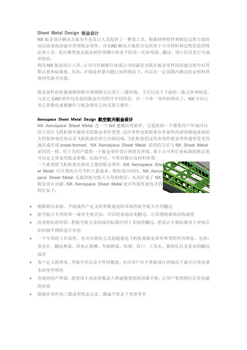
Sheet Metal Design 钣金设计NX钣金设计解决方案为专业设计人员提供了一整套工具,根据材料特性和制造过程方面的知识高效地创建并管理钣金零件。
该CAD解决方案组合包括用于合并材料和过程信息的特征和工具,允许模型表达钣金制作周期中的各个阶段-比如弯曲、翻边、切口以及其它可成形特征。
利用NX钣金设计工具,公司可以根据行业或公司的最佳实践在钣金零件的创建过程中应用默认值和标准值。
比如,在制造质量问题已知的情况下,可以在一定范围内确定给定材料厚度的弯曲半径值。
钣金部件的折叠视图和展开视图既可以用于三维环境,又可以用于下游的二维文件和制造。
与其它CAD软件包里面的钣金应用程序不同的是,在一个单一零件的情况下,NX可以让其它参数化建模操作与钣金特征之间实现互操作。
Aerospace Sheet Metal Design 航空航天钣金设计NX Aerospace Sheet Metal 是一个NX建模应用软件,它提供的一个聚焦用户环境可以用于设计飞机机架中最常见的钣金零件类型。
这些零件包括附着在外部和内部浇铸线表面的支持筋和承托架以及飞机机架的其它内部结构。
飞机机架的这些非线性钣金零件通常是采用液压成形或break-formed。
NX Aerospace Sheet Metal 采用的方法与NX Sheet Metal 采用的一样,用于为用户提供一个钣金零件设计的优化环境。
基于公司和行业标准的默认值可以定义常见的钣金参数,比如半径、中性因数以及材料厚度。
一个典型的飞机机架里面有大量的钣金零件。
NX Aerospace Sheet Metal 可以帮助公司节约大量成本,缩短设计时间。
NX Aerospace Sheet Metal 还提供航空航天专用的特征,从而扩展了NX钣金设计功能。
NX Aerospace Sheet Metal设计环境里面包含的特征如下:∙根据相关表面、平面或用户定义的参数建造的非线性航空航天专用翻边∙航空航天专用的单一或孪生啮合扣,可以轻易地改变翻边,让其围绕相邻结构成型∙改变特征的形状,把航空航天业的成形标准应用于非线性翻边,把设计手册标准用于对啮合扣的展平图样进行补偿∙一个专用的工作流程,允许以简化方式创建建造飞机机架钣金零件所需的所有特征,包括:发光孔、翻边释放、顶角止裂槽、弯曲释放、焊缝、切口、工具孔、紧固孔以及复杂的翻边成形∙客户定义的厚度、弯曲半径以及中性因数值,允许用户在不重新设计的情况下就可以更改基本的零件特性∙直观的用户界面,提供用于动态参数录入和建模预览的屏幕手柄,让用户看到他们正在创建的内容∙能够在零件的三维成型状态以及二维扁平状态下查看零件钣金部件的折叠视图和展开视图既可以用于三维环境,又可以用于下游的二维文件和制造。

钣金设计及制造常用英语(中英文对照表)第一篇:钣金设计及制造常用英语(中英文对照表)钣金英语声明:此资料本人借鉴了网上可查的资料,进行了编辑整。
此文档用来朋友们免费共享,促进学习,提高工作中的英语水平,无其他目的,特此声明!常见钣金设计术语中英文对照表表一工程图面中最常用的专用术语中文名称英文名称向上抽孔upward extrude[ek'stru:d] 压线score向下抽孔downward extrude 垫脚locator正面压螺母(钉)(柱)positive pressing nut(screw)(standoff)色拉孔counter sink反面压螺母(钉)(柱)negative pressing nut(screw)(standoff)向上凸点upward bump正面色拉孔positive counter sink 向下凸点downward bump 反面色拉孔negative counter sink 向上半剪upward half-shear 向上抽芽孔upward threaded hole 向下半剪downward half-shear 向下抽芽孔downward threaded hole 半剪half-shear 向上反折压平upward folding and flattening 接地标志ground symbol向下反折压平downward folding and flattening 螺柱standoff 点焊spot weld 穿孔(通孔)through hole 丝印silk screen 抽引,抽凸draw, extrude攻芽tap【机械工程】丝锥;螺丝攻冲孔pierce(piercing)沉孔counterbore 断差offset变形deformation 压平(两个料厚)hem在(管子等)里面攻出螺纹钣金英语成形form(forming)向上抽引,抽凸upward draw, form 凸点bump向下抽引,抽凸downward draw, form 拉钉rivet扩孔enlarge hole;broaching 规格大小specification 代号mark 数量amount 加工性质character 备注instruction表二钣金设计中常用的其它术语中文名称英文名称自铆self-clinching 全周压毛边all round burr 平头拉钉set-head rivet 表面处理finish定位销dowel pin ['dauəl]木钉,榫钉,夹缝钉,暗榫,暗销挂钩hook平头铆钉closed-end rivet 焊接线weld line塑料固定栓fastener, plastic push-type压合胶粘剂pressure sensitive adhesive [əd'hi:siv] 尼龙绑带nylon tie wrap ['nailɔn] 五金件hardware泡棉静电导片foam, EMI gasket ['ɡæskit] 贴纸labeling铍铜静电导片gasket, becu, EMI烤漆baking finish, stoving varnish, paint 圆头螺钉button-head screw 电镀plating, electroplate平头螺母flush nut 铭板nameplate平齐自铆flush self-clinching 包装packing 紧固螺丝fix screw铁材零件sheet metal parts 组装assembly 塑料零件plastic parts 凹陷,顶针sink mark 压边铆钉open-end rivet插孔jackn.千斤顶;插座;男人弹簧螺丝spring screw表三钣金制造中常用的其它术语钣金英语中文名称英文名称厚度thick 文字,记号character 半冲孔spring slice 角corner基座chassis['ʃæsi] 自锁螺母self-clenching nut 承座,支架,托架bracket轴肘式铆接toggle lock肘节;肘环套接,肘节装置,套环vt.拴牢,系紧承架horsing8.【体操】鞍马;跳马;9.晾晒架,支架,锯木架卡尺caliper 下盖base打印字模stamp letter 去毛边deburring 反面farside 正面inside下料blank(blanking)去除remove 拉孔broaching装配assembling 铸造found流体动力学fluid dynamics 流体力学fluid mechanics 加工machining液压hydraulic pressure 切线tangent机电一体化mechanotronics, mechanical-electrical integration 气压air pressure pneumatic pressure 稳定性stability表四钣金制造中常用的其它术语英文名称中文名称Cutting:切割socket weld承插焊接n.插座;窝,穴;牙糟fillet weld角焊,填角焊【机械学】圆角;嵌条;填角焊缝 branch connection分支接续fabrication tolerance.制造容差local heat treatment局部热处理adj.局部的;当地的 threaded pipe螺纹管seal welding密封焊接flange joint凸缘接头undercut底切feeder馈(电)线,馈路 conduit outlet 电线引出口钣金英语seal fitting密封接头, 密封配件Screw thread lubricant螺纹润滑剂['lu:brikənt] Seal绝缘层 weld reinforcement 焊缝补强lock washer锁紧[止动, 防松]垫圈electrical panel.配电板, 配电盘nipple螺纹接头zinc plated.镀锌的ring joint环接, 围缘接合bolt螺栓control:National Electrical Code master scheduletorque wrenchjob siteflange connectionHard hat:Goggles:stockpilepacking listcrate:purchased material listback-feedwire coilNPT thread.cable gland terminal blockpower drillconnector.insulated sleeve wire connectorwire terminalcontrol wiringmotor leadpower wiringtender document.orifice plate.flange gasket dimensional inspectionburn throughpiping system reinforcement of weld fabricationdye penetrant examination magnetic particle examination girth weldcement lined piping控制器全国电气规程主要图表, 综合图表, 设计任务书, 主要作业表转矩扳手施工现场.凸缘联接安全帽护目镜贮存装箱单柳条箱原材料进货单反馈线盘,线卷,美国标准锥管螺纹电缆衬垫线弧, 接头排接线盒, 接线板, 线夹机械钻接线器绝缘套管接线器电线接头控制线路电动机引出线电力布线提供证件挡板法兰垫片尺寸检验烧蚀.管道系统加强焊缝.制造染料渗透试验法磁粉检验环形焊缝水泥衬里钣金英语weld joint焊缝, 焊接接头spool drawing管路图, 管路详图spot test抽查, 当场测试butt weld对接焊缝Random Radiography随机射线照相检查X光线照相(术)radiographic examination射线照相检查erection架设examination试验cable tray.电缆盘rigid steel conduit钢制电线管1.坚硬的,刚硬的;刚性的;不易弯的 power control arc weldingcontrol cablenormal bendcable glands:exfoliationpower receptaclegrounding conductorlighting fixturejunction boxrace wayterminal boxdistribution boardreceptacletumble switchcathodic protection systemCircuit breakeramplifier panelcontrol consoleelectrical materialconvenience receptacle.cable gland TIG: Tungsten-arc Inert-Gas welding filler rodtensile strengthshield gasshield jighigh frequency generator.welding rod filler metalshop fabricationfield installationwelding beadboth sides welding.residual stress功率控制电弧焊控制电缆操纵索法向[法线]弯管5.【数学】法线;正交电缆衬垫剥落[eks,fəuli'eiʃən]电力插座.接地导体照明器材分线箱电缆管道接线盒配电盘, 配电屏插座【电工学】插座;插孔。
钣金, (Metal Plate; SheetMetal in English),钣金至今为止尚未有一个比较完整的定义,根据国外某专业期刊上的一则定义可以将其定义为:钣金是针对金属薄板(通常在6mm以下)一种综合冷加工工艺,包括剪、冲/切/复合、折、焊接、铆接、拼接、成型(如汽车车身)等。
其显著的特征就是同一零件厚度一致。
钣金工厂一般来说基本设备包括剪板机(Shear Machine)、数控冲床(CNC Punching Machine)/激光、等离子、水射流切割机(Laser,Plasma, Waterjet Cutting Machine)/复合机(Combination Machine)、折弯机(Bending Machine)以及各种辅助设备如:开卷机、校平机、去毛刺机、点焊机等。
通常,钣金工厂最重要的四个步骤是剪、冲/切、折,焊接,表面处理等。
钣金有时也作扳金,这个词来源于英文platemetal,一般是将一些金属薄板通过手工或模具冲压使其产生塑性变形,形成所希望的形状和尺寸,并可进一步通过焊接或少量的机械加工形成更复杂的零件,比如家庭中常用的烟囱,铁皮炉,还有汽车外壳都是钣金件。
金属板材加工就叫钣金加工。
具体譬如利用板材制作烟囱、铁桶、油箱油壶、通风管道、弯头大小头、天圆地方、漏斗形等,主要工序是剪切、折弯扣边、弯曲成型、焊接、铆接等,需要一定几何知识。
钣金件就是薄板五金件,也就是可以通过冲压,弯曲,拉伸等手段来加工的零件,一个大体的定义就是- 在加工过程中厚度不变的零件. 相对应的是铸造件,锻压件,机械加工零件等,比如说汽车的外面的铁壳就是钣金件,不锈钢做的一些橱具也是钣金件。
现代钣金工艺包括:是灯丝电源绕组、激光切割、重型加工、金属粘结、金属拉拔、等离子切割、精密焊接、辊轧成型、金属板材弯曲成型、模锻、水喷射切割、精密焊接等。
钣金件的表面处理也是钣金加工过程非常重要的一环,因为它有防止零件生锈,美化产品的外观等作用。

钣金英语词汇拉孔broaching装配assembling铸造found流体动力学fluid dynamics流体力学fluid mechanics加工machining液压hydraulic pressure切线tangent机电一体化mechanotronics mechanical-electrical integration气压air pressure pneumatic pressure稳定性stabilityCutting:切割socket weld 承插焊接fillet weld 角焊,填角焊branch connection 分支接续fabrication tolerance 制造容差local heat treatment 局部热处理threaded pipe 螺纹管seal welding 密封焊接flange joint 凸缘接头undercut 底切feeder 馈电线conduit outlet 电线引出口seal fitting 密封接头, 密封配件Screw thread lubricant 螺纹润滑剂Seal:绝缘层weld reinforcement 焊缝补强lock washer 锁紧[止动, 防松]垫圈electrical panel 配电板,配电盘nipple 螺纹接头zinc plated 镀锌的ring joint 环接, 围缘接合bolt 螺栓control:控制器National Electrical Code 全国电气规程master schedule 主要图表, 综合图表, 设计任务书, 主要作业表torque wrench 转矩扳手本文介绍了钣金设计软件一般都是英文界面的,为了便于大家尽快熟悉界面,特规整了钣金英语词汇。
job site 施工现场flange connection 凸缘联接Hard hat:安全帽Goggles:护目镜stockpile 贮存packing list 装箱单crate:柳条箱purchased material list 原材料进货单back-feed 反馈wire coil 线盘,线卷NPT thread 美国标准锥管螺纹cable gland 电缆衬垫terminal block 线弧, 接头排,接线盒, 接线板, 线夹power drill 机械钻connector 接线器insulated sleeve 绝缘套管wire connector 接线器wire terminal 电线接头control wiring 控制线路motor lead 电动机引出线power wiring 电力布线tender document 提供证件orifice plate 挡板nut 螺母flange gasket 法兰垫片dimensional inspection 尺寸检验burn through 烧蚀piping system 管道系统reinforcement of weld 加强焊缝fabrication 制造dye penetrant examination 染料渗透试验法magnetic particle examination 磁粉检验girth weld 环形焊缝cement lined piping 水泥衬里weld joint 焊缝, 焊接接头spool drawing 管路图, 管路详图spot test 抽查, 当场测试butt weld 对接焊缝Random Radiography 随机射线照相检查本文介绍了钣金设计软件一般都是英文界面的,为了便于大家尽快熟悉界面,特规整了钣金英语词汇。
Sheet Metal Design1-A | 9:00 - 10:15 amInstructor: Jonathan LanderosNew functionality and workflow improvements made this workshop a must-attend for anyone working in sheet metal design. Jonathan Landeros discussed Inventor’s Sheet Metal tools including Lofted Flange, Contour Roll, and Unfold/Refold, which can help make designs accurate while reducing manufacturing error costs. He also demonstrated how templates, bend tables, and Content Center Fasteners will standardize sheet metal design and manufacturing.ContentsSheet Metal Styles (2)Sheet Metal Tools (7)Creating a Sheet Metal part (31)Sheet Metal StylesStylesThe foundation of creating sheet metal components are the sheet metal rules that define them. Creation of accurate sheet metal rules can save an enormous amount of preliminary work when designing sheet metal parts. Sheet metal rules are set in the Standards and Styles editor. A good set of standards addressing both industry standards (such as standard sheet metal gauges), and company standards (such as bend allowances) can save time in the creation of a part.When saved to the Styles library and used as a standard to create as many sheet metal components as possible (Ideally all of them!). Then that savings multiplies across the entire organizationSheet Metal Rules contain the default parameters used by the component to create its features and define its properties. Multiple rules can be created to reflect different thickness, bend radii, and materials.Sheet TabMaterial – Opening this pull down menuallows you to select a material from thestyles library.Thickness – Type in a value to definethe sheet metal thickness for this rule.Unfold Rule – Sets the unfolding rule to one of the following•Linear (k-factor) – A value between 1 (outside edge)and 0 (inside edge) defining the neutral axis wherematerial neither bends, nor compresses. It uses theequation: Unfolded length = (inner Bend Radius+ KFactor*Thickness)*(2*PI*Bend Angle/360)bend angle in degrees•Bend table –Allows the creation of a bend allowancetable.•Custom Equation – Allows the creation of customequations for the generation of a bend allowance.Miter/Rip/Seam Gap – Sets the default value of the gap forthese types of features when they’re created.Flat Pattern Bend angle – Defines which angle (A or B) is reported as the bend angle when flat patterns are generated.Flat Pattern Punch Representation – When a punch feature exists, this defines how it is shown in the flat pattern. There are four choices:Formed Punch Feature – This option displays the SheetMetal Punch as a three-dimensional feature•2D Sketch Representation – This option desplaysthe Sheet Metal Punch as a 2D representationwhich is created and defined by the user.•2D Sketch Representation and Center Mark – Thisoption displays the sheet metal punch using apreviously defined sketch, but also shows a user-defined center mark defining the punches location•Center Mark Only – Displays a user defined center mark to represent the punchRelief shape defines the default shape of the relief for bent features such as flanges, hems, and contour flanges.•Straight – This is a ‘square’ bend relief with sharp corners. Often created by manual processes such as a saw.•Tear – In essence, this is ‘no relief’ where the material shears next to the bend.•Round – Bend relief with a full radius end. Often created using automated processes such as laser technology.The Straight and Round reliefs have parameters have the following parameters that can be controlled. The Tear relief only has the minimum remnant ‘C’ available.o‘A’ defines the bend relief widtho‘B’ indicates the bend relief depth beyond the deformation zone (i.e. the tangency of the bend)o‘C ‘represents the size of the material allowed to remain after the bend and relief are created, or ‘minimum remnant’.Bend Transition defines the type of transition made across a bend in the flat pattern. The available types are:•None – Results in a spline across the bend in the flat pattern•Intersection – Results in a straight line across the transition•Arc – Results in an arc across the transition•Trim to Bend – Results in a cut to the bend zone, following along the bend’s tangencyThe screen under corner tab controls how a corner where either two or three bends meet are handled. The following options are available:2 Bend TransitionRound - A corner relief defined by a circular cutout in the flat. The cutout has acenter placed on the intersection of the bend linesSquare – A relief shape with a square cutout centered on the bend line intersectionTear – A relief shape defined in flat by extending the flange edges to theirintersection. Named due to material failure caused by tearing across the bend zonein the folded model.Trim to Bend – This corner relief is defined by a polygonal cut out bounded by thebending zone lines.Arc Weld - A corner relief shape defined in the flat by curves tangent to the flangeedges. These edges follow along the outside edge of the bend zone whichconverge to a flat gap equal to the Miter Gap value. folded model by a gapbetween the flanges that is equidistant along the length of the relief suitable forsubsequent arc welding hence the term ‘Arc Weld’.3 Bend IntersectionUse this option to define the Default corner relief to display in the flat pattern when 3 bends intersect.Note: The folded model does not display the selected relief option.No Replacement As indicated, no replacement of the "as modeled" geometry ismade in the flat pattern.Intersection A corner relief shape defined in the flat by extending and intersectingthe flange edges.Full Round A corner relief shape defined in the flat by extending the flange edgesto their intersection and then placing a fillet tangent to the bend zone tangencylines. Radius will likely be larger than what would be produced using the Roundwith Radius option.Round with Radius A corner relief shape defined in the flat by extending theflange edges to their intersection, and then placing a tangent fillet of the sizespecified. Radius will likely be smaller than what would be produced by the FullRound option.Sheet Metal ToolsFlat PatternFlat Pattern is another way that sheet metal design differs from part modeling. Sheet metal is designed from a flat face with bends and flanges added during the design. Generating a flat pattern is often necessary for documentation and manufacturing purposes.•The Flat Pattern tool calculates the material and layout required to flatten a 3D sheet metal model. The part browser displays a Flat Pattern node and the flattened state of the model isdisplayed when this node is active. The flat pattern updates automatically when you edit the 3D model.•The Flat Pattern is typically created normal to your initially sketched face feature, however there may be times when you need to adjust the orientation. Select Edit Flat Pattern Definition from the context menu when the Flat Pattern node is selected to access orientation options.•Features that require material deformation, such as louvers or dimples, cannot be flattened. If these features are placed using the Punch Tool onto sheet metal faces, they are accuratelyrepresented as 3D features on the flat pattern. Optionally, they can be represented using aselected sketch or with a center mark. Sketched and placed features can have unpredictable results, so use the Punch Tool to add these shapes to your sheet metal part. •The Drawing Manager uses the flat pattern for the flat pattern view. The flat pattern must be created in the part before you can place a flat pattern view in the drawing. If you delete the flat pattern, the drawing also loses the flat pattern view.Note: If you create a model that cannot be unfolded (for example, the created flange features overlap in the flat pattern), the flat pattern request generates a warning dialog box indicating intersecting features. You can Edit or Cancel the dialog box or you can Accept the intersecting errors. If you accept, the flat pattern is developed with intersecting features. Subsequent feature creation in the folded model displays the dialog box until you edit the features which intersect in the flattened state. Editing Flat Pattern:•Features can be added to the flat pattern for clean-up purposes. These operations are typically performed to support shop-specific manufacturing practices.•Example A: A press break has a flat back stop, uneven or non-parallel edges will causemanufacturing additional set up steps. To ensure a consistent repeatable feature good practice it to make all bends parallel to edge contacting the backstop.•Example B: A short flange. If the press break has a min. 1/2-inch depth and a 3/8-inch flange is designed into the part the operator will need to perform additional set up when manufacturing the part.Face•A face is typically the base feature of a sheet metal part. To start, you sketch a profile that represents the shape of the face, and then you use the Sheet Metal Face command to create a face.• When creating a sheet metal face, you can create a bend between a new face and an existing face. The faces are automatically trimmed or extended as necessary to create the bend.•If the faces are parallel, but not coplanar, you can add a double bend. Depending on the distance between the faces, the bends are either trimmed so they are tangent or a new face is created between the two bends.•You can also override default sheet metal styles from the Face dialog box as you create your sheet metal face. These settings include how a flat pattern unfolds, and the bend relief settings between faces.FlangeUse the Flange tool on the Sheet Metal Features toolbar to add a sheet metal face and a bend to an existing sheet metal face. You can specify the depth and the angle of the flange, and whether it is created inside or outside the existing face. You can also specify the width or offset of the new flange.Shape tab Specifies:Edge - Allows designer to specify which edge the flange will be applied.Loop - Allows you to select an edge loop and will subsequently apply your flange to all edges of the selected loop.Flange Angle - Defines the angle of the flange relative to the face containing the selected edge(s). The field will accept numeric entries, formulas, parameters or measured values. Bend Radius – Defines the radius of the bend between the flange and the face containing the selected edge(s). The value defaults to the system parameter named: BendRadius which is defined on the Sheet Metal Styles dialog. The field will accept numeric entries, formulas, parameters or measured values.Height Extents - The upper field allows you to determine if the height of your flange will be defined by a specific Distance or by selecting To geometry.The lower field allows you to specify the height of your flange by entering a value and will accept numeric entries, formulas, parameters or measured values or it will allow you to select geometry andsubsequently enter an offset value to allow your flange to be determined by the position of other geometry on your part.Flip Direction - Allows you to flip the direction of the flange when the specified height is defined as Distance.Note: This functionality has been enhanced so that selecting Flip Direction uses the edge opposite from the selected edge while maintaining all other input flange parameters.Height Datum OptionsOuter Faces - Measures the flange height from the intersection of the outer faces. In the illustration below, the orange line indicates the outer faces.Inner Faces - Measures the flange height from the intersection of the inner faces. In the illustration below, the orange line indicates the inner faces.Parallel to Flange -Measures the flange height parallel to the flange face and tangent to the bend. In the illustration below, the orange line indicates the bend tangency line perpendicular to the flange face.Aligned VS Orthogonal - This control allows you to determine if the height measurement is aligned with the flange face or orthogonal to the base face. In the illustration below, the measurement on the left is aligned while the measurement on the right is orthogonal.Bend Position OptionsFour options allow you to select where your bend will be positioned relative to the extent of the face containing the selected edge(s).Outside of Base Face - Positions the outside face of the flange aligned with the intersection of the outside face and the selected edge. In the illustration below, the orange line indicates how the bend is positioned relative to the outside face and the selected edge.Bend from Adjacent Face - Positionsthe bend such that it starts at the edgeof the selected face. In the illustrationbelow, the orange line indicates wherethe bend of the flange will originate.Inside of Bend Face - Positions the bend such that the inside face of the resulting flange is aligned with the selected edge. In the illustration below, the orange line indicates how the bend is positioned relative to the inside face and the selected edge.Bend Tangent - Positions the bend tangent to the selected edge. In the illustration below, the orange line indicates the bend tangency condition relative to the selected edge.Unfold methods describes under Sheet Metal Styles.>> More Button: Specifies the extents of the flange: full edge, width, offset orfrom/to existing geometry.Edge - Creates a flange the full length of the selected face edge.Width - Creates a flange of a specified width at a specified offset from a single selectedvertex, work point, work plane or planar face on the edge of an existing face. Optionally,you are able to specify that the flange is a specific width centered on the mid-point ofthe selected edge.Offset - Creates a flange offset from two selected vertices, work points, work planes or planarfaces on the edge of an existing face.From To - Creates flange whose width is defined by selecting existing part geometry(vertices, work points, work planes or planar faces intersecting the defining edge) thatdefines the flange from and to extents.Old Method - This option is unchecked by default in new parts. When checked, this option disables the new functionality which provides more control over the bend positioning and measurement. When editing flange features on sheet metal parts created with releases prior to Autodesk Inventor 2008, this option will be checked allowing you to edit the feature with the control that was active when the feature was created. You may optionally uncheck this to obtain the full control provided.Contour Flange• Use the Contour Flange tool on the Sheet Metal Features toolbar to create a contour flange. This tool is only available if an unconsumed open profile exists in your part.The Shape tab specifies the: •Open profile which defines the contour of the flange•Edges to which the flange are applied•Radius of the bend •Offset direction of the material relative to the contour profileProfileSelect an unconsumed sketch that contains an open profile which defines the shape of your contourflange.Edge - Allows designer to specify which edge the flange will be applied.Loop - Allows you to select an edge loop and will subsequently apply your flange to all edgesof the selected loop.Edge Selection Notes:1. The edge selected for your contour flange must be perpendicular to the profile sketch plane.2. Multiple edges can not be selected if the following conditions exist:•The start or endpoint of your profile sketch is not coincident with the infinite line defined by the first selected edge •The extents option (on the More tab) is set to: Width, Offset, From-To or Distance • The selected profile contains geometry other than straight-line or circular arc segments3. When de-selecting edges from a multi-edge set you will not be allowed to de-select theprimary edge which satisfies the above criteria.OffsetOptionally changes the material thickness offset to the other side of the selected profile.•Bend Radius – Defines the radius of the bend between the flange and the face containing the selected edge or edges The value defaults to the system parameter (named BendRadius) which is defined on the Sheet Metal Styles dialog. The field will accept numeric entries, formulas,parameters or measured values.•Unfold Option, Bend and Corner discussed in Flange FeatureLofted FlangeLofted Flange creates a shape that is often referred to as the ‘Square to Round’ transition. Two sketches are used to define each end of the flange.ShapeProfile 1 – Selects first sketch used to create lofted FlangeProfile 2 – Selects the second sketch used to create the lofted flange.Flip Side – Click to offset the material thickness to the other side, or toboth sides of the selected profile.OutputDie Form – Creates rounded corners on the Flange, as if formed on a die.Press Brake – Enables faceted corners, as if formed in a press brake.Converge – Available only with press brake output, this option allows the flattened sections to convergenear a point.Facet Control – Allows the user to control the size of a facet using one of the following methods: •‘A’ Chord Tolerance – Value entered by the user determines the maximum distance from the arcsegment to the face segement.•‘B’ Facet Angle – Value entered by the user determines the maximum angle to the chord segment at the facet face vertex.•‘C’ Facet Distance – Value entered by the user determines the maximum width of the facet face (Length of Chord) when subdividing the arc profile.Bend RadiusBend Radius – Allows the user to enter a value for thelofted flange feature. This overrides the value set inSheet Metal styles.Unfold Rule – Drop-down selection that allows the userto choose an unfold rule that differs from that set in theSheet Metal StylesContour rollThe contour roll creates a rolled she metal feature using an open profile similar to revolving a contour flange around a bend. It’s analogy from the standard modeling environment is revolve.AccessShapeProfile: Used to select profile geometry.Axis: Used to select rotation axis. Note - Rotation axis geometry must becontained within the sketch containing the profile geometry.Flip Arrows: Click to offset the material thickness to the other side, or toboth sides of the selected profile.Rolled AngleRolled Angle: Allows the value of the angular sweep of the rolledsection to be enters. Defaults to 90 degrees. Note - angle value may notequal 360 degrees for multi-segment profiles. A Rolled Angle value of 360degrees can be used for profiles with a single, straight line.Flip Arrows: When active, click to sweep the Contour Roll in thedirection opposite of the previewed direction, or equally both clockwise,and counter-clockwise of previewed direction .Unfolding & UnrollingUnroll MethodDrop-down selection list allowing the selection of themethod used to unroll the Contour Roll feature. Thesemethods all derive a Developed Length by multiplying theRolled Angle by a Neutral Radius.They differ by the type of input provided:Centroid Cylinder - The default method, which uses an axis parallel to the revolution axis is passing through the evaluated Centroid location. This provides input to define a neutral cylindrical surface.Custom Cylinder - Allows selection of a sketched line to define the surface of the cylindrical neutral surface.Developed Length - Allows entry of an explicit value which drives the developed length of the flattened rolled segment.Neutral Radius - Allows a parametrically determined value for the neutral radius (when multi-segment profiles are considered).Unfold RuleDrop-down selection list allowing the selection of an Unfold Rule that differs from that specified in the active Sheet Metal RuleBend RadiusData entry field that allows you to change input of the value of the bend radius from the default (set by the Sheet Metal Defaults)HemA Hem is used to strengthen or to finish an exposed edge. The Hem tool to is designed to roll or fold an edge.1.Click the Hem tool.2.Click the drop-down arrow to choose Single, Teardrop, Rolled, or Double hem type.3.Under Shape:•Choose the face Edge and if desired, click the Flip Direction button.•Accept the default values set by the active sheet metal style or enter a value for the hem Gap and Length, or Radius and Angle, depending on the type of hem specified.4.Click the More button to specify Extents. Click the drop-down arrow to select:•Edge creates the hem on the selected edge.•Width sets an offset from a start point and a hem width.•Offset sets offsets for hem start and endpoints from selected points or planar faces intersecting the selected edge..•From/To starts and ends the hem from selected points or planar faces intersecting the selected edge.•If desired, click the down arrow to use Measure, Show Dimensions, or Parameter List to enter a value.5.Click Apply to continue to add hems or click OK to close the dialog box.BendUse the Bend tool on the Sheet Metal Features toolbar to create a bend between two sheet metal faces.You can create bends between sheet metal faces that are intersecting, at an angle, or parallel, but not coplanar. The model edges of the two sheet metal faces must be parallel to create a bend.Bend - Controls the selection of edges and the radius of the bend.Edges - Selects a model edge on each face. The bend is previewed. The sheet metal faces are trimmed or extended as necessary to create the bend.Radius - Specifies the radius for the bend.Double bend - If sheet metal faces are parallel, but not coplanar, you can create a double bend between the faces. Trims bends so they are tangent or a new sheet metal face is constructed to connect the bends.Fix Edges - Equal bends are added to the existing sheet metal edges.45 Degree - Sheet metal faces are trimmed or extended as necessary and 45 degree bends are inserted.Full Radius - Sheet metal faces are trimmed or extended as necessary and a full radius (half-circle) bend is inserted.90 Degree - Sheet metal faces are trimmed or extended as necessary and 90 degree bends are inserted.Flip Fixed Edge - By default, for 45 Degree, Full Radius or 90 Degree bends, the first selected edge is fixed and the second is trimmed or extended, if necessary. Select Flip Fixed Edge to reverse the order: the second selected edge is fixed and the first is trimmed orextended.Extend Bend Aligned to Side Faces - Extends material along thefaces on the side of the edges connected by the bend instead ofperpendicularly to the bend axis.Extend Bend - Extends material perpendicularly to the bend axis. Thisis the default option when the dialog is initialized.FoldUse Fold to bend a portion of a part. After you define the tangency location of the bend using a bend line, you can specify the side of the part to bend, the direction of the bend, and its angle, radius, or arc length.Using the Fold feature, you can bend a portion of a part. After you define the tangency location of the bend using a 2D Sketch line, you can specify the side of the part to bend, the direction of the bend, and its angle, radius, or arc length.Defining the Fold locationTo define the location of the bend, you must sketch an open profile consisting of a single line segment to serve as the bend line. The sketch plane on which that sketch is created serves as the neutral plane of the bend.Typically, place the sketch plane on the side of the part where the fold occurs or at the center of the fold. Also, place your sketch plane at a height where you can measure the results.Bend Line - The tangency line at which the existing part transitions into the bend feature'sdeformation area. The line about which the feature hinges or folds.•The Bend Part feature is defined by using 1 of 3 input combinations. Selecting 1 of the available combinations from the drop-down list alters the dialog box fields to allow appropriate inputs.• A bend line can be created using sketch or Inserted drawing geometry.Foldingspecific portions of a partThe most common Fold is a bend line that divides a part into 2 portions so that 1 or both portions can be bent. You can also bend specific portions of the part using the Bend Minimum option of a more complicated part by isolating them using the bend line.You can limit the length of the open profile so that it touches only the portion of the part that you wantto bend. By sketching the open profile directly on the face of the portion you want to bend, you bend 1portion of the part rather than multiple portions that may lie on the same projection direction of the open profile.Cut• The Cut tool functions much the same as the extrude feature.Profile• Selects a profile to remove material. If there are multiple profiles and none are selected, click Profile, and then click one or more profiles. The material to be removed is previewed in the graphics window.• If only a Single profile has been created the Single profile is Automatically selected and previews the cut.• If multiple profiles have been created the profiles will need to be selected manually.• Extents - Determines the method for ending the cut and sets its depth. Click the drop-down arrow to list the extent methods, select 1, and enter a value. Cuts can be a specific depth or canterminate on a work plane or sheet metal face. Click a direction button to flip direction or specify a mid-plane cut.• Distance - Default method. Establishes the depth and direction of the cut. The cut is perpendicular to the sketch plane.• To Next - Cut terminates on the next plane or face. Selects the direction for the cut.• To - Selects an ending face or plane on which to terminate the cut. You can terminate the cut on the selected face, or on a face that extends beyond the termination plane. In an assembly, the face or plane can be on another part.• From - To - Selects beginning and ending faces or planes on which to terminate the extrusion. In an assembly, the faces or planes can be on other parts.•All - Extrudes the profile through all features and sketches in the specified direction. Select the direction of the cut or extrude the cut equally in both directions. This functionality has been enhanced so that selecting Flip Direction uses the edgeopposite from the selected edge while maintaining all other input flange parameters.Cut Across BendExtent options are not available when cutting across a bend. Distance equal to Thickness will create a through cut while a distance less than Thickness will create a partial depth cut wrapped around bends.•Selects a profile to remove material by wrapping the profile across faces and one or more sheet metal bends. If there are multiple profiles and none are selected, click Profile and then click one or more profiles. The material to be removed is previewed in the graphics window.•If only a Single profile has been created the Single profile is Automatically selected and previews the cut.•If Multiple profiles have been created the profiles will need to be selected manually.Thickness•Wraps the cut across faces and bends with cut depth through thematerial Thickness.Thickness/"n"•Wraps the cut across faces and bends with cut depth equal toThickness/"n."Corner SeamUse the Corner Seam tool on the Sheet Metal Features toolbar to add a seam to 2 sheet metal faces or to Rip an edge to create a corner seam. Corner Seam tool controls the shape, seam, and gap parameters for the corner seam.•Shape - Selects model edges and specifies whether to rip corners.•Corner Seam - Specifies new corner geometry between existing coplanar or intersecting sheet metal faces.•Corner Rip - Specifies a ripped corner. Use this option to open a square corner to create a sheet metal corner seam (typically on a converted part model).•Edges - Tool for selecting a model edge on each face•Miter - This option controls the type of miter corner createdwhen the selected edges are on coplanar faces.。


第一篇钣金件的预处理和NX PDW工程概述第1章零件的预处理【本章目的】一般来说,使用Progressive Die Wizard(简称PDW)系统可以设计任何钣金模型的级进模。
PDW系统提供了多种工具来处理各种类型的实体模型,如参数化的实体模型、非参数化的实体模型以及带有自由成形曲面的实体模型。
用户可以根据具体的零件确定适合的方法。
对于自由成形曲面实体模型,通常不需要也不可能转换成钣金特征构成的实体模型,附件B详细介绍了这一类型零件的设计方法;对于直弯零件,可以转换成由钣金特征构成的实体模型,或直接用类似处理自由成形曲面实体模型的方法,或用其他工具如Direct Unfolding进行设计。
在设计模具之前,用户需要准备一个合适的零件模型。
本章将通过一个简单的实例,介绍如何准备一个由钣金特征构成的实体模型文件。
【本章目标】在完成本章学习后,你将能够:●识别出PDW适用的钣金零件模型。
●使用特征识别与重构功能,将任意实体模型转化成为具有设计特征的钣金零件模型。
1.1 概述使用PDW,你将能够:●自动完成级进模设计任务。
●生成数控加工所需要的完整的3D模型。
●当设计改变时,更改产品设计结果以保证数据的关联性。
UG NX4级进模设计培训教程2●更改和扩充模架库、组件库、工艺预定义库和标准件库。
●通过更改电子数据表格来定制对话框选项。
使用PDW需要从钣金零件开始,钣金零件独立于CAD系统平台,可以是由NX生成,也可以是由其他设计工具生成。
准备好钣金零件后,则可使用PDW进行模具的加工工艺设计和装配结构设计。
其中加工工艺设计包括:●工艺预定义(Feature Pre-Process),例如复合弯曲、成形、翻孔和修边等。
●零件的毛坯展开(Blank Generator),根据部件的形状生成毛坯的形状。
●毛坯排样(Blank Layout),设置和确定毛坯在条料中的位置和方向,同时确定条料的宽度、步距等。
●废料设计(Scrap Design),定义出需要从条料上去除的废料,并将废料细分。


钣金(Sheet Metal)比较钣金设计方法(Comparing Sheet Metal Design Methods)从实体设计钣金(Design Sheet Metal from Solids)将实体转换到钣金(Converting Solids to Sheet Metal)从展开状态设计(Designing from the Flattened State)从展开状态转换到钣金(Converting from Flattened State to Sheet Metal)转换到钣金的好处(Advantages of Conversion to Sheet Metal)组合不同的钣金设计方法(Combining the Different Sheet Metal Design Methods)•使用钣金工具(Using Sheet Metal Tools)查看FeatureManager设计树(Examining the FeatureManager Design Tree)基体法兰(Base Flange)钣金薄片(Sheet Metal Tab)边线法兰(Edge Flange)斜接法兰(Miter Flange)褶边(Hem)绘制的折弯(Sketched Bend)闭合角(Closed Corner)展开钣金折弯(Flattening Sheet Metal Bends)转折(Jog)断开边角/边角剪裁(Break Corner/Corner Trim)放样的折弯(Lofted Bends)展开/折叠(Unfold/Fold)切口(Rip)•在钣金中使用成形工具(Using Forming Tools with Sheet Metal)成形工具(Forming Tools)生成成形工具(Creating Forming Tools)定位成形工具(Positioning Forming Tools)将成形工具应用到钣金零件(Applying Forming Tools to Sheet Metal Parts)•转换实体到钣金(Converting Solid Bodies to Sheet Metal)折弯类型(Bend Types)使用尖角折弯生成钣金零件(Creating a Sheet Metal Part Using Sharp Bends)使用圆角折弯生成钣金零件(Creating a Sheet Metal Part Using Round Bends)生成带圆锥面的钣金零件(Creating Sheet Metal Parts with Conical Faces)添加薄壁到钣金零件(Adding Walls to a Sheet Metal Part)钣金特征(Sheet Metal Features)输入钣金零件到SolidWorks(Importing a Sheet Metal Part to SolidWorks)展开钣金折弯(Flattening Sheet Metal Bends)•钣金零件(Sheet Metal Parts)自动切释放槽(Auto Relief)编辑折弯(Edit Bends)平板型式(Flat Pattern)镜(Mirror)通过钣金折弯的切除(Cut Across Sheet Metal Bends)生成带圆柱面的钣金零件(Creating Sheet Metal Parts with Cylindrical Faces)生成钣金零件的工程图(Creating Drawings of Sheet Metal Parts)生成钣金平板型式的配置(Creating a Sheet Metal Flat Pattern Configuration)钣金规格表(Sheet Metal Gauge Table)钣金选项(Sheet Metal Options)•使用钣金折弯参数(Using Sheet Metal Bend Parameters)折弯系数选项(Bend Allowance Options)折弯系数与折弯扣除(Bend Allowance and Bend Deduction)K-因子(K-factor)折弯系数表概述(Bend Table Overview)。
By Christ Wang目 录一、 Sheet Metal 模组简介--------------------------------------------1二、 Sheet Metal 模组的基本功能--------------------------------------2三、 Model Sheet (钣件模型)------------------------------------------41. New Sheet(建立新钣件)-----------------------------------5 2. Add Sheet (增加钣件)------------------------------------10 3. Tools(标准冲头)------------------------------------------18 4. Attach (附属属性)----------------------------------------22 四、 Modify Sheet 修改钣件-----------------------------------------231. Bends(折弯)---------------------------------------------24 2. Lip(边线长料)--------------------------------------------29 3. Sheet(钣件)----------------------------------------------32 4. Sheet Features(钣金特征)-------------------------------33 5. Attach(附属属性)----------------------------------------36五、 Post Process (后处理)--------------------------------------------11. Post Process(后处理)----------------------------------------22. Inquire(查询属性)-------------------------------------------7六、 TDB Browser (TDB 浏览器)--------------------------------------9七、钣金客制化------------------------------------------------------121. Punch工具头自定义------------------------------------------122. Stamp工具头自定义-----------------------------------------163. 裕度值设定---------------------------------------------------21OneSpace 的钣金模组乃是与德国创浦(Trumpf)公司所合作开发的钣金设计模组,其脱离一般CAD的设计规划而改采以产品设计与加工概念、生产流程为建构导向。
2f钣金零件主要有两种类型:f折弯成型零件f特点:形状比较规则,可以完全由Sheet Metal Feature 来造型。
f展开:其变形主要是单向材料流动,可以利用中性层系数精确展开。
f拉深成型零件f特点:形状比较复杂,有许多自由曲面,通常用实体与曲面相结合,通过抽壳生成最后零件。
f展开:由于以塑性变形为主,需考虑材料的机械属性,因此须用有限元的方法才能精确展开。
钣金零件f Flange(翻边):建立在平面上的直线翻边f Inset Flange(内嵌翻边):建立在平面上的嵌入式直线翻边f Profile Flange (断面翻边):在钣金件弯折处建立一条断面线,沿断面线翻边f Multibend Bracket (多折弯支架):在钣金件多个弯折处建立固定托架f General Flange(通用翻边):建立在平面或曲面上的任意(曲线)翻边f Bridge(桥接):在两个钣金件之间进行过渡桥接f Bead (筋槽):建立在平面或曲面上的各种形状的筋槽(凸形或凹形)f Punch(冲压):对钣金件进行冲压操作f Hole (冲孔):对钣金件进行冲孔操作f Slot (冲槽):对钣金件进行冲槽操作f Cutout (切割):用轮廓曲线对钣金件进行切割操作f Corner (圆角):对钣金件的两个相邻翻边部分进行圆角连接f Relief(缺口):对钣金件的弯角部分进行切除f Solid Punch (实体冲压):用实体形状做冲模对钣金件进行冲压成型f Edge Rip(边角切除):在钣金件边界处切除为圆弧状f Bend (折弯):沿一条线折弯钣金件f Unbend /Rebend(取消折弯/再折弯):与Bend相对应f Form/Unform(成形/展开):对钣金件进行成形/展开操作f MetaForm(钣金成形):按材料性能展开对象f Bracket(钣金支架):参考其它几何体在钣金件弯折处建立固定支架15Flange翻边fPlacement Face 允许是曲面,但折弯边必须是直线f在实体直边上折弯f Bend Allowance Formula BAF 折弯展开计算公式f RPO Method(定位方法):Automatic 和Manual18参考线(Reference Lines )f便于以后其它特征(如Hole 、Slot )参考这些线进行定位f能够根据参数修改自动更新fContour Lines 轮廓线:生成与翻边相关的轮廓线,它由基本面(相切面)与翻边平面相交而成。
0< Bend Angle <=135°fMold Lines 模具线:生成与翻边相关的分模线,它由与基本面(相切面)相垂直的面与弯曲面相切而成,要求翻边角度Angle >90°fForm Block Lines 内轮廓线:与生成轮廓线类似,它由基本面(相切面)与第一弯的平面相交而成,但它是翻边的内曲面,0< Bend Angle <=135°19折弯边界处理:左、右边参数f如何定义左、右边:f把折弯放在上面,人由外往里看锥度简单斜角缝封闭斜角缝对接接头折弯边界处理:Taper20折弯边界处理:Simple Miterf21Simple Miter 简单斜接:钣金侧面只有内边并拢f f斜接角度 Miter Angle 斜接相位 Miter Phase :父折弯折弯角之和,用于控制多次折 弯的边界合缝处理 斜接缺口半径 Miter Relief:需给出一个保证制造的退让空隙f折弯边界处理: Full Miterf24Full Miter 完全斜接:钣金的侧面完全并拢折弯边界处理:Butt(对接接头)f25必须大于0翻边阵列f26Flange目前是唯一可以阵列的钣金特征Inset Flange 内嵌翻边f f f28建立在平面上的嵌入式直线翻边。
Placement Face必须是平面。
该操作与Flange 基本一样,只是该操作中母体本身在 发生变化,翻边是在母体上发生。
通常总是从目标体 上移去材料来创建翻边。
操作步骤: 1. 选择目标平面 2. 选择水平参考边 3. 设置相关的参数 4. 选择定位方法 5. 最后按OK 或 Apply。
Inset Flange 内嵌翻边f29Thickness, Length, Angle, Radius, 及 Taper Angle 等 与Flange的意义相同,但 翻边宽度(Flange Width)有所不同。
f可以包含或不包含两侧 的缺口宽度Inset 内嵌方式f30Use Expression:可以输入任何值或表达式作为翻边底面 和附着面的距离值。
内嵌弯边 Inset 内嵌方式f31Outer Tangent Line(外切线):使翻边的外部折弯相切线和附着面共面Inset 内嵌方式f32Inner Tangent Line(内切线):使翻边的内部折弯相切线和附着面共面Inset 内嵌方式f33Outer Mold Line(外模具线):模具线是翻边特征中的轮廓线。
该项用于弯边 外表面和附着面共面。
Inset 内嵌方式f34Inner Mold Line(内模具线):模具线是翻边特征中的轮廓线。
该项用于弯边 内表面和附着面共面。
内嵌弯边 Inset 内嵌方式f35DIN mold line(DIN模具线):DIN是基于德国标准协会标准6935的计算方 法。
在弯角小于或等于90°时,计算的内嵌值和外模具线值是相同的。
折弯角 大于90°时内嵌值保持不变(和90°时相同)。
Relief 折弯缺口选项36f缺口宽度是沿着底部测量的Profile Flange 断面翻边f37在钣金件弯折处建立一条断面线,沿断面线翻边Bead 筋槽f f38建立在平面或曲面上的各种形状的筋槽(凸形或凹形) 由一条中心线(轨迹线)生成。
Bead 筋槽f39中心线(Center Lines):f f f f可由多条线段组成 需要相切连续 不能是封闭曲线 不能自相交f筋槽截面:f f fU形(H≥ R+r) V形(H≥ R+r) 圆形(H=R=End Cap Radius)Bead 筋槽:操作步骤f f40选择要生成的筋槽截面类型(U形、V形或圆形) 选择一个或多个相连的面作为放置面 (Placement Face)可以是多个平面或曲面,甚 至是Plane、Datum Plane。
选择一条曲线或线串作为中心线(Centerline) 如果中心线不在放置面上,则要选择中心线投影 矢量(Centerline Projection Vector) 可选可不选:方向平面(Orientation Plane)、 截面轴(Section Axis) 如果是U形截面,可以用Secondary Face Definition选项定义筋槽顶面 设置相关的参数(如Angle、Radius等) 最后按OK 或 Apply。
f f fff fBead 筋槽f41U形截面几何参数 :Bead 筋槽f42中心线投影矢量(Centerline Projection Vector)f把中心线按所选矢量投影方法到投影放置面上,如果选择Normal to String ,要求中心线必须是共面的,如果选择Selected Direction , 则要选定一个基准轴。
中心线投影矢量的其他选项为 +XC Axis, +YC Axis, +ZC Axis, 和Specify New Vector 。
f方向平面(Orientation Plane)f用来选择筋槽截面所在的平面,通常选Normal to String 。
Normal to StringSelected PlaneReversed FaceNormal-Z Axisf Section Pointsf在中心线的各个点上可以定义不同的截面,以生成变截面的凸筋或凹筋Face Normalf先选截面类型,再选点fSection Axisf 控制是生成凸筋还是凹筋f控制截面中心轴的方向f第二面定义(Secondary face definition)f仅当创建U型截面压痕时使用f定义压痕刀具顶端形状f选择:f Heightf Offset placement facef Offset selected facef Translate placement facef Translate selected face45f Height :筋槽高度控制,可以是Constant 或Law Controlled 。
f Angle :U 形筋槽角度控制,测量方法可以是Section Axis 或Face Normals 。
f Secondary Width From :U 形筋槽顶面控制。
f End Cap :筋槽端面圆形控制,可以是Start 、End 、Both 或None 。
fAttach Bead :对于片体,生成的筋槽与其缝合(Sew ),对于实体,生成的筋槽根据Section Axis 方向可以与其相加(Unite )或相减(Subtract )。
fHollow Bead :仅对于实体,在放置面的反面生成厚度均匀的空筋槽。
Bead 筋槽:Options 选项f对钣金件进行冲压操作,生成凸压(Emboss)、压纹(Coin)、开口(Lance)。
EmbossEmboss –Flanged Cutout Coin Lancef可以在多个相连的实体表面上进行冲压操作f冲压轮廓线既可以是封闭的,也可以是开口的,但开口冲压轮廓线必须与零件的外轮廓线相交。
f冲头中心(Tool Center)f由选项Auto Centroid Creation控制有效f冲头中心可以在曲面上定义冲压矢量方向48f选择要生成的冲压类型(Emboss 、Lance 或Coin )f 选择放置面(Placement Face )f 再选择放置面上的轮廓线(Placement Outline )f 确定顶部类型(Top Type )f设置相关的参数(如Depth 、Angle 、Radius 等)f最后按OK 或Apply 。
Punch钣金冲压:操作步骤f冲压方向总是固定的,当用Face Normal Direction 来定义时,如果选择的Placement Face 为非平面,其冲压方向为该表面在冲压中心点的法矢。
f当选择冲压轮廓线时,其箭头应指向冲压区域,如果不正确,应选择Flip Side Vector ,使其反向。
f冲压区域选择(Flip Side Vector)f轮廓范围选择(Placement Outline)f顶部类型(Top Type):f Offset: 偏移f Flat: 平底f Round: 圆底f Cone: 锥底f冲压通常是在钣金展开(未变形)状态下生成的。