dec110e8-aa01-4dd0-99ca-4febaddb5c99
- 格式:pdf
- 大小:457.67 KB
- 文档页数:3

派克汉尼汾公司版权所有未经许可不能摘录,翻印。
保留修改权利2021年6月警告销售条件本样本中产品和/或系统或相关产品出现故障,选型不当或使用不当,均可能导致人身伤亡和财产损失。
本文档以及由派克·汉尼汾公司及其子公司和授权经销商提供的其他资料,为具有技术知识的用户提供进一步研究所需的产品和/或系统选项。
重要的是,用户必须对您的应用进行全面的分析,并对当前产品样本中与产品或系统相关的资料进行评估。
由于工作条件以及产品或系统的多样性,用户必须自行分析和测试,并独自承担一切后果,包括:产品和系统的最终选型以及确保满足应用的所有性能、安全和警告等方面的要求。
派克·汉尼汾及其子公司可能会随时对本样本中的产品,包括但不限于:产品的特性、产品的规格、产品的结构、产品的有效性以及产品的价格作出变更而不另行通知.本样本中的所有产品均由派克·汉尼汾公司及其子公司和援权经销商销售。
与派克签订的任何销售合同均按照派克标准条件和销售条件中规定的条款执行(提供复印件备索)。
本公司的密封件,只能在本公司的文件资料述及的应用参数范围与接触介质、压力、温度和存放时间相一致的情况下才能使用。
在规定的应用参数范围外使用以及错误选用不同的材料都可能导致密封件寿命的缩短以及设备的损坏,甚至更严重的后果(如生命安全,环境污染等)。
样本中所列出的工作压力、温度范围、运动速度是极限值,它们之间相互关联、相互影响;在极端的工况下,建议不要同时把各个参数都同时用到极限值。
对于特殊的要求(压力、温度、速度、介质等),请联系派克汉尼汾公司以咨询合适的密封结构、材料、配置、安装建议等。
由于诸多工作参数会影响到流体传动系统及密封元件,这些设备的制造商必须在实际工作条件下测试、验证并批准密封系统的功能与可靠性。
此外,对于不断出现的新的介质(液压油、润滑脂、清洗剂等),用户特别注意它们与目前所用的密封件弹性体材料的兼容性。
我们建议用户在大批量应用之前,在厂内或现场先做密封材料的兼容性能测试,作为密封产品与系统供应商,我们建议用户遵循我们的这些建议。
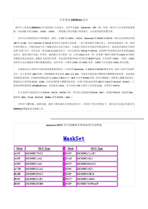
汽车常见EEPROM芯片就汽车上常见的EEPROM芯片按其接口方式来分,无外乎有I2C、Microwire、SPI三种,但每一种芯片又分为各种容量规格,比如I2C中的24C01、24C02、24C04,一般尾数大的比尾数小的容量大,且有着直接的倍数关系。
其中汽车音响用的芯片种类最多、最杂,从I2C的24C01-24C16,Microwire的93C06到93C56,现在出的音响还用到SIP的25160,而且Mirowire的93C46系列还分为标准与非标准,二者主要体现在引脚分布上,其内部功能基本一致。
使用时须仔细区分,否则出现读写不了数据还误认为芯片损坏,主要是日本的汽车音响会用到这种芯片,欧美的音响基本不采用这种“非准”芯片。
另外还有一种S130和S220的芯片,它们分别对应93C46和93C56,在欧洲产的音响还会经常见到85C52的芯片,通常为贴片封装,外型比一般的贴片芯片要宽一些,它和24C02基本一样,但其第7脚的写保护和24C02的写保护引脚电位状态是反的,85C52是高电位有效。
在较老的奔驰音响还可常见到BAW574252,它也是和24C01一样的,24C01有的芯片会出现能读不能写数据的情况,这时可用一片新的24C01或24C02代替。
24C02可完全兼容24C01所有功能。
在液晶仪表上用的芯片相对来说就要规范得多,大多采用Microwire,从93C46到93C86都有采用,基本上没有“非标准”芯片,且大多采用16bit结构,读取数据时须注意是16bit还是8bit,否则会出现高低位颠倒甚至数据错误的结果,这是调表须特别注意的事。
在新款的奔驰也常见24C04和B58芯片,B58可以用93C66代替。
但读写数据时,须把第七脚置为低电位。
稍老的宝马常用到CS56、CS66,它们也须把第七脚置为低电位。
在国产的仪表还用到SPI的25010和X25043(X5043),上海别克和时超用的A TMEL68343A,其实就是25010。
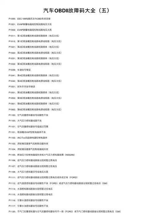
汽车OBDII故障码⼤全(五)P1000;EEC-VM电脑⽆法与OBD系统连接P1001;EVAP碳罐电磁阀控制线路电压太低P1002;EVAP碳罐电磁阀控制线路电压太⾼P1011;第1缸喷油嘴控制线路短路搭铁(电压太低)P1012;第1缸喷油嘴控制线路电源线短路(电压太低)P1021;第2缸喷油嘴控制线路短路搭铁(电压太低)P1022;第2缸喷油嘴控制线路电源线短路(电压太低)P1031;第3缸喷油嘴控制线路短路搭铁(电压太低)P1032;第3缸喷油嘴控制线路电源线短路(电压太低)P1039;车速信号错误P1041;第4缸喷油嘴控制线路短路搭铁(电压太低)P1042;第4缸喷油嘴控制线路电源线短路(电压太低)P1051;刹车开关信号错误P1051;第5缸喷油嘴控制线路短路搭铁(电压太低)P1052;第5缸喷油嘴控制线路电源线短路(电压太低)P1061;第6缸喷油嘴控制线路短路搭铁(电压太低)P1062;第6缸喷油嘴控制线路电源线短路(电压太低)P1100;空⽓流量感知器信号间歇性不良P1100;⼤⽓压⼒感知器线路不良P1101;空⽓流量感知器信号值超过范围P1101;喷油嘴/EVAP控制电晶体不良P1102;IAC/Tcc风扇继电器控制电晶体P1103;涡轮增压器排⽓控制致动器失效P1104;涡轮增压器排⽓控制电磁阀失效P1105;燃油压⼒控制电磁阀失效或⼤⽓压⼒感知器故障(NISSAN)P1106;进⽓压⼒感知器线路曾出现短暂过⾼电压P1107;进⽓压⼒感知器线路曾出现短暂过低电压P1108;⼤⽓压⼒感知器讯号线电压太⾼P1111;进⽓压⼒感知器线路曾出现短暂过⾼电压或系统正常(FORD)P1112;进⽓温度感知器信号间歇性不良(FORD)或进⽓压⼒感知器线路曾出现短暂过低电压(GM)P1114;⽔温感知器线路曾出现短暂过低电压P1115;⽔温感知器线路曾出现短暂过⾼电压P1116;引擎⽔温感知器信号间歇性不良P1117;引擎⽔浊感知器信号间歇性不良P1120;节⽓门位置感知器与空⽓流量感知器信号不⼀致(FORD)或节⽓门感知器线路曾出现短暂过⾼电压(GM)P1122;节⽓门感知器线路曾出现短暂过低电压P1124;节⽓门位置感知器信号测试错误P1125;节⽓门位置感知器信号间歇性不良或辅助节⽓门感知器系统线路操作不良(GM)P1127;在作KOER测试时,加热式含氧感知器没作⽤P1128;加热式含氧感知器信号交换P1129;加热式含氧感知器信号交换P1130;触媒前含氧感知器线路不良,燃料回馈控制系统正常(B1)P1132;触媒前含氧感知器线路不良,且感知器讯号指⽰浓度混合⽐(B1)P1133;含氧感知器(包括热线式含氧感知器)线路或感知本⾝不良或电压值超过电脑设定值P1134;含氧感知器(包括热线式含氧感知器)线路或感知本⾝不良或电压值超过电脑设定值P1135;点⽕开关讯号间歇性不良或电压值不正确P1137;触媒后含氧感知器线路不良,感知器讯号指⽰稀混合⽐(B1)P1138;触媒后含氧感知器线路不良,且感知器讯号指⽰浓混合⽐(B1)P1150;触媒后含氧感知器线路不良,但燃料回馈控制系统正常(B2)P1151;触媒后含氧感知器线路不良,且感知器讯号指⽰稀混合⽐(B2)P1152;触媒后含氧感知器线路不良,且感知器讯号指⽰浓混合⽐(B2)P1157;触媒后含氧感知器线路不良,且感知器讯号指⽰浓混合⽐(B2)P1158;触媒后含氧感知器线路不良,且感知器讯号指⽰浓混合⽐(B2)P1162;主含氧感知线路不良P1163;主含氧感知器电压变化过慢P1164;主含氧感知器不良P1165;主含氧感知器不良P1167;主含氧感知器加热不良P1168;主含氧感知器LABEL输⼊过低P1169;主含氧感知器LABEL输⼊过⾼P1170;混合⽐太浓/太稀/漏⽓/漏油或加热式含氧感知器输出电压⽆变化(FORD)P1171;加速增浓时混合⽐太稀P1172;空⽓流量计讯号电压值不正确,以致于混合⽐调整太稀P1173;空⽓流量计讯号电压值不正确,以致于混合⽐调整太浓P1187;机油温度感知器线路电压太低P1188;机油温度感知器线路电压太⾼P1195;⼤⽓压⼒感知器线路不良(信号从EGR感知器传出)P1196;起动开关线路不良P1200;喷油泵浦继电器线路不良P1200;喷油嘴控制线路不良。
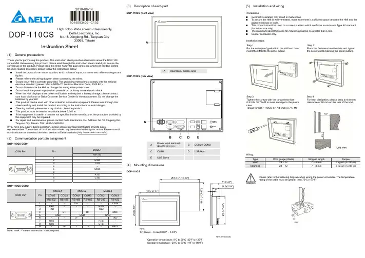
DOP -110CSHigh color ‧Wide screen ‧User-friendlyDelta Electronics, Inc.No.18, Xinglong Rd., Taoyuan City33068, TaiwanInstruction Sheet(1) General precautionsThank you for purchasing this product. This instruction sheet provides information about the DOP-100 series HMI. Before using this product, please read through this instruction sheet carefully to ensure the correct use of the product. Please keep this sheet handy for quick reference whenever needed. Before finishing reading this sheet, please follow the instructions below: ⏹ Install the product in an indoor location, which is free of vapor, corrosive and inflammable gas and liquids.⏹ Please refer to the wiring diagram when connecting the wires.⏹ Ensure your HMI is correctly grounded. The grounding method must comply with the national electrical standard (please refer to NFPA 70: National Electrical Code, 2005 Ed.). ⏹ Do not disassemble the HMI or change the wiring when power is on.⏹ Do not touch the power supply when power is on, or it may cause electric shock.⏹ When the HMI displays a low power notification and requires a battery change, please contact your local distributor or Delta Customer Service Center for the replacement. Do not change the batteries by yourself.⏹ This product can be used with other industrial automation equipment. Please read through this sheet carefully and install the product according to the instructions to avoid danger. ⏹ Cleaning method: please use a dry cloth to clean the product. ⏹ This product must be used at an altitude below 2,000 m.⏹ If the equipment is used in a manner not specified by the manufacturer, the protection provided by the equipment may be impaired.⏹For repair and maintenance, please contact Delta Electronics, Inc. Address: No.18, Xinglong Rd., Taoyuan City, Taiwan. TEL: +886-3-3626301.If you have any inquiry during operation, please contact our local distributors or Delta salesrepresentatives. The content of this instruction sheet may be revised without prior notice. Please consult our distributors or download the latest version at Delta’s website (/ia).(2) Communication port pin assignmentDOP-110CS COM1COM PortPin MODE1 RS-2321 -2 RXD3 TXD4 -5 GND6 -7 RTS 8CTS 9-DOP-110CS COM2COM PortPinMODE1MODE2 MODE3 COM2COM3COM2COM3COM2COM3RS-232 RS-485RS-485 RS-485RS-232 RS-4221 - - D+ - -TXD+ 2 RXD - - - RXD - 3 TXD - - - TXD - 4 -D+- D+ -RXD+5 GND GND GND6 - - D- - -TXD- 7 RTS - - - RTS- 8 CTS - - - CTS - 9- D- - D- - RXD-Note: mark “-” means connection is not required.(3) Description of each partDOP-110CS (front view)A Operation / display areaDOP-110CS (rear view)A Power input terminal (24AWG wire min.)B COM2 / COM3C COM1D USB HostEUSB Slave(4) Mounting dimensionsDOP-110CSUnit: mm (inch)Operation temperature: 0o C to 50o C (32o F to 122o F)Storage temperature: -20o C to 60o C (-4o F to 140o F)(5) Installation and wiringPrecautions: ⏹ Incorrect installation may result in malfunction.⏹ To ensure the HMI is well ventilated, make sure there is sufficient space between the HMI and the adjacent objects or walls.⏹ This product should be used on a case / platform which conforms to enclosure Type 4X standard (for indoor use only).⏹ The maximum panel thickness for mounting must be no greater than 5 mm. ⏹Copper conductor only.Installation steps:Step 1:Put the waterproof gasket into the HMI and then insert the HMI into the panel cutout.Step 2:Place the fasteners into the slots and tighten the screws until reaching the panel cutouts.Step 3:Tighten the screws with the torque less than 0.5 N-M / 0.7 N-M to avoid damage to the plastic case.Torque for DOP-110CS: 6.17 lb-inch (0.7 N-M)Step 4:For heat dissipation, please keep a minimum clearance of 60 mm on the rear of the HMI.Wiring:Type Wire gauge (AWG)Stripped length TorqueSolid 24 – 12 7 – 8 mm 5 kg-cm (4.3 lb-in) Stranded 24 – 127 – 8 mm5 kg-cm (4.3 lb-in)Please refer to the following diagram when wiring the power connector. The temperature rating of the cable must be greater than 75o C (167o F).(6) Hardware specificationsModel DOP-110CSDisplayPanel type 10.1" TFT LCD (65535 colors)Resolution 1024 x 600 pixelsBacklightLED Back Light(half-life under room temperature 25o C > 20,000 hours)*1 Displayrange226 mm x 128.7 mmBrightness 300 cd / m² (Typ.)CPU ARM Cortex-A8 (800 MHz)Flash ROM 256 MbytesRAM 256 MbytesTouchscreen 4-wire resistive touchscreen > 1,000,000 operated Buzzer Multi-tone Frequency (2K - 4K Hz) / 80dB Network interface N/AUSB 1 USB Slave Ver. 2.0; 1 USB Host Ver. 2.0SD N/ASerial communicationport COM1 RS-232 (supporting flow control)*2 COM2 RS-232 (supporting flow control) / RS485*2 COM3 RS-422 / RS-485*2Auxiliary function key N/A Calendar Built-in Cooling method Natural coolingApprovals CE / UL (please use shielding network cable and magnetic ring withthe filter of 300 ohm / 100 MHz)Panel waterproof level IP65 / NEMA4 / UL TYPE 4X (indoor use only)Operation voltage*2DC +24V (-15% to +15%) (please use an isolated power supply) Supplied by Class 2 or SELV circuit (isolated from MAINS by double insulation)Leakage current 500 V AC for 1 minute (between DC24V terminal and FG terminal) Power consumption*210.4 W (Max) *3Backup battery 3V lithium battery CR2032 × 1Backup battery lifeAbout 3 years or more at 25o C (subject to operation temperature and condition)Operation temperature 0o C to 50o C (32o F to 122o F) Storage temperature -20o C to +60o C (-4o F to 140o F)Operating environment 10% to 90% RH [0o C - 40o C], 10% to 55% RH [41o C - 50o C];pollution degree: 2Vibration resistance Conforms to IEC61131-2: continuous vibration 5 Hz - 8.3 Hz with amplitude 3.5 mm; 8.3 Hz - 150 Hz with amplitude 1GShock resistanceConforms to IEC60068-2-27:11 ms, 15 G Peak, in X, Y, Z directions each for 6 timesDimension(W) x (H) x (D) mm272 x 200 x 61Mounting dimension(W) x (H) mm261.3 x 189.3Weight Approx. 1330 gNote:1. The half-life of the backlight is defined as the maximum luminance being reduced by 50% when themaximum drive current is supplied to the HMI. The life of LED backlight shown here is estimated at the room temperature of 25o C with ambient humidity.2. The withstand voltage of the isolated power circuit is 1500V peak for 1 minute.3. The HMI power consumption is the power consumed when the HMI is not connecting with otherperipheral devices. To ensure normal operation of the HMI, the recommended capacity of the power supply is 1.5 to 2 times of the specified power consumption.4. Isolated power supply is recommended.5. For the DOPSoft programming software of the DOP-100 series and the user manual, you candownload them at /ia.6. DOP-100 series can be used with other industrial automation equipment. Please read through thissheet carefully and install the product according to the instructions to avoid danger.DOP -110CSYüksek Renk ‧ Geniş Ekran ‧ Kullanıcı Dostu HMIÜrünleriNo.18, Xinglong Rd., Taoyuan City 33068, TaiwanBilgi Dokümanı(1) ÖnsözBu ürünü satın aldığınız için teşekkür ederiz. Bu bilgi dokümanı DOP-100 serileri için bilgiler sağlar. Ürünü kullanmadan önce, doğru şekilde kullanım sağlamak için lütfen dokümanı tamamen okuyunuz. Ayrıca daha sonra ihtiyaç duyulduğunda kullanabilmek için bu dokümanı iyi muhafaza ediniz. Bu dokümanı okumayı bitirdikten sonra lütfen aşağıda yazılı olan talimatları uygulayınız.⏹ Ürünün kurulumunu aşındırıcı, yanıcı gaz veya sıvılardan uzak, temiz ve kuru yerlere yapınız.Sadece iç mekânda kullanınız⏹ Tüm bağlantıların dokümanda belirtildiği gibi olduğuna emin olunuz.⏹ HMI toprak bağlantısının doğru olduğuna emin olunuz. Topraklama metodu uluslararası elektrikstandardına uyumlu olmalıdır (NFPA 70: National Electrical Code, 2005 Ed). ⏹ Ürün enerjili iken HMI’ı sökmeyiniz ve bağlantılara müdahale etmeyiniz.⏹ Çalışma sırasında güç kaynağına dokunmayınız. Aksi halde elektrik çarpması meydana gelebilir. ⏹ HMI düşük pil uyarısı gösterirse ve pil değişimi gerekirse lütfen firmamız ile temasa geçiniz,kendiniz değiştirmeyiniz.⏹ DOP-100 serisi endüstriyel otomasyon ekipmanı olarak kullanılır. Lütfen bu dokümanı dikkatliokuyun ve tehlikeli durumları önlemek için ürünü belirtilen direktiflere uygun kurunuz. ⏹ Temizleme metodu: Ürünü temizlemek için kuru bir bez kullanınız. ⏹ Ürün 2000m altında bir rakımda kullanılmalıdır.⏹ Eğer ürün imalatçı tarafından belirtilmeyen bir şekilde kullanılıyorsa, ürün tarafından sağlanankoruma bozulabilir.⏹ Ürünle ilgili sorularınız için firmamız ile kontak kurabilirsiniz.Ürünün kullanımı ile ilgili sorularınız için teknik servisimizle kontak kurabilirsiniz. Bu bilgi dokümanının içeriği herhangi bir bildirime gerek duyulmadan değiştirilebilir. Dokümanın son versiyonunu internetten indirebilirsiniz. /ia .(2) Haberleşme PinleriDOP-110CS COM1 portCOM PortPin MOD 1 RS-2321 -2 RXD3 TXD4 -5 GND6 -7 RTS 8CTS 9-DOP-110CS COM2 portCOM PortPin MOD 1MOD 2 MOD 3COM2COM3COM2COM3COM2 COM3RS-232 RS-485RS-485 RS-485RS-232 RS-4221 - - D+ - -TXD+ 2 RXD - - - RXD - 3 TXD - - - TXD - 4 - D+- D+ -RXD+5 GND GND GND6 - - D- - - TXD-7 RTS - - - RTS -8 CTS- - - CTS - 9- D- - D- - RXD-Not: “-“ olarak yazılan pinlere bağlantı yapılmaz.(3) Parça AçıklamalarıDOP-110CS (Ön Görünüm)ADokunmatik Ekran / DisplayDOP-110CS (Arka Görünüm)A Güç Giriş Soketi(24AWG kablo min.)B COM2 / COM3C COM1D USB Host EUSB Slave(4) Montaj ÖlçüleriDOP-110CSÇalışma Sıcaklığı: 0o C ~ 50o C (32o F ~ 122o F)Birim: mm (inç)Depolama Sıcaklığı: -20o C ~ 60o C (-4o F ~ 140o F)(5) Montaj ve KablolamaÖnlemler: ⏹ Yanlış kurulum arızalara sebep olabilir.⏹ HMI’ın iyi havalandırıldığından emin olmak için, HMI ile yakın objeler veya duvarlar arasında yeterli boşluk olduğundan emin olun.⏹ Bu ürün, 4X standartına uygun bir kasa / platform (sadece kapalı alanda kullanım) üzerinde kullanılmalıdır.⏹ Montaj için kullanılan panelin kalınlığı 5 mm’den az olmalıdır. ⏹Sadece bakır kondansatör.Montaj için kullanılan panelin kalınlığı 5 mm’den az olmalıdır. Adım 1:HMI içine su geçirmez contanın takıldığına emin olunuz ve sonra pano boşluğuna yerleştiriniz.Adım 2:Montaj aparatlarını HMI’ın yuvalarınayerleştiriniz ve sonra panoya değene kadar vidaları sıkınız.Adım 3:Plastik kasaya zarar vermemek için vidayı 0.5 N-M’den fazla 0.7 N-M’den az tork ile sıkınız. DOP-110CS Tork: 6.17 lb-inç (0.7N-M)Adım 4:Isı dağılımı sağlanabilmesi için HMI arka paneli ile duvar, kurulum yüzeyi veya başka kontrol cihazı ile arasında en ez 60 mm boşluk bırakınız.Kablolama: Tip Kablo Ölçüsü (AWG)Soyma UzunluğuTork Tek Damarlı 24 - 12 7 - 8 mm 5 kg-cm (4.3 lb-in) Çok Damarlı 24 - 127 - 8 mm5 kg-cm (4.3 lb-in)Besleme konektörü bağlantısının aşağıdaki şekilde gösterildiği gibi yapıldığına emin olunuz. Kablo sıcaklık dayanım derecesi 75o C (167o F)’den yüksek olmalıdır.(6) Donanımsal ÖzelliklerModel DOP-110CSEkranPanel Tipi 10.1" TFT LCD (65535 Renk)Çözünürlük 1024 x 600 PikselAydınlatma LED Aydınlatma (Yarım ömürde 25o C’de 20,000 saatten az) *1 Ekran Ölçüsü 226 mm x 128.7 mmParlaklık 300 cd / m² (Tipik)CPU ARM Cortex-A8 (800 MHz)Flash ROM 256 MbytesRAM 256 MbytesDokunmatik 4 kablolu Rezistif Dokunmatik Ekran > 10,000,000 dokunma Buzzer Multi-tone Frequency (2K - 4K Hz) / 80dB Ethernet Arabirimi YokUSB 1 USB Slave Ver. 2.0; 1 USB Host Ver. 2.0SD YokSeri HaberleşmePortu COM1 RS-232 (Flow Kontrol Destekler)*2 COM2 RS-232 (Flow Kontrol Destekler) / RS485*2 COM3 RS-422 / RS-485*2Fonksiyon Tuşları Yok Takvim DâhiliSoğutma Metodu Doğal SoğutmaSertifikalar CE / UL (Lütfen ekranlı Ethernet kablosu ve 300 ohm/100 MHz filtreile manyetik halka kullanınız)Su Geçirmezlik Seviyesi IP65 / NEMA4 / UL Tip 4X (Bina içi kullanım içindir)Çalışma Voltajı *2DC +24V (-15% ~ +15%) (Lütfen dâhili filtreli güç kaynağı kullanınız.) SELV ile beslenir. (Şebeke hattından çift yalıtım ile izole edilmiştir)Kaçak Akım Dayanımı 1 dakika için 500 V AC (DC24V terminal ve FG terminalleri arası) Güç Tüketimi *210.4 W (Maks) *3Yedekleme Pili 3V lityum pil CR2032 × 1Yedekleme Pil Ömrü Normal koşullarda 25o C’de 3 yıl veya daha fazla.Çalışma Sıcaklığı 0o C ~ 50o C (32o F ~ 122o F)Depolama Sıcaklığı -20o C ~ +60o C (-4o F ~ 140o F)Çalışma Ortamı 10% ~ 90% RH [0o C - 40o C], 10% ~ 55% RH [41o C - 50o C];Kirlenme Derecesi: 2Titreşim Direnci IEC61131-2 ile uyumlu; Sürekli: 5 Hz ~ 8.3 Hz 3.5 mm, 8.3 Hz ~ 150Hz 1 GŞok Direnci IEC60068-2-27 ile uyumlu: 11 ms, 15 G Pik, X, Y, Z yönünde 6 kereÖlçüleri(G) x (Y) x (D) mm272 x 200 x 61Kesim Ölçüleri(G) x (Y) mm261.3 x 189.3Ağırlık Yaklaşık. 1330 gNot:1. Arka ışık yarı-ömrü maksimum besleme akımı HMI'ya uygulandığında orijinal parlaklığın %50oranında azaltılmış olması olarak tanımlanır. Burada gösterilen LED aydınlatma ömrü 25o C normal sıcaklık ve nem koşullarında tahmini bir değerdir.2. İzoleli güç devresi dayanma voltajı 1 dakika için 1500 V pik.3. HMI güç tüketimi herhangi bir cihaza bağlı değil iken tükettiği güçtür. Normal çalışma için tavsiyeedilen güç kaynağı tüketilen gücün 1.5 ~ 2 katıdır.4. İzoleli güç kaynağı kullanılması tavsiye edilir.5. DOP-100 serisi ürünlerin program editörü olan DOPSoft programı ve kullanıcı manuel’i websayfamızdan indirilebilirsiniz. /ia.6. DOP-100 serisi endüstriyel otomasyon donanımı olarak kullanılabilir. Tehlikeleri önlemek için bu bilgidokümanını dikkatlice okuyun ve belirtilen direktiflere göre kurulumu gerçekleştirin.DOP -110CS高彩‧寬螢幕‧友善人機介面Delta Electronics, Inc,No.18, Xinglong Rd., Taoyuan City33068, Taiwan安裝說明(1) ⼀般注意事項感謝您使用本產品,本人機介面安裝說明書提供DOP-100系列人機介面的相關資訊。
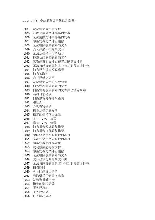
mcafee8.5i全部报警提示代码及意思:1024 发现感染病毒的文件1025 已成功清除文件感染的病毒1026 无法清除文件中感染的病毒1027 感染病毒的文件已删除1028 无法删除感染病毒的文件1029 要从扫描中排除的文件1030 无法从扫描中排除项目1031 拒绝访问感染病毒的文件1032 感染病毒的文件已被移到隔离文件夹1033 无法将感染病毒的文件移动到隔离文件夹1034 扫描已完成未发现病毒1035 扫描被取消1036 内存已感染病毒1037 发现感染病毒的引导记录1038 扫描发现感染病毒的文件1039 扫描发现感染病毒的文件并已清除病毒1040 活动日志错误1041 扫描报告内存分配错误1042 路径太长1043 介质有写保护1044 找不到指定的介质1045 指定的扫描项目无效1046 文件 I/O 错误1047 磁盘 I/O 错误1048 扫描报告常规系统错误1049 扫描报告内部系统错误1050 无法修复受密码保护的项目1051 无法扫描受密码保护的项目1052 感染病毒的捆绑对象1053 发现感染病毒的文件1054 感染病毒的文件已删除1055 无法删除感染病毒的文件1056 文件已移动到隔离文件夹1057 无法将感染病毒的文件移动到隔离文件夹1059 扫描超时1060 引导区病毒已清除1061 清除引导区病毒时出错1062 发送警报时出错1063 指定的选项无效1064 服务已启动1065 服务已结束1066 任务成功启动1067 无法启动计划的任务1068 计划的任务已停止1069 停止计划的任务时出错1070 任务成功完成1071 任务已取消1076 记录信息时出错1077 内存分配错误1086 扫描进程错误1087 按访问扫描已启动1088 按访问扫描已停止1089 扫描设置1090 OAS 已停止1091 已阻止脚本运行1092 已被行为阻挡规则阻挡1093 已被缓冲区溢出保护阻挡1094 已被端口阻挡规则阻挡1095 将被行为阻挡规则阻挡1099 将被缓冲区溢出保护阻挡1100 在文件中检测到宏1101 已从文件中删除宏1118 更新成功完成1119 更新失败:请参阅事件日志1120 正在更新1121 更新已取消1122 正在升级1123 升级失败,参阅事件日志1124 升级已取消1125 DAT 版本不够新1126 扫描任务被 DAT 文件的自动更新而取消1127 OAS 扫描引擎已禁用1128 扫描超时1129 扫描任务被 WINDOWS 关闭1200 进程已启动1201 进程已结束1202 按需扫描已启动1203 按需扫描完成1204 报告操作系统序列号1270 病毒已隔离,没有清除程序1271 病毒已隔离,启发式扫描1272 病毒已隔离,不能清除1273 病毒已隔离,已加密1274 病毒未清除或隔离1275 病毒,启发式扫描,隔离失败1276 病毒,清除错误,隔离失败1277 病毒,已加密,隔离失败1278 病毒,没有清除程序,已删除1279 病毒,启发式扫描,没有清除程序,已删除1280 病毒,清除错误,已删除1281 病毒,已加密,已删除1282 病毒,没有清除程序,删除失败1283 病毒,启发式扫描,删除失败1284 病毒,清除错误,删除失败1285 病毒,已加密,删除失败1286 病毒,没有清除程序,已继续1287 病毒,启发式扫描,已继续1288 病毒,清除错误,已继续1289 病毒,已加密,已继续1290 病毒,没有清除程序,拒绝访问1291 病毒,启发式扫描,拒绝访问1292 病毒,清除错误,已拒绝访问1293 病毒,隔离失败,已删除1294 病毒,隔离失败,删除失败1295 病毒,隔离失败,已继续1296 病毒,隔离失败,已拒绝访问1297 病毒,删除失败,已隔离1298 病毒,删除失败,隔离失败1299 病毒,删除失败,已继续1300 病毒,删除失败,已拒绝访问1401 用户检测1402 用户清除和移动失败1403 用户检测已移动1404 用户清除和删除失败1405 用户检测已删除1406 用户检测已移动1407 用户移动和删除失败1408 用户检测已删除1409 用户检测移动失败1410 用户检测已删除1411 用户删除和移动失败1412 用户检测已移动1413 用户检测删除失败1500 已清除电子邮件感染的病毒1501 感染病毒的电子邮件已隔离1502 无法清除邮件中感染的病毒1503 检测到感染病毒的电子邮件1504 感染病毒的邮件项目已删除1505 电子邮件内容已过滤1506 电子邮件内容已阻挡1507 入站邮件因磁盘空间不足而挂起1508 入站邮件已恢复1509 启动请求处理成功1510 关闭请求处理成功1511 警告 - 异常终止1512 出现最大负载的情况1513 邮件病毒已隔离和清除1514 邮件病毒已隔离[未清除]1700 服务已成功启动1701 服务已成功结束1702 文件已阻挡1703 发现感染病毒的邮件正文1704 邮件被主题行扫描阻挡1705 发现感染病毒的文件1712 出现内部错误1713 按需扫描已启动1714 按需扫描已完成1715 防病毒引擎已停止1716 防病毒引擎已启动1719 无更新可用1721 磁盘空间不足1722 发现感染病毒的文件1725 产品即将达到使用寿命1726 引擎即将达到使用寿命1727 产品已超过支持期限1728 引擎已超过支持期限1729 已超过产品使用寿命1730 已超过引擎使用寿命1800 任务已成功启动1801 启动任务时出错1802 任务已完成1803 停止任务时出错1804 已发现并清除文件病毒1805 感染病毒的文件已成功隔离1806 感染病毒的文件已删除1807 感染病毒的文件已忽略。

DIGI*TRACD T A001-0901DIGI*TRAC Annunciator Guide iiDTA001-0901, September, 2001Copyright © 2001 Hirsch Electronics Corporation. All rights reserved. S cramblePad ® is a registered mark of Hirsch Electronics Corporation. DIGI*TRAC™, MATCH™, S cramblePad, S crambleProx ® and SCRAMBLE*NET™ (abbreviated S*NET) are all trademarks of Hirsch Electronics Corporation.Hirsch Electronics Corporation1900 East Carnegie AvenueBuilding BSanta Ana, CA 92705-5520Phone:949-250-8888 or 888-809-8880Fax:949-250-7372Web:DTA001-0901Getting HelpIf you encounter a problem that is not discussed in this guide and youneed technical support, do the following:1.Contact your local dealer or the provider of this product.2.If your dealer is not available, contact Hirsch Technical Supportdirectly. This can be done in a number of ways:M a il il::Hirsch Electronics Corporation1900 East Carnegie AvenueBuilding BSanta Ana, CA 92705-5520Attn: Technical ServicesV o i c e:(877) HIRSCHX (technical queue)(888) 809-8880F a x:(949) 250-7362E m a il il: : :*****************************W W W:Whenever you call your local dealer or Hirsch, be sure to have yourregistration material, serial number and software version numberavailable.For future reference, record these numbers here.Serial Number: _________________________________Version Number: ________________________________Dealer: ________________________________________Dealer Phone #: ________________________________CCM Rev/Version #: _____________________________Getting Help iiiDIGI*TRAC Annunciator Guideiv Getting HelpDTA001-09011IntroductionThe DIGI*TRAC Annunciator (DTA) is used to monitor basic security functions—such as alarm, input, and relay status. It provides a local display of critical information near or outside the protected area.On the back of the Annunciator is an integrated MATCH2 board that communicates with the controller using the same digital channel as both the ScramblePad and MATCH.F i g u r e e 11: : D D IG I *T R A C C A A n n un unc c i a t o r r – – – S S i d e e V V i e wThe front of the Annunciator includes both a four-line, 20-character non-backlit LCD display and four status request buttons.The status request buttons are smart keys that change their meaning according to the current dialog displayed on the LCD screen abovethe keys.IntegratedMATCH-2DIGI*TRAC Annunciator User’s Guide 2Both a picture and an illustration of this front panel is shown in Figure 2:F i g u r e e 22: : D D IG I *T R A C C A A n n un unc c i a t o r r – – – F F r on ont t t V V i e wThese keys are used for status requests only and cannot issue commands of any sort.Status requests supported are:OAlarm Log Display from the Controller's Alarm Buffer (holds last 256 alarms)OCurrent Relay Status (to determine whether a door is locked)O Current Input Status (to determine where a door is closed or adevice is secured)This unit requires CCM 7.0 but does not require any host software for setup or operation. It is ideal for lobbies and other passages outside of the secured area where an individual can confirm that theprotected area is secure (such as locked and ready to leave).4-line LCD screen4-button keyboardDTA001-0901Installing the AnnunciatorThe DIGI*TRAC Annunciator comes pre-assembled with the MATCH2installed on the back of the DTA. There are several optional coverplates available as well as surface mount and flush mount backboxes.The DTA is a secure annunciator and requires a ScramblePad code orcard to activate the display.A simplified example of an Annunciator installation looks like Figure 3:F i g u r e e 33: : T T y p i c a l l A A n n u n c i a t o r r I I n s t a l l a t i o n3DIGI*TRAC Annunciator User’s Guide 4 A more complex example is shown in Figure 4:F i g u r e e 44: : A A n n un unc c i a t o r r E E x a m p l eThis example represents the way in which an annunciator can be used to monitor activity within a given area—in this case, three rooms incorporating readers, keypads, relays, motion detectors, amongst other devices—and supply alarm and event information specific to the entry and exit of personnel to/from that area.The required components include:ODIGI*TRAC Controller OAnnunciator O Keypad or Card ReaderMost of the installation and configuration requirements for theAnnunciator are identical to those you would observe for the MATCH2 board (refer to “MATCH Interface Installation” on page 7-74 in the DIGI*TRAC Design and Installation Guidefor more details).DTA001-09015T o install the Annunciator:1.Locate the place where you want to put the DTA. This should belocated near the ScramblePad/ScrambleProx and/or reader that will authorize the DTA’s use.e the selected surface mount plate or flush mount back box to position and draw an outline on the wall.3.Either secure the surface mount box to the wall or cut a hole for the flush mount box, then route the appropriate wires into the box.4.T urn off the power to the area or wall where you want to install the Annunciator.5.Depending on the type of device you are using, connect the device in one of these ways.If you are using a ScramblePad to activate the Annunciator :a.Route the wire from the Controller to the D*TRAC port on the DTA’s MATCH board as shown in Figure 5. Connect the wire to the port.F i g u r e e 55: : C C on onn n e c t t C C on ont t r o ll lle e r r a a n d d K K e y p a d d t t o o t t h e e A A n n u n c i a t o rThe DTA communicates with the MATCH2 via its RS-232 port (P2) and draws its power from one of the MATCH2's reader channels (C2). This comes pre-wired from the factory.Connecting a ScramblePad SCRAMBLEPAD Keypad Port D*TRAC PortDIGI*TRAC Controller Back of AnnunciatorDIGI*TRAC Annunciator User’s Guide 6 b.Connect an extension cable from the Keypad port on the DTA’s MATCH2 board.If you are connecting a reader to the Annunciator : a.Relocate the connector on Port 1 (P1) of the MATCH2 to Port2 (P2). This is only used as a power source for the DTA.b.Connect the Reader to Port 1 on the DTA’s MATCH2 board as shown in the example in Figure 6.F i g u r e e 66: : C C on onn n e c t i n g g R R e a d e r r t t o o t t h e e D D T AThis picture shows a specific type of proximity reader(CR20L) which is also used in the DS47L-SPX. Your reader and wiring specifications may differ from this picture.Connecting aReaderSOLDER &HEAT SHRINK ALL SPLICESCR20L-125-6005(HID# 6005)7If you are using a ScrambleProx as the keypad , follow these instructions (as shown in the example in Figure 7):a.Connect an extension cable from the Keypad port on the back of the ScrambleProx to the Keypad port on the DTA’s MATCH2 board.b.Relocate the connector on Port 1 of the MATCH2 to Port 2. This is only used as a power source for the DTA.c.Connect the DIGI*TRAC controller cable to the D*TRAC port on the DTA MATCH2 board.d.Disconnect the proximity reader connector from Port 1 on the ScrambleProx.e.If necessary, use an extension cable (Hirsch# MCRH) toconnect the loose reader cable from Port 1 on theScrambleProx to Port 1 on the MATCH2.Follow the connection chart shown in Figure 7.F i g u r e e 77: : C C on onn n e c t i n g g a a a S S c r a m b l e P r o x x t t o o a a a D D T AUsing aScrambleProxRoute keypad cable from theScrambleProx to the Keypad porton the DTA ➀from Port 1 on the ScrambleProx and connect it to Port 1 on the back of the DTA. If necessary , fabricate a cable for this purpose.6.If you are using a keypad, route the data wire from theScramblePad or ScrambleProx keypad to the Keypad port on theDTA’s MATCH2 board as shown in Figure 5.The ScramblePad or reader used to activate the DTA canalso be used as a standard entry access device. TheScrambleProx can be used as long as its integral readeris connected to the DTA’s Port 1 of the MA TCH2 instead ofPort 1 on the ScrambleProx as shipped from the factory.7.Follow the same power cable requirements as you would use toconnect an independent MATCH2. Ordinarily the controllerprovides sufficient power to operate attached ScramblePads andMATCH2 interfaces; however, there are conditions which requiremore power than the controller can supply.8.Secure the DTA to the box or plate.Once connected, the operator accesses the Annunciator by eitherentering a special code into the connected ScramblePad or using aspecial card on the attached reader or ScrambleProx. A simple menuappears on the Annunciator LED. The operator then follows the menuto access the information they require.8Assigning Annunciator PrivilegesThe process of enabling the DTA for the controller depends on thehost PC software used. There are three methods for assigningAnnunciator privileges to a user:O Keypad assignmentO SAM assignmentO Velocity assignmentEach of these methods is discussed in this section.Keypad AssignmentT o assign Annunciator privileges from a ScramblePad:1.From an attached ScramblePad, enter program mode.e the following command and syntax to assign Annunciatorprivileges to a user:44*1*User Number*Codewhere User Number is the number assigned to this user and theCode is the PIN number assigned to this user at this door toactivate the DTA.You can also use this command to assign Annunciator privilegesthrough the SAM diagnostics window or the MOMENTUM Hirsch T estT ool.SAM AssignmentT o assign Annunciator privileges using SAM:1.Access the Add/Edit User Group worksheet by selecting A A ddup in the Groups menu, or press F F3 3 A A d d.G r o up2.Select the User Group you want to enable for this function. TheAdd/Edit User Group dialog box appears.3.Either define a new group or select an existing user group.4.Click the “Function” field arrow. An option list appears.m C C onont t r o l button. A list of available alarm functions5.Select the A A l a r mappears.m C C a n c e l function.6.Select the A A l a r m9107.Select the access zone and the code extension you require to activate this DTA.F i g u r e e 88: : P P r o g r a mm mmi i n g g t t h e e C C o n t r o l l e r r U U s i n g g S S AM Select Alarm Cancel fromSelect the AccessZone you need forthis function Select the ID Form at and Code extension you want to activate the DTAthe Alarm Control optionlistVelocity AssignmentIf you are using Velocity, you can assign an operator the ability to usethe Annunciator in one of two ways:O Define a Function GroupO Define a user credential through Enrollment ManagerCreating a Function Group is the best way if you plan to assignAnnunciator privileges to more than one user.Function Group AssignmentT o assign Annunciator privileges for a group through Function Groups:1.From the Velocity system tree, select the Function Groups file. Alist of all currently-defined function groups and the Add NewFunction Group button appear in the right hand Componentspane.on G G r ououp p button to createdd N N e w w F F ununc c t i on2.Either double click the A A dda new function group, or double click an existing function group.The Function Group Properties dialog box appears.3.If this is a new function group, enter a new function group namein the Name field. If this is an existing function group, a namealready appears.dd.... button to add the required code extension to this4.Click the A A ddfunction group. The Define Extension dialog box appears.5.In the “Extension Digits” field, enter one or two digits.6.In the “Function Category” field, select A A l a r m from the pull-downoption list.m C C a n c e l from the pull-down7.From the “Function” field, select A A l a r moption list.8.From the “Controller” combo box, select the currently-definedcontroller to which this extension code applies.9.From the “Control Zone” combo box, select the currently-definedcontrol zone or master control zone during which this extensiondigit applies.dd to register the new extension digit in the lower window.10.Click A A dd11.Click O O K to return to the Function Group Properties dialog box.12.Click O O K to return to the main menu.11ing Function Groups in the Administrative Mode, assign thisfunction group to the specified user(s) on the Function property page.F i g u r e e 99: : A A s s i g n i n g g A A n nu nun n c i a t o r r P P r i v i l e g e s s u u s i n g g V V e l o c i t y ’s s F F u n c t i o n nG G r o up Click A A dd dd....Select A A l a r m &A l a r m m C C a n c e lClick O O KClick A A dd dd....Single Credential AssignmentT o assign Annunciator privileges for a single credential through Enrollment Manager:1.Open the Enrollment Manager.2.Select the person to whom Annunciator privileges should beassigned.dd N N e w3.Create a new credential by double clicking the A A ddC r e d e n t i a l button. The Credential Properties dialog box for theselected person appears.4.Fill out this form as required making sure to supply a code orcard.5.Click the Function tab.unc c t i o n radio button.6.If not already selected, click the S S i n g l e e F F un7.In the “Function Category” field, select A A l a r m from the pull-downoption list.m C C a n c e l from the pull-down 8.From the “Function” field, select A A l a r moption list.9.From the “Controller” combo box, select the currently-definedcontroller to which this extension code applies.10.From the “Control Zone” combo box, select the currently-definedcontrol zone or master control zone during which this extension digit applies.dd to register the new extension digit in the lower window.11.Click A A dd12.Click O O K to return to the Enrollment Manager main menu. Thenew credential appears in the Credential pane for the selected user.13.Click O O K to return to the main menu.1314F i g u r e e 110: : A A s s i g n i n g g A A n nu nun n c i a t o r r P P r i v i l e g e s s t t o o a a a C C r e d e n t i a l l u u s i n g g E E n r o l l m e n t t M M a n ag age er Click Function T abthen A A l a r m &A l a r m m C C a n c e lEnter code and/orcard15Operating the AnnunciatorThe following procedure shows you how to use the Annunciator.1.Go to the keypad (either ScramblePad or ScrambleProx) or cardreader connected to the DTA. This normally will be the keypad or reader mounted closest to the DTA.Whenever the DTA is not activated, it displays the time and day like this example:F i g u r e e 111: : I I n a c t i v a t e d d D D T A A S S c r ee een n2.Perform one of these procedures:•At the keypad, enter your special DTA-activation code. This is often a code extension (SAM) or function group (Velocity).•At a reader, swipe your special DTA-activation card.Your regular access code/card alone cannot activate the DTA. The code/card must be used with an extension digit or function group digits. The system administrator must issue you this special code/card or extension to activate the DTA.The DTA is activated. The DTA’s screen displays the initial screen like Figure 12.F i g u r e e 112: : A A n n un unc c i a t o r r M M a i n n M M e nuEND ALMLOG INP STAT RELAYSTAT16These options are:3.Press the button for the option you want.A list of the current alarms or status points (input or relay) for the connected controller appear.You will only see the alarms or status for the controllerconnected to this DTA. No other controller’s status is displayed.O If you press the ALM LOG button, a screen like Figure 13 appears:F i g u r e e 113: : A A l a r m m L L o g g M M e n uOnly one alarm at a time can be displayed.P r e s s s t t h i s b s button to utton to utton to::ENDEnd the current session and return the DTA to inactive mode.ALM LOGDisplay the log of all alarms experienced by this controller only.INP STATDisplay the current status for all inputs connected to this controller only.RELAY STATDisplay the current status for all relays(outputs) connected to this controller only.BACK FWD SAVEERASEO If you press INP STAT, a screen like Figure 14 appears:F i g u r e e 114: : I I n p u t t S S t a t u s s M M e nuThis screen displays the current Alarm Input or ExpansionAlarm Input status. The report is time stamped at the time thebutton is pushed. A list of abbreviations you will find on thisscreen are shown in the following table:A line fault of some sort, followed by a briefexplanation; in the preceding case, it indicates anopen circuit (‘open ckt’).* Designates an input or expansion input iscurrently in alarm (even if masked).AL Alarmunmasked.iscontactsecure... AlarmisContactisactive.RQ RQEcontactactive.contactTP T amperisM Masked by one of the following devices:Tz MaskedbyZone.TimeZone.byControlC MaskedUnlock.Ul Maskedbytimer.DelaybyEntry/ExitX Masked1718An example of several possible input status values are shown in Figure 15:F i g u r e e 115: : I I n p u t t S S t a t u s s E E x a m p l eO If you press RELAY STAT, a screen like Figure 16 appears:F i g u r e e 116: : R R e l a y y S S t a t u s s M M e nuA list of abbreviations used in this display are explained in the following table:R The relay designation followed by the number of this relay, such as R1 or R2.* Relay isenergized. The following abbreviations specify the current condition ofthe relay:D (on left) Door access in progress.U Unlock/Relock.C Control timer.N Control Force On.BACK FWD EXIT19An example of this screen appears in Figure 17:F i g u r e e 117: : R R e l a y y S S t a t u s s E E x a m p l eIn almost every case, the list of alarms, inputs, and/or outputs is longer than four lines.4.Press one of these keys:•Use the FWD key to move forward in the list.•Press the BACK key to move backward in the list.•Press the EXIT key to return to the main menu shown in Figure 12.F in 2nd group Control Force Off.A Actuate by Time Zone. D (in middle)Disable by Time Zone. ZControl Zone “Drive On” by Alarm Input or Expansion Alarm Input. F in 4th group Control Zone “Drive Off” by Alarm Inputor Expansion Alarm Input.L Lock Down.O Lock Open.. (period)Particular function is not currently active.•If this is Alarm Log, use the ERASE key to delete the alarmlog. All alarms are cleared from the buffer and a screen likethis appears.•If this is the Alarm Log, press SAVE to save the current alarmentries for later review.5.When you’re finished looking through a particular list, press theEXIT key to return to the main menu. Press the END key todeactivate the DTA.20Appendix: Wiring SpecificationsFor information on basic electrical wiring specifications, such as wiretypes and lengths used for connecting the DTA, refer to“ScramblePad/MATCH Inputs” on page 2-15 of the DIGI*TRACDesign and Installation Guide (Hirsch# MAN001).For information on powering a ScramblePad or MATCH locally, see“Powering ScramblePads/MATCH Interfaces Locally” on page 2-31 inthe DIGI*TRAC Design and Installation Guide.For additional information, refer to “Powering the ScramblePadLocally” on page 7-71 in the DIGI*TRAC Design and InstallationGuide for the best technique to use.2122。

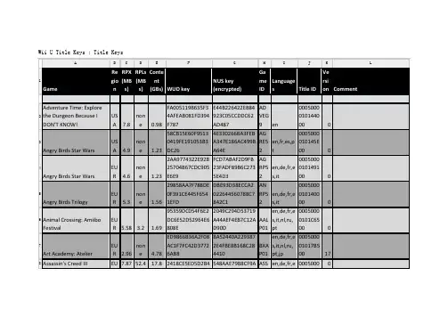
Wii U Title Keys : Title KeysA B C D E F G H I J K L1 Game RegionRPX(MBs)RPLs(MBs)Content(GBs) WUD keyNUS key(encrypted)GameIDLanguages Title IDVersion Comment2Adventure Time: Explorethe Dungeon Because IDON'T KNOW!USA 7.8none 0.98FA005119B635F34AFEAB081FD394F787E44B226422EB84923C05CCDDC62AD487ADVEG9 en0005000010144000 03Angry Birds Star Wars USA 4.9none 1.2358CB15E60F95130419FE191053B3DC264E330266BA3FEBA347E186AC499BA64EAGRE52en,fr,es,pt0005000010145E00 04Angry Birds Star Wars EUR 4.6none 1.232AA9774322E92B25704B67CDC905E6E9FCD7ABAF2D9FB23FADF89B6C2735E4D3AGRP52en,de,fr,es,it0005000010149100 05Angry Birds Trilogy EUR 5.3none 1.5629858AA7F788DE0F391CE445F6541EFDDBE93D38ECCA2022*********C7842C1ANRP52en,de,fr,es,it0005000010140000 06Animal Crossing: Amiibo Festival EUR 5.58 3.2 1.6995359DC054F6E2DC6E52D529E4E6808E2049C294D53719A44AEF4EB7C12AD90DAALP01en,de,fr,es,it,nl,ru,pt00050000101C6500 07Art Academy: Atelier EUR 2.96none 4.78ED9866B36A2F08AC1F7FC42D37726AB88A52440A2293872E4FBE8B168C284410BXAP01en,de,fr,es,it,nl,ru,pt,jp000500001017B500 178Assassin's Creed III EU7.87 52.4 17.8 2418CE5ED5D2B4548AAE79B8CF9A ASS en,de,fr,e00050000A B C D E F G H I J K LR 255F4538398DD50533 78C7F997ABB135D1C6P41 s,it,nl,ru,pt01010F6009Assassin's Creed IV: Black Flag EUR0.144 22.4 12.7BF9D4229CE4224160273ACA9A1AC9FC9A529987345AFF0AC4256C76AEA370A0AASBP41en,de,fr,es,it,ru,pt,jp0005000010138800 01Barbie Dreamhouse Party EUR 1.95none 2.679E9F15E7447E5291028BE7E90D7546B617D3DE2473C9E3727B43F236D9039ED7ABBPVZ0005000010147B00 01 1Batman: Arkham City -Armored EditionEUR 16.9none 12.2(wrong key inrelease package)ABTWR Wrong key12Batman: Arkham Origins USA15.81none 12.212B08C21C6BF82ABACBD55CE2D395E64150FE00E979A98F25F9E5AE06BA7BB440AZEEWR0005000010137C00 113 Bayonetta EUR0.004 8.09 11.716A566EC4C3B70C1C8CEB6161A03D584B9CAB6CA99E9BE8BE72CBD566B1BBBB8AAFD01en,de,fr,es,it0005000010157F00 114 Bayonetta USA0.004 8.09 11.7FD196BDA8F6C5D066A72AA5BBC47BFB613EFF83747B473730CC04393BE03B07FAAFE01en,de,fr,es,it0005000010157E00 115 Bayonetta 2 USA16.85none 14.433FBCA056FF816070156CB917A9F32E7D5BF0363083A2E2554D966BF3A0D0D5EAQUE01en,de,fr,es,it0005000010172600 016Ben 10: Omniverse EUR 3.3none 2.782BEC6548650FD19723DBAD0BFE30C235FABF6BD7D6F7DE2DFB0D1ABEPAFen,de,fr,es,it000500001011100A B C D E F G H I J K L6A89 F65E0C 0017Ben 10: Omniverse USA 3.14none 2.7F56A6AFF51D08844A9D5D7F41007FC057092878593502E59E62B3B75DE3DE8B4ABEEG9 en,fr,es000500001010AC00 018Ben 10: Omniverse 2 EUR 2.8none 1.890A3BB62D36D58BBC28BF0C35E6A21FA1E036DF624BFD34043E565EB8D20DA427ABVPAFen,de,fr,es,it0005000010146600 019Ben 10: Omniverse 2 USA 2.7none 1.882E45D889B86A79EE908E5A6D184A219177D9B179A2F20048BAFB65A336F8C583ABVEG9 en,fr,es0005000010147500 02Call of Duty: Ghosts EUR0.004 11.6 15.7DE1903D6F204CA6A3A2FE8BF656DA3B85E5167E3789ED873D4EB590FB332162FACPP520005000010156100 0 Title ID not on NUS21Call of Duty: Ghosts USA0.004 11.6 15.728512A78013B127E418F02A1F45EFB9928107EB9B621A317AAF1FE683FBC3C29ACPE520005000010146800 0 Title ID not on NUS2 2Captain Toad TreasureTrackerEUR 3.9none 1.19C253B04725C95C344AC158E7C5C93A484F72A299B800C62489A43E8FFF227E19AKBP01en,de,fr,es,it0005000010180700 02 3Captain Toad TreasureTrackerUSA 3.73none 1.18EC2EFF7E309ABC8510D5C023BD35061C2BA6B0DB191A15CF9ECD150CCBF2A02FAKBE01 en,fr,es0005000010180600 024Darksiders II EUR 49.5none 9.117C2CB2EB3B4309E3FCCC6E602B9D3BEF3FB2EF5B22E1B3A73FC4F806AD2P780005000010110F 1A B C D E F G H I J K L2946 60A4 002 5Deus Ex: HumanRevolution - Director's CutEUR 9.9none 15.150E694367E63233FECC76609E2229B65E28AB4923FB522A62F1B32B07C3BF13CADXPGD000500001012B200 026Devil's Third EUR 23.3none 13.392BEDF1789CC99D9D94FF7C8C99358C35128956B203EB4AD7FD97C77EA31ADECADNP010005000010177700 1627Disney Epic Mickey 2 USA 23.8 0.96 7.26C2E39E4146816F73BE0D03D7EA984AE2192A1CBAED3D29933D359EDC5A53D3BAEME4Q000500001010DB00 02 8Disney Infinity 2.0 MarvelSuper HeroesEUR 21.3none 11.2BE85341F2FA8A3A10ED79FC68AE1CA914CE3FEEB4C184D1E2DBE187B49837E93ADRP4Q0005000010188C00 02 9Disney Infinity 3.0: PlayWithout LimitsEUR25.23none 11.24C904F883338E3EF7A16A70DD863B97FFE0491A2AC86739E4EA28147C931DCB8ABD3P4Qen,de,fr,es,it,nl00050000101B3D00 03Disney Planes USA 3.3 3.7 2.147C93CB4C99EA5471108749B803EFDDAFFD5218D4C86CA8111925AD7780E720C1APAE4Q000500001011C500 03 1Donkey Kong Country:Tropical FreezeEUR 10.1none 10.51658AD6A6101B5E3B305693255F47A5D11CEE7F2EE6272974C530C4121A0191DARKP01en,de,fr,es,it0005000010138300 23 2Donkey Kong Country:Tropical FreezeUSA 10.1none 10.577F51431746983AEA501D1EACB8C18BE238CA2E039961FA32E453A4ARKE010005000010137F 2A B C D E F G H I J K LDAF54 15CC 0033DuckTales: Remastered USA 8.3none 0.7485DE1B56166D1C02975C6CD18D860E6EE082B97981FAC02CAD32C783BF16A555WDKE080005000010129000 034ESPN Sports Connection USA 9.0none 1.5231F987636FFE9DCD909CF6AB8615F9797DE26BBBA768735F75D7342D42FDD37CASPE41000500001010B400 03 5Family Party: 30 GreatGames Obstacle ArcadeUSA 1.38none 0.61D474D9D50A0B8EF985F1D70CF864F13FA37B75FD0DE03D2A297471477066C7CAFPEG9 en000500001010F300 03 6Fast and Furious:ShowdownEUR 10.6none 1.7884086A1950EA1BB4466B29383D40620376293F2A744FE809BC3BF1B8A50A67EFAF6P52000500001012DA00 0 Title ID not on NUS3 7Fast and Furious:ShowdownUSAE7211E4429E577AA5A1926BFD8D2AC165EB41C3D5B17BAFB66F4A117C864C434AF6E520005000010111600 0 Title ID not on NUS38FIFA 13 EUR 21.9none 7.89DDBBF08BEA0402434BD838BC001CFE0827B5DB268A3D3FFB6231D2AFCDAB058FAF3P69en,de,fr,es,it,nl,pt,ru000500001010EE00 039FIFA 13 USA4F2E852079006A2DBAA5A1B2FE495B534A0CE182BB53C237490A8553C2C39C5BAF3E69 en000500001010D900 040Game & Wario USA 11.2none 3.1694A029C585908E2EE50D1DD3125A096F20F1B44AAE4FB99A0FA3C15ASAE01 en000500001011F20A B C D E F G H I J K L37AD F622 0041Game Party Champions EUR 15.1none 1.5949B33D9232B5FC83851879D21FADBF5447092E88D6DD5AD2EBBAA4F3E6E4BF51AGPPWRen,de,fr,es,it,nl000500001010FF00 042Game Party Champions USA40A732A56B394B3B007E2ED98BB85363A908126B0FD052E71A63C5D7BC9E46CAAGPEWR000500001010E400 043Hello Kitty Kruisers USA 9.8 7.1 0.88C2E63131C945F410335FED95541020E279E6F438E06EE904DB42D33B11FF0B1AHKE990005000010147E00 14 4Hot Wheels: World's BestDriverUSA 13.6none 3.2734C3A3922EE522BDFFD96777E5F38B2BEA87266E5797A08FCD46C642AF33214BAHWEWR0005000010143300 14 5How To Train Your Dragon2EUR 2.2none 0.462F436867A48CCF48DE874D968A35452F34544A2A5C8E0D4D25EAD0BD38EFE0E7EATDPVZen,de,fr,es,it,nl,pt0005000010162A00 046Hyrule Warriors EUR 6.01none 6.882AA5EBB4CA3D84DAF571C851444FFDDE1B041837D5CA9B1CFB3ADE8EEED8665DBWPP01en,de,fr,es,it000500001017D900 047Hyrule Warriors USA485CB78A3A34CA6915BD2A4F645A52C43048E7AD2165405B08D8AAE736F5B7A1BWPE01000500001017D800 048Injustice: Gods Among Us EUR 15.5none 7.32C186F2EE3CE0E4ABF395846D3295D307374445B255DF4D292BD4903AJSPWen,de,fr,es,it,ru00050000101110A B C D E F G H I J K LE140 40A5F R A0049Just Dance 2014 USA17.14none 12.512432B8672C625CDA87A21CC2DB89A9712BD9030631398C67A3261C39A96D01DEAJ5E410005000010139900 15Just Dance 2015 EUR 21.0none 9.77A44BED3797CE08487560C37C437C9315B5EC6CBFEAF57679AFE5ED8CFF2539CBBJDP410005000010176F00 051Just Dance 2015 USA3279FD7CB316491385F964F71CCD6BB9E147ACEE483091CA43A483C59486F295BJDE410005000010179100 052Just Dance 2016 EUR14.68none 14.69BA3A06F9DAB9E0EE9B175ABF4A05E1B3A219F79958397B833F2D8AA11E9005C9AJ6P4100050000101B9800 053Just Dance 4 USA 8.7 2.2 14.63446BA5E0730511E83C179EF30DB1498B685D174175996DFCEF21B6A14C601B1AJDE41000500001010AE00 054Just Dance Kids 2014 EUR 4.2none 5.4543D852E557E334B1A5E33EB996B4FD3F76E192E2E3E21F71E90E84A6293DBB6DAJKP41en,de,fr,es,it0005000010145B00 055Just Dance Kids 2014 USA 4.02none 5.465CF81CF7A17BFEE9902053BB1CF7FC68692C342E0FDC414B8554F1411C0E11E5AJKE410005000010145200 056Just Dance Disney Party 2 EUR 4.32none 5.175A105E3CD2DBC6D4DEF80A83F7E38C95D99751E926FAAAD6AB729EADPP41000500001016C80 Title ID not on NUSA B C D E F G H I J K L7312F AF019 005 7Kirby and the RainbowPaintbrushEUR 3.2none 2.77B8095227BBCA7F592955CDB5A2847DAFA5C4ACFE5C6BD6EA693F7FAA3C28460BAXYP01en,de,fr,es,it00050000101B5100 05 8Kirby and the RainbowCurseUSA4BD0066D40A4DCF22564EDCC6203440501265ADE8982CA1C4DB1FAA06837CAACAXYE0100050000101ABC00 1659Legend of Kay Anniversary EUR 3.97none 3.22BF2DF8A0ABAC0E6AD84ADD4CA1C41A65B08E7B01C7962115D6F10B4513CE5A96BLKP6V0005000010193300 06 0LEGO Batman 2: DC SuperHeroesUSA10.27 4.29BC55AE4C7708C908262797D7FED9F66A03B547650935553B0FBD6690082E8CDBALBEWR0005000010135E00 06 1LEGO Batman 3: BeyondGothamUSA 17.1none 6.9466B828D19B9740F3FD2137B94A5E0228977AC526183A17522DEBEB72D5592BC5BTMEWR000500001016AD00 062LEGO Jurassic World EUR 18.5none 6.533C093302BEC98D4D50D06BC5D719B9C44A0AEA463B9253839F77B946F02ED6E8ALJPWR00050000101A5C00 063LEGO Marvel Super Heroes EUR13.34none 5.53AB45E33A98F630D0B57BD2D4A94E8D165E958248B5F31F23292BF5B4B7884CB3ALMPWR0005000010132400 064LEGO Marvel Super Heroes USA 14.0none 5.5F1F9986BAEC0905556C166FD817959D69046C1F77DBE0F02E7493D4BALME0005000010132B0A B C D E F G H I J K LED28 947E WR 0065LEGO The Hobbit EUR 16.0none 76B2E41407B1874FACA3125A0EF52F0AA1E91E4C3ED854A67F7192CFF2F0BFE1FALHPWR0005000010168D00 066Madden NFL 13 USA 29.2none 4.5761C2705FC0E6DABD18C839C185715DAA7AA1EBDB541F8EA4944DA89C5C6B3C7BAMDE69 en000500001010D800 06 7Mario and Sonic at theSochi 2014 Olympic WinterGamesEUR 12.7none 8.216F79859846235CFF610931D7CD6B5232344B2DC8ABFA9705A54FDB87FD96F20AURP01000500001010C800 06 8Mario and Sonic at theSochi 2014 Olympic WinterGamesUSA4D8AC30359B9311F0602883A778A6D07AF835C2A7FFFD0908953AC2A3F1F2AB6AURE01000500001010C700 069Mario Kart 8 EUR 7.1 1 4BD93EE20E2F0D3F368201ACD5FD0822432EFA28EDF2ADF16990A175263BA84DBAMKP01000500001010ED00 17Mario Kart 8 USAC3F873C4E01EA02817E182898ECEBC74D20395E40428036C3978A46FB14DC3B2AMKE01000500001010EC00 171Mario Party 10 EUR 11.5 107 2.88E850B616569BDB7A098EDAE97596F74B749B617035CBEFE57F55FD5DDBA11B75ABAP010005000010162E00 1672Mario Party 10 USA 11.7112.2 2.642435BFA7DDB355A52B8C1BBD19545DD3F0B9B219ECB79E65AE4422ABAE01000500001016216A B C D E F G H I J K L5DF257 7C11 D007 3MARVEL Avengers: Battlefor EarthEUR 0.23 18.4 3.16027C9557648A1A999AA7848319BB5EF2B0C44B28E2AECA7533640D8A97B6F746AMVP410005000010110800 07 4MARVEL Avengers: Battlefor EarthUSA 0.23 18.4 3.16FD28826DBE69E1D2A82227EFD6C0B4A476E7AD38EED475FFBD7B416F49F34FE9AMVE41000500001010AF00 07 5Mass Effect 3: SpecialEditionEUR 19.6none 1955B5520F278B34E6BF41CA3052C6A159B54592C391E6C5E8C8DE0C8B062B00C6AMEP69en,de,fr,es,it000500001010F500 0 Title ID not on NUS76Monster High: 13 Wishes EUR 1.3none 3.754B489B5A2714D6604152BAF198943F5D374A46731B734D7E66D4874A765641E8AC2PVZen,de,fr,es,it,nl0005000010147A00 07 7Monster High: New Ghoulin SchoolEUR 2.22none 1.690F51510DBDA6D23C6D47616D977C4A3D992ADEDDC2C2A701FC70921B57F64CC2BMPSVZen,de,fr,es,it00050000101CA900 078Monster Hunter 3 Ultimate EUR 9.5none 5.91E99DB9BB9D3D7785F87268927E0CAF50CA75CC4D78A0DC3747EA94BFA6763111AHDP080005000010117200 079Monster Hunter 3 Ultimate USA88865019789742191C1EAF0A7BE93390B24DB5464BF5E4C01C99243F8F0767CFAHDE080005000010118300 08 0Need for Speed: MostWanted UEUR 12.5none 5.83A788C28F192ECF1790C2050C1EF53807EB2B1A9D359C6DCAC94A233ANSP69000500001012840A B C D E F G H I J K LBCB2 0080E 008 1Need for Speed: MostWanted UUSA 13.1none 5.835DF33C1CFFC42FD3365D6B1C552B70550D0C05E0B3D51DEEF35DEBDAB0639A07ANSE690005000010128800 082NES Remix Pack USA 1.35none 0.13617C67F593C1E390C71BBB8CFB0278795FF5BC8AFC78E260D2120964E0661E65AFDE01 en0005000010162800 2 Title ID not on NUS83New Super Luigi U EUR 8.16none 1.382829DF9D2D2832232C9CA82B05ADD6C8210FE8B5EA9477293641E5524D797924ARSP010005000010142400 0 Title ID not on NUS84New Super Luigi U USA 8.36none 1.3636CBF412298A38BABD2E481E1356F7BBA5EFDE418B94803DEC2AAEAED964F49FARSE01 en,fr,es0005000010142300 0 Title ID not on NUS85New Super Mario Bros U EUR04AC7A687613016D99D067E5F894C5D9F11016B040ED761439EEA475E7786D8CARPP01en,de,fr,es,it,nl,pt,ru0005000010101E00 086New Super Mario Bros U USA 9.1none 1.61185F9D54D98599AB5FC4ACEC76E8664579C7EC6E178C9C010EC6363380DBBCEFARPE010005000010101D00 08 7Ninja Gaiden 3: Razor'sEdgeUSA 18.4none 5.17641CE778521E730CDDD02208D8F842E5C0D5E622DD7B9634F79D33219BA9B722ANGE010005000010110A00 088Nintendo Land EUR 9.6none 2.68EF73C338CF794C103C6A3DE878ED255B238396EA9A7333868C72723AALCP01000500001010210A B C D E F G H I J K LA33C C829 0089Nintendo Land USAB0D8491C8B9835DC98057723ED2200CA20E559EC5D5AEDC6585BF5A19176B46EALCE01 en0005000010102000 09 0One Piece: UnlimitedWorld RedEUR 4.97none 10.9E8A58307CDB875216E8CA897259B7AD936C0D664645154D4768EFF5898EFA541AUNPAFen,de,fr,es,it0005000010175D00 09 1Pac-Man and the GhostlyAdventuresEUR 4.57none 3.46627F740726051470C78ABB6AB551F687BF01AD9814FF9873895AD7220A310ECCAPCPAFen,de,fr,es,it0005000010147900 09 2Pac-Man and the GhostlyAdventuresUSA5B6A1A6F65200A6569A78FEE7CC4C591027F33741B62681B8DC6D3DC63BE8B54APCEAF0005000010146300 09 3Pac-Man and the GhostlyAdventures 2EUR 4.5none 3.84336BB7F114C0357F45E6EDCD66C72219AF074BCE1BD9763E9A1B9C2BC44E75DFBPMPAFen,de,fr,es,it000500001017E500 094Penguins of Madagascar EUR 2.3none 0.487CF7EB668F55E41289A64A8D3EEA40886EB694C49DBB47E2276B3B0466DB608EAPGPVZen,de,fr,es,it0005000010193F00 09 5Phineas and Ferb: Questfor Cool StuffUSA 3.2 3.1 0.55A9093884399F81BDF79DB4D53B42CBA45B4C8D3C14C64CE7B3F232D810621EACAPFE5G en0005000010139400 096Pikmin 3 EUR 14.2none 3.769BFA97AE658C60428249100E48A07945EBEB6B9A3CCC0A8DF22BA44AC3P01000500001012BE 1A B C D E F G H I J K L0CF1 C0319 0097Pikmin 3 USA2ADECDD154FBFE2C2E56EF27F834479660C932FFA0BC9CEDDEF92FA34284FA76AC3E01en,de,fr,es,it,nl,pt,ru,jp000500001012BD00 169 8Project Zero: Maiden ofBlack WaterEUR10.92 13.935AA4FE0667D718C33DFC1685C0F6105819B71D1D9C7CA0A4D8963CA3B632DEC8AL5P0100050000101D0300 0 Title ID not on NUS99Rabbids Land EUR 7.13 2.57 7.04C6FEA5A33B5CFBE89404FC91DD7779BBF54DA6B2DBD83266DC7A0CBFEE4697E1ARBP41000500001010FC00 010Rayman Legends EUR 15.1none 6.7188D3C286CF57ACF1BCFA4C1973650487D12D3300A74354048548CE465B812911ARMP410005000010111400 011Rayman Legends USA14.75none 6.58DEA0E7C621DCF00A8890E0A314348505F66341038A304CDE6D06948EB2E09576ARME41000500001010B100 012Resident Evil Revelations EUR 11.6none 12.46B61E04DF91ED22FBE0C298546B679F70EA144AC216D70CB962FA2D1984AE4CB7ABHP08000500001012B4000/1NUS and WUD have differentversion numbers but the gameis the same13Rise of the Guardians EUR 1.72none 3.26348A322F3CFF463F7D74AA4DD5984EE891F3858E67FD8572497E238FBE81361AARGPAFen,de,fr,es,it000500001010F100 01 0Scribblenauts Unmasked:A DC Comics AdventureUSA 3.85none 1F381A211C0D02B0EAFA9EB9EA4563491B1008EDF6111C9EE72767539ADCEW en0005000010132C 1A B C D E F G H I J K L 405FD D870 R 0015Scribblenauts: Unlimited USA 3.58none 1.2727D0AD69DE06ABCAD8424E0360731E150886588FF73A003586C5FCED6D67232FASCEWR en000500001010B200 016Shovel Knight EUR 2.86none 0.14830F0FFB378184C3612F122517D2C0D55C2655E9333143C132BDCAB2AF75295EWKNPAY0005000010178F00 017Skylanders: Giants USA 6.310.59 10.59C69C2C6791441916DE9D2A0E002226C748CF967C858F07E43B9200362287A8F9ASLE52000500001010D700 0 Title ID not on NUS18Skylanders: Swap Force EUR 13.3none 11.27B8F1EABECAC3E0A553FCA692A5FB818D30F1098BCC22864BD9AFD40885842E2ASFP520005000010140400 019Sniper Elite V2 USA 7.3none 2.5807B4FEC36FB501A5B22B72B32A1C905C9BCFE96F2F2F02544E6F0E0811E9F407AS8E410005000010134E00 1 Title ID not on NUS110Sniper Elite V2 EUR 6.95none 2.58A8CAC8D4055320B80216D1A5EDC714A4C6E0DDC36A7877269F162DD45C21ED65AS8P41en,de,fr,es,it0005000010133B00 0 Title ID not on NUS11 1Sonic & All-Stars RacingTransformedEURE2C3EA7209D348070AECDA735546043DAS2P8P1 1Sonic & All-Stars RacingTransformedUSA 12.7none 5.6114FC7D05A34AE9E293A320A8A73A5551978AE3DC104852B3B76A70A3AS2E8P en000500001010B30A B C D E F G H I J K L 2C8AF 4390 00113Sonic Boom: Rise of Lyric USA 24.1none 7.82292B2EEEC01B51F0170ECD6E473AD26C1C913ED10D36F729C738DCCE11D6EAB6BSSE8P0005000010175B00 0114Sonic Lost World EUR 17.0none 6.33BD0290B865D2562894BCDBFA119D3035B23252BD83B8E5EB8717EE715C67AB8CASNP8Pen,de,fr,es,it000500001012B100 0115Sonic Lost World USA 17.4none 6.399BC84DB36303155E70B5C9869CE4E860D7D95F5CEA2CE86C0056EAED42C4098ASNE8P en0005000010128F00 0116Splatoon EUR 8.85none 1.610A86710661B48CBC08F51DE03ED7423E93B991687B03BE0B59CE7AAC6E9BCE57AGMP01en,de,fr,es,it0005000010176A00 161 1 7SpongeBob SquarePants:Plankton's RoboticRevengeUSA 2.7 1.9 1.19BEB23E52BA3058C5DDF671B9A70069388E8A269C5F71B1C721EE25464305E9ADAS5E520005000010146900 0118Sports Connection EUR 9.0none 1.8513D347DDC4E502A07A122EC989C5FEA5B5750E1B8915BFD7D33E6A9BFDD1973ASPP41en,de,fr,es,it,nl,ru0005000010111D00 0119Super Mario 3D World EUR 7.2none 1.5978A89F4DB548D4F8937E31DF994474620841BA8E8A302DC84E191BA7568F0308ARDP010005000010145D00 012Super Mario 3D World USAE23AEA154F1428156D25BFCC40F63CEC63F6C87D47AE13768D9542F9ARDE0en0005000010145C 1A B C D E F G H I J K L 03856 E979 1 00121Super Mario Maker EUR 8.9 0.1 0.803650CD0E681B2117EB7044129C6B8B5E03D93BFC0F413FABDA431A1903CC350AMAP01000500001018DD00 1612 2Super Smash Bros. for WiiUEUR 20.4none 12.936262B5F49C69164E3BE2BB87C9922A7838CB2A5EE10408E64C1C9E19D8C7532AXFP010005000010145000 1612 3Super Smash Bros. for WiiUUSA 19.4none 11.43A851D78AB8F0A6FE1E93CFCEAF99A1797B5BB5CA225196786893FD72DDBF82ADAXFE010005000010144F00 16124TANK! TANK! TANK! EUR2BA87FE6E4D066799AEBE29BE56C01A6B5D59CFAD57116F5C31E187D93F88D50ATKPAFen,de,fr,es,it000500001010FE00 0 Title ID not on NUS125TANK! TANK! TANK! USA 3.7none 1.446EFF589114DCC07E9AA4CA9417B0AA30C9E812E5E925B50B2FCB178668033AE3ATKEAF000500001010FD00 0 Title ID not on NUS126Teslagrad EUR 10.0 9.17 0.967E15BFFF892CB261A5662305619B3B4D0CA6BBF53C1700DAFD0F03DA1F947D16WGDZ0100050000101A1600 0 Title ID not on NUS127The Amazing Spider-Man 2 EUR 3.5 6.1 7.5900057DE864AE390ACC8C7944D962094FA1193E71D052AED55D765DDE201C456CAM9P52en,de,fr,es,it000500001016D600 01 2The Croods: PrehistoricPartyEUR 2.1none 1.291CABEF8B18D8DA01A04F6642B7207CD3C27CEBD34A025********DACRPAF000500001012C50A B C D E F G H I J K L 8ECD1B CD79B 0012 9The Croods: PrehistoricPartyUSA57A33E461FBE8CFF8A9B681BE700407761C73B17A4CE3FC76E9E7311208EBB3AACREG90005000010112000 013 0The Legend of Zelda: TheWind Waker HDEUR86352AF010C87E10C4B39DBC42C874E9DCB529E0E834BC86CF84B4D575ADA08CBCZP010005000010143600 013 1The Legend of Zelda: TheWind Waker HDUSA 7.0none 1.78C0FE8AAEE5F6E7B5B1074A460906A28F3CD545E19BBCB54E41DB3169F7432EA1BCZE01 en0005000010143500 013 2The Legend of Zelda:Twilight Princess HDEUR 8.24none 4.3474F74E81658E9AF5AE79C9075852D12D7EFAA82894692E01823CD1267741A26AZAP01en,de,fr,es,it,jp000500001019E600 8113 3The LEGO MovieVideogameEUR 14.5none 6.857463E61595FD756054D172AEF57C7C154720DFE7D13CF17114B62CD627507210ALAPWR000500001014E000 013 4The Peanuts Movie:Snoopy's Grand AdventureEUR 10.0 5.89 1.21C9939CCA2240CD9F9BC77383E0089177FF2383B866AB38058546DE60351FFEF2BPEP52en,de,fr,es,it,nl,sv00050000101D5000 0135The Smurfs 2 USA 6.7none 1.356936466DA81DBDD2FB87BDA757A78AFC25A842077683342147EDB6E0FDD56891ASUE410005000010113300 013The Wonderful 101 EUR 14.8none163A438DAB9DE5B898715BD894851E90B644E87A602962D303055A9ACMP000500001013530。
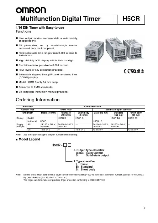
H5CRMultifunction Digital Timer1/16 DIN Timer with Easy-to-use FunctionsI Nine output modes accommodate a wide varietyof applications.I All parameters set by scroll-through menusaccessed from the front panel.I Field-selectable time ranges from 0.001 second to 9999 hours.I High visibility LCD display with built-in backlight.I Precision control possible to 0.001 second.I Four levels of key protection provided.I Selectable elapsed time (UP) and remaining time(DOWN) display.I Model H5CR-S only 64 mm deep.I Conforms to EMC standards.ISix-language instruction manual provided.Ordering InformationNote:Add the supply voltage to the part number when ordering.IModel LegendNote:Models with a finger safe terminal cover can be ordered by adding “-500” to the end of the model number. (Except for H5CR-L #)e.g., H5CR-B-500 (100 to 240 VDC, 50/60 Hz)The finger safe terminal cover provides finger protection conforming to VDE0106/P100.RC+Functions 9 field selectableContact type SPDT relay Solid-state open collectorUnit Depth Basic (78 mm)Standard (100mm)Short body (64mm)Basic (78 mm)Standard (100mm)Short body (64mm)Display Backlit ---H5CR-B H5CR-S---H5CR-BS H5CR-SSNot backlit H5CR-L------H5CR-LS------Supply voltagesAC 24/100 to 240V, 50/60 Hz 24/100 to 240V, 50/60 Hz ---24/100 to 240V, 50/60 Hz 24/100 to 240V, 50/60 Hz ---DC12 to 24 V---12 to 24 V12 to 24 V---12 to 24 VIAccessories (Order Separately)Note:1.Y92A-48G is a finger safe terminal cover which is attached to the P3G-08 Socket.2.Supplied with each Unit.SpecificationsNameModelHard cover Y92A-48Soft coverY92A-48F1Track Mounting/Front Connecting Socket (for H5CR-L # only)---P2CF-08Finger safe type P2CF-08-E Back Connecting Socket (for H5CR-L # only)---P3G-08Finger safe typeP3G-08 with Y92A-48G (see note 1)Finger Safe Terminal Cover for H5CR-B #/-S #Y92A-48T Flush Mounting Adapter (see note 2)Y92F-30ModelH5CR-L (Basic type)H5CR-B (Standard type)H5CR-S (Short body type)Classification Digital timerMountingFlush or Surface mounting Flush mountingExternal connections 8P socket Screw terminals (M3.5 screw)Enclosure ratings IP40IP54 (panel surface)Display modes Elapsed time (UP), remaining time (DOWN)Output modes A, A-1, A-2, A-3, b, b-1, d, E, FReset system Power reset (except A-3, b-1, and F modes), External, manual, automatic resets (internal according to A-1, b, b-1, d, and E mode operation)Input signals Start, reset inputsStart, reset, gate, key protect inputsInput method No-voltage input: Via opening and closing of contactControl outputs SPDT contact output and transistor output (NPN open collector)Display LCD without backlight LCD with backlight Digits4 digitsMax. time settings 9.999 s (0.001 s units), 99.99 s (0.01 s units), 999.9 s (0.1 s unit), 9999 s (1 s unit), 99 min 59 s (1 s unit), 999.9 min (0.1 min unit), 9999 min (1 min unit), 99 hr 59 min (1 min unit), 999.9 hr (0.1 hr unit), 9999 hr (1 hr unit)Memory backup Backup time for power interruption: Approx. 10 years at 20 C Mounting method DIN track mounting, surface mounting, and flush mounting Flush mounting Approved standardsUL508, CSA C22.2 No. 14Conforms to EN61010-1IRatingsICharacteristicsModelH5CR-L (Basic type)H5CR-B (Standard type)H5CR-S (Short body type)Rated supply voltage100 to 240 VAC (50/60 Hz)24 VAC (50/60 Hz)12 to 24 VDC (permissible ripple: 20% max.)100 to 240 VAC (50/60 Hz)24 VAC (50/60 Hz)12 to 24 VDC (permissible ripple: 20% max.)Operating voltage range 85% to 110% of rated voltagePower consumption Approx. 3 VA at 50 Hz, 240 VAC; approx. 1 W at 24 VDCApprox. 5 VA at 50 Hz, 240 VAC Approx. 2 W at 24 VDCReset and control signals Min. pulse width 1 ms/20ms selectable Gate ---Min. pulse width: Approx. 20 ms Key protect ---Response time: 1 sOne-shot time0.1 to 20 s (select from 7 kinds) or sustainedPower reset (except A-3, b-1, and F mode)Min. power opening time: 0.5 s Signal, reset, gate inputsNo-voltage input ON impedance: 1 k W max. (Approx. 2 mA when 0 W )ON residual voltage:2 V max.OFF impedance:100 k W min.Key protect input---No-voltage inputON impedance: 1 k W max. (Approx. 2 mA when 0 W )ON residual voltage:1 V max.OFF impedance:100 k W min.Control outputs Contacts: 5 A at 250 VAC, resistance load (cos f = 1)Transistor output: Open collector 100mA at 30 VDC max. residual voltage 2 V max. (Approx. 1 V)Ambient temperature –10 C to 55 C (with no icing)Storage temperature –25 C to 65 C (with no icing)Ambient humidity 35% to 85%Case Light grayRepeat accuracy (including temperature and voltage effects)Power start: 0.01% 0.05 s max.Control signal start: 0.005% 0.03 s max. *(rate for set value)Insulation resistance 100 M W min. (at 500 VDC) (between current-carrying terminal and exposed non-current-carrying metal parts, and between non-continuous contacts)Dielectric strength 2,000 VAC, 50/60 Hz for 1 min (between current-carrying terminal and exposed non-current-carrying metal parts) for 100 to 240 VAC type 1,000 VAC for 24VAC/12 to 24 VDC transistor output typeSurge voltage3 kV (between power terminals) for 100 to 240 VAC type, 1 kV for 24 VAC/12 to 24 VDC type4.5 kV (between current-carrying terminal and exposed non-current-carrying metal parts) for 100 to 240 VAC type, 1.5 kV for 24 VAC/12 to 24 VDC typeNoise immunity 2 kV (between power terminals)( 480 V for 12 to 24 VDC) and 600 V (between input terminals), square-wave noise by noise simulator (pulse width: 100 ns/1 m s, 1-ns rise)Static immunity Malfunction: 8 kV; destruction: 15 kVVibration Destruction 10 to 55 Hz with 0.75-mm single amplitude each in three directions Malfunction 10 to 55 Hz with 0.5-mm single amplitude each in three directions ShockDestruction 294 m/s 2 (30G) each in three directions Malfunction98 m/s 2 (10G) each in three directions Life expectancy Mechanical 10 million operations min.Electrical100,000 operations min. (5 A at 250 VAC in load resistance)EMC(EMI):EN50081-2Emission Enclosure:EN55011 Group 1 class A Emission AC Mains:EN55011 Group 1 class A (EMS):EN50082-2Immunity ESD:EN61000-4-2: 4 kV contact discharge (level 2)8 kV air discharge (level 3)Immunity RF-interference:ENV50140:10 V/m (80 MHz to 1 GHz) (level 3)Immunity Conducted Disturbance:ENV50141:10 V (0.15 to 80 MHz) (level 3)Immunity Burst:EN61000-4-4: 2 kV power-line (level 3)2 kV I/O signal-line (level 4)WeightH5CR-L: Approx. 105 g, H5CR-B: Approx. 160 g, H5CR-S: Approx. 120 gNomenclatureIFactory SettingsThe following table shows the timer settings when it is shipped. Please change the settings as necessary to suit the system before opera-tion. Settings and the display receive power from the internal battery and are therefore unaffected by external power interruptions.Note:With the initial settings, there will be no output even if the power supply is connected. External inputs and outputs cannot be used without a power supply.1213Model H5CR-B (Standard)/H5CR-S (Short body)H5CR-L (Basic)Time range - -. - -s Present value 0.00 s Presets0.00 s UP/DOWN mode UPOutput mode A: Signal on delay (I)Output time Sustained Input signal time 20 ms Key protect level KP-1---OperationI Block DiagramI I/O FunctionsInputs Start signal Stops timing in A-2 and A-3 (power on delay) modes. Starts timing in other modes.Reset Resets present value (to zero in UP modes, to preset in DOWN mode).Count inputs are not accepted while reset input is ON.Reset indicator lit while reset input is ON.Gate Inhibits timer operation.Key protect Makes keys inoperative according to key protect level.Key protected indicator lit while key protect input is ON.Effective when power supply is turned off.Effective when protect terminals are shorted.Outputs Control output (OUT)Outputs made according to designated output mode when corresponding preset is reached.I Operational OverviewThis flowchart shows operation common to all H5CR models. Refer to the following Setting Item Table for details on the operation of specific models.I Setting Item TableNote: 1.Changes made in setting mode become effective when run mode is entered.2.The time range setting appears first when setting mode is entered.3.*The key protection function is not included in the H5CR-L.<KP-4><KP-3>I ExamplesRun ModeChanging the Set ValueT o change the set value from 3 hr 5 min to 4 hr 5 min, press the 3key so that the number 4 appears in the hour’s place.•Pressing keys 1 through 4 increments the corresponding col-umn by 1.•The columns can be changed in any order, but the output willbe turned ON if the set value is less than the present value.•Nonsignificant zeros are suppressed on the set value display.Note:Read Changing Set Values in the Precautions section,page16, before changing the Timer set value during op-eration.Setting ModeChanging Settings in the Set Mode1.Press the MODE key to switch from run mode to set mode.•The Timer will continue operation if switched from run mode to set mode during operation.•The MODE key will be locked if the key protection function is enabled.•Settings changed in the set mode are not effective until run mode is entered. As the operating conditions will change in this case, always reset operation with the RESET key or a re-set input.2.Press the MODE key to scroll successively through the items that can be set.3.Changing the selected item•Press the MODE key until the desired item appears.•Change the item setting by pressing keys 1 through 4. (Pressthe DISPLAY key to switch back from set mode to run mode.)ITiming ChartsThe gate input is not included in the H5CR-L.Output mode A: Signal ON delay 1 (Timer resets when power comes ON.)Output mode A-1: Signal ON delay 2 (Timer resets when power comes ON.)Output mode A-2: Power ON delay 1 (Timer resets when power comes ON.)Output mode A-3: Power ON delay 2 (Timer does not reset when power comes ON.)Power Start signalGate ResetControl outputSet valueTiming diagramUPDOWNSet valueTiming starts when the start signal goes ON.While the start signal is ON, the timer starts when the power comes ON or when the reset input goes OFF .The control output is controlled using a sustained or one-shot time period.Basic OperationPower**Start signal inputTimingOutput* Output is instantaneous when setting is 0.** Start signal input is disabled during timing.Power Start signalGate ResetControl outputSet valueTiming diagramUPDOWNSet valueTiming starts when the start signal goes ON, and is reset when the start signal goes OFF .While the start signal is ON, the timer starts when the power comes ON or when the reset input goes OFF .The control output is controlled using a sustained or one-shot time period.*Output is instantaneous when setting is 0.Basic OperationPower Start signal inputTimingOutputPower Start signalGate ResetControl outputSet valueTiming diagramUPDOWNSet valueTiming starts when the reset input goes OFF .The start signal disables the timing function (i.e., same function as the gate input).The control output is controlled using a sustained or one-shot time period.*Output is instantaneous when setting is 0.Basic OperationPower TimingOutputPower Start signalGate ResetControl outputSet valueTiming diagramUP DOWNSet valueTiming starts when the reset input goes OFF .The start signal disables the timing function (i.e., same function as the gate input).The control output is controlled using a sustained or one-shot time period.*Output is instantaneous when setting is 0.Basic OperationPower TimingOutputSustainedOutput mode b-1: Repeat cycle 2 (Timer does not reset when power comes ON.)Power Start signalGate ResetControl output* Normal output operation will not be possible if the set time is too short.Set the value to at least 100 ms (contact output ** Start signal input is disabled during timing.TimingTiming Timing Timing Timing starts when the start signal goes ON.The control output is turned ON when time is up.While the start signal is ON, the timer starts when the power comes ON or when the reset input goes OFF .* Normal output operation will not be possible if the set time is too short.Set the value to at least 100 ms (contact output ** Start signal input is disabled during timing.Basic OperationPower Start signal OutputTimingTiming Timing Timing Timing starts when the start signal goes ON.The status of the control output is reversed when time is up (OFF at start).While the start signal is ON, the timer starts when the power comes ON or when the reset input goes OFF .* Normal output operation will not be possible if the set time is too short.Set the value to at least 100 ms (contact output ** Start signal input is disabled during timing.Sustained Basic OperationStart signal TimingTimingTiming starts when the start signal goes ON.The control output comes ON when time is up.While the start signal is ON, the timer starts when power comes ON or when the reset input goes OFF .Basic OperationStart signal * Normal output operation will not be possible if the set time is too short.Set the value to at least 100 ms (contact output ** Start signal input is disabled during timing.Sustained TimingTimingNote:A twin timer can be created by using one of the repeat modes. For example, if the set value is 60 s and the one shot time is 10 s in repeat mode, the control output will turn OFF for 50 s and ON for 10 s. (In the first cycle, however, the control output will turn OFF for 60 s.) In this way, the work of two timers can be performed by a single timer.Output mode E: Interval (Timer resets when power comes ON.)Output mode F: Cumulative (Timer does not reset when power comes ON.)* Output functions only during start signal input when setting is 0.** Start signal input is enabled during timing.Power Start signal OutputTimingTiming starts when the start signal comes ON.The control output is reset when time is up.While the start signal is ON, the timer starts when power comes ON or when the reset input goes OFF .* Output is disabled when the setting is 0.** Start signal input is disabled during timing.Basic OperationPower Start signal OutputTimingStart signal enables timing (timing is stopped when the start signal is OFF or when the power is OFF).A sustained control output is used.* Output is instantaneous when setting is 0.SustainedBasic OperationPower Start signal OutputTimingTiming10 s50 s 60 sDimensionsNote:All units are in millimeters unless otherwise indicated.484884.063.760.714.344.8 x 44.8 484866444.8 x 44.8H5CR-LSurface/Flush Mounting H5CR-BFlush MountingH5CR-S Flush Mounting4848100644.8 x 44.8IDimensions with Y92F-30 Flush Mounting Adapter4858685.95848610092.8AH5CR-BH5CR-SPanel CutoutsPanel cutouts areas shown below.(according to DIN43700).Y92F-30Flush mounting adapterPanel Y92F-30Flush mounting adapterPanel Note 1. The mounting panel thicknessshould be 1 to 4 mm.2. It is possible to mount timers side by side, but only horizontally.H5CR-LP2CF-08584866460 min.60 min.45+0.6-045+0.6-0+10A = {48n - 2.5 + (n -1) x 4}Panel Flush mountingadapter P3G-08Rear surfaceconnection socket44.8 x 44.8With Y92A-48F1 attached.44.8 x 44.8+1A = (51n - 5.5)With Y92A-48 attached.IAccessories (Order Separately)Eight, M3.5 x 7.5 semsT wo, 4.5 dia.holes70 max.50 max.20.3 max.7.83 4.535.44P2CF-08-E (Finger Safe Terminal Type)Conforming to VDE0106/P10050 max.40±0.270 max.M3.5 x 7.5 semsT wo, 4.5 dia. holes7.835.421.5 max.20.31931.35 4.54527 dia.45 4.917Back Connecting SocketP3G-08Terminal Arrangement/Internal Connections (Bottom View)Finger Safe Terminal CoverConforming to VDE0106/P100Y92A-48G(Attachment for P3G-08 Socket)Y92A-48T(Attachment for H5CR-B (/-S ()Hard Cover Y92A-48Soft Cover Y92A-48F1T welve, 6.4 dia. holes3447.7 x 47.748 x 4847.416.524.627.6InstallationI Terminal ArrangementNote:Do not connect unused terminals.I ConnectionsPrecautionsIPower Supplies•The input circuit is not insulated from the power supply circuit.The internal circuit might be damaged by a surrounding AC cir-cuit, so use an insulated AC power supply with equipment con-nected to the input circuit.•If power is interrupted for less than 10 ms, operation will continue normally. If power is interrupted for between 10 and 500 ms, op-eration will be inconsistent, and timing may stop or reset, de-pending on the mode.•Connect the power supply voltage through a relay or switch in such a way that the voltage reaches a fixed value immediately.•Depending on switching frequency, current surges may degrade relay contacts; relays with a capacity greater than 10 A are rec-ommended.IInput and Output•Do not use external sources to increase the voltage of input sig-nals (control signal, reset, gate, and key protection).•Be sure that the load of the control output (contact, transistor) is less than the maximum values indicated in the specifications. If the output load exceeds the recommended value, the life span of the contact output type will be shortened dramatically, and the transistor of the transistor output type will be damaged.•The transistor output is insulated from the internal circuitry by a photocoupler, so either NPN or PNP transistors can be used.ISelf-diagnostic Function•The following displays will appear if an error occurs. The present value and output enter the same status as after pressing the RE-SET key.IChanging Set Values•The Timer set value can be changed while the timer is operating,so a high value can be set temporarily to inactivate the timer, or a low value can be set to activate the timer more quickly. (If the set value is changed accidentally during operation, the timer might be activated. Therefore, turn the key protection input ON unless the set value is being changed.)•To avoid changing the output when changing the set value, it is recommended to begin changing the set value by entering a large number in the higher digit.IOperation with a Set Value of 0•Operation with a set value of 0 will vary depending on the output mode. For details, refer to Timing Charts.IOperating Environment•When using the Timer in an area with much electronic noise,separate the Timer, wiring, and the equipment which generates the input signals as far as possible from the noise sources. It is also recommended to shield the input signal wiring to prevent electronic interference.•Organic solvents (such as paint thinner), as well as very acidic or basic solutions might damage the outer casing of the Timer.IOther•When the Timer is installed in a control box and tests are con-ducted which may damage the Timer ’s internal circuitry (for ex-ample, a test measuring the maximum voltage difference between the control circuit and metal components), remove the Timer from the control box or short circuit the terminals.&DXWLRQThis product contains a lithium battery. Lithium batteries ex-plode if incinerated. Dispose of the Digital Timer as a non-com-bustible item.DisplayError Output status CorrectionSetCPU OFFPress RESET keyNo change MemorySet at the factoryA AIn the interest of product improvement, specifications are subject to change without notice.ALL DIMENSIONS SHOWN ARE IN MILLIMETERS.To convert millimeters into inches, multiply by 0.03937. T o convert grams into ounces, multiply by 0.03527.Cat. No. L035-E1-4B OMRON CorporationIndustrial Automation CompanyMeasuring and Supervisory Controls Department Shiokoji Horikawa, Shimogyo-ku Kyoto, 600-8530 JapanT el: (81)75-344-7108/Fax: (81)75-344-7189Printed in Japan 0401-1.5C。
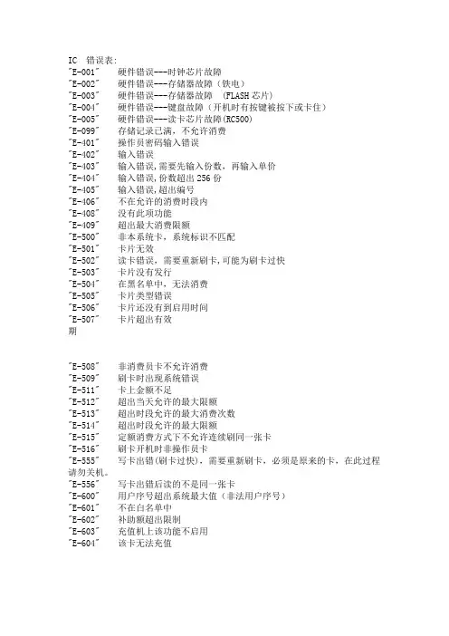
IC 错误表:"E-001" 硬件错误---时钟芯片故障"E-002" 硬件错误---存储器故障(铁电)"E-003" 硬件错误---存储器故障(FLASH芯片)"E-004" 硬件错误---键盘故障(开机时有按键被按下或卡住)"E-005" 硬件错误---读卡芯片故障(RC500)"E-099" 存储记录已满,不允许消费"E-401" 操作员密码输入错误"E-402" 输入错误"E-403" 输入错误,需要先输入份数,再输入单价"E-404" 输入错误,份数超出256份"E-405" 输入错误,超出编号"E-406" 不在允许的消费时段内"E-408" 没有此项功能"E-409" 超出最大消费限额"E-500" 非本系统卡,系统标识不匹配"E-501" 卡片无效"E-502" 读卡错误,需要重新刷卡,可能为刷卡过快"E-503" 卡片没有发行"E-504" 在黑名单中,无法消费"E-505" 卡片类型错误"E-506" 卡片还没有到启用时间"E-507" 卡片超出有效期"E-508" 非消费员卡不允许消费"E-509" 刷卡时出现系统错误"E-511" 卡上金额不足"E-512" 超出当天允许的最大限额"E-513" 超出时段允许的最大消费次数"E-514" 超出时段允许的最大限额"E-515" 定额消费方式下不允许连续刷同一张卡"E-516" 刷卡开机时非操作员卡"E-555" 写卡出错(刷卡过快),需要重新刷卡,必须是原来的卡,在此过程请勿关机。
BDE错误码对照表0x0000 (0) = SUCcessful completion.0x0021 (33) = System Error0x0022 (34) = Object of Interest Not Found0x0023 (35) = Physical Data Corruption0x0024 (36) = I/O Related Error0x0025 (37) = Resource or Limit Error0x0026 (38) = Data Integrity Violation0x0027 (39) = Invalid Request0x0028 (40) = Lock Violation0x0029 (41) = /Security Violation0x002A (42) = Invalid Context0x002B (43) = OS Error0x002C (44) = Network Error0x002D (45) = Optional Parameter0x002E (46) = Query Processor0x002F (47) = Version Mismatch0x0030 (48) = Capability Not Supported0x0031 (49) = System Configuration Error0x0032 (50) = Warning0x0033 (51) = Miscellaneous0x0034 (52) = Compatibility Error0x003E (62) = Driver Specific Error0x003F (63) = Internal Symbol0x2101 (8449) = Cannot open a system file.0x2102 (8450) = I/O error on a system file.0x2103 (8451) = Data structure corruption.0x2104 (8452) = Cannot find Engine configuration file.0x2105 (8453) = Cannot write to Engine configuration file.0x2106 (8454) = Cannot initialize with different configuration file.0x2107 (8455) = System has been illegally re-entered.0x2108 (8456) = Cannot locate IDAPI32 .DLL.0x2109 (8457) = Cannot load IDAPI32 .DLL.0x210A (8458) = Cannot load an IDAPI service library.0x210B (8459) = Cannot create or open temporary file.0x2201 (8705) = At beginning of table.0x2202 (8706) = At end of table.0x2203 (8707) = Record moved because key value changed.0x2204 (8708) = Record/Key deleted.0x2205 (8709) = No current record.0x2206 (8710) = Could not find record.0x2207 (8711) = End of BLOB.0x2208 (8712) = Could not find object.0x2209 (8713) = Could not find family member.0x220A (8714) = BLOB file is missing.0x220B (8715) = Could not find language driver.0x2301 (8961) = Corrupt table/index header.0x2302 (8962) = Corrupt file - other than header.0x2303 (8963) = Corrupt Memo/BLOB file.0x2305 (8965) = Corrupt index.0x2306 (8966) = Corrupt lock file.0x2307 (8967) = Corrupt family file.0x2308 (8968) = Corrupt or missing .VAL file.0x2309 (8969) = Foreign index file format.0x2401 (9217) = Read failure.0x2402 (9218) = Write failure.0x2403 (9219) = Cannot access Directory.0x2404 (9220) = File Delete operation failed.0x2405 (9221) = Cannot access file.0x2406 (9222) = Access to table disabled because of previous error.0x2501 (9473) = Insufficient memory for this operation.0x2502 (9474) = Not enough file handles.0x2503 (9475) = Insufficient disk space.0x2504 (9476) = Temporary table resource limit.0x2505 (9477) = Record size is too big for table.0x2506 (9478) = Too many open cursors.0x2507 (9479) = Table is full.0x2508 (9480) = Too many s from this workstation.0x2509 (9481) = Serial number limit (Paradox).0x250A (9482) = Some internal limit (see context).0x250B (9483) = Too many open tables.0x250C (9484) = Too many cursors per table.0x250D (9485) = Too many record locks on table.0x250E (9486) = Too many clients.0x250F (9487) = Too many indexes on table.0x2510 (9488) = Too many sessions.0x2511 (9489) = Too many open databases.0x2512 (9490) = Too many passs.0x2513 (9491) = Too many active drivers.0x2514 (9492) = Too many fields in Table Create.0x2515 (9493) = Too many table locks.0x2516 (9494) = Too many open BLOBs.0x2517 (9495) = Lock file has grown too large.0x2518 (9496) = Too many open queries.0x251A (9498) = Too many BLOBs.0x251B (9499) = File name is too long for a Paradox version 5.0 table.0x251C (9500) = Row fetch limit exceeded.0x251D (9501) = Long name not allowed for this tablelevel.0x2601 (9729) = Key violation.0x2602 (9730) = Minimum validity check failed.0x2603 (9731) = Maximum validity check failed.0x2604 (9732) = Field value required.0x2605 (9733) = Master record missing.0x2606 (9734) = Master has detail records. Cannot delete or modify.0x2607 (9735) = Master table level is incorrect.0x2608 (9736) = Field value out of lookup table range.0x2609 (9737) = Lookup Table Open operation failed.0x260A (9738) = Detail Table Open operation failed.0x260B (9739) = Master Table Open operation failed.0x260C (9740) = Field is blank.0x260D (9741) = Link to master table already defined.0x260E (9742) = Master table is open.0x260F (9743) = Detail table(s) exist.0x2610 (9744) = Master has detail records. Cannot empty it.0x2611 (9745) = Self referencing referential integrity must be entered one at a time with no other changes to the table 0x2612 (9746) = Detail table is open.0x2613 (9747) = Cannot make this master a detail of another table if its details are not empty.0x2614 (9748) = Referential integrity fields must be indexed.0x2615 (9749) = A table linked by referential integrity requires password to open.0x2616 (9750) = Field(s) linked to more than one master.0x2617 (9751) = EXPression validity check failed.0x2701 (9985) = Number is out of range.0x2702 (9986) = Invalid parameter.0x2703 (9987) = Invalid file name.0x2704 (9988) = File does not exist.0x2705 (9989) = Invalid option.0x2706 (9990) = Invalid handle to the function.0x2707 (9991) = Unknown table type.0x2708 (9992) = Cannot open file.0x2709 (9993) = Cannot redefine primary key.0x270A (9994) = Cannot change this RINTDesc.0x270B (9995) = Foreign and primary key do not match.0x270C (9996) = Invalid modify request.0x270D (9997) = Index does not exist.0x270E (9998) = Invalid offset into the BLOB.0x270F (9999) = Invalid descriptor number.0x2710 (10000) = Invalid field type.0x2711 (10001) = Invalid field descriptor.0x2712 (10002) = Invalid field transformation.0x2713 (10003) = Invalid record structure.0x2714 (10004) = Invalid descriptor.0x2715 (10005) = Invalid array of index descriptors.0x2716 (10006) = Invalid array of validity check descriptors.0x2717 (10007) = Invalid array of referential integrity descriptors.0x2718 (10008) = Invalid ordering of tables during restructure.0x2719 (10009) = Name not unique in this context.0x271A (10010) = Index name required.0x271B (10011) = Invalid session handle.0x271C (10012) = invalid restructure operation.0x271D (10013) = Driver not known to system.0x271E (10014) = Unknown database.0x271F (10015) = Invalid password given.0x2720 (10016) = No callback function.0x2721 (10017) = Invalid callback buffer length.0x2722 (10018) = Invalid directory.0x2723 (10019) = Translate Error. Value out of bounds.0x2724 (10020) = Cannot set cursor of one table to another.0x2725 (10021) = Bookmarks do not match table.0x2726 (10022) = Invalid index/tag name.0x2727 (10023) = Invalid index descriptor.0x2728 (10024) = Table does not exist.0x2729 (10025) = Table has too many users.0x272A (10026) = Cannot evaluate Key or Key does not pass filter condition. 0x272B (10027) = Index alrea。
行云流水 OBD-II标准故障代码表OBD-II标准故障码表:________________________________________P0000 没有故障(FORD)P0100 空气流量计线路不良P0101 空气流量计不良(讯号值错误)P0102 空气流量计线路输入电压太低P0103 空气流量计线路输入电压太高P0104 空气流量计线路间歇故障P0105 空气压力传感器线路不良或无讯号输出(FORD)P0106 空气压力传感器系统电压值不正确或打马达时当引擎发动后MAP讯号相同(FORD)P0107 空气压力传器系统输入电压太低P0108 空气压力传器系统输入电压太高P0109 进气温度传感器线路间歇性不良P0110 进气温度传感器线路间歇性不良P0111 进气温度传感器线路(讯号值错误)P0112 进气温度传感器线路电压太低P0113 进气温度传感器线路输入电压太高P0114 进气温度传感器线路间歇故障P0115 水温传感器线路不良P0116 水温传感器线路(讯号错误)P0116 引擎发动20分钟以上,温度仍在30℃以下(TOYOTA)P0117 水温传感器电压太低P0118 水温传感器电压太高P0119 水温传感器电压线路间歇故障P0120 节汽门传感器线路不良P0120 节汽门传感器信号低于0.1V或高于4.9V(TOYOTA)P0121 节汽门传感器线路不良P0121 辅助节汽门传感器电压值不正确或调整不良(TOYOTA)P0121 节汽门传感器的电压无法和进气压力传感器的电压配合(CHRYSER) P0122 节汽门传感器讯号电压太低P0122 辅整助节汽门传感器讯号太高P0123 节汽门传感器线路电压太高P0123 节汽门传感器电压太高P0124 节汽门传感器线路间歇故障P0125 水温传感器感测进入回路(CLOSE LOOP)控制时间太长P0126 水温传感器电压值不稳定P0130 含氧传感器线路失效(BANK 1,SENSOR 1)P0131 含氧传感器线路电压太低或短路(BANK 1,SENSOR 1)P0132 含氧传感器线路电压太高(BANK1,STESOR 1)P0133 含氧传感器反应太慢 (BANK1,STESOR 1)P0134 含氧传感器反应次数太少或无作用 (BANK1,STESOR 1)P0136 含氧传感器失效 (BANK1,STESOR 2)P0136 含氧传感器在引擎负荷时电压值不正确 (BANK1,STESOR 2) P0137 含氧传感器线路短路 (BANKZ) (BANK2)P0137 含氧传感器电压太低 (BANK1,STESOR 2)P0138 含氧传感器电压太高 (BANK1,STESOR 2)P0139 含氧传感器反应太慢 (BANK1,STESOR 2)P0140 含氧传器反应次数太少或无作用 (BANK1,STESOR 2)P0141 含氧传感器加热线路不良 (BANK1,STESOR 2)P0142 含氧传感器加热线路不良 (BANK1,STESOR 3)P0143 含氧传感器电压太低 (BANK1,STESOR 3)P0144 含氧传感器电压太高 (BANK1,STESOR 3)P0145 含氧传感器反应太慢 (BANK1,STESOR 3)P0146 含氧传感器无作用,反应次数太少 (BANK1,STESOR 3)P0147 含氧传感器加热线路不良 (BANK1,STESOR 3)P0150 含氧传感器不作用 (BANK2,STESOR 1)P0151 含氧传感器电压太低 (BANK2,STESOR 1)P0152 含氧传感器电压太高 (BANK2,STESOR 1)P0153 含氧传感器反应太慢 (BANK2,STESOR 1)P0154 含氧传感器反应次数太少 (BANK2,STESOR 1)P0155 含氧传感器加热线路不良 (BANK2,STESOR 1)P0157 含氧传感器电压太低 (BANK2,STESOR 2)P0158 含氧传感器电压太高 (BANK2,STESOR 2)P0159 含氧传感器反应太慢 (BANK2,STESOR 2)P0160 含氧传感器反应次数太少或无作用 (BANK2,STESOR 2) P0161 含氧传感顺加热线路不良 (BANK2,STESOR 2)P0162 含氧传感器不作用 (BANK2,STESOR 3)P0163 含氧传感器电压太低 (BANK2,STESOR 3)P0164 含氧传感器电压太高 (BANK2,STESOR 3)P0165 含氧传感器反应太慢 (BANK2,STESOR 3)P0166 含氧传感居反应次数太少或无作用 (BANK2,STESOR 3) P0167 含氧传感器加热线路不良 (BANK2,STESOR 3)P0170 燃料修正(混合比)不良 (BAND 1)P0171 混合比太稀 (BANK 1)P0172 混合比太浓(BANK 1)P0173 燃料修正失效(BANK 2)P0174 混合比太稀 (BANK 2)P0175 混合比太浓 (BANK 2)P0176 燃料含水量传感器线路失效P0177 燃料含水量传感器线路电压值不正确P0178 燃料含水量传感器线路电压太低P0179 燃料含水量传感器线路电压太高P0180 A组燃料温度传感器线路的失效P0181 A组燃料温度传感器线路电压不正确P0182 A组燃料温度传器线路电压太低P0183 A组燃料温度传器线路电压太高P0184 A组燃料温度传器线路间歇故障P0185 B组燃料温度传感器线路失效P0186 B组燃料温度传感器线路电压不正确P0187 B组燃料温度传感器线路电压太低P0188 B组燃料温度传感器线路电压太高P0189 B组燃料温度传感器线路间歇故障P0190 燃油分供管油压传感器线路失效P0191 燃油分供管油压传感器线路电压不正确P0192 燃油分供管油压传感器线路电压太低P0193 燃油分供管油压传感器线路电压太高P0194 燃油分供管油压传器线路间歇故障P0195 引擎机油温度传感器线路失效P0196 引擎机油温度传感器线路电压太低P0197 引擎机油温度传感器线路电压太高P0198 引擎机油温度传感器线路电压太高P0199 引擎机油温度传感器线路间歇故障P0200 喷油咀控制线路失效P0201 第1缸喷油咀控制线路失效P0202 第2缸喷油咀控制线路失效P0203 第3缸喷油咀控制线路失效P0204 第4缸喷油咀控制线路失效P0205 第5缸喷油咀控制线路失效P0206 第6缸喷油咀控制线路失效P0207 第7缸喷油咀控制线路失效P0208 第8缸喷油咀控制线路失效P0209 第9缸喷油咀控制线路不良P0210 第10缸喷油咀控制线路不良P0211 第11缸喷油咀控制线路不良P0212 第12缸喷油咀控制线路不良P0213 1号冷车启动喷油咀控制线路不良P0214 2号冷车启动喷油咀控制线路不良P0215 引擎限速断油电磁伐(SHOUT OFF SOLENOID)控制线路失效P0216 喷射正时控制线路失效P0217 引擎处于过热状态P0218 变速箱处于过热状态P0219 引擎转速超过电脑设定值P0220 辅度助节汽门传感器或节汽门传感器B组线路失效P0220 汽油泵继电器控制线路不良(CHRYLSER)P0221 辅助节汽门传感器或节汽门传感器B组线路电压值不正确P0222 辅助节汽门传感器讯号或节汽门传感器B组线路电压太低P0223 辅助节汽门传感器讯号或节汽门传感器B组线路电压太高P0224 辅助节汽门传感器讯号或节汽门传感器B组线路间歇故障P0225 辅助节汽门传感器或节汽门传感器C组线路失效P0226 辅助节汽门传感器或节汽门传感器C组线路电压值不正确P0227 辅助节汽门传感器讯号或节汽门传感器CC组线路电压太低P0228 辅助节汽门传感器讯号或节汽门传感器C组线路电压太高P0229 辅助节汽门传感器讯号或节汽门传感器C组线路间歇故障P0230 汽油泵主线路失效P0231 汽油泵回归电压太低(GM)P0231 汽油泵副线路电压太低P0232 汽油泵回归电压太高P0232 汽油泵副线路电压太高P0233 汽油泵副线路间歇故障P0235 滑轮增压器压力传器A线路失效P0236 滑轮增压器压力传 A线路电压值不正确P0237 滑轮增压器压力传感器A线路电压太低P0238 滑轮增压器压力传感器A线路电压太高P0239 滑轮增压器压力传感器B线路失效P0240 滑轮增压器压力传感器B线路电压值不正确P0241 滑轮增压器压力传器B线路电压太低P0242 滑轮增压压力传器B线路电压太高P0243 滑轮增压器排气控制电磁伐控制线路A失效P0244 滑轮增压器排气控制电磁伐控制线路A电脑不正确P0245 滑轮增压器排气控制电磁伐A太低P0246 滑轮增压器排气控制电磁伐控制线路A电压太高P0247 滑轮增压排气控制电磁伐控制线路B失效P0248 滑轮增压器排气控制电磁伐控制线路B值不正确P0249 滑轮增压器排气控制电磁伐控制线路B电压太低P0250 滑轮增压器排气控制电磁伐控制线路B电压太高P0251 柴油引擎A组喷射泵凸轮或轮子失效P0252 柴油引擎A组喷射泵凸轮或轮子电压值不正确P0253 柴油引擎A组喷射泵凸轮或轮子电压太低P0254 柴油引擎A组喷射泵凸轮或轮子电压太高P0255 柴油引擎A组喷射泵凸轮或轮子间歇故障P0256 柴油引擎A组喷射泵凸轮或轮子失效P0257 柴油引擎A组喷射泵凸轮或轮子电压值不正确P0258 柴油引擎A组喷射泵凸轮或轮子电压太低P0259 柴油引擎A组喷射泵凸轮或轮子电压太高P0260 柴油引擎A组喷射泵凸轮或轮子间歇故障P0262 第1缸喷油咀线路电压太高P0263 第1缸运转不良;第8缸动力平衡不良(GM) P0264 第2缸喷油咀线路电压太低P0265 第2缸喷油咀线路电压太高P0266 第2缸运转不良;第7缸动力平衡不良(GM) P0267 第3缸喷油咀线路电压太低P0268 第3缸喷油咀线路电压太高P0269 第3缸运转不良;第2缸动力平衡不良(GM) P0270 第4缸喷油咀线路电压太低P0271 第4缸喷油咀线路电压太高P0272 第4缸运转不良;第6缸致力平衡不良 (GM) P0273 第5缸喷油咀线路电压太低P0274 第5缸喷油咀线路电压太高P0275 第5缸运转不良;第5缸动力平衡不良(GM) P0276 第6缸喷油咀线路电压太低P0277 第6缸喷油咀线路电压太高P0278 第6缸运转不良;第4缸动力平衡不良(GM) P0279 第7缸喷油咀线路电压太低P0280 第7缸喷油咀线路电压太高P0281 第7缸运转不良;第3缸动力平衡不良(GM)P0283 第8缸喷油咀线路电压太高P0284 第8缸运转不良;第1缸动力平衡不良(GM) P0285 第9缸喷油咀线路电压太低P0286 第9缸喷油咀线路电压太高P0287 第9缸运转不良P0288 第10缸喷油咀线路电压太低P0289 第10缸喷油咀线路电压太高P0290 第10缸运转不良P0291 第11缸喷油咀线路电压太低P0292 第11缸喷油咀线路电压太高P0293 第11缸运转不良P0294 第12缸喷油咀线路电压太低P0295 第12缸喷油咀线路电压太高P0296 第12缸运转不良P0297 进气压力传感器讯号一直变化(FORD)P0300 引擎曾经有失火(MISFIRE)现象P0301 第1缸曾经失火P0302 第2缸曾经失火P0303 第3缸曾经失火P0304 第4缸曾经失火P0305 第5缸曾经失火P0306 第6缸曾经失火P0307 第7缸曾经失火P0308 第8缸曾经失火P0309 第9缸曾经失火P0310 第10缸曾经失火P0311 第11缸曾经失火P0312 第12缸曾经失火P0320 分电盘点火系统引擎转速讯号线路失效P0321 分电盘点火系统引擎转速讯号线路电压值不正确P0322 分电盘点火系统引擎转速讯号线路没有讯号P0323 分电盘点火系统引擎转速讯号线路间歇故障P0324 爆震传感器线路失效(BANK 1)P0325 引擎在2000RPM以上一直没有收到爆震信号(BANK 1)(TOYOTA)P0326 爆震传感器线路电压不正确或太高(GM)(BANK1或STESOR 3)P0327 爆震传感器线路电压太低(GM)(BANK1或STESOR 3)P0328 爆震传器线路电压太高或断路(GM)(BANK1或STESOR 3)P0329 爆震传感器线路间歇故障(BANK1或STESOR 3)P030 爆震传感器线路失效(BANK 2)P0330 引擎在2000RPM以上一直没有收到爆震信号(BAND 2)(TOYOTA)P0331 引擎在2000RPM以上电压值不正确(BANK 2)P0332 爆震传感器电压太低(BANK 2)P0333 爆震传感器电压太高(BANK 2)P0334 爆震传感器电压间歇故障(BANK 2)P0335 曲轴传感器A组线路失效P0335 曲轴传感器A组线路电压值过低(ACURA/HONDA) P0336 曲轴传器A电压值不正确P0336 加热式含氧传感器线路失效P0337 曲轴传器A组线路电压太低P0338 曲轴传器A组线路电压太高P0339 曲轴传器A组线路间歇故障P0340 凸轮轴传感器线路失效P0341 凸轮轴传感器线路电压值不正确P0342 凸轮轴传感器线路电压太低P0343 凸轮轴传感器线路电压太高P0344 凸轮轴传感器线路间歇故障P0350 点火线圈一次/二次线路失效P0351 点火线圈A组一次/二次线路失效P0352 点火线圈B组一次/二次线路失效P0353 点火线圈C组一次/二次线路失效P0354 点火线圈D组一次/二次线路失效P0355 点火线圈E组一次/二次线路失效P0356 点火线圈F组一次/二次线路失效P0357 点火线圈G组一次/二次线路失效P0358 点火线圈H组一次/二次线路失效P0359 点火线圈I组一次/二次线路失效P0360 点火线圈J组一次/二次线路失效P0361 点火线圈K组一次/二次线路失效P0362 点火线圈L组一次/二次线路失效P0370 点火正时高解析参考线路A组失效P0371 点火正时参考线路A组高转速时接收太多脉冲(受到干扰)P0372 点火正时参考线路A组高转速曾收到太少的脉冲,曾收到中断脉冲(GM) P0373 点火正时参考线路A组高转速时讯号间歇性不稳定P0374 点火正时参考线路A组高转速时没有讯号P0375 点火正时高解析参考线路B组失效P0376 点火正时参考线路B组高转速时曾收太多讯号P0377 点火正时参考线路B组高转速曾收到太少讯号P0378 点火正时参考线路B组高转速时讯号间歇性不稳定P0379 点火正时参考线路B组高转速时没有讯号P0380 预热塞加热线路失效,火花增加线路不良P0381 预热塞指示灯线路失效P0385 曲轴传感器B组线路失效P0386 曲轴传感器B组线路电压值不正确P0387 曲轴传感器B组线路电压太低P0388 曲轴传感器B组线路电压太高P0389 曲轴传感器B组线路间歇故障P0390 正时皮带打滑或跳齿(FORD)P0391 第1组高压线圈低压线路不良(FORD)P0392 第2组高压线圈低压线路不良(FORD)P0393 第3组高压线圈低压线路不良(FORD)P0394 第4组高压线圈低压线路不良(FORD)P0395 第5组高压线圈低压线路不良(FORD)P0396 第6组高压线圈低压线路不良(FORD)P0400 EGR阀系统流量控制失效P0401 EGR阀系统流量控制不正确或太低(阻塞)P0401 引擎达工作温度,车速80KM以上行驶3~5分钟,但EGR温度信号低于40℃P0402 EGR阀系统流量控制太大(泄漏)P0403 EGR阀流量电磁伐控制线路不良P0404 EGR阀流量电磁伐控制线路电太值不正确P0405 EGR阀流量传感器线路A组电压太低P0406 EGR阀流量传感器线路A组电压太高P0407 EGR阀流量传感器线路B组电压太低P0408 EGR阀流量传感器线路B组电压太高P0410 二次空气导入系统失效P0411 二次空气导入系统流量值不正确P0412 二次空气导入系统流量电磁阀A组线路失效P0413 二次空气导入系统流量电磁阀A组线路断路P0414 二次空气导入系统流量电磁阀A组线路短路P0415 二次空气导入系统流量电磁阀B组线路失效P0416 二次空气导入系统流量电磁阀B组线路断路P0416 EGR温度传感器讯号不良(FORD)P0417 二次空气导入系统流量电磁阀B组线路短路P0417 EGR温度传感器讯号电压太低P0418 EGR温度传感器讯号电压太高(FORD)P0420 触媒系统净化效能太低(BANK 1)P0421 未达工作温度以前触媒系统净化效能太低(BANK 1)P0422 触媒系统净化效能太低(BANK 1)P0423 触媒转换器温度时净化效能降低(BANK 1)P0424 触媒转换器工作温度太低(BANK 1)P0430 触媒系统净化效能低于净化范围(BANK 2)P0431 暖车时触媒转换器净化效能降低(BANK 2)P0432 主触媒转换器净化效能太低(BANK 2)P0433 触媒转换器热效能太低(BANK 2)P0440 燃油蒸发器系统管路阻塞(VOLVO)P0440 燃油蒸发系统侦测出少量泄漏P0440 燃油蒸发控制系统线路失效P0441 燃油蒸发控制系统碳罐油气流量不正确或无油气流动P0442 燃油蒸发控制系统检测出少量油气泄漏P0443 燃油蒸发控制系统碳罐电磁伐控制线路失效P0444 燃油蒸发控制系统碳罐电磁伐控制线路断路或电压太低P0445 燃油蒸发控制系统碳罐电磁伐控制线路断路或电压太高P0446 燃油蒸发控制系统碳罐电磁伐控制线路不良(FORD)P0446 燃油蒸发控制系统通风控制阀路线不良(INFINITI)P0447 燃油蒸发控制系统碳罐电磁阀线路断路(FORD)P0448 燃油蒸发控制系统碳罐电磁阀控制线路不良(FORD)P0450 燃油蒸发控制系统压力传感器线路不良P0451 燃油蒸发控制系统压力传感器电压不正确P0452 燃油蒸发控制系统压力传感器电压太低P0453 燃油蒸发控制系统压力传感器电压太高P0454 燃油蒸发控制系统压力传感器间歇故障P0455 燃油蒸发气控制系统检测出大量泄漏P0460 燃油高度传感器线路失效P0461 燃油高度传器线路电压值不正确P0462 燃油高度传器线路电压太低P0463 燃油高度传器线路电压太高P0464 燃油高度传器线路间歇故障P0465 碳罐流量传感器线路失效P0466 碳罐流量传感器线路电压值不正确P0467 碳罐流量传感器线路电压太高P0468 碳罐流量传感器线路电压太低P0469 碳罐流量传感器线路间歇故障P0470 滑轮增压器排气压力传感器线路失效P0471 滑轮增压器排气压力传感器线路电压值不正确P0472 滑轮增压器排气压力传感器电压太低P0473 滑轮增压器排气压力传感器电压太高P0474 滑轮增压器排气压力传感器间歇故障P0475 滑轮增压器排气压力控制阀失效P0476 滑轮增压器排气压力控制阀电压值不正确P0477 滑轮增压器排气压力控制阀电压太低P0478 滑轮增压器排气压力控制阀电压太高P0479 滑轮增压器排气压力控制阀间歇故障P0498 动力转向压力开关信号不良(FORD)P0499 P/N开关信号不良(FORD)P0500 车速传器线路失效或间歇不良(FORD)P0500 车速传感器线路电压太低(ACURA/HONDA)P0501 车速传感器线路电压不正或太高(FORD)P0502 车速传感器电压太低P0503 车速传器输入线路间歇性电压太高P0505 怠速控制系统失效P0506 引擎怠速太低P0507 引擎怠速太高P0510 节汽门传感器怠速接点线路失效P0530 A/C冷媒压力传感器失效P0531 A/C冷媒压力传感器线路电压值不正确或冷媒量不足(FORD) P0532 A/C冷媒压力传感器线路电压太低P0533 A/C冷媒压力传感器线路电压太高P0534 冷气系统有冷媒泄漏P0550 动力转向油压传感器线路失效P0551 动力转向油压传感器线路电压值不正确P0552 动力转向油压传感器线路电压太低P0553 动力转向油压传感器线路电压太高P0554 动力转向油压传感器线路间歇故障P0560 电瓶电压太高或太低P0561 电瓶电压不稳定P0562 电瓶电压太低P0563 电瓶电压太高P0565 定速控制系统ON线路开关信号不良P0566 定速控制系统OFF线路开关信号不良P0567 定速控制系统RESUME线路开关信号不良P0568 定速控制系统STE线路开关信号不良P0569 定速控制系统COAST线路开关信号不良P0570 定速控制系统ACCEL线路开关信号不良P0571 定速控制系统刹车开关线路A组失效P0572 定速控制系统刹车开关线路A组电压太低P0573 定速控制系统刹车开关线路A组电压太高P0574 定速控制系统RESUME线路失效P0575 定速控制系统SET线路失效P0576 定速控制系统COAST线路失效P0577 定速控制系统ACCLE线路失效P0578 定速控制系统刹车开关线路失效P0579 定速控制系统刹车开关线路电压太低P0580 定速控制系统刹车开关线路电压太高P0600 ECM电脑序列资料传输失效P0600 ECM电脑故障(ACURA/HONDA)P0601 电脑内部计算值失效或ECM电脑RAM(随机存取记忆体)失效(SATURN) P0601 ECM电脑记忆体失效或EPROM不良(FORD)P0602 ECM电脑控制模组程式错误P0602 ECM电脑记忆体程式未设定(GM)P0603 ECM电脑非挥发性记忆体(NON-VOLATILE RAM)失效(SATURN)P0603 ECM电脑活性存取记忆体(KAM)失效P0604 ECM电脑RAM(随机存取记忆体)失效(SATURN)P0605 ECM电脑唯读记忆 (RUM)失效P0605 ECM电脑EEPROM失效(SATURN)P0605 ECM电脑内部控制不良(主电脑不良)(FORD)(VOLVO) P0606 ECM电脑电子IOC失效(SATURN)P0606 ECM电脑内部印刷线路接点断路P0606 ECM电脑程式处理错误或微处理器不良P0700 变速箱电脑控制系统失效P0701 变速箱电脑控制系统电压值不正确P0701 换档迟延电磁阀正在作动当中P0702 变速箱电脑控制系统电压控制系统失效P0703 扭力变换接合器TCC输入线路不良(GM)P0703 扭力变换接合器TCC刹车开关线路失效P0704 扭力变换接合器TCC开关线路不良P0704 离合器开关线路失效P0704 空档开关线路失效(FORD)P0705 档位传感器线路失效P0706 档位传感器线路电压值不正确P0707 档位传感器线路电压太低P0708 档位传感器线路电压太高P0709 档位传感器线路间歇故障P0710 变速箱油温传感器线路失效P0711 变速箱油温传感器线路电压值不正确P0712 变速箱油温传感器线路电压太低P0713 变速箱油温传感器线路电压太高P0714 变速箱油温传感器线路间歇故障P0715 扭力变换接合器输入轴转速传感器线路失效P0716 扭力变换接合器输入轴转速传感器线路电压值不正确P0717 扭力变换接合器转速传感器没有讯号输出P0718 扭力变换接合器转速传感器间歇故障P0719 扭力变换接合器刹车开关线路电压太低P0720 输出轴转速传感器线路失效P0721 输出轴转速传感器线路电压值不正确P0722 输出轴转速传感器线路没有讯号输出P0723 输出轴转速传感器线路间歇故障P0724 扭力变换接合器刹车开关线路电压太高P0725 引擎转速传感器线路失效P0726 引擎转速传感器线路电压值不正确P0727 引擎转速传感器线路没有讯号输出P0728 引擎转速传感器线路间歇故障P0730 齿轮比或档不正确P0731 1档齿轮比不正确P0732 2档齿轮比不正确P0733 3档齿轮比不正确P0734 4档齿轮比不正确P0735 5档齿轮比不正确P0736 倒档齿轮比不正确P0740 引擎负荷与燃料控制无法配合(BNEZ)P0740 扭力变换接合器线路失效P0740 扭力变换接合器电磁阀控制线路失效P0741 引擎负荷与节汽门开度无法配合P0741 扭力变换接合器电磁线圈未通电P0741 扭力变换接合器线路电压值不正确P0741 扭力变换接合器电磁阀控制线路电压值不正确或卡在全关位置P0742 扭力变换接合器电磁线圈一直通电P0742 扭力变换接合器电磁阀控制线路粘着或卡在全开位置P0743 扭力变换接合器电磁阀控制线路短路或断路P0744 扭力变换接合器电磁阀控制线路间歇故障P0745 压力控制电磁阀失效P0746 压力控制电磁阀电压值不正确或不通电(卡在全开位置)P0747 压力控制电磁阀一直通电(卡在全开位置)P0748 输出轴压力电磁阀故障P0748 压力控制电磁阀短路或断路P0749 压力控制电磁阀间晚故障P0750 换档电磁阀A组失效P0751 电磁电压太低(BNEZ)P0751 输出轴压力电磁阀一直通电(GM)P0752 换档电磁阀A组电压值不正确或不通电(卡在全开位置)P0753 换档电磁阀A组一直通电(卡在全开位置)P0754 换档电磁阀A组间歇故障P0755 换档电磁阀B组失效P0756 换档电磁阀B组电压值不正确或不通电(卡在全关位置)P0757 换档电磁阀B组一直通电(卡在全开位置)P0758 输出轴控制电磁阀线路失效(GM)P0758 换档电磁阀B组短路或断路P0759 换档电磁阀B组间歇故障P0760 换档电磁阀C组失效P0761 换档电磁阀C组电压值不正确或不通电(卡在全关位置)P0762 换档电磁阀C组一直通电(卡在全开位置)P0763 换档电磁阀C组短路或断路P0764 换档电磁阀C组间歇故障P0765 换档电磁阀D组失效P0766 换档电磁阀D组电压值不正确或不通电(卡在全关位置)P0767 换档电磁阀D组一直通电(卡在全开位置)P0768 换档电磁阀D组短路或断路P0769 换档电磁阀D组间歇故障P0770 换档电磁阀E组失效P0770 扭力变换接合器TCC电磁阀线路不良(TOYOTA)P0771 换档电磁阀E组电压值不正确或不通电(卡在全关位置)P0772 换档电磁阀E组一直通电(卡在全开位置)P0773 换档电磁阀E组短路或断路P0773 扭力变换接合器TCC电阀线路断路或短路(TOYOTA)P0774 换档电磁伐E组间歇故障P0780 无法换档P0781 1→2档无法换档(换档电磁阀短路或断路)P0782 2→3档无法换档(换档电磁阀短路或断路)P0783 3→4档无法换档(换档电磁阀短路或断路)P0784 4→5档无法换档(换档电磁阀短路或断路)P0785 换档延迟控制电磁阀换效P0786 换档延迟控制电磁阀电压值不正确P0787 换档这控制电磁阀电压太低P0788 换档这控制电磁阀电压太高P0789 换档这控制电磁阀间歇故障P0790 经济/跑车档切换开关线路失效P1000 EEC-VM电脑无法与OBD-II系统连线(FORD)P1001 KOER测试不完全(FORD)P1001 EVAP碳罐电磁阀控制线路电压太低P1002 EVAP碳罐电磁阀控制线路电压太高P1011 第1缸喷油咀控制线路短路搭铁(电压太低)P1012 第1缸喷油咀控制线路电源线路短路(电压太高)P1021 第2缸喷油咀控制线路短路搭铁(电压太低)P1022 第2缸喷油咀控制线路电源线路短路(电压太高)P1031 第3缸喷油咀控制线路短路搭铁(电压太低)P1032 第3缸喷油咀控制线路电源线路短路(电压太高)P1039 车速信号不足或错误(FORD)P1041 第4缸喷油咀控制线路短路搭铁(电压太低)P1042 第4缸喷油咀控制线路电源线路短路(电压太高)P1051 刹车开关信号不足或错误(FORD)P0051 第5缸喷油咀控制线路短路搭铁(电压太低)P1052 第5缸喷油咀控制线路电源线路短路(电压太高)P1061 第6缸喷油咀控制线路短路搭铁(电压太低)P1062 第1缸喷油咀控制线路电源线路短路(电压太高)P1100 空气流量传感器信号间歇性不良(FORD)P1100 大气压力传感器线路不良(TOYOTA/LEXXUS)P1101 空气流量传感器信号值超过范围(FORD)P1101 喷油咀/EVAP控制电晶体不良(VOLVO)P1102 IAC/TCC风扇继电器控制电晶体不良(VOLVO)P1103 滑轮增压器排气控制电磁阀失效(CHRYSLER)P1104 滑轮增压器排气控制致动器失效(CHRYSLER)P1105 燃油压力控制电磁阀失效(CHRYSLER)P1105 进气压力传感器/大气压力传感器不良(NISSAN/INFINITI)P1106 进气压力传感器线路曾出现短暂过高电压(GM)P1107 进气压力传感器线路曾出现短暂过低电压(GM/ACURA/HONDA/ROVER) P1108 大气压力传感器讯号线电压太高(GM/ACURA/HONDA/ROVER)P1111 进气压力传感器线路曾出现短暂过高电压(GM)P1111 系统正常(FORD)P1112 进气温度传感器信号间歇性不良(FORD)P1112 进气压力传感器线路曾出现短暂过低电压(GM)P1114 水温传器线路曾出现短暂过低电压(GM)P1115 水温传器线路曾出现短暂过高电压P1116 引擎水温传感器讯号电压值不正确(FORD)P1117 引擎水温传感器信号间歇性不良(FORD)P1120 节汽门位置传感器信号范围太低(FORD)P1121 节汽门位置传器与空气流量传感器信号不一致(FORD)P1121 节汽门传感器线路曾出现短暂过高电压(GM)P1122 节汽门传感器线路曾出现短暂过低电压(GM)。
DECO 7aDECO 10aen 300297 Printed in Switzerland Copyright E1999−2005T hese instructions are based on the information available at the moment of their publication. Although the very best has been done to make them as comprehensive and precise as possible they do not purport to cover all details of the hardware and software nor to anticipate every contingency.TORNOS S.A. give no guarantee nor assume any responsibility for the exactitude and the sufficiency of the information contained in this document.The contents of the instructions remain the property of TORNOS S.A., who reserve the right to modify, complete or correct them at any time.The original language of the instructions to be referred to is French.The hazards of misinterpreting the instructions can be considerably reduced by following the training courses organized and offered by TORNOS S.A.TORNOS SA − CH−2740 MOUTIER − http://www.tornos.chCONTENTS. . . . . . . . . . . . . . . . . . . . . . . . . . . . . . . . . . . . . . .1.GENERAL 5. . . . . . . . . . . . . . . . . . . . . . . . . .1.1ZERO DATUM SYMBOLS 5. . . . . . . . . . . . . . . . . . . . . . . . . . . . . . . . . . . .1.2AXIS TRAVEL 5. . . . . . . . . . . . . . . . . . . . . . . . . . . . . . . . . .1.3NC KEYBOARD 6. . . . . . . . . . . . . . . . . . . . . . . . . . . . . . . .1.4CONTROL PANEL7. . . . . . . . . . . . . . . . . .1.5CONTROL PANEL DESCRIPTION8. . . . . . . . . . . . . . . . . .1.6G−FUNCTIONS (PREPARATORY)9. . . . . . . . . . . . . . . . . . . . . . . . . . . . . .1.7FUNCTION GROUPS12. . . . . . . . . . . . . . . . . . . . . . . . . . . . . . . . . .1.8G9XX MACROS13. . . . . . . . . . . . . . . . . . . . . . . .1.9GLOBAL PART VARIABLES14. . . . . . . . . . . . . . . . . . .1.10GLOBAL PROGRAM VARIABLES15 1.11M−FUNCTIONS16. . . . . . . . . . . . . . . . . . . . . . . . . . . . . . . . . . .. . . . . . . . . . . . . . . . . . . . . . . . . . . . . . . . . . .1.12T−FUNCTIONS23. . . . . . . . . . . . . . . . . . . . . . . . . . . . . . . . . . . . .1.13CINEMATICS24. . . . . . . . . . . . . . . . . . . . . . . . . . . . . . . . . . . . . . . .1.14AXIS NO.26. . . . . . . . . . . . . . . . . .2.OPERATE MACHINE FUNCTIONS27. . . . . . . . . . . . . . . . . . . . . . . . . . . . . . . . . .2.1REFERENCING27 2.1.1Reference All Axes27. . . . . . . . . . . . . . . . . . . . . . . . . . . . . . . . . . . . . . . . .. . . . . . . . . . . . . . . . . . . . . . . . . . . . . . . . . . . . .2.1.2Reference Axis by Axis:28. . . . . . . . . . .2.2MANUAL DATA INPUT (MDI) OPERATION29 2.3JOG AN AXIS30. . . . . . . . . . . . . . . . . . . . . . . . . . . . . . . . . . . .. . . . . . . . . . . . . . . . . . . . . . . . . . . . .2.4INCREMENT AN AXIS31. . . . . . . . . . . . . . . . . . . . . . . . . . . . . . . . . . . . .2.5AUTO MODE32. . . .2.6RUN A PROGRAM AT 5% FEEDRATE FORWARD33. . . . . . . . . . . . . . . . . . . . . . . .2.7EDIT TOOL WEAR OFFSET33. . . . . . . . . . . . . .2.8DISABLE X3−Z3−S3 & X4−Y4−Z4 AXIS34. . . . . . . . . . . . . . . . . . . . . . . .3.DOWNLOAD A PROGRAM35. . . .3.1DOWNLOAD A PROGRAM OVER RS−232 CABLE35 3.2DOWNLOADING A PROGRAM OVER RS−23236. . . . . . .. . . .3.3DOWNLOAD A PROGRAM WITH MEMORY CARD38 3.4DOWNLOADING A PROGRAM WITH MEMORY CARD39. . . . . . . . . . . . . . . . . . . . . . . . . . . . . .3.5RESTORE OFFSETS41. . . . . . . . . . . . . . . . . . . . . . . . . . . . . . . .4.MISCELLANEOUS42. . . . . . . . . . . . . . . . . . . . . .4.1BASIC STEPS ON WINDOWS42. . . . . . . . . . . . . . . . . . . . . . . . . . . .4.2COPY ON SAME DISK42. . . . . . . . . . . . . . . . . . . . . .4.3COPY ONTO ANOTHER DISK42. . . . . . . . . . . . . . . .4.4CYCLE THROUGH WINDOWS, ETC.42. . . . . . . . . . . . . . . . . . . . . . . . . . . . . . . . . . .4.5COPY / PASTE42 4.6BASIC TB−DECO STEPS TO SET UP A PROGRAM43. .. . . . . . . . . . . . . .4.7REFILLING CHUCKING HYDRAULICS44 4.8MODIFYING TOOL SUPPORT POSITION IN DATABASE451.GENERAL1.2AXIS TRAVELAxes Positionmin.Positionmax.ReferencepointTravelX1−12 mm ∅38 mm ∅38 mm ∅25 mmX2−12 mm ∅38 mm ∅38 mm ∅25 mmY1−1 mm90 mm0 mm91 mmY2−1 mm90 mm0 mm91 mmZ10 mm66/96 mm0 mm66/96 mm X3−122 mm ∅146 mm ∅−120 mm ∅134 mm Z3−40 mm0 mm0 mm40 mmX4−2 mm ∅454 mm ∅444 mm ∅228 mm Z4 1 mm100 mm100 mm99 mm1.3NC KEYBOARDfrom 1 to 6from 7 to 1213141.POSition (Display all axes)2.PROGram (Output / Input a program)3.OFFSET SETTING4.SHIFT5.CANcel6.INPUT (Enter data)7.SYSTEM (Access to data)8.MESSAGE (Display messages / alarms)9.GRAPH (Display axis position)10.ALTER (e.g. replace characters)11.INSERT12.DELETE13.HELP14.RESET1.4CONTROL PANEL45F1F2F3F4F59101112131415161718192123251.5CONTROL PANEL DESCRIPTION1.Emergency Stop2.NC ON3.NC OFF4.Power ON5.Power OFFF1−F5Functions6.Axis / Channel Selector7.Mode Selector8.Axis speed variation9.Key Selector10.Axis Feedrate Override (decr.)11.Axis Feedrate Override (incr.)12.Spindle Speed Override (decr.)13.Spindle Speed Override (incr.)14.Program BACKWARD (inactive)15.Program FORWARD16.Open Main Spindle Collet17.Close Main Spindle Collet18.Open Pickoff−Spindle Collet19.Close Pickoff−Spindle Collet20.CYCLE START21.Program Stop22.CYCLE STOP23.Coolant ON24.Adjust Coolant25.Coolant OFF1.6G−FUNCTIONS (PREPARATORY)Code Function Grp.M/S G01Linear interpolation10SG02Circular interpolation, cw10SG03Circular interpolation, ccw10SG04Dwell [s] at 100% override1SG13Loop Start1SG26Circular chamfer link2S L = radius2SG27Linear chamfer linkL = widthG28Referencing10SG33Threading, constant lead9SG34Threading, increasing lead9SG35Threading, decreasing lead9SG40Cutter compensation cancel2M G41Cutter compensation, left2M G42Cutter compensation, right2M1M G52Cancel all zero offsets (datum shifts).Coordinate system begins at Machine Zero andis again valid for the axis / axes concerned.G53Cancel all additional zero offsets (datum shifts),1M programmed via G54 and G55.1M G54Additional zero offset (datum shift) against cur-rent coordinate system. This offset is additionalfor the axes concerned.CodeFunctionGrp.M/S G55Additional zero offset (datum shift) against ini-1M tial coordinate system (Part Zero).Cancels G54.G56Zero offset (datum shift) against Machine Zero.1M Initial G56 settings, processed at each programstart, are those entered in Part Manager1M G58Save all zero offsets (datum shifts) and resetthem for the axes concerned to cut with respectto Machine ZeroG59Restore all zero offsets (datum shifts) saved via1M last G58 for the axes concernedG68*Cancel G692M G69Calculate 360 modulo for rotary axis2M G70Inch data input (not for tools) (not active)2M G71*Metric data input2M G81Linear extension for cutter compensation2M G82*Circular extension for cutter compensation2M G83Permute axes for main plane of interpolation2M G84Permute axes for main plane of interpolation2M G85*Reestablish main plane as specified in Opera-2M tion Line. Cancels G83 or G84CodeFunctionM/SGrp.G90*Absolute dimension2MG91Incremental dimension2MG94Asynchronous feedrate [mm/min]2MG95*Synchronous feedrate [mm/rev]2MG100Rapid traverse (unproductive)2SG113Loop End1SG130Start of threading specification8SG131End of threading specification8SG190*Exact stop (between segments)2M2MG191Continuous contouring(if angle = 0)G250Cancel polygoning4SG251Spindle ON (specified by hundreds) for polygo-4M ningG314Path >π for G02/G03 function2SG350Cancel polygoning4S4MG351Spindle ON (specified by hundreds) for polygo-ningG900Initialize spindles with settings specified for partG901Initialize sequences*Functions active by default for new operationGrp.Function Group Nb.M Modal:Function remains active until replaced by another function ofsame groupS Sequential:Function remains active in programmed segment only.1.7FUNCTION GROUPSEach G−function belongs to a group 1 to 10. Group No. specifies proces-sing order for these functions in a block.Functions are processed in the following order:Group 1 :System CommandsGroup 2 :Modal G−FunctionsGroup 3 :Spindle Rotation CommandsGroup 4 :Polygoning Spindle CommandsGroup 5 :Spindle Commands for Phase AdjustmentGroup 6 :Spindle Positioning CommandsGroup 7 :Spindle ON/OFF CommandsGroup 8 :Header/Footer Threading CommandsGroup 9 :Threading CommandsGroup 10 :Axis CommandsGroup 11 :Basic M CommandsGroup 12 :Additional M CommandsGroup 13 :Machine CyclesNote:Tool call to be programmed either in a separateline or together with Group 10.1.8G9XX MACROSG900Spindle ONG901Program sequence.To be inserted once only at each program startG902Override limitG903Index Tools on Mainwork Gangs (combs)G910Initialize (INIT.PGM) Initial cutoffG911Z1 Zero Offset (PIECE.PGM)G912Feeding (PIECE.PGM)G913Deburring + waste ejection from guidebush (END_BAR.PGM)G914Spindle feed for new bar insertion, initial cutoff(NEW_BAR.PGM)G915Additional zero offset in Z3. Resets to Part Zero acc. to Z1 position. G916Calculate additional Z4−axis zero offsetG920Test if part is withheld at end of cycle (INIT.PGM)G921Calculate part pickoff position (PIECE.PGM)G922Clear X4 Z4, M110 M111 acc. to test (NEW_BAR.PGM)G923Eject part from pickoff−spindleG933Threading cycle (tapping)G940Long parts machining (INIT.PGM)G941Z1 zero point offset for long parts (PART.PGM)G942Feeding for machining long parts (PART.PGM)G977Drilling / chip clearing cycle1.9GLOBAL PART VARIABLES#3000Cutoff Tool No(11,12,13,14,15,21,22,23,24,25).#3001Bar diameter without safety#3002Initial cutoff feedrate [mm/rev]#3003Positive part length s#3004Feeding allowance for positive offset tool s #3005Positive deburring shift s#3006Guidebush type 0= fixed 1=live 2=Magic#3007Open collet dwell [s]#3008Close collet dwell [s]#3009Part pickoff length s#3010Pickoff−spindle collet geometry s#3011Retract after part−pickoff s#3012Pickoff−spindle approach distance s#3013Ejection position (100 by default)#3014Z1 retract to eject waste s#3015Z1 feed to insert new bar s#3016S1 speed to feed next part [rpm]#3019Longueur de barre utilisées = [mm] [inch]1.10GLOBAL PROGRAM VARIABLES#2011X1 Position <PR> at end−of−cutoff, accounting forLX of cutoff tool#2012Z1 Position <PR> for cutoff (part length)#2013Z4 Position <MC> before part in cutoff position andaccounting for #3012#2014Z4 Position <MC> for part pickoff acc. to #3009#2015Z4 Position <MC> for retract after part pickoff#2016G56 Z4 Zero Offset to enter before 1st backwork#2017Z1 Position <PR> for retaining (with claws) and feeding a bar.Used for long parts#2018Add−on zero offset Z1 for bar feed#2019Z3 Zero Offset G56 to enter before frontworking#2020Cutoff Tool No. (cutoff side) to be used by TB−Wizards#2021Save Z1 Position <MC> after feed over G912. This data will be used in Macro G915.#2022For long parts, value of the cutting tool geometry on cutting side.#2025For long parts, approach position clamping <PR> on G100, X1 and X2 axes#2026For long parts, <PR> clamping pos.,X1 and X2 axes1.11M−FUNCTIONSCode Function Note Grp M/S11SM1Program stop, optional Enter in aseparate block(DO1921)M2Program stop unconditional with reset(DO1922)11SM8Coolant ON(DO1904)11M M9Coolant OFF(DO1905)11M M10Close spindle collet (clamp)(DO1901)12M M11Open spindle collet (unclamp)(DO1900)12M M20End−of−part signal;(DO1923)11S It increments Part CounterM32Tool break check on Sens.1(DO1942)12SM33Part pres. check on Sens.1(DO1943)12SM34Tool break check on Sens.2(DO1944)12SM35Part pres. check on Sens.2(DO1945)12SM36Tool break check on Sens.3(DO1946)12SM37Part pres. check on Sens.3(DO1947)12SM60Load a new bar(DO1927)11SM82Barfeeder thrust ON(DO1931)12M M83Barfeeder thrust OFF(DO1932)12M M101Program stop at end−of−table(DO1920)11M M103S1 spindle ON (cw)(DO1700)7MDisregardsParam. W.7M M104S1 spindle ON (ccw)(DO1700)DisregardsParam. W.M105S1 spindle OFF(DO1700)7MDisregardsParam. W.M110Close pickoff−spindle collet(DO1903)12M M111Open pickoff−spindle collet(DO1902)12M5M M118S1 spindle synchro phase DisregardsParam. W.M119S1 spindle positioning Disregards6MParam. W.M124T31 feed, pneumatic(DO1910)12S M125T31 return, pneumatic(DO1911)12S M150Adjust feedrate(DO1940)11M M151Cancel M150(DO1941)11M M160Advance manipulator(DO1906)12S M161Retract manipulator(DO1907)12S M162Swing manipulator out(DO1933)12S M163Swing manipulator in(DO1934)12S M164Close manipulator gripper(DO1935)12S M165Open manipulator gripper(DO1936)12S M170Enable Z4 torque limit(DO1890)12S M171Disable Z4 torque limit(DO1891)12S M172Enable Z4 servo−lag check(DO1892)12S M173Disable Z4 servo−lag check(DO1893)12S M180Long parts, forth travel of ejector(DO1980)12SM181Long parts, back travel of ejector(DO1981)12S M182Long parts, forth travel of ejectionactuator(DO1982)12SM183Long parts, back travel of ejectionactuator(DO1983)12S M186Long parts, check ejector forth(DO1986)12S M187Long parts, check ejector on back(DO1987)12S M188Check thrustor advance for long partcatcher(DO1990)12SM189Check thrustor return for long part cat-cher(DO1991)12S M191Adjust guidebush(DO1924)11M M192Open guidebush (not active)(DO1926)11S M198Switch S1 spindle to rotary axis mode DisregardsParam. W.3MM199Switch S1 back to spindle mode speed.Cancel M198DisregardsParam. W.3MM203S2 spindle ON (cw)(DO1701 if 4spindles)DisregardsParam. W.7SM204S2 spindle ON (ccw)(DO1701 if 4spindles)DisregardsParam. W.7SM205S2 spindle OFF(DO1701 if 4spindles)DisregardsParam. W.7MM218S2 spindle synchro phase Disregards5MParam. W.M219S2 spindle positioning Disregards6MParam. W.M224T32 feed, pneumatic(DO1912)12S M225T32 return, pneumatic(DO1913)12S7M M303S3 spindle ON (cw)(DO1702 if 4spindles) Dis-regardsParam. W.M304S3 spindle ON (ccw)(DO1702 if 47Mspindles) Dis-regardsParam. W.7M M305S3 spindle OFF(DO1702 if 4spindles) Dis-regardsParam. W.M324T33 feed, pneumatic(DO1914)12S M325T33 return, pneumatic(DO1915)12S7S M403S4 spindle ON (cw)(DO1703 if 4spindles) Dis-regardsParam. W.7M M404S4 spindle ON (ccw)(DO1703 if 4spindles) Dis-regardsParam. W.7M M405S4 spindle OFF(DO1703 if 4spindles) Dis-regardsParam. W.M418S4 spindle synchro phase DisregardsParam. W.5MM419S4 spindle positioning DisregardsParam. W.6MM498Switch S4 spindle to rotary axis DisregardsParam. W.3MM499Reset S4 spindle ON. Cancel M498DisregardsParam. W.3MM503S5 spindle ON (cw)(DO1704) &(DO1710−DO1724)DisregardsParam. W.7MM504S5 spindle ON (ccw)(DO1704 if 4spindles) Dis-regardsParam. W.7MM505S5 spindle OFF(DO1704) &(DO1710−DO1724)DisregardsParam. W.7MM604Outside whirling spindle ON(DO2204)12M M605Outside whirling spindle OFF(DO2205)12M M800DO setting11S M801Enforce new path creation Enter in aseparate blockand withoutparam.1SM811Enable Output 1 on Optional Socket 1(DO1763/DO1765)11MM812Disable Output 1 on Optional Socket 1(DO1763/DO1765)11MM813Enable Output 2 on Optional Socket 1(DO1764/DO1766)11MM814Disable Output 2 on Optional Socket 1(DO1764/DO1766)11MM815Generate 100 [ms] impulse to enableSocket 1 check. Check is over assoon as code processing starts(DO 1754)11SM821Enable Output 1 on Optional Socket 2(DO1783/DO1785)11MM822Disable Output 1 on Optional Socket 2(DO1783/DO1785)11MM823Enable Output 2 on Optional Socket 2(DO1784/DO1786)11MM824Disable Output 2 on Optional Socket 2(DO1784/DO1786)11MM825Generate 100 [ms] impulse to enableSocket 2 check. Check is over assoon as code processing starts(CO1774)11SM831Enable Output 1 on Optional Socket 3(DO1803/DO1805)11MM832Disable Output 1 on Optional Socket 3(DO1803/DO1805)11MM833Enable Output 2 on Optional Socket 3(DO1804/DO1806)11MM834Disable Output 2 on Optional Socket 3(DO1804/DO1806)11MM835Generate 100 [ms] impulse to enable(DO 1794)11S Socket 3 check. Check is over assoon as code processing starts11MM841Enable output 1 on optional Socket 4(DO1823/DO1825)M842Disable output 1 on optional Socket 4(DO1823/11MDO1825)M851Enable output 1 on optional Socket 5(DO1843/11MDO1845)11MM852Disable output 1 on optional Socket 5(DO1843/DO1845)DO Digital outputGrp Function Group Nb.M Modal:Function remains active until replaced by another function of samegroupS Sequential:Function remains active in programmed segment only.All M−functions are executed DURING the block. Put M−function in the next block if you want it to be executed AFTER the block.No block processing time is necessary for PNC−DECO and all synchros are possible !1 segment = 1 M−function.All M−functions can be accompanied by Parameter W to shift the segment in time [ms] at 100% override. But for all spindle functions, Parameter W is disregarded !1.12T−FUNCTIONSX1Y1 Mainwork Gang Tools1st geometry2nd geometry Support T11T1611T12T1712T13T1813T14T1914X2Y2 Mainwork Gang Tools1st geometry2nd geometry Support T21T2621T22T2722T23T2823T24T2924 Frontwork Gang Tools1st geometry2nd geometry Support T31T3531T32T3632T33T3733 Axial Backwork Gang Tools:1st geometry2nd geometry Support T41T4541T42T4642T43T4743T44T48441.13CINEMATICSP e i g n e sC o n t r e −o p ér a t i o n se n b o u tA p p a r e i l 1031.14AXIS NO.X1X CHANNEL 101XX Z1Z CHANNEL 102XX Y1Y CHANNEL 103XX X2U CHANNEL 104XX Y2V CHANNEL 205XX X3W CHANNEL 206XX Z3 A CHANNEL 207XX X4 B CHANNEL 208XX Z4 C CHANNEL 209XX2.OPERATE MACHINE FUNCTIONS 2.1REFERENCING2.6RUN A PROGRAM AT 5% FEEDRATE FORWARDActions Comments Press CYCLE START in AUTO1.Press CYCLE STOP2.Hold down +. to advance at5%. Release the key to stop.2.7EDIT TOOL WEAR OFFSETActions Comments1.Press once / twice OFFSETSETTING to open theOFFSET page.2.Tip in Axis No. over NC key-board.3.Press this softkey to searchaxis: (AXISRH)4.Modify offset as required.Note:Editing in μm (microns)Editing X at Diameter.5.Press this softkey: (INPUT+)3.DOWNLOAD A PROGRAM10.Press this softkey:(READ)11.Prepare your PC .12.Press this softkey: [EXEC ]Letters LSK flash.13.Click DOWNLOAD to down-load the program (from yourPC). INPUT flashes.Note:Stand by until flashing stops.Convert a Program:14.Press PROG15.Press this softkey:(CONV 1) to convert all;(CONV 3) to convert all except offsets.13.Press this softkey: (F−READ)14.Select Program No.15.Press this softkey: (F−SET)16.Press this softkey: (EXEC)“INPUT” flashes.Note:Stand by until flashing stops.Das Programm konvertieren17.Press PROG:18.Press this softkey:(CONV 1) to convert all;(CONV 3) to convert all exceptoffsets.4.MISCELLANEOUS4.1BASIC STEPS ON WINDOWSCtrl + click Adds a file to a highlighted item.Shift + click Highlights.4.2COPY ON SAME DISKHighlight, drag & drop: to move files.Highlight, drag + Ctrl & drop: to copy files.4.3COPY ONTO ANOTHER DISKHighlight, drag & drop: to copy files.Highlight, drag + Ctrl & drop: to move files.4.4CYCLE THROUGH WINDOWS, ETC.Ctrl + Tab Cycles through active TB−DECO windows.Alt + Tab Cycles through interacitve applications.4.5COPY / PASTECtrl+ C Copies a highlighted item.Closes active application.Opens target application.Ctrl+ V Pastes the highlighted item in the insertion point.4.6BASIC TB−DECO STEPS TO SET UP A PROGRAM−Start up TB−DECO.−Generate a new part.−Edit Tool Catalogue.−Enter spindle speeds.−Enter Global Variables.−Edit operations.−Impose Synchros & Constraints.−Generate tables.−Make a simulation.4.7REFILLING CHUCKING HYDRAULICSOK !KO !Y 360_1234a54b64.8MODIFYING TOOL SUPPORT POSITION IN DATA-BASEE.g.: To modify T31 in the machine database:ne data baseActions Comments Open Program Edit_BD V51.Click:Startup2.Select:Programs3.Select:DECO 2000 V54.Click:Edit_BD V5Open machine data base from Window Edit−bd1.Click:File2.Click:Open3.Select database:Machine No.4.Click:Open5.Double−click:Support6.Click:Support 317.Double−click axis to modify,e.g.:Offset X8.Enter value in:“setting box”9.Click:OK⇒ File ⇒ Save ⇒File ⇒ Exit。
pc喇叭报警Windows系统错误代码大全pc喇叭报警Windows系统错误代码大全2010-10-27 00:17pc喇叭报警大全报警大全主板开机有报警声说明自检出了问题。
报警声是由主板上的BIOS设定的。
BIOS有两种,分别为AMI和AWARD。
大多数主板都是采用AWARD的BIOS。
一AWARD的BIOS设定为:长声不断响:内存条未插紧。
1短:系统正常启动。
2短:CMOS设置错误,需重新设置。
1长1短:内存或主板错误。
1长2短:显示器或显卡错误。
1长3短:键盘控制器错误。
1长9短:主板BIOS的FLASH RAM或EPROM错误。
二AMI的BIOS设定为:1短:内存刷新故障。
2短:内存ECC校验错误。
3短:系统基本内存检查失败。
4短:系统时钟出错。
5短:CPU出现错误。
6短:键盘控制器错误。
7短:系统实模式错误。
8短:显示内存错误。
9短:BIOS芯片检验错误。
1长3短:内存错误。
1长8短:显示器数据线或显卡未插好。
三Phoenix的BIOS自检响铃及其意义1短系统启动正常1短1短1短系统加电初始化失败1短1短2短主板错误1短1短3短CMOS或电池失效1短1短4短ROM BIOS校验错误1短2短1短系统时钟错误1短2短2短DMA初始化失败1短2短3短DMA页寄存器错误1短3短1短RAM刷新错误1短3短2短基本内存错误1短4短1短基本内存地址线错误1短4短2短基本内存校验错误1短4短3短EISA时序器错误1短4短4短EISA NMI口错误2短1短1短前64K基本内存错误3短1短1短DMA寄存器错误3短1短2短主DMA寄存器错误3短1短3短主中断处理寄存器错误3短1短4短从中断处理寄存器错误3短2短4短键盘控制器错误3短1短3短主中断处理寄存器错误3短4短2短显示错误3短4短3短时钟错误4短2短2短关机错误4短2短3短A20门错误4短2短4短保护模式中断错误4短3短1短内存错误4短3短3短时钟2错误4短3短4短时钟错误4短4短1短串行口错误4短4短2短并行口错误4短4短3短数字协处理器错误Windows系统错误代码0000操作已成功完成。