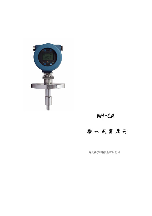
MJSV-10PI003中文资料
- 格式:pdf
- 大小:243.08 KB
- 文档页数:5

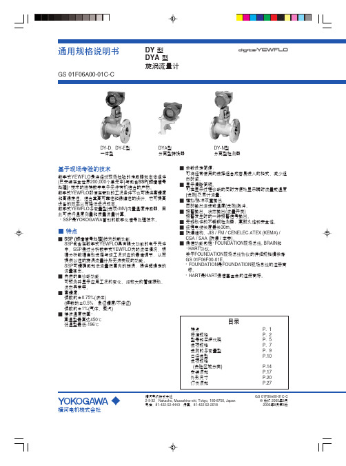
手持式示波器THS3000系列产品技术资料主要特点和优点主要性能指标100 MHz或200 MHz带宽型号高达5 GS/s的最大采样率,200 ps分辨率4条全面隔离的浮动通道600 V RMS CAT III, 1000 V RMS CAT II等级输入(BNC到接地)测量和分析21种自动测量波形数学运算和FFT频谱分析电压、时间、频率、功率光标测量应用功能TrendPlot TM记录测量数据波形通过/失败极限测试100屏自动显示屏记录程序易用功能6英寸(153 mm)明亮的彩色显示器USB设备端口和主控端口电池可连续工作7个小时应用嵌入式模拟和数字设计电源器件、电源电子和电源设计汽车和航空设计和维护工用设备设计和安装现场测试和服务产品技术资料4条隔离输入通道,简便地处理任何类型的混合信号输入。
便于携带,处理挑战性环境THS3000手持式示波器系列重量轻,拥有4条隔离通道,电池可连续工作长达7个小时,能够安全地在工作台或在现场进行浮动测量或差分测量。
现在,您可以获得预期泰克提供的优异性能,安全经济地处理棘手的环境。
准确地测量信号THS3000手持式示波器拥有高达200 MHz的带宽、4条通道和5 GS/s的最大采样率,没有任何其它示波器能够在这样一台便携式仪器中,提供如此高的带宽和采样率。
THS3000手持式示波器系列每条通道提供了10,000点的记录长度,可以以更高的采样率捕获更多的信号信息,清楚地查看信号细节。
对必需测量在长时间内变化的低速信号的应用,THS3000系列提供了滚动模式,把记录长度扩展到30,000点信号信息。
安全地进行浮动测量和差分测量在电源电子、电源半导体和其它电子应用上进行准确安全的测量,在信号参考点浮动或没有参考接地时可能极具挑战性。
在信号覆盖从低压到高压(kV)范围或必须使用保护技术,可能产生地面环路时,问题会变得非常复杂。
为实现浮动测量,THS3000系列在结构上不同于其它大多数示波器。

SMIV 系列电压变送器南京三盟科技有限公司NanJing SanMeng Science and Technology Co. , Ltd. MSN : tech@ 技术支持:025-********,159******** QQ: 1492884320, 892210045网址:, Email:nj_sanmeng@ ,nj_sanmeng@ ,sale@ SMIV 系列电压变送器说明书目 录SMIVxxAC 系列单相标准导轨型交流电压变送器............................................................................2 SMIV3-xxAC/Dn 系列3相组合交流电压变送器...........................................................................3 SMIVxxDC/Dn 系列标准导轨型直流电压变送器............................................................................4 其他外形电压变送器.............................................................................................................................5 SMIV-EF 系列真有效值电压变送器-适合整流器、变频器及高频和低频电压测量....................5 直流均值电压变送器.............................................................................................................................5 双输出电压变送器.................................................................................................................................6 小体积电压变送器(也适合PCB 安装).................................................................................................6 Dn 导轨式变送器外形尺寸选型.. (7)SMIVxxAC 系列单相交流电压变送器南京三盟科技有限公司NanJing SanMeng Science and Technology Co. , Ltd. MSN : tech@技术支持:025-********,159******** QQ: 1492884320, 892210045网址:, Email:nj_sanmeng@ ,nj_sanmeng@ ,sale@ SMIVxxAC 系列单相标准导轨型交流电压变送器选型举例(标准量程有50mV,1V,10V ,110V,300V,500V,690V,800V,1200V ,2KV,5KV,8KV,10KV,15KV,20KV等)名称型号额定测量 电压(V)AC供电电压(Vdd) ±10% 输出 负载RL测量阻值 最小值/ 最大值ohms*工作温度SMIVxxACE-Pn-On/Dn xx Pn On 电流输出时:100/300 电压输出时:>100k SMIV110ACE-P4-O1/D22 0-110 220V AC 4-20mA 100/300 SMIV300ACE-P1-O1/D22 0-300 24V DC 4-20mA 100/300交流电压变送器SMIV1200ACE-P2-O2/D220-120012V DC0-20mA100/300E:-20℃— 70℃ L:-40℃— 85℃*当负载电阻超出最大到最小负载电阻范围时,变送器不会损坏;所示电阻值均为峰值电流条件。
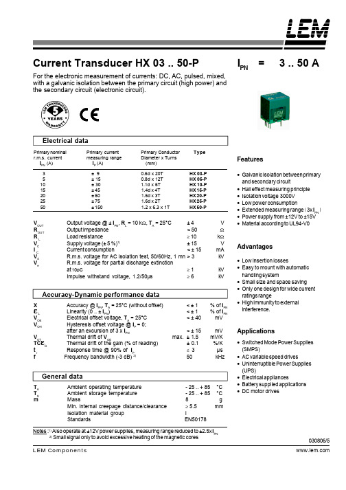
Electrical data Primary nominal Primary currentPrimary Conductor Typer.m.s. current measuring range Diameter x Turns I PN (A) I P (A) (mm)3± 90.6d x 20T HX 03-P5± 15 0.8d x 12T HX 05-P 10± 30 1.1d x 6T HX 10-P 15± 45 1.4d x 4T HX 15-P 20± 60 1.6d x 3T HX 20-P 25± 75 1.6d x 2THX 25-P 50± 1501.2 x 6.3 x 1THX 50-PV OUT Output voltage @ ± I PN , R L = 10 k Ω, T A = 25°C ± 4 V R OUT Output impedance < 50ΩR L Load resistance≥ 10k ΩVC Supply voltage (± 5 %)1)± 15 V I C Current consumption< ± 15 mA V d R.m.s. voltage for AC isolation test, 50/60Hz, 1 mn > 3kV V eR.m.s. voltage for partial discharge extinction at 10pC≥ 1kV Impulse withstand voltage, 1.2/50µs≥ 6kVAccuracy-Dynamic performance dataXAccuracy @ I PN , T A = 25°C (without offset) < ± 1% of I PNεL Linearity (0 .. ± I PN ) < ± 1% of I PN V OE Electrical offset voltage, T A = 25°C < ± 40mV V OH Hysteresis offset voltage @ I P = 0;after an excursion of 3 x I PN < ± 15mVV OT Thermal drift of V OE max. ± 1.5mV/K TC εG Thermal drift of the gain (% of reading) ± 0.1%/K t r Response time @ 90% of I P ≤ 3µsf Frequency bandwidth (-3 dB) 2) 50 kHz General dataT A Ambient operating temperature - 25 .. + 85°C T S Ambient storage temperature - 25 .. + 85°C mMass8g Min. internal creepage distance/clearance ≥ 5.5 mm Isolation material group IStandardsEN50178Current Transducer HX 03 .. 50-PFor the electronic measurement of currents: DC, AC, pulsed, mixed,with a galvanic isolation between the primary circuit (high power) and the secondary circuit (electronic circuit).I PN =3 .. 50 ANotes :1) Also operate at ±12V power supplies, measuring range reduced to ±2.5x I PN2)Small signal only to avoid excessive heating of the magnetic cores030806/5Features•Galvanic isolation between primary and secondary circuit•Hall effect measuring principle •Isolation voltage 3000V •Low power consumption•Extended measuring range (3x I PN )•Power supply from ±12V to ±15V •Material according to UL94-V0Advantages•Low insertion losses•Easy to mount with automatichandling system•Small size and space saving •Only one design for wide current ratings range•High immunity to external interference.Applications•Switched Mode Power Supplies (SMPS)•AC variable speed drives•Uninterruptible Power Supplies (UPS)•Electrical appliances•Battery supplied applications •DC motor drivesLEM Components。

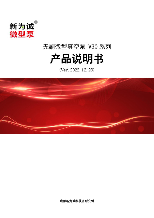
无刷微型真空泵V30系列产品说明书(Ver.2022.12.23)1产品版本及外观1.1V30(基础型)1.2V30(旋钮调速型)1.3V30(频率调速型)1.4V30(ding配型)2技术参数2.1关键参数注:1、该系列微型泵均使用直流电源,输入电压要求:DC24V±10%(24V型号泵)、DC12V±10%(12V型号泵);所需直流稳压电源为选配件,客户需自配,或也可从我司购买定做好的电源。
2、如无特别说明,技术参数均是在25℃、标准大气压101kPa的条件下的测定值;3、表中参数是在电机MAX转速时测得。
当转速变化时,压力/真空度基本不变;4、表中参数均在标配接口下测得,若选配其他类型接口,参数可能会发生小幅改变;5、表中峰值流量是指用玻璃转子流量计(去掉了针型阀)测得的流量值,平均流量是用皂膜流量计测得的流量值;不建议使用质量流量计进行测量,因原理等原因会导致较大误差(这不是微型泵的问题)。
6、该系列微型泵根据:(1)流量不同可分为:大流量-L,中流量-M,小流量-S;(2)性能、寿命、生产工艺、调试等不同,可分为简化版(简称J,下同)、标准版(B)、品质版(P);(3)功能不同,可细分为基础型(J)、旋钮调速型(X)、频率调速型(H)、ding配型(D);结合版本组合为:简化版-基础型(JJ)、标准版-旋钮调速型(BX)、标准版-频率调速型(BH)、品质版-旋钮调速型(PX)、品质版频率调速型(PH)、品质版-ding配型(PD)。
(4)是否可定做不同材质:①型号中带有后缀“B”的,可定做耐腐蚀材质(隔膜/单向阀材质:FKM(氟橡胶));②无后缀的,默认为:隔膜/单向阀材质:EPDM。
(4)【实例】(订购时,请一定注明流量、版本后缀!):①V30M-JJ-24V,意为V30微型真空泵中,中流量、简化版-基础型,DC24V供电;②V30S-PD-24V,意为V30微型真空泵中,小流量、品质版-ding配型,DC24V供电,品质MAX高,功能MAX齐全产品。

JWB系列矿用无极绳调速机械绞车使用说明书(行星差速,同轴布置)(液控或手动操作)(重锤或液压张紧)执行标准MT/T885-2000及Q/GX008-2008邹城市广信科技开发有限责任公司2010年04月目录1.概述 (1)用途及适用范围 (1)使用环境条件与环境影响 (1)产品特点 (1)型号组成及其代表意义 (2)2.技术特征 (2)主要技术参数 (2)主要性能 (2)3.主要结构及工作原理 (3)绞车主机 (3)梭车 (3)尾轮 (3)主压绳轮组 (4)副压绳轮组 (4)托绳轮组 (4)拐弯轮组 (4)液压系统 (4)控制与显示 (4)4.安装与调试 (4)设备安装的条件与技术要求 (5)安装方法及注意事项 (5)电气系统安装及调试 (7)试运行及注意事项 (7)5.绞车控制步骤 (8)6.使用及维护 (8)7.故障分析与排除 (9)8.运输、储存 (10)9.开箱与检查 (10)10.其他 (10)11.配件一览表 (11)12.附图 (15)13.联系地址及电话………………………………………………(封底)1.概述用途及适用范围本产品是以钢丝绳牵引的轨道运输设备,主要用于井下工作面顺槽和采区大巷实现材料、设备运输,特别适用于大型综采设备的运输牵引和长运距及材料的运输,能大大提高运输效率及运输安全可靠性,也可用于金属矿山和地面轨道运输,可适用于坡度不大于30℃或弯曲、起伏变化的轨道运输。
特别提示:本绞车严禁运行中双工作闸同时制动。
使用环境条件与环境影响牵引绞车可在煤矿井下有瓦斯的巷道中使用;牵引绞车应安置于环境温度为10℃—40℃,环境相对湿度不超过85%(+25℃),海拔高度不超过1000m的巷道内工作。
对于海拔高度超过1000m时,需要考虑到空气冷却作用和介电强度的下降,选用的电器设备应根据制造厂和用户的协议进行设计或使用;牵引绞车在有隔爆要求的巷道内工作时,必须选用在有效期内、有煤安标志的隔爆型电机及电气,且工作时周围空气中的甲烷、煤尘、硫化氢、二氧化碳等不得超过《煤矿安全规程》中所规定的安全含量;牵引绞车无任何污染,不影响周围环境;产品特点本设备吸收借鉴了绳牵引卡轨车的成熟技术,采用了调度绞车的行星轮减速、变速方式,具有如下特点:绞车采用了三级行星轮系减速传动,电机输入轴直接传动常啮合的行星差速器,在快速、慢速块式制动闸的相应结合下,形成零速、快速和慢速,最后传动末级行星轮系和摩擦滚筒。
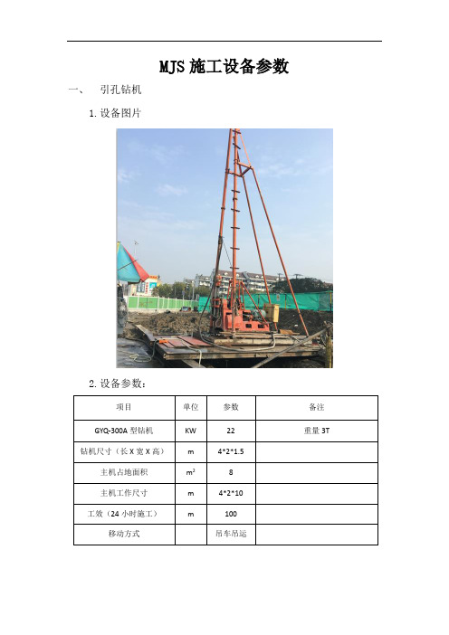

DescriptionThis family of SMT LEDs is packaged in the industry standard PLCC-2 package. These SMT LEDs have high reliability performance and are designed to work under a wide range of environmental conditions. This high reliability feature makes them ideally suited to be used under harsh interior automotive as well as interior signs application conditions.To facilitate easy pick & place assembly, the LEDs are packed in EIA-compliant tape and reel. Every reel will be shipped in single intensity and color bin, except red color, to provide close uniformity.These LEDs are compatible with IR solder reflow process. Due to the high reliability feature of these products, they can also be mounted using through-the-wave soldering process.The super wide viewing angle at 120˚ makes these LEDs ideally suited for panel, push button, or general backlighting in automotive interior, office equipment, industrial equipment, and home appliances. The flat top emitting surface makes it easy for these LEDs to mate with light pipes. With the built-in reflector pushing up the intensity of the light output, these LEDs are also suitable to be used as LED pixels in interior elec-tronic signs.Features• Industry standard PLCC-2 package • High reliability LED package• High brightness using AlInGaP and InGaN dice tech-nologies • Available in full selection of colors • Super wide viewing angle at 120˚• Available in 8 mm carrier tape on 7 inch reel (2000 pieces)• Compatible with both IR and TTW soldering processApplications• Interior automotive– Instrument panel backlighting – Central console backlighting – Cabin backlighting • Electronic signs and signals – Interior full color sign – Variable message sign• Office automation, home appliances, industrial equipment– Front panel backlighting – Push button backlighting – Display backlightingHSMx-A10x-xxxxx PLCC-2Surface Mount LED IndicatorData SheetCAUTION: HSMN,M,K and E-A10x-xxxxx LEDs are Class 2 ESD sensitive. Please observe appropriate precau-tions during handling and processing. Refer to Avago Application Note AN-1142 for additional details.Package Dimensions(ANODE MARKING FOR AlGaAs DEVICES)TOP MOUNTREVERSE MOUNTNOTE: ALL DIMENSIONS IN MILLIMETERS.Device Selection GuideRedPart Number Min. Iv (mcd) Typ. Iv (mcd) Max. Iv (mcd) Test Current (mA) Dice Technology HSMS-A100-J00J1 4.0 15.0 - 20 GaP HSMS-A100-L00J1 10.0 15.0 - 20 GaP HSMS-A100-H70J2 .0 - 8.0 10 GaP HSMS-A100-J80J2 5.0 - 15.5 10 GaP HSMH-A100-L00J1 10.0 15.0 - 20 AlGaAs HSMH-A100-N00J1 25.0 50.0 - 20 AlGaAs HSMH-A100-L70J2 12.5 - 2.0 10 AlGaAs HSMH-A100-M80J2 20.0 - 62.0 10 AlGaAs HSMH-A100-P 0J1 40.0 - 100.0 20 AlGaAs HSMC-A100-J00J1 4.0 100.0 - 20 AlInGaP HSMC-A100-Q00J1 6 .0 100.0 - 20 AlInGaP HSMC-A100-R00J1 100.0 140.0 - 20 AlInGaP HSMC-A101-S00J1 160.0 220.0 - 20 AlInGaP HSMZ-A100-T00J1 250.0 50.0 - 20 AlInGaP HSMC-A100-P 0J1 40.0 - 100.0 20 AlInGaP HSMC-A101-R80J1 125.0 - 95.0 20 AlInGaP HSMZ-A100-S80J1 200.0 - 620.0 20 AlInGaPRed OrangePart Number Min. Iv (mcd) Typ. Iv (mcd) Max. Iv (mcd) Test Current (mA) Dice Technology HSMJ-A100-Q00J1 6 .0 100.0 - 20 AlInGaP HSMJ-A101-S00J1 160.0 200.0 - 20 AlInGaP HSMV-A100-T00J1 250.0 50.0 - 20 AlInGaP HSMJ-A100-Q 0J1 6 .0 - 155.0 20 AlInGaP HSMJ-A100-R40J1 100.0 - 15.0 20 AlInGaP HSMJ-A101-R80J1 125.0 - 95.0 20 AlInGaP HSMV-A100-S80J1 200.0 - 620.0 20 AlInGaPOrangePart Number Min. Iv (mcd) Typ. Iv (mcd) Max. Iv (mcd) Test Current (mA) Dice Technology HSMD-A100-J00J1 4.0 15.0 - 20 GaP HSMD-A100-L00J1 10.0 15.0 - 20 GaP HSMD-A100-J7PJ2 5.0 - 12.5 10 GaP HSMD-A100-K4PJ2 6. - 20.0 10 GaPHSML-A100-Q00J1 6 .0 100.0 - 20 AlInGaP HSML-A101-S00J1 160.0 220.0 - 20 AlInGaP HSML-A100-Q7PJ1 80.0 - 200.0 20 AlInGaP HSML-A100-R7PJ1 125.0 - 15.0 20 AlInGaP HSML-A101-R8WJ1 125.0 - 95.0 20 AlInGaPDevice Selection Guide, continuedYellow/AmberPart Number Min. Iv (mcd) Typ. Iv (mcd) Max. Iv (mcd) Test Current (mA) Dice Technology HSMY-A100-J00J1 4.0 12.0 - 20 GaP HSMY-A100-L00J1 10.0 12.0 - 20 GaP HSMY-A100-J 5J2 4.0 - 10.0 10 GaP HSMY-A100-K45J2 6. - 20.0 10 GaP HSMA-A100-Q00J1 6 .0 100.0 - 20 AlInGaP HSMA-A101-S00J1 160.0 220.0 - 20 AlInGaP HSMU-A100-S00J1 160.0 20.0 - 20 AlInGaP HSMA-A100-Q 5J1 6 .0 - 155.0 20 AlInGaP HSMA-A100-R45J1 100.0 - 15.0 20 AlInGaP HSMA-A101-R8WJ1 125.0 - 95.0 20 AlInGaP HSMU-A100-S4WJ1 160.0 - 500.0 20 AlInGaPYellow GreenPart Number Min. Iv (mcd) Typ. Iv (mcd) Max. Iv (mcd) Test Current (mA) Dice Technology HSMG-A100-J02J1 4.0 18.0 - 20 GaP HSMG-A100-K72J2 8.0 - 20.0 10 GaP HSME-A100-M02J1 16.0 70.0 - 20 AlInGaP HSME-A100-N82J1 0.0 - 100.0 20 AlInGaPEmerald GreenPart Number Min. Iv (mcd) Typ. Iv (mcd) Max. Iv (mcd) Test Current (mA) Dice Technology HSMG-A100-H01J1 2.5 8.0 - 20 GaP HSMG-A100-G 1J2 1.6 - 4.0 10 GaP HSMG-A100-H41J2 2.5 - 8.0 10 GaP HSME-A100-L01J1 10.0 40.0 - 20 AlInGaP HSME-A100-M PJ1 16.0 - 40.0 20 AlInGaPGreenPart Number Min. Iv (mcd) Typ. Iv (mcd) Max. Iv (mcd) Test Current (mA) Dice Technology HSMM-A101-R00J1 100.0 200.0 - 20 InGaN HSMM-A100-S00J1 160.0 50.0 - 20 InGaN HSMM-A101-Q7PJ1 80.0 - 200.0 20 InGaN HSMM-A101-R7PJ1 125.0 - 15.0 20 InGaN HSMM-A101-R8PJ1 125.0 - 95.0 20 InGaN HSMM-A100-S8PJ1 200.0 - 620.0 20 InGaNDevice Selection Guide, continuedCyanPart Number Min. Iv (mcd) Typ. Iv (mcd) Max. Iv (mcd) Test Current (mA) Dice Technology HSMK-A101-R00J1 100.0 170.0 - 20 InGaNHSMK-A100-S00J1 160.0 280.0 - 20 InGaNHSMK-A100-S8WJ1 200.0 - 620.0 20 InGaNHSMK-A101-Q WJ1 6 .0 - 155.0 20 InGaNHSMK-A101-R4WJ1 100.0 - 15.0 20 InGaNBluePart Number Min. Iv (mcd) Typ. Iv (mcd) Max. Iv (mcd) Test Current (mA) Dice Technology HSMB-A100-J00J1 4.0 15.0 - 20 GaNHSMB-A100-J70J2 5.0 - 12.5 10 GaNHSMB-A100-K80J2 8.0 - 25.0 10 GaNHSMN-A101-N00J1 25.0 50.0 - 20 InGaNHSMN-A100-P00J1 40.0 70.0 - 20 InGaNHSMN-A101-N7YJ1 0.0 - 80.0 20 InGaNHSMN-A100-P8YJ1 50.0 - 155.0 20 InGaNNote:1. The luminous intensity, I v, is measured at the mechanical axis of the lamp package. The actual peak of the spatial radiation pattern may not be aligned with this axis.Part Numbering SystemHSM x1 - A x2 x x4 -x5x6 x7 x8x9Packaging OptionColor Bin SelectionIntensity Bin SelectDevice Specific ConfigurationPackage TypeLED Chip ColorAbsolute Maximum Ratings (T A = 25°C)Parameters HSMS/D/Y/G HSMH HSMC/J/L/A HSME HSMZ/V/U HSMM/K/B/N DC Forward Current[1] 0 mA 0 mA 0 mA[ ,4]20 mA[4] 0 mA[ ,4] 0 mA Peak Forward Current[2]100 mA 100 mA 100 mA 100 mA 100 mA 100 mA Power Dissipation 6 mW 60 mW 6 mW 48 mW 72 mW 114 mW Reverse Voltage 5 VJunction Temperature 110°COperating Temperature –55°C to +100°CStorage Temperature –55°C to +100°CNotes:1. Derate linearly as shown in Figure 4.2. Duty factor = 10%, Frequency = 1 kHz.. Drive current between 10 mA and 0 mA is recommended for best long term performance.4. Operation at current below 5 mA is not recommended.Electrical Characteristics (T A = 25˚C) Forward Voltage Reverse Voltage Reverse Voltage ThermalV F (Volts) @ I F = 20 mA V R @ 100 µA V R @ 10 µA Resistance Part Number Typ. Max. Min. Min. R θJP (°C/W)HSMS/D/Y/G 2.2 2.6 5 — 180HSMH 1.9 2.6 5 — 180HSMC/J/L/A/E 1.9 2.4 5 — 280HSMZ/V/U 2.2 2.6 5 — 280HSMB .9 4. — 5 280HSMM/K/N .44.05—5280Optical Characteristics (T A = 25˚C)ViewingLuminous PeakDominant Angle Luminous Intensity/ Wavelength Wavelength [1] 2 θ1/2[2] Efficacy ηv [3] Total FluxDiceλPEAK (nm) λD (nm) (Degrees) (lm/W) I v (mcd)/Φv (mlm) Color Part Number Technology Typ. Typ. Typ. Typ. Typ.Red HSMS-A100 GaP 6 5 626 120 120 0.45 HSMH-A100 AlGaAs 645 6 7 120 6 0.45 HSMC-A10x AlInGaP 6 5 626 120 150 0.45 HSMZ-A100 AlInGaP 6 9 6 0 120 155 0.45Red HSMJ-A10x AlInGaP 621 615 120 240 0.45OrangeHSMV-A100 AlInGaP 62 617 120 26 0.45Orange HSMD-A100 GaP 600 602 120 80 0.45 HSML-A10x AlInGaP 609 605 120 20 0.45Amber HSMY-A100 GaP 58 585 120 520 0.45 HSMA-A10x AlInGaP 592 590 120 480 0.45 HSMU-A100 AlInGaP 594 592 120 500 0.45Yellow HSMG-A100 GaP 565 569 120 590 0.45Green HSME-A100 AlInGaP 575 570 120 560 0.45Emerald HSMG-A100 GaP 558 560 120 650 0.45GreenHSME-A100 AlInGaP 566 560 120 610 0.45Green HSMM-A10x InGaN 52 525 120 500 0.45Cyan HSMK-A10x InGaN 502 505 120 00 0.45Blue HSMB-A100 GaN 428 462 120 65 0.45HSMN-A10xInGaN468470120750.45Notes:1. The dominant wavelength, λD , is derived from the CIE Chromaticity Diagram and represents the color of the device.2. θ1/2 is the off-axis angle where the luminous intensity is 1/2 the peak intensity.. Radiant intensity, I e in watts/steradian, may be calculated from the equation I e = I v /ηv , where I v is the luminous intensity in candelas and ηv is the luminous efficacy in lumens/watt.Figure 1. Relative intensity vs. wavelength.Figure 2. Forward current vs. forward voltage.Figure 3. Relative intensity vs. forward current.Figure 4. Maximum forward current vs. ambient temperature. Derated based on T J MAX = 110˚C, RθJA= 500˚C/W.Figure 5. Dominant wavelength vs. forwardcurrent – InGaN devices.FORWARD VOLTAGE – V103035 F O R W A R D C U R R E N T – m A5201525Figure 4b. Maximum Forward Current Vs. Solder Point Temperature. Derated based on T J MAX = 110°C, RθJP= 180°C/W or 280°C/W.101520253035TEMPERATURE (°C)C U R R E N T - mA5101520253035TEMPERATURE (°C)C U R R E N T - m ACURRENT – mA460480540 D O M I N A N T W A V E L E N G T H – n mHSMx-A100 fig 5500470510490520530Figure 8a. Recommended SnPb reflow soldering profile.Figure 7. Radiation Pattern.D E L T A V F (N O R M A L I Z E D A T 25°C )-0.3TEMPERATURE – °C0.50.40.20.10-0.2-0.10.3Figure 6. Forward voltage shift vs. temperature.Figure 8b. Recommended Pb-free reflow soldering profile.(Acc. to J-STD-020C)TIMET E M P E R A T U R ET E M P E R A T U R E – °CNote: For detail information on reflow soldering of Avago surfaceFigure 11. Tape leader and trailer dimensions.Figure 12. Tape dimensions.Figure 13. Reel dimensions.Figure 14. Reeling orientation.11Intensity Bin Select (X5X6) Individual reel will contain parts from one half bin only.X5Min I v BinX60 Full Distributionhalf bins starting from X514 4 half bins starting from X515 5 half bins starting from X517 half bins starting from X528 4 half bins starting from X529 5 half bins starting from X52 Intensity Bin LimitsBin ID Min. (mcd) Max. (mcd) G1 1.80 2.24G2 2.24 2.80H1 2.80 .55H2 .55 4.50J1 4.50 5.60J2 5.60 7.20K1 7.20 9.00K2 9.00 11.20L1 11.20 14.00L2 14.00 18.00M1 18.00 22.40M2 22.40 28.50N1 28.50 5.50N2 5.50 45.00P1 45.00 56.00P2 56.00 71.50Q1 71.50 90.00Q2 90.00 112.50 R1 112.50 140.00 R2 140.00 180.00 S1 180.00 224.00 S2 224.00 285.00 T1 285.00 55.00 T2 55.00 450.00 U1 450.00 560.00 U2 560.00 715.00 V1 715.00 900.00 V2 900.00 1125.00 Tolerance of each bin limit = ± 12%.Color Bin Select (X7)Individual reel will contain partsfrom one full bin only.X70 Full DistributionZ A and B onlyY B and C onlyW C and D onlyV D and E onlyU E and F onlyT F and G onlyS G and H onlyQ A, B, and C onlyP B, C, and D onlyN C, D, and E onlyM D, E, and F onlyL E, F, and G onlyK F, G, and H only1 A, B, C, and D only2 E, F, G, and H onlyB, C, D, and E only4 C, D, E, and F only5 A, B, C, D, and E only6 B, C, D, E, and F onlyColor Bin LimitsBlue Min. (nm) Max. (nm)A 460.0 465.0B 465.0 470.0C 470.0 475.0D 475.0 480.0Green Min. (nm) Max. (nm)A 515.0 520.0B 520.0 525.0C 525.0 5 0.0D 5 0.0 5 5.0Cyan Min. (nm) Max. (nm)A 490.0 495.0B 495.0 500.0C 500.0 505.0D 505.0 510.0Color Bin LimitsEmeraldGreen Min. (nm) Max. (nm)A 552.5 555.5B 555.5 558.5C 558.5 561.5D 561.5 564.5Orange Min. (nm) Max. (nm)A 597.0 600.0B 600.0 60 .0C 60 .0 606.0D 606.0 609.0E 609.0 612.0Red Orange Min. (nm) Max. (nm)A 611.0 616.0B 616.0 620.0Red Min. (nm) Max. (nm)Full DistributionTolerance of each bin limit = ± 1 nm.Amber Min. (nm) Max. (nm)A 582.0 584.5B 584.5 587.0C 587.0 589.5D 589.5 592.0E 592.0 594.5F 594.5 597.0YellowGreen Min. (nm) Max. (nm)E 564.5 567.5F 567.5 570.5G 570.5 57 .5H 57 .5 576.512Packaging Option (X 8X 9)Option Test Current Package Type Reel Size J1 20 mA Top Mount 7 inch J4 20 mA Top Mount 1 inch H1 20 mA Reverse Mount 7 inch H4 20 mA Reverse Mount 1 inch J2 10 mA Top Mount 7 inch J5 10 mA Top Mount 1 inch H2 10 mA Reverse Mount 7 inch H5 10 mA Reverse Mount1 inchFor product information and a complete list of distributors, please go to our website: Avago, Avago Technologies, and the A logo are trademarks of Avago Technologies Limited in the United States and other countries.Data subject to change. Copyright © 2007 Avago Technologies Limited. All rights reserved. Obsoletes AV01-0040EN AV02-0198EN - May 30, 2007Moisture SensitivityThis product is qualified as Moisture Sensitive Level 2a per Jedec J-STD-020. Precautions when handling this moisture sensitive product is important to ensure the reliability of the product. Do refer to Avago Application Note AN5 05 Handling of Moisture Sensitive Surface Mount Devices for details.A. Storage before use- Unopen moisture barrier bag (MBB) can be stored at <40°C/90%RH for 12 months. If the actual shelf life has exceeded 12 months and the HIC indicates that baking is not required, then it is safe to reflow the LEDs per the original MSL rating.- It is not recommended to open the MBB prior to assembly (e.g. for IQC).B. Control after opening the MBB- The humidity indicator card (HIC) shall be read im-mediately upon opening of MBB.- The LEDs must be kept at < 0°C / 60%RH at all time and all high temperature related process including soldering, curing or rework need to be completed within 672 hours.C. Control for unfinished reel- For any unuse LEDs, they need to be stored in sealed MBB with desiccant or desiccator at <5%RH.D. Control of assembled boards- If the PCB soldered with the LEDs is to be subjected to other high temperature processes, the PCB need to be stored in sealed MBB with desiccant or desic-cator at <5%RH to ensure no LEDs have exceeded their floor life of 672 hours.E. Baking is required if:- “10%” or “15%” HIC indicator turns pink.- The LEDs are exposed to condition of > 0°C / 60% RH at any time.- The LEDs floor life exceeded 672 hours.Recommended baking condition: 60±5°C for 20 hours.。
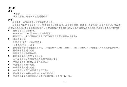
第一章简介警告使用仪器前,请仔细阅读使用说明书。
概述本仪器是一台智能型多功能接地电阻测试仪。
本仪器采用数字信号处理技术,直接提取接地测量信号,具有高分辨率、高精度、很好的抗干扰能力等特点,可准确测量接地电阻值。
本仪器能执行标准的三极和四极接地电阻测量以外,还具有两极接地电阻测量和计算土壤电阻率的功能。
●设计符合以下安全标准:IEC61010-1(CAT Ⅲ 600V、污染等级Ⅱ)IEC61557-1、5(交流1000V和直流1500V以下低压配电系统电气安全)●基本测量功能2极/3极/4极法接地电阻测量土壤电阻率(ρ)测量●接地电阻测量采用交流激励测试,4种测试频率(94Hz、105Hz、111Hz、128Hz),可手动选择,从而减低干扰源影响。
●辅助接地电阻测试功能测试并显示辅助接地电阻。
●辅助接地电阻上限警告显示功能由于辅助接地电阻高而可能无确测试时显示警告。
●电阻测量中自动量程,超量程显示OL。
●干扰电压过高指示功能。
●串联干扰电压测试功能。
●白色背光功能便于在阴暗光线下工作。
●可去除测试线的剩余电阻(Rk)的设定功能。
●可设定土壤电阻率测试时的辅助接地棒间隔,设置围:1m~30m。
●具有可设定时间的自动背光关闭和自动电源关闭功能。
●操作方便的数据记录功能、查询记录数据,部存储器可独立存储100个(组)测量数据。
●小巧、坚固的结构设计,便于双手作业的颈带,简便的人机操作,适应现场运输和恶劣的环境。
开箱检查检查货物,查看它在运送途中是否受损。
检查货物是否齐全,并保存包装材料以供以后运送使用。
本仪器所提供的标配附件和选购附件列在下面。
选购附件可以根据需要购买。
标配附件•测试导线6m(黑色)1条•测试导线6m(绿色)1条•测试导线15m(红色)1条•测试导线30m(蓝色)1条•辅助接地棒 4个•使用说明书1本•碱性电池1.5V(LR6)8节•软携带包:C安全警告本仪器的设计、制造和检测均达到IEC61010-1、IEC61557-1、IEC61557-5安全标准要求,本手册包括确保仪器的安全使用及保证仪器的安全状态,使用者所必须遵守的警告和安全条例。
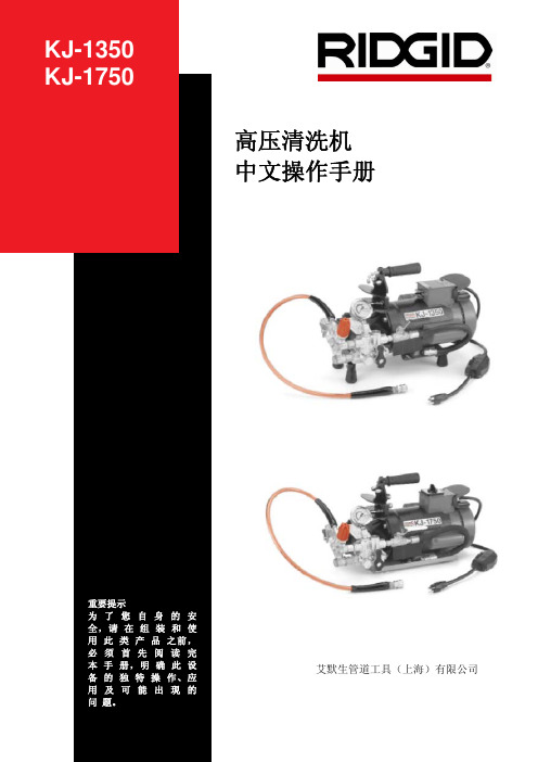
高压清洗机中文操作手册艾默生管道工具(上海)有限公司目录机器型号和序列号记录表格 (3)安全须知 (4)工作场所安全注意事项 (4)用电安全 (4)个人安全注意事项 (5)工具的使用与保养 (5)服务 (5)其它安全注意事项高压清洗机的使用安全 (6)产品概述、技术参数与标准配置产品概述 (6)技术参数 (6)标准配置 (7)喷嘴和软管 (8)附件 (9)机器组装泵的使用指南 (9)小车 (9)机器检查 (10)机器和工作区域设置 (10)喷嘴选型表 (12)软管选型表 (12)操作步骤启动和压力调整 (13)脉冲控制阀 (14)正常模式 (14)脉冲模式,用于通过弯头和存水弯 (15)通过弯头方法介绍 (15)打通堵塞 (15)高压喷射清洁管道 (16)高压清洗套装 (16)清洗操作 (16)附件喷嘴和软管 (16)其它附件 (17)H-5迷你软管卷 (17)保养指导入口过滤器清洗 (17)喷嘴清洗 (18)高压清洗机清洗 (18)防冻措施 (18)机器存放要求 (18)维修与服务 (18)故障诊断 (19)线路图 (19)终身质保条款........................................................................................................................封底KJ-1350&KJ-1750型高压清洗机KJ-1350&KJ-1750型高压清洗机在下面空格内记下产品序列号,并妥善保存写有产品序列号的铭牌。
序列号安全须知警告!请仔细阅读所有的安全注意事项和安全指导。
如果不遵从这些安全指导可能会导致电击、火灾或者严重人身伤害。
请妥善保存本安全注意事项和安全指导。
工作场所安全注意事项1. 保持工作场所干净整洁和照明充分。
混乱和昏暗的环境容易引起安全事故的发生。
要防止火灾的发生。
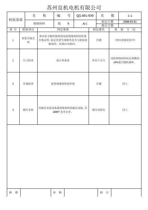

技术说明书(版本:)项目名称:项目编号:产品名称:文件编号:编制:工艺:标准化:批准:浙江威星智能仪表股份有限公司年月日文档修改记录目录1.概述 (4)2.工作原理 (4)3.基本功能和应用功能 (4)3.1.表具终端基本功能 (4)3.1.1.取信方式 (4)3.1.2.通信功能 (4)3.1.3.时钟功能 (4)3.1.4.液晶显示 (4)3.1.5.蜂鸣提示功能 (5)3.1.6.电源电压检测功能 (5)3.1.7.阀门控制功能 (5)3.1.8.存储功能 (5)3.2.表具终端应用功能 (5)3.2.1.膜式基表配型 (5)3.2.2.超声波基表配型 (6)3.3.中间设备基本功能 (6)3.3.1.中继器 (6)3.3.2.集中器 (6)3.3.3.移动采集器 (7)4.产品性能参数 (8)5.产品外形尺寸 (10)6.硬件说明 (10)6.1.硬件电路结构 (10)6.2.裸板检测要求 (10)6.3.技术参数指标 (10)6.4.产品出厂条码要求 (11)7.软件说明 (11)7.1.程序文件名称及版本 (11)7.2.程序烧录 (11)8.使用和操作 (11)8.1.正确使用产品的操作程序 (11)8.2.操作时的注意事项 (11)8.3.故障提示(包括异常和错误代码) (11)9.故障分析与排除 (11)10.产品默认出厂状态和配置项 (12)本文蓝色字体是要点提示或是举例说明,正式提交的文档请根据实际产品说明每个要点,并删除蓝色字体。
1.概述说明产品整体的主要应用功能,以及产品组成。
说明本产品在系统中的主要作用。
2.工作原理说明产品实现关键功能的基本原理,过于复杂的可配图说明。
3.基本功能和应用功能不局限以下功能3.1. 表具终端基本功能3.1.1.取信方式说明使用的取信技术,以及配套实现的与取信相关的功能3.1.2.通信功能说明产品中使用的通讯方式,基本工作原理、步骤等。
3.1.3.时钟功能说明时钟功能的基本工作方式和应用方式3.1.4.液晶显示显示位数,配显示界面图及显示符号说明等3.1.5.蜂鸣提示功能说明各种响铃标志意义等3.1.6.电源电压检测功能提示电压检测判断依据等3.1.7.阀门控制功能说明阀门类型,优先级控制及恢复条件等3.1.8.存储功能说明数据存储内容以及各内容的存储数量3.2. 表具终端应用功能3.2.1.膜式基表配型不局限以下功能➢自动抄表➢即时抄表➢无卡预付费➢阶梯结算➢阀门控制➢数据冻结➢时间校准➢异常报警➢电池管理➢人机交互➢液晶显示、按键轮显➢手动按键开阀3.2.2.超声波基表配型不局限以下功能➢小流量泄漏预警➢超流量用气保护➢超声波计量故障报警3.3.中间设备基本功能3.3.1.中继器不局限以下功能➢通讯接口➢参数配置功能➢路由组网通信功能➢自主路由选择功能3.3.2.集中器功能不局限以下功能➢通讯接口➢主控板拨码配置功能➢通讯参数管理➢时钟管理➢集中器自动抄表日、抄表时➢集中器通讯地址➢频点管理➢集中器网络ID➢集中器无线空中速率➢集中器串口速率➢集中器网络数据删除➢组网节点管理➢组网与抄表➢USB转串口集中器调试查询➢指示灯➢自动抄表设定➢GPRS错误重启连接3.3.3.移动采集器功能不局限以下功能➢接口与功能➢指示灯4.产品性能参数产品性能参数指标根据具体产品设定膜式燃气表超声波配型中继器集中器移动采集器5.产品外形尺寸用以说明产品组成部门的外形尺寸、安装尺寸和主要参数,须配外形尺寸图说明。

NDJ系列粘度计是采用高细分驱动步进电机、16位微电脑处理器为核心的、数字式液晶带蓝色背光功能的数显粘度计。
仪器转速平稳、精确,按键标示明确,操作简便,程序化设计。
当扭矩低于20%(或10%)(以仪器报警界限为准)高于90%测量仪器会发出报警声。
屏幕直接显示粘度、转速、百分计标度、转子号以及所选用转子在当前转速下可测的最大粘度值。
主控板、细分驱动板全部采用贴片技术,电路设计采用目前最先进微电脑处理器,结构布局合理紧凑。
提供RS232接口,打印间隔可由用户自行设置。
该仪器满量程、各档线性度全部通过PC接口进行计量校正,其性能、功能达到国外同类型先进水平。
SNB系列粘度计是基于NDJ系列粘度计的升级产品。
除具备NDJ系列粘度计的性能、特点外,SNB系列粘度计的测量范围更广;转速选择改为全程无级变速;配置RTD温度探头实时监测粘度温度,精度可达0.1℃,温度测量范围为0℃-120℃;选配SNB数据采集和绘图软件通过PC接口进行全自动化数据采集,数据保存及历史数据对比等多项数理统计分析任务。
DV系列数字式粘度测量仪是世界上最通用粘度测量仪。
该仪器价廉物美深受客户欢迎,其功能、性能达到国外同类型产品先进水平。
除具备SNB系列粘度计的性能、特点外,还可进行精确剪切速率、剪切应力测量。
双向RS232接口,可与电脑通讯,实现程控和数据采集。
选购DV程控脱机下载软件将自定义的测量程序下载到仪器上实现自动化操作和个性化操作。
选购DV数据采集和程控分析软件实现电脑全自动化采集和分析流体流变特性曲线,另可实现数据保存,历史数据对比等功能。
NDJ系列、SNB系列、DV系列粘度计用于测量液体的粘性阻力即液体的动力粘度。
广泛应用于测定油脂、油漆、油墨、食品、涂料、造纸、化妆品、化工、胶囊、胶粘剂、胶水、精密陶瓷、树脂、牙膏、锂电池浆料及药物等各种流体的粘度。
1. 各仪器主要技术指标NDJ系列主要技术规格配小量样品适配器各系列量程SNB系列量程DV系列主要技术规格2. 数字式粘度计结构原理如图所示,以高细分驱动步进电机带动传感器指针,通过游丝和转轴带动转子旋转。
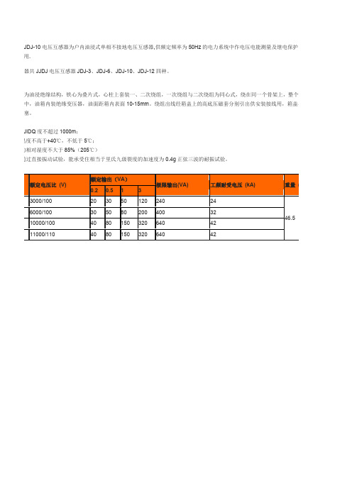
JDJ-10电压互感器为户内油浸式单相不接地电压互感器,供额定频率为50Hz的电力系统中作电压电能测量及继电保护用.
互感器共JJDJ电压互感器JDJ-3、JDJ-6、JDJ-10、JDJ-12四种。
感器为油浸绝缘结构,铁心为叠片式,心柱上套装一、二次绕组,一次绕组与二次绕组为同心式,绕在同一个骨架上,整个器身油箱中,油箱内装绝缘变压器,油面距箱内表面10-15mm。
绕组出线经箱盖上的高底压磁套分别引出供安装接线用,箱盖与油注油塞。
FUJIDQ度不超过1000m;
境温度不高于+40℃,不低于5℃;
气的相对湿度不大于85%(205℃)
已通过直接振动试验,能承受住相当于里氏九级裂度的加速度为0.4g正弦三波的耐振试验。
订货须知
订货时请提供以下参数:
产品型号。
额定电压比kV。
准确级组合及额定输出VA。
环境海拔高度m。
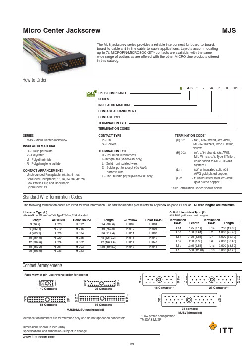
How to OrderThe MJS jackscrew series provides a reliable interconnect for board-to-board,board-to-cable and in-line cable-to-cable applications. Layouts accommodating up to 76 MICROPIN/MICROSOCKET TM contacts are available, with the samewide range of options as are offered with the other MICRO Line products offered in this catalog.SERIESINSULATOR MATERIAL CONTACT ARRANGEMENTCONTACT TYPE TERMINATION TYPE TERMINATION CODESSERIESCONTACT TYPE TERMINATION CODE*MJS26PH001*-TERMINATION TYPEINSULATOR MATERIAL B -Diallyl phthalate V -PolyesterU -PolyetherimideR -Polyphenylene sulfideMJS - Micro Center Jackscrew *See Termination Codes shown below.P -Pin S -Socket(H) 001 (H) 003(L) 1(L) 2-18" , 7/34 strand, #26 AWG,MIL-W-16878/4, Type E Teflon, yellow.-18", 7/34 strand, #26 AWG,MIL-W-16878/4, Type E Teflon, color coded to MIL-STD-681 System I.-1/2" uninsulated solid #25AWG gold plated copper.-1" uninsulated solid #25 AWGgold plated copper.H -Insulated wire harness.I -Integral tail (MJSV-28S only).L -Solid - uninsulated wire.S -Solder pot to accept #26 AWG harness wire.T -Thru bundle pigtail (MJSV-28P only).Unshrounded Receptacle: 10, 26, 51, 66Shrouded Receptacle; 10, 26, 34, 38, 42, 76Low Profile Plug and Receptacle (shrouded): 28CONTACT ARRANGEMENTSRoHS COMPLIANCE RStandard Wire Termination CodesThe following termination codes are listed for your information. For additional codes please refer to Appendix on page 79 and 81. All wire lengths are minimum.Harness Type (H)#26 A WG per MIL-W-16878/4 T ype E T eflon ,7/34 stranded.So li d U ninsulate d Type (L )#25A WG gold plated solid copper.L ength 3(76.2)6(152.4)8(203.2)10(254.0)12(304.8)18 (457.2)20(508.0)H 020H 019H 026H 029H 028H 001H 038H 027H 016H 034H 025H 002H 003H 02324 (609.6)30(762.0)36 (914.4)48(1219.2)72(1828.8)120(3048.0)H 009H 010H 011H 013H 017H 042H 004H 005H 006H 048H 046H 041L61L 56L 57L39L 58L 1L 14L2L 7L6L 16L 10.125(3.18).150(3.81).190(4.83).250(6.35).375(9.53).500 (12.70).750(19.05)1.000 (25.40)1.500 (38.10)2.000 (50.80)2.500 (63.50)3.000 (76.20)All Y ell o w C o l o r C od e d L ength Terminati o nC od eL engthTerminati o nC od eL engthAll Y ell o w C o l o r C od e dContact ArrangementsFace view of pin-use reverse order for socketIdentification numbers are for reference only and do not appear on connectors. *Low profile configuration **MJSV & MJSR112345113151711122234611119157MJSV (shrouded)MJSB/MJSU (unshrouded)Unshrouded Receptacle (10-26-51-66)MJSB/MJSURear ViewUNSHROUDEDSTANDARD MATERIALS AND FINISHESMicropin Microsocket Insulator Copper alloy, 50 miro-inch gold Copper alloy, 50 micro-inch goldStainless steel, passivated & lubricated Stainless steel, passivatedStainless steel, passivatedStainless steel, passivatedDiallyl phthalate, green coloror polyetherimide, natural colorJackscrew Retainer, Jackscrew Insert, Threaded Post, Polarizing ..Part NumberMJSB or MJSU-10PMJSB or MJSU-10SMJSB or MJSU-26SMJSB or MJSU-51PMJSB or MJSU-51SMJSB or MJSU-66PMJSB or MJSU-66S.378 (9.60).378 (9.60).778 (19.76).778 (19.76)1.028 (26.11)1.028 (26.11)1.280 (32.51).190 (4.83).190 (4.83).190 (4.83).190 (4.83).260 (6.60).260 (6.60).260 (6.60).290 (7.37).290 (7.37).690 (17.53).690 (17.53).940 (23.88).940 (23.88)1.190 (30.23)AMax.BMax.CBsc.1-64 UNC-2ATHREADMAX..110 MAX.(2.79)1-64 UNC-2BTHREADPOLARIZING PIN (OPTIONAL WITH LOSS OF CONTACT)Receptacle PlugShrouded Receptacle (16-28*-34)MJSV/MJSR.090 ± .010(2.29 ± 0.25)ReceptaclePlugSHROUDEDSTANDARD MATERIALS AND FINISHESMicropinMicrosocketInsulatorCopper alloy, 50 miro-inch goldCopper alloy, 50 micro-inch goldPart NumberMJSV or MJSR-16PMJSV or MJSR-16SMJSV-28P* or MJSR-28P*MJSV-28S* or MJSR-28S*MJSV-34P or MJSR-34PMJSV-34S or MJSR-34S.700 (17.78).700 (17.78)1.020 (25.91)1.020 (25.91)1.180 (29.97)1.180 (29.97)*Low profile configuration, for "L" (uninsulated solid wire) termination add .090 (2.29) to the "B" dimension.For "H" (insulated wire) termination add .200 (5.08) to the "B" dimension. For special configurationswith backpotted standoffs consult factory..345 (8.76).320 (8.13).232 (5.89).246 (6.25).330 (8.38).305 (7.75).545 (13.84).545 (13.84).865 (21.97).865 (21.97)1.025 (26.04)1.025 (26.04).175 (4.45)-.062 (1.57)-.160 (4.06)-AMax.BMax.CRef.D±.006 (0.15)Stainless steel, passivatedStainless steel, passivatedStainless steel, passivatedStainless steel, passivatedPolyester, black colorPolyphenylene sulfide, black colorJackscrewRetainer, JackscrewInsert, ThreadedPost, PolarizingShrouded Receptacle (42)MJSR-42P#1.035 (0.89)1/16 SOCKET #1MJSR-42SPart Number A Max.B Max.C Ref.D±.006 (0.15)MJSR-42P MJSR-42S1.445 (36.70)1.445 (36.70).345 (8.76).357 (9.07) 1.250 (31.75)1.250 (31.75).142 (3.61)-STANDARD MATERIALS AND FINISHES Micropin Microsocket Insulator Jackscrew Retainer, Jackscrew Insert, ThreadedCopper alloy, 50 miro-inch gold Copper alloy, 50 micro-inch gold Polyphenylene sulfide, black color Stainless steel, passivated Stainless steel, passivatedStainless steel, passivatedShrouded Receptacle (76)MJSR-76PCAV. #1MJSR-76SPart Number A Max.B Max.C Ref.D±.006 (0.15)MJSR-76P MJSR-76S1.595 (40.51)1.595 (40.51).345 (8.76).357 (9.07) 1.400 (35.56)1.400 (35.56).142 (3.61)-STANDARD MATERIALS AND FINISHESMicropin Microsocket Insulator Jackscrew Retainer, Jackscrew Insert, ThreadedCopper alloy, 50 miro-inch gold Copper alloy, 50 micro-inch gold Polyphenylene sulfide, black color Stainless steel, passivated Stainless steel, passivatedStainless steel, passivatedPlug (Molded-In Insert - Special)MJSV**PMJSV-26P**(Shown)P art Number MJSV-26P**MJSV-38P**.868 (22.05)1.168 (29.67)A R e f.INSULATORMICRO-PIN CONTACTReceptacle (Special)MJSV-26S**(Shown)Part Number MJSV-26S**MJSV-38S**.943 (23.95)1.243 (31.57).874 (22.20)1.174 (29.82)A Ma x.B R e f.MJSV**S*Contact Arrangements.075 (1.91)Identification numbers are for reference and do not appear on connectors.26 Contacts.075 (1.91)38 Contacts。