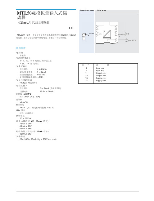
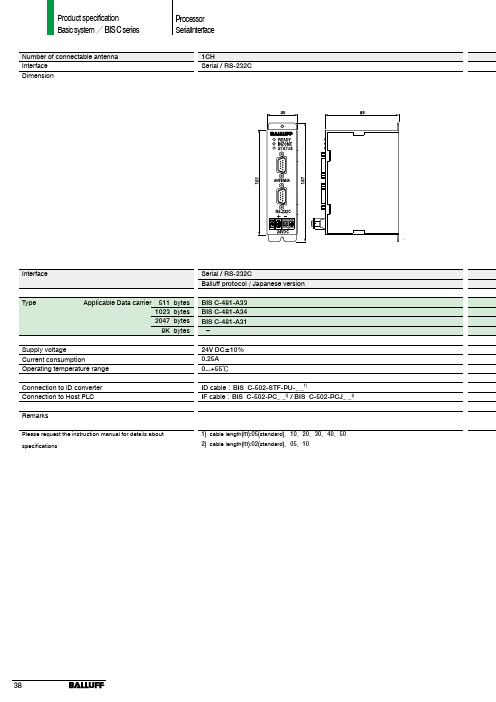
SLA5041中文资料
- 格式:pdf
- 大小:20.95 KB
- 文档页数:1
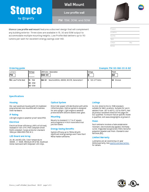
Stonco_LowProfileWall_SpecSheet 08/21 page 1 of 2Ordering guideExample: PW-50-NW-G1-8-BZLuminairePWWattageLED Color – GenerationNW-G1Voltage8FinishBZPW Low Profile Wall15 15W 30 30W 50 50WNW-G1 Neutral White, 4000K, 80 CRI, Generation 18120-277 VoltsBZ BronzeHousingDie-cast aluminum housing with UV stabilized polycarbonate lens mounted with stainless steel hardware.IP RatingLED light engine is weather proof rated IP65.ElectricalElectrical Driver efficiency (>90% at full load). Available in 120-277V. IP65 compliant driver. RoHS compliant. Surge protector standard. 10KA per ANSI/IEEE C62.41.2.LED Board and Array24, 48, and 80 LEDs. Color temperature4000K, +/- 500K. Minimum CRI of 80. Aluminum metal clad board with midpower LED chips.Optical SystemDirect mid-power LED distribution with white reflective plate. Optical system is designed for zero uplight. Light engine is weather protected with silicone sealed clear glass.MountingMounts to standard 3 ½” to 4” square and octagonal or 4 inch round electrical junction boxes.Energy Saving BenefitsSystem efficacy up to 110lms/W withsignificant energy savings over Pulse Start Metal Halide luminaires.ListingsUL/cUL listed to the UL 1598 standard,suitable for Wet Locations. Suitable for use in ambient from -30° to 40°C (-22°to 104°F). Not all product variations listed on this page are DLC qualified. To ensure that an specific model is qualified, visit /searchFinishEach luminaire receives a fade andabrasion resistant, electrostatically applied, thermally cured, triglycidal isocyanurate (TGIC) textured polyester powdercoat finish. Standard color isbronze (BZ).Limited WarrantyLuminaires are all covered by a 5-yearlimited warranty. See /warranties for details.Specifications Stonco Low profile wall mount features a discreet design that will complement any building exterior. Three sizes are available in 15, 30 and 50W output to accommodate multiple mounting heights. Low Profile Wall delivers up to 110 lumens per watt for excellent energy savings over HID.Dimensions1. Predicted performance derived from LED manufacturer's data and engineering design estimates, based on IESNA LM-80 methodology. Actual experience may vary due to field application conditions.2. L70 is the predicted time when LED performance depreciates to 70% of initial lumen output.3. Calculated per IESNA TM 21-11. Published L 70 hours limited to 6 times actual LED test hoursPredicted Lumen Depreciation Datathreaded side holes with plugs, 1 each sidethreaded side holes with plugs, 1 each sidethreaded side holes with plugs, 1 each sidePW15PW30PW501. Wattage and lumen output may vary by due to LED manufacturer forward volt specification and ambient temperature. Wattage shown is average for 120V through 277V input. Measured wattage may vary due to variation in input voltage.2. Lumen values based on photometric tests performed in compliance with IESNA LM-79. Contact *************************************************************************LED Wattage and Lumen ValuesPredicted performance derived from LED manufacturer’s data and engineering design estimates, based on IESNA LM-80 methodology. Actual experience may vary due to field application conditions.L70 is the predicted time when LED performance depreciates to 70% of initial lumen output. Calculated per IESNA TM21-11. Published L70 hours limited to 6 times actual LED test hours.PW LED Low profile wall15W, 30W, and 50WFILENAME HERE XX/2019page 2 of 2© 2021 Signify Holding. All rights reserved. The information provided herein is subject to change, without notice. Signify does not give any representation or warranty as to the accuracy or completeness of the information included herein and shall not be liable for any action in reliance thereon. The information presented in this document is not intended as any commercial offer and does not form part of any quotation or contract, unless otherwise agreed by Signify.Stonco_LowProfileWall_SpecSheet 08/21 page 2 of 2 Signify North America Corporation200 Franklin Square Drive, Somerset, NJ 08873Telephone 855-486-2216Signify Canada Ltd. 281 Hillmount Road,Markham, ON, Canada L6C 2S3 Telephone 800-668-9008All trademarks are owned by Signify Holding or their respective owners.。
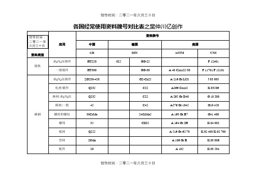

船用铝合金板材型号1. 引言船用铝合金板材是一种广泛应用于船舶制造和海洋工程领域的重要材料。
它具有优异的抗腐蚀性能、良好的强度和轻质化特点,因此受到了船舶制造商和设计师的青睐。
本文将介绍几种常见的船用铝合金板材型号,包括其特点、应用领域以及相关标准。
2. 常见型号及特点2.1 5083铝合金板材5083铝合金板材是一种常用的船用铝合金板材,其主要特点包括:•高强度:5083铝合金板材具有较高的抗拉强度和屈服强度,能够满足大多数船只在海上工作时所需承受的载荷。
•良好的耐蚀性:5083铝合金板材具有优异的耐腐蚀性能,能够有效抵御海水和大气环境中的侵蚀。
•轻质化:5083铝合金板材相对于传统钢材而言,具有较轻的重量,可以减轻船只的总重量,提高船只的速度和燃油效率。
5083铝合金板材常用于船体的结构件、甲板、储罐等部位,尤其适用于涉及到海水腐蚀环境的船只。
2.2 5454铝合金板材5454铝合金板材是另一种常见的船用铝合金板材,其主要特点包括:•中等强度:5454铝合金板材具有适中的抗拉强度和屈服强度,在一些要求较高强度但不需要极高强度的应用场景中得到广泛应用。
•抗腐蚀性能优异:5454铝合金板材能够有效抵御海水和大气环境中的侵蚀,具有良好的耐腐蚀性能。
•抗疲劳性能好:5454铝合金板材在长期使用过程中,具有较好的抗疲劳性能,能够承受循环载荷带来的应力。
5454铝合金板材广泛应用于船体结构、油箱、液罐、船舶内部装饰等领域。
2.3 6082铝合金板材6082铝合金板材是一种高强度的船用铝合金板材,其主要特点包括:•极高的强度:6082铝合金板材具有极高的抗拉强度和屈服强度,能够满足对强度要求较高的船只和海洋工程项目。
•良好的加工性能:6082铝合金板材具有良好的可焊性和可加工性,方便制造和加工过程中的操作。
•抗腐蚀性能优异:6082铝合金板材能够有效抵御海水和大气环境中的侵蚀,具有良好的耐腐蚀性能。
6082铝合金板材常用于船体结构、桅杆、梁柱等部位,适用于对强度要求较高且需要经常承受大风浪冲击的船只。
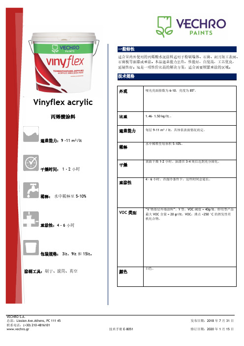
一般特性适合室内外使用的丙烯酸水泥涂料适用于粉刷墙体、石膏、刮刀加工表面、石膏板等新漆或重涂。
本品遮盖能力出色,性能好,白度高,工艺优良,延展性好。
这是一项性价比高的解决方案,适合需要频繁重涂的区域。
技术规格外观哑光亮面指数为 6-10,亮度为 85ο。
比重 1.46– 1.50 kg/lt.。
遮盖能力每层 9-11 m² / lt,具体依表面情况而定。
稀释水中稀释至每体积 5-10%。
干燥表面干燥 1-2 小时。
油漆在 3-4 周后达到充分固化。
重涂性4 - 6 小时。
在湿冷条件下,这些时间会延长。
VOC 类别“矿物基层外墙涂料”。
Y型。
VOC 阈值 = 40g/lt。
即用型产品最大 VOC 含量 = 20 gr/lt。
VOC:沸点 <250 °C 的挥发性有机化合物。
颜色白色。
Vinyflex acrylic丙烯酸涂料遮盖能力:9 -11 m²/lt干燥时间: 1 - 2 小时稀释:水中稀释至 5-10%重涂性:4 - 6 小时包装规格: 3lt、9lt 和 15lt。
涂刷工具:刷子、滚筒、真空彻底清洁表面的灰尘、油渍、旧漆、散件、霉菌残留等。
用砂纸轻轻地打磨表面。
使用石灰、胶水、旧漆或新漆的表面用 Smaltoplast Universal Primer 或 SMALTODUR 底漆进行底漆处理,而被尼古丁污渍、废气、散热器烟雾、烟雾、记号笔、真菌、霉菌、油渍污染的表面用 SMALTOX hydro或 SMALTOX mono 进行底漆处理。
涂刷方法用前充分搅拌。
涂两层 VINYFLEX ACRYLIC 。
施工过程中,始终将工具放置在容器或调漆盘中,让其保持“湿润”。
将工具上的多余油漆充分沥干到漆盒中,之后用 VECHRO 1 号稀释剂、热水和肥皂清洗。
如果油漆已干,只能用强力洗涤剂去除。
请勿将洗涤液排入下水道。
温度 8-30℃,相对湿度低于 80%。
涂刷过程中的不利条件会影响产品的最终性能。

INSTALLATION INSTRUCTIONS32M-06009-05SLATE™ Low Torque Actuator SeriesFOR COMMERCIAL AND INDUSTRIAL MODELS R8001M1050/U, R8001M1150/U, R8001M4050/U, R8001M4150/UAPPLICATIONSLATE brings configurable safety and programmable logic together into one single platform. The SLATE program can easily be customized for almost any application—offering virtually limitless development opportunities with far less complexity.The SLATE Low Torque Actuator series includescommercial- and industrial-grade 1/4-turn actuators available in 50 and 150 in/lb models with highlyrepeatable position accuracy designed specifically to integrate with the SLATE system. This series is well suited for the precise control of air and gas flow and can operate in a wide range of temperatures and environmental conditions.SLATE™ Low Torque Actuator can be easily mounted to the following valves using the mounting kits noted below. These kits can be ordered via .•Maxon CV Valve Series (1/2"–2")mounting kit #50123928-001•Honeywell V51E Valve Series (1-1/2"–2")mounting kit #50124386-001 and mounting kit #32003396-001•Honeywell V51E Valve Series (2-1/2"–4")mounting kit #50124386-001 and mounting kit #32003396-002•Honeywell V5197A Valve Series (3/4"–3")mounting kit #50124386-001FEATURES AND BENEFITS•Offered in two different configuration options:—NEMA 1 rated, operating in a temperaturerange of -18 to 158°F (-28 to 70°C) with 450 positions over a 90° span—NEMA 4 rated, operating in a temperaturerange of -40 to 158°F (-40 to 70°C) with 900 positions over a 90° span •Field-reversible clockwise and counterclockwise rotation operation.•Internal temperature, valve status, health diagnostics, and error codes reporting.•Robust, heavy-duty construction, continuous duty cycle-rated.•Closed loop position control via Modbus RS-485 communications as an input to the SLATE Fuel Air Ratio Module, part R8001C6001.•Dual 1/2-in knockout conduit connections.•1/2-in keyed output shaft with a 1/8-in square key.•Die-cast aluminum base with high-impact resistant, reinforced plastic cover.•Meets UL353 Safety for Limit Controls.•Meets UL1998 when used with R8001C6001 SLATE Fuel Air Ratio Module.APPROVALSSLATE Commercial ModelUnderwriters LaboratoriesMeets UL353 Safety for Limit Controls.Meets UL1998 when used with R8001C6001 SLATE Fuel Air Ratio Module.CE2009/142/EC: Gas Appliance Directive(EN 12067-2:2004, EN298-2012)SLATE™ LOW TORQUE ACTUATOR SERIES32M-06009—052SPECIFICATIONSSupply Voltage (Peak Current):DC model: 24VDC +10/-20%Power:50 in/lb: 10 Watts maximum 150 in/lb: 25 Watts maximum Rotation: Max span: 90° usableResolution:Commercial: 450 positions (0.2° resolution)Industrial: 900 positions (0.1° resolution)Control Deadband:Commercial: ±0.2 degrees Industrial ±0.1 degreesDimensions in in (mm): 6-11/16 x 5-29/64 x 5-29/64(170 x 138 x 138); See Fig. 1Weight: 3 Lbs. (1.4 Kg)Operating Temperature:-28 to +70°C (-18 to +158°F) for commercial mod-els; -40to +70°C (-40 to +158°F) for industrial models Storage Temperature: -40 to +80°C (-40°F to +176°F) Relative Humidity:0 to 99% non condensing (for commercial models)Vibration: Honeywell V2 test specification; 3 axes tested as follows:2-Hour Performance/Resonant Detection Sweep:Vibration sinusoidal: 5 Hz - 30 Hz;Amplitude: 0.012mil pk/pk75 mmVibration sinusoidal: 30 Hz – 300 Hz at 0.6GEndurance: 1.1G for 2 hours at resonant frequen-cies EMC: EN61000-6-1/2/3 (See Safety and Agency Approval Requirements), FCC Part 15, Level A EN55022, Level A Enclosure:NEMA1 (commercial models)NEMA 4 (industrial models)Models:Model Number DescriptionCommercialR8001M105050 in/lb Actuator NEMA 1 Enclosure R8001M1150150 in/lb Actuator NEMA 1Enclosure IndustrialR8001M405050 in/lb Actuator NEMA 4 Enclosure R8001M4150150 in/lb Actuator NEMA 4EnclosureTable 1. Model Specifications.Actuator Options/Specs Commercial ModelIndustrial Model50 in-lb R8001M1050150 in-lb R8001M115050 in-lb R8001M4050150 in-lb R8001M4150Communication RS-485 non-isolated RS-485 non-isolated RS-485 Isolated RS-485 Isolated Fault Annunciation Generic Alarm Generic Alarm Yes Yes Enhanced Data Logging None None Yes Yes Resolution .2 Degree .2 Degree .1 Degree .1 Degree Repeatability.2 Degree .2 Degree .1 Degree .1 Degree Duty Cycle (Act Availability)100%100%100%100%Opening Span 90 Degrees 90 Degrees 90 Degrees 90 Degrees 90 Degree Travel Time 30 sec 30 sec 15 sec max 15 sec max Minimum Operating Temperature-28°C (-18°F)-28°C (-18°F)-40°C (-40°F)-40°C (-40°F)Maximum Operating Temperature 70°C (158°F)70°C (158°F)70°C (158°F)70°C (158°F)Temp Sensor Yes; Alarm Only Yes; Alarm Only Yes; Alarm and Real Time Data Yes; Alarm and Real Time Data Output1/2-in Keyed Output Shaft 1/2-in Keyed Output Shaft 1/2-in Keyed Output Shaft 1/2-in Keyed Output Shaft Keyed Connection 1/8-in Square Key 1/8-in Square Key 1/8-in Square Key 1/8-in Square KeyConduit Connections1/2-in Conduit Knockouts (2) (Shipped Closed)1/2-in Conduit Knockouts (2) (Shipped Closed)1/2-in Conduit Knockouts (2) (Shipped Closed)1/2-in Conduit Knockouts (2) (Shipped Closed)SLATE™ LOW TORQUE ACTUATOR SERIES332M-06009—05Fig. 1. Dimensions in in (mm).INSTALLATION INSTRUCTIONSWARNINGRead CarefullyPlease read the operating and mounting instructions before using the equipment. Install the equipment in compliance with the prevailing regulations.Bedrijfs- en montagehandleiding voor gebruik goed lezen! Apparaat moet volgens degeldende voorschriften worden geïnstalleerd.Lire les instructions de montage et de service avant utilisation! L ’appareil doitimperativement être installé selon les règlementations en vigueur.Betriebs- und Montageanleitung vor Gebrauch lesen! Gerät muß nach den geltenden Vorschriften installiert werden.NOTICELanguage translations for this document are available at .Safety requirementsWARNINGSafety NoticeThe SLATE Actuator has been independently evaluated by Underwriters Laboratories toprovide position feedback to the SLATE Fuel Air Ratio Module. The safety of the overall system is ultimately the responsibility of: 1) Theupstream safety control that commands and monitors the SLATE Actuator, and 2) the trained commissioning engineer that configures the unit for system operation.WARNINGSafety HazardBefore operating this product, check all specifications and safety requirements toensure the product is suitable and safe for the intended application. In addition, read all installation, commissioning, and operating instructions. The SLATE Actuator must be set up and maintained in the field by qualified personnel. If the equipment is used in amanner not specified, the protection provided by the equipment may be impaired.SLATE™ LOW TORQUE ACTUATOR SERIES32M-06009—054MountingThe actuator assembly may be installed in any orientation.WARNINGKeep Free of Dust and Water•Maintain the integrity of the enclosure by using NEMA 4X rated dust- and water-tight electrical connectors.•Use cable-sealing grips and strain-relief loops for any cord or cable.•Plug unused conduit holes. Use internal sealing materials on all conduit connections. Moisture can have a harmful effect on device internals if permitted to enter through wiring connectors.•Ensure that the device connection is not at a low point of the conduit to avoidcondensation run-off into the housing; install a drip loop if necessary.•All cover screws should be tightened to the specified torque. See Fig. 4.•Cover screws should be checked periodically to ensure adequate sealing protection.If you are mounting the SLATE™ Low Torque Actuator using third party valves, it is important to follow the following assembly instructions:1.Ensure that the SLATE™ Low Torque actuatorhas sufficient torque for the valve's required break-away torque. Also consider the line pressure when making this calculation.2.Turn off the fuel supply upstream from theapplicable valve.3.Remove all external hardware from the thirdparty valve.4.The SLATE actuator's shaft is ½-in. diameterwith a 1/8-in. square key. For a smaller 3/8-in. valve shaft you must insert an adapter so that the two shafts are concentrically aligned, ensure that the set screws solidly contact both shafts.5.If the bracket assembly permits, attach thecoupling to the valve and the actuator first, ensuring exact alignment. After the coupling is tightened, assemble and tighten the mounting brackets. Do not tighten the mounting brackets first.6.Observe the actuator while it travels over itsentire range and ensure smooth operation. If sticking/binding is observed, or if Slate reports actuator error codes, the actuator shaft is not properly aligned and must be re-adjusted.Ensure the media temperature cannot exceed the valve or actuator ratings. Use a coupling with thermal breaks if required. If the possibility exists for radiant heating (such as a furnace application), install a thermal barrier.Ensure that pipe and ductwork are free of debris that could impair valve function.See Fig. 2 for the locations of the mounting holes. The mounting holes are threaded for M6 x 1 x 1/2-in (12mm) fasteners.Fig. 2. Mounting holes.Note the quadrant of the keyway and rotation direction. See Fig. 3.Fig. 3. Actuator rotation direction.NOTE:The SLATE Actuator ships CCW as default.Electrical installationWARNINGElectrical Shock Hazard.Can cause severe injury, death or equipment damage.Disconnect the power supply before beginning installation to prevent electrical shock and equipment damage. More than one power supply disconnect can be involved.Wiring terminalsFig. 4 indicates each wiring terminal and Table 2 identifies each terminal’s signal type and function.SLATE™ LOW TORQUE ACTUATOR SERIES532M-06009—05Fig. 4. Wiring terminals.To access the field wiring compartment for power and signal connections:1.Remove the 2 screws and cover from the top ofthe actuator housing.2.Pass all customer-supplied wires into the enclo-sure through the 2 conduit hubs.WARNINGEquipment DamageTo ensure physical protection as well aselectromagnetic immunity, the use of flexible, sunlight-resistant, jacketed, metallic, water-tight conduit is required. The conduit should be connected to earth ground on both ends.3.One or both conduit holes may be used when wiring an actuator.4.In addition to a grounded conduit, the use of shielded, twisted-pair cable is strongly recom-mended for DC power and signal wires. The shield drain wires should be landed to chas-sis/earth on both ends of the cable, but ONLY if a conduit is also grounded on both ends. In other cases, earth the shields at actuator end only.Input powerIMPORTANTUse DC power only.Use cable rated for the temperatures and voltages required by the application. Use a gauge of wire to minimize voltage loss (droop) over long cable runs, especially at full current load. Ensure that voltage specifications are met under all conditions. See Table 2.A fuse or breaker should be installed at the power source. If the power supply is not factory-supplied, a SELV (Safety Extra Low Voltage) rated supply with regulated output must be provided.Communication (Modbus over RS-485)Use appropriate communication cable. A network will consist of a customer’s Modbus master (withtermination) and one or more actuator slaves. See SLATE documentation for wiring specifics.NOTE:On commercial models only:Do not wire the non-isolated common terminal to the Slate system; leave itunconnected. Instead, wire the 24V- of the actuator supply to Pin 2 of the SlateSub-Base. If all actuators share the same supply, only one connection is work layouts should be arranged so thatbranch/homerun length does not exceed 300 feet for commercial actuators, or 2000 feet for industrial actuators.SLATE™ LOW TORQUE ACTUATOR SERIES32M-06009—0561 Do not wire the non-isolated common terminal to the Slate system; leave it unconnected. Instead, wire the24V- of the actuator supply to Pin 2 of the Slate Sub-Base. If all actuators share the same supply, only one con-nection is needed.Table 2. Wiring Terminal Identification.TypeTerminalDescriptionWiringPE (Protective Earth)Chassis ground screw Chassis connection for mains power and shield/drain wiresFollow local codes for safety earth installation. See Electrical installation section for shield drain installation instructions.DC power terminals 24V+24VDC positive terminal Shielded twisted pair cable isrecommended. A replaceable 2A fuse is provided on all actuators. Use a slow blow fuse if additional external fusing is desired. Required gauges are:Up to 80 ft: 24 AWG Up to 120 ft: 22 AWG Up to 500 ft: 16 AWG Up to 800 ft: 14 AWG Up to 1200 ft: 12 AWG24V-24VDC negative terminalLow voltage communication (Modbus over RS-485)Industrial models only: R8001M4050, R8001M4150RS485 In+Isolated RS-485: positive Shielded twisted pair cable with a separate common wire is recommended. See Electrical installation section for length limitations. Use 12–24 AWG wire.NOTE:Shield should be tied to chas-sis at Actuator side; do not connect at SLATE (control-ler) side.RS485 In-Isolated RS-485: negative RS485COM Isolated RS-485: commonNOTE:Must be connected forreliable performance.Low voltage communication (Modbus over RS-485)Commercial modelsonly:R8001M1050, R8001M1150RS485 In+Non-isolated RS-485: positiveRS485 In-Non-isolated RS-485: negative RS485COM Non-isolated RS-485: common See note 1SLATE™ LOW TORQUE ACTUATOR SERIES732M-06009—05OPERATING INSTRUCTIONS The SLATE Actuator is designed specifically for the SLATE Fuel Air Ratio Module. For actuator operation and programming information, see the SLATE Fuel Air Ratio Module document 32-00006 and other SLATE system documentation (Base Module document 32-00005, and System Checkout guide 32-00016).Read the instruction manual carefully before initiating the start-up and adjustment procedure. Verify that all of the equipment associated with and necessary to the safe operation of the system has been installed correctly, that all pre-commissioning checks have been carried out successfully and that all safety-related aspects of the installation are properly addressed.OverviewSLATE Actuator provides multiple methods foractuator commissioning, precise closed-loop valve or damper position control, and health monitoring.•Position can be commanded via Modbus using the SLATE Fuel Air Ratio Module.•Commissioning is accomplished through the SLATE Fuel Air Ratio Module.TROUBLESHOOTINGIf the two shafts are not perfectly and concentrically aligned, additional binding and torque will beintroduced into the assembly causing error codes to be sent from the SLATE actuator to the SLATE Fuel Air Ratio Module resulting in an inability to properly commission the system. If you are receiving actuator error codes either on the SLATE main module or in the error code register, check the mounting brackets and coupling's alignment and make necessary adjustments.Alarm and lockout event reportingSLATE alarm and lockout codes are accessed through the SLATE Fuel Air Ratio Module or using the SLATE touchscreen display. See documents 32-00013 and 32-00006 for more information.The Low-Torque Actuators also display statusmessages through LED blinks. The LED is on the PCB inside the unit. These can be used for troubleshooting purposes.The cover of the Low-Torque Actuators must be removed to see the two LEDs:•G reen LED: displays status, including alarm codes •Yellow LED: displays communication activity (on RS-485, bus is working and actuator is communicating with SLATE system)The normal and error codes are shown in Table 3.Table 3. Alarm LED Codes.LED code Error CharacteristicActionContinuous Blinking Normal State – Ready to operate None.1Out of range – Actuator is out of normal operating quadrant Command actuator to normal operational range.2Not calibrated – Actuator not (Factory) calibrated Factory calibration data lost; replace actuator.3Low Voltage Check actuator input voltage.4High TemperatureReduce ambient temperature; shield actuator from heat sources.5Mechanical binding, electrical shorts, or internal electronics fault.Check all cables and electrical connections; check for debris or water on electronics; check for mechanical binding or slipping; if persistent, replace actuator.5 or Dark Plus Continuous ResetLockoutCheck power; replace actuator.For More InformationThe Honeywell Thermal Solutions family of products includes Honeywell Combustion Safety, Eclipse, Exothermics, Hauck, Kromschröder and Maxon. To learn more about our products, visit or contact your Honeywell Sales Engineer.Honeywell Process SolutionsHoneywell Thermal Solutions (HTS) 1250 West Sam Houston Parkway South Houston, TX 77042ThermalSolutions.honeywellSLATE™ LOW TORQUE ACTUATOR SERIES® U.S. Registered Trademark© 2017 Honeywell International Inc. 32M-06009—05 M.S. Rev. 07-17 Printed in United StatesTable 4 shows information about Lockout conditions.Table 4. Lockout Conditions.Lockout Code Lockout CharacteristicComments1RAM Test of internal memory failed 2RAM DMA Test of internal memory failed 3Flash Memory Program corruption4Watchdog Startup Internal watchdog unit failure 5Safety Variables Safety data corruption 6Stack Overflow Program execution error 7System Tick Program execution error 8Main Loop Program execution error 9Processor FaultInstruction test failure 10Processor Fault – MemoryRAM/ROM failure。

LM5041Cascaded PWM ControllerGeneral DescriptionThe LM5041PWM controller contains all of the features necessary to implement either current-fed or voltage-fed push-pull or bridge power converters.These “Cascaded”topologies are well suited for multiple output and higher power applications.The LM5041’s four control outputs in-clude:the buck stage controls (HD and LD)and the push-pull control outputs (PUSH and PULL).Push-pull outputs are driven at 50%nominal duty cycle at one half of the switching frequency of the buck stage and can be configured for either a guaranteed overlap time (for current-fed applications)or a guaranteed both-off time (for voltage-fed applications).Push-pull stage MOSFETs can be driven directly from the internal gate drivers while the buck stage requires an exter-nal driver such as the LM5102.The LM5041includes a high-voltage start-up regulator that operates over a wide input range of 15V to 100V.The PWM controller is designed for high-speed capability including an oscillator frequency range up to 1MHz and total propagation delays of less than 100ns.Additional features include:line Under-Voltage Lock-out (UVLO),soft-start,an error amplifier,precision voltage reference,and thermal shutdown.Featuresn Internal Start-up Bias Regulatorn Programmable Line Under-Voltage Lockout (UVLO)with Adjustable Hysteresis n Current Mode Controln Internal Error Amplifier with Reference n Dual Mode Over-Current Protection n Leading Edge Blankingn Programmable Push-Pull Overlap or Dead Time n Internal 1.5A Push-Pull Gate Drivers n Programmable Soft-startn Programmable Oscillator with Sync Capability n Precision Reference n Thermal ShutdownApplicationsn Telecommunication Power Converters n Industrial Power Converters n Multi-Output Power Converters n+42V Automotive SystemsPackagesn TSSOP-16n LLP-16(5x5mm)Thermally EnhancedTypical Application Circuit20074901Simplified Cascaded Push-Pull Power ConverterAugust 2003LM5041Cascaded PWM Controller©2003National Semiconductor Corporation Connection Diagram2007490216-Lead TSSOP,LLPOrdering InformationOrder Number Package Type NSC Package Drawing Supplied AsLM5041MTC TSSOP-16MTC-1692Units per anti-static tube LM5041MTCX TSSOP-16MTC-162500Units on Tape and Reel LM5041SD LLP-16SDA-16A Available Soon LM5041SDXLLP-16SDA-16AAvailable SoonPin DescriptionPIN NAME DESCRIPTIONAPPLICATION INFORMATION1V IN Source Input Voltage Input to start-up regulator.Input range 15V to 100V.2FBFeedback SignalInverting input for the internal error amplifier.The non-inverting input is connected to a 0.75V reference.3COMP Output of the Internal Error Amplifier There is an internal 5k Ωresistor pull-up on this pin.The error amplifier provides an active sink.4REFPrecision 5volt reference outputMaximum output current:10mA.Locally decouple with a 0.1µF capacitor.Reference stays low until the line UV and the V CC UV are satisfied.5HD Main Buck PWM control outputBuck switch PWM control output.The maximum duty cycle clamp for this output corresponds to an off time of typically 240ns per cycle.The LM5101or LM5102Buck stage gate driver can be used to level shift and drive the Buck switch.6LD Sync Switch control outputSync Switch control output.Inversion of HD output.The LM5101or LM5102lower drive can be used to drive the synchronous rectifier switch.7V CCOutput from the internal high voltage start-up regulator.Regulated to 9volts.If an auxiliary winding raises the voltage on this pin above the regulation setpoint,the internal start-upregulator will shutdown,reducing the IC power dissipation.8PUSHOutput of the push-pull driversOutput of the push-pull gate driver.Output capability of 1.5A peak .L M 5041 2LM5041 Pin Description(Continued)PIN NAME DESCRIPTION APPLICATION INFORMATION9PULL Output of the push-pull drivers Output of the push-pull gate driver.Output capabilityof1.5A peak.10PGND Power ground Connect directly to analog ground.11AGND Analog ground Connect directly to power ground.12CS Current sense input Current sense input to the PWM comparator(CMcontrol).There is a50ns leading edge blanking onthis ing separate dedicated comparators,ifCS exceeds0.5V the outputs will go into cycle bycycle current limit.If CS exceeds0.6V the outputswill be disabled and a soft-start commenced.13SS Soft-start control An external capacitor and an internal10uA currentsource,set the soft-start ramp.The controller willenter a low power state if the SS pin is below theshutdown threshold of0.45V14TIME Push-Pull overlap and dead time control An external resistor sets the overlap time or deadtime for the push-pull outputs.A resistor connectedbetween TIME and GND produces overlap.Aresistor connected between TIME and REF producesdead time.15RT/SYNC Oscillator timing resistor pin and sync An external resistor sets the oscillator frequency.This pin will also accept an external oscillator.16UVLO Line Under-Voltage Shutdown An external divider from the power converter sourcesets the shutdown levels.Threshold of operationequals2.5V.Hysteresis is set by a switched internalcurrent source(20µA).3Block DiagramSimplified Block Diagram20074903L M 5041 4Absolute Maximum Ratings(Note1) If Military/Aerospace specified devices are required, please contact the National Semiconductor Sales Office/ Distributors for availability and specifications.V IN to GND100VV CC to GND16VAll Other Inputs to GND-0.3to7VJunction Temperature150˚CStorage Temperature Range -65˚C to+150˚CESD Rating2kVLead temperature(Note2)Wave4seconds260˚CInfrared10seconds240˚CVapor Phase75seconds219˚COperating Ratings(Note1)V IN15to90VJunction Temperature-40˚C to+105˚CElectrical CharacteristicsSpecifications with standard typeface are for T J=25˚C,and those with boldface type apply over full Operating Junction Temperature range.V IN=48V,V CC=10V,RT=26.7kΩ,R SET=20kΩ)unless otherwise stated(Note3)Symbol Parameter Conditions Min Typ Max Units Startup RegulatorV CC Reg V CC Regulation open circuit8.799.3V V CC Current Limit(Note4)1525mA I-V IN Startup RegulatorLeakage(external VccSupply)V IN=100V145500µAShutdown Current(Iin)UVLO=0V,V CC=open350450µA V CC SupplyV CC Under-voltage Lockout Voltage (positive going V cc)V CC Reg-400mVV CC Reg-275mVVV CC Under-voltageHysteresis1.72.1 2.6VSupply Current(I CC)C L=034mA Error AmplifierGBW Gain Bandwidth3MHz DC Gain80dBInput Voltage V FB=COMP0.7350.750.765VCOMP Sink Capability V FB=1.5V,COMP=1V48mA Reference SupplyV REF Ref Voltage I REF=0mA 4.855 5.15V Ref VoltageRegulationI REF=0to10mA2550mVRef Current Limit1520mA Current LimitILIM Delay to Output CS Step from0to0.6VTime to Onset of OUTTransition(90%)C L=040nsCycle by CycleThreshold Voltage0.450.50.55VCycle Skip Threshold Voltage Resets SS capacitor;auto restart0.550.60.65VLeading EdgeBlanking Time50nsCS Sink Current (clocked)CS=0.3V25mALM50415Electrical Characteristics(Continued)Specifications with standard typeface are for T J =25˚C,and those with boldface type apply over full Operating Junction Temperature range .V IN =48V,V CC =10V,RT =26.7k Ω,R SET =20k Ω)unless otherwise stated (Note 3)Symbol ParameterConditionsMin Typ Max Units Soft-StartSoft-start Current Source71013µA Soft-start to COMP Offset0.350.550.75V Shutdown Threshold0.250.50.75V OscillatorFrequency1(RT =26.7K Ω)T J =25˚C180175200220225kHz Frequency2(RT =7.87K Ω)515600685kHz Sync threshold33.5V PWM ComparatorDelay to OutputCOMP set to 2VCS stepped 0to 0.4V,Time to onset of OUT transition low25nsMax Duty Cycle TS =Oscillator Period (Ts-240ns)/Ts)%Min Duty Cycle COMP =0V%COMP to PWM Comparator Gain 0.32COMP Open Circuit VoltageFB =0V4.1 4.85.5V COMP Short Circuit CurrentFB =0V,COMP =0V0.611.4mASlope CompensationSlope Comp AmplitudeDelta increase at PWM Comparator to CS110mVUVLO ShutdownUnder-voltage Shutdown 2.44 2.5 2.56V Under-voltage ShutdownHysteresis Current Source162024µABuck Stage OutputsOutput High level 5(V REF )V Output High Saturation I OUT =10mA REF =V OUT 0.51V Output Low Saturation I OUT =−10mA 0.51V Rise Time C L =100pF 10ns Fall TimeC L =100pF10ns Push-Pull OutputsOverlap TimeR SET =20k ΩConnected to GND,50%to 50%Transitions6090120nsDead Time R SET =20k ΩConnected to GND,50%to 50%Transitions6595125nsL M 5041 6LM5041 Electrical Characteristics(Continued)Specifications with standard typeface are for T J=25˚C,and those with boldface type apply over full Operating Junction Temperature range.V IN=48V,V CC=10V,RT=26.7kΩ,R SET=20kΩ)unless otherwise stated(Note3)Symbol Parameter Conditions Min Typ Max Units Output High Saturation I OUT=50mA0.250.5VV CC-V OUTOutput Low Saturation I OUT=100mA0.51VRise Time C L=1nF20nsFall Time C L=1nF20nsThermal ShutdownT SD Thermal Shutdown165˚C Temp.25˚C Thermal ShutdownHysteresisThermal ResistanceθJA Junction to Ambient MTC Package125˚C/WSDA Package32˚C/WNote1:Absolute Maximum Ratings are limits beyond which damage to the device may occur.Operating Ratings are conditions under which operation of the deviceis intended to be functional.For guaranteed specifications and test conditions,see the Electrical Characteristics.Note2:For detailed information on soldering plastic TSSOP and LLP packages,refer to the Packaging Data Book available from National Semiconductor Corporation.Note3:All limits are guaranteed.All electrical characteristics having room temperature limits are tested during production with T A=T J=25˚C.All hot and cold limitsare guaranteed by correlating the electrical characteristics to process and temperature variations and applying statistical process control.Note4:Device thermal limitations may limit usable range.7Typical Performance CharacteristicsV CC and V IN vs V INV CC vs I CC2007490820074909SS Pin Current vs Temp Frequency vs RT2007491520074910Overlap Time vs R SET Dead Time vs R SET2007491120074912L M 5041 8Typical Performance Characteristics(Continued)Overlap Time vs TempDead Time vs Temp2007491320074914Error Amplifier Gain Phase20074916LM50419Detailed Operating DescriptionThe LM5041PWM controller contains all of the features necessary to implement either current-fed or voltage-fed push-pull or bridge power converters.These “Cascaded”topologies are well suited for multiple output and higher power applications.The LM5041’s four control outputs in-clude:the buck stage controls (HD and LD)and the push-pull control outputs (PUSH and PULL).Push-pull outputs are driven at 50%nominal duty cycle at one half of the switching frequency of the buck stage and can be configured for either a guaranteed overlap time (for current-fed applications)or a guaranteed both-off time (for voltage-fed applications).Push-pull stage MOSFETs can be driven directly from the internal gate drivers while the buck stage requires an exter-nal driver such as the LM5102.The LM5041includes a high-voltage start-up regulator that operates over a wide input range of 15V to 100V.The PWM controller is designed for high-speed capability including an oscillator frequency range up to 1MHz and total propagation delays of less than 100ns.Additional features include:line Under-Voltage Lock-out (UVLO),soft-start,an error amplifier,precision voltage reference,and thermal shutdown.High Voltage Start-Up RegulatorThe LM5041contains an internal high-voltage start-up regu-lator,thus the input pin (Vin)can be connected directly to the line voltage.The regulator output is internally current limited to 15mA.When power is applied,the regulator is enabled and sources current into an external capacitor connected to the Vcc pin.The recommended capacitance range for the Vcc regulator is 0.1uF to 100uF.When the voltage on the Vcc pin reaches the regulation point of 9V and the internal voltage reference (REF)reaches its regulation point of 5V,the controller outputs are enabled.The Buck stage outputs will remain enabled until Vcc falls below 7V or the line Under-Voltage Lockout detector indicates that Vin is out of range.The push-pull outputs continue switching until the REF pin voltage falls below approximately 3V.In typical applications,an auxiliary transformer winding is connected through a diode to the Vcc pin.This winding must raise the Vcc voltage above 9.3V to shut off the internal start-up regulator.Powering V CC from an auxiliary winding improves efficiency while reducing the controller’s power dissipation.The recommended capacitance range for the Vref regulator output is 0.1uF to 10uF.The external V CC capacitor must be sized such that the capacitor maintains a V CC voltage greater than 7V during the initial start-up.During a fault mode when the converter aux-iliary winding is inactive,external current draw on the V CC line should be limited so the power dissipated in the start-up regulator does not exceed the maximum power dissipation of the controller.An external start-up or other bias rail can be used instead of the internal start-up regulator by connecting the V CC and the V IN pins together and feeding the external bias voltage into the two pins.Line Under-Voltage DetectorThe LM5041contains a line Under-Voltage Lockout (UVLO)circuit.An external set-point resistor divider from V IN toground sets the operational range of the converter.The divider must be designed such that the voltage at the UVLO pin will be greater than 2.5V when V IN is in the desired operating range.If the Under-Voltage threshold is not met,all functions of the controller are disabled and the controller will enter a low-power state with input current <300µA.ULVO hysteresis is accomplished with an internal 20µA cur-rent source that is switched on or off into the impedance of the set-point divider.When the UVLO threshold is exceeded,the current source is activated to instantly raise the voltage at the UVLO pin.When the UVLO pin falls below the 2.5V threshold,the current source is turned off causing the volt-age at the UVLO pin to fall.The UVLO pin can also be used to implement a remote enable /disable function.By shorting the UVLO pin to ground,the converter can be disabled.The controller can also be disabled through the soft-start pin (SS).The controller will enter a low-power off state if the SS pin is forced below the 0.45V shutdown threshold.Buck Stage Control OutputsThe LM5041Buck switch maximum duty cycle clamp en-sures that there will be sufficient off time each cycle to recharge the bootstrap capacitor used in the high side gate driver.The Buck switch is guaranteed to be off,and the sync switch on,for at least 250ns per switching cycle.The Buck stage control outputs (LD and HD)are CMOS buffers with logic levels of 0to 5V.During any fault state or Under-Voltage off state,the buck stage control outputs will default to HD low and LD high.Push-Pull OutputsThe push pull outputs operate continuously at a nominal 50%duty cycle.A distinguishing feature of the LM5041is the ability to accurately configure either dead time (both-off)or overlap time (both-on)on the complementary push-pull out-puts.The overlap/dead time magnitude is controlled by a resistor connected to the TIME pin on the controller.The TIME pin holds one end of the resistor at 2.5V and the other end of the resistor should be connected to either REF for dead time control setting or to GND for overlap control.The polarity of the current in the TIME is detected by the LM5041The magnitude of the overlap/dead time can be calculated as follows:Overlap Time (ns)=(3.66x R SET )+7Overlap Time in ns,R SET connected to GND,R SET in k ΩDead Time (ns)=(3.69x R SET )+21Dead Time in ns,R SET connected to REF,R SET in k ΩRecommended R SET programming range:10k Ωto 100k ΩCurrent-fed designs require a period of overlap to insure there is a continuous path for the buck inductor current.Voltage-fed designs require a period of dead time to insure there is no time when the push-pull transformer acts as a shorted turn to the low impedance sourcing node.The push-pull outputs alternate continuously under all conditions pro-vided REF the voltage is greater than 3V.L M 5041 10Push-Pull Outputs(Continued)20074904PWM ComparatorThe PWM comparator compares the slope compensated current ramp signal to the loop error voltage from the internal error amplifier(COMP pin).This comparator is optimized for speed in order to achieve minimum controllable duty cycles. The comparator polarity is such that0V on the COMP pin will produce zero duty cycle in the buck stage.Error AmplifierAn internal high gain wide-bandwidth error amplifier is pro-vided within the LM5041.The amplifier’s non-inverting input is tied to a0.75V reference.The inverting input is connected to the FB pin.In non-isolated applications the power con-verter output is connected to the FB pin via the voltage setting resistors.Loop compensation components are con-nected between the COMP and FB pins.For most isolated applications the error amplifier function is implemented on the secondary side of the converter and the internal error amp is not used.The internal error amplifier is configured as an open drain output and can be disabled by connecting the FB pin to ground.An internal5kΩpull-up resistor between the5V reference and COMP can be used as the pull-up for an opto-coupler in isolated applications.Current Limit/Current SenseThe LM5041contains two levels of over-current protection.If the voltage at the CS pin exceeds0.5V the present buck stage duty cycle is terminated(cycle by cycle current limit).If the voltage at the CS pin overshoots the0.5V threshold and exceeds0.6V,then the controller will terminate the present cycle and fully discharge the soft-start capacitor.A small RC filter located near the controller is recommended to filter current sense signals at the CS pin.An internal MOSFET discharges the external CS pin for an additional50ns at the beginning of each cycle to reduce the leading edge spike that occurs when the buck stage MOSFET is turned on. The LM5041current sense and PWM comparators are very fast,and may respond to short duration noise yout considerations are critical for the current sense filter and sense resistor.The capacitor associated with the CS filtermust be placed close to the device and connected directly tothe pins of the controller(CS and GND).If a current sensetransformer is used,both leads of the transformer secondaryshould be routed to the sense resistor,which should also belocated close to the IC.A resistor may be used for currentsensing instead of a transformer,located in the push-pulltransistor sources,but a low inductance type of resistor isrequired.When designing with a sense resistor,all of thenoise sensitive low power grounds should be connectedtogether around the IC and a single connection should bemade to the high current power ground(sense resistorground point).The second level current sense threshold is intended toprotect the power converter by initiating a low duty cyclehick-up mode when abnormally high currents are sensed.Ifthe second level threshold is reached,the soft-start capaci-tor will be discharged and a start-up sequence will com-mence when the soft-start capacitor is determined to be fullydischarged.The second level threshold will only be reachedwhen a high dV/dt is present at the current sense pin.Thecurrent sense transient must be fast enough to reach thesecond level threshold before the first threshold detectorturns off the buck stage driver.Very high current sense dV/dtcan occur with a saturated power inductor or shorted load.Excessive filtering on the CS pin such as an extremely lowvalue current sense resistor or an inductor that does notsaturate with excessive loading,may prevent the secondlevel threshold from being reached.If the second levelthreshold is never exceeded during an overload condition,the first level current sense will continue cycle by cyclelimiting and the output characteristic of the converter will bethat of a current source.However,a sustained overloadcurrent level can cause excessive temperatures in the powertrain especially the output rectifiers.Oscillator and Sync CapabilityThe LM5041oscillator is set by a single external resistorconnected between the RT pin and GND.To set a desiredoscillator frequency(F),the necessary RT resistor can becalculated from:LM504111Oscillator and Sync Capability(Continued)The buck stage will switch at the oscillator frequency and each push-pull output will switch at half the oscillator fre-quency in a push-pull configuration.The LM5041can also be synchronized to an external clock.The external clock must have a higher frequency than the free running fre-quency set by the RT resistor.The clock signal should be capacitively coupled into the RT pin with a 100pF capacitor.A peak voltage level greater than 3V is required for detection of the sync pulse.The sync pulse width should be set in the 15to 150ns range by the external components.The RT resistor is always required,whether the oscillator is free running or externally synchronized.The voltage at the RT pin is internally regulated to 2V.The RT resistor should be located very close to the device and connected directly to the pins of the IC (RT and GND).Slope CompensationThe PWM comparator compares the current sense signal to the voltage at the COMP pin.The output stage of the internal error amplifier generally drives the COMP pin.At duty cycles greater than 50percent,current mode control circuits are subject to sub-harmonic oscillation.By adding an additional fixed ramp signal (slope compensation)to the current sense ramp,oscillations can be avoided.The LM5041integrates this slope compensation by buffering the internal oscillatorramp and summing a current ramp generated by the oscil-lator internally with the current sense signal.Additional slope compensation may be provided by increasing the source impedance of the current sense signal.Soft-start and ShutdownThe soft-start feature allows the power converter to gradually reach the initial steady state operating point,thereby reduc-ing start-up stresses and surges.At power on,a 10uA cur-rent is sourced out of the soft-start pin (SS)to charge an external capacitor.The capacitor voltage will ramp up slowly and will limit the maximum duty cycle of the buck stage.In the event of a fault as indicated by V CC Under-voltage,line Under-voltage or second level current limit,the output driv-ers are disabled and the soft-start capacitor is discharged to ground.When the fault condition is no longer present,a soft-start sequence will begin again and buck stage duty cycle will gradually increase as the soft-start capacitor is charged.The SS pin also serves as an enable input.The controller will enter a low power state if the SS pin is forced below the 0.45V threshold.Thermal ProtectionInternal Thermal Shutdown circuitry is provided to protect the integrated circuit in the event that the maximum junction temperature is exceeded.When activated,typically at 165degrees Celsius,the controller is forced into a low-power standby state,disabling the output drivers and the bias regulator.This feature is provided to prevent catastrophic failures from accidental device overheating.L M 5041 12LM5041 Thermal Protection(Continued)20074906FIGURE1.Simplified Cascaded Half-Bridge13A p p l i c a t i o n C i r c u i t :I n p u t 35-80V ,O u t p u t 2.5V ,50A20074907L M 504114元器件交易网Physical Dimensionsinches (millimeters)unless otherwise notedMolded TSSOP-16NS Package Number MTC16Molded TSSOP-16NS Package Number SDA16ALM504115NotesLIFE SUPPORT POLICYNATIONAL’S PRODUCTS ARE NOT AUTHORIZED FOR USE AS CRITICAL COMPONENTS IN LIFE SUPPORT DEVICES OR SYSTEMS WITHOUT THE EXPRESS WRITTEN APPROVAL OF THE PRESIDENT AND GENERAL COUNSEL OF NATIONAL SEMICONDUCTOR CORPORATION.As used herein:1.Life support devices or systems are devices or systems which,(a)are intended for surgical implant into the body,or (b)support or sustain life,and whose failure to perform when properly used in accordance with instructions for use provided in the labeling,can be reasonably expected to result in a significant injury to the user.2.A critical component is any component of a life support device or system whose failure to perform can be reasonably expected to cause the failure of the life support device or system,or to affect its safety or effectiveness.National Semiconductor Americas Customer Support CenterEmail:new.feedback@ Tel:1-800-272-9959National SemiconductorEurope Customer Support CenterFax:+49(0)180-5308586Email:europe.support@Deutsch Tel:+49(0)6995086208English Tel:+44(0)8702402171Français Tel:+33(0)141918790National Semiconductor Asia Pacific Customer Support CenterEmail:ap.support@National SemiconductorJapan Customer Support Center Fax:81-3-5639-7507Email:jpn.feedback@ Tel:81-3-5639-7560L M 5041C a s c a d e d P W M C o n t r o l l e rNational does not assume any responsibility for use of any circuitry described,no circuit patent licenses are implied and National reserves the right at any time without notice to change said circuitry and specifications.。
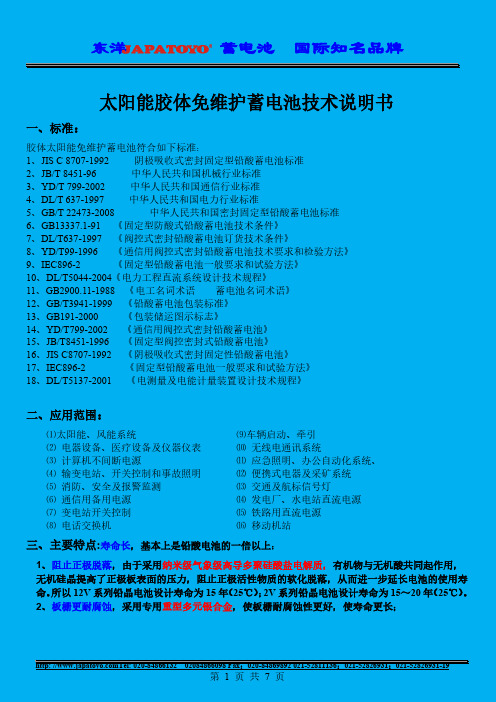
太阳能胶体免维护蓄电池技术说明书一、标准:胶体太阳能免维护蓄电池符合如下标准:1、JIS C 8707-1992 阴极吸收式密封固定型铅酸蓄电池标准2、JB/T 8451-96 中华人民共和国机械行业标准3、YD/T 799-2002 中华人民共和国通信行业标准4、DL/T 637-1997 中华人民共和国电力行业标准5、GB/T 22473-2008 中华人民共和国密封固定型铅酸蓄电池标准6、GB13337.1-91 《固定型防酸式铅酸蓄电池技术条件》7、DL/T637-1997 《阀控式密封铅酸蓄电池订货技术条件》8、YD/T99-1996 《通信用阀控式密封铅酸蓄电池技术要求和检验方法》9、IEC896-2 《固定型铅酸蓄电池一般要求和试验方法》10、DL/T5044-2004《电力工程直流系统设计技术规程》11、GB2900.11-1988《电工名词术语蓄电池名词术语》12、GB/T3941-1999 《铅酸蓄电池包装标准》13、GB191-2000 《包装储运图示标志》14、YD/T799-2002《通信用阀控式密封铅酸蓄电池》15、JB/T8451-1996 《固定型阀控密封式铅酸蓄电池》16、JIS C8707-1992 《阴极吸收式密封固定性铅酸蓄电池》17、IEC896-2《固定型铅酸蓄电池一般要求和试验方法》18、DL/T5137-2001 《电测量及电能计量装置设计技术规程》二、应用范围:⑴太阳能、风能系统⑼车辆启动、牵引⑵电器设备、医疗设备及仪器仪表⑽无线电通讯系统⑶计算机不间断电源⑾应急照明、办公自动化系统、⑷输变电站、开关控制和事故照明⑿便携式电器及采矿系统⑸消防、安全及报警监测⒀交通及航标信号灯⑹通信用备用电源⒁发电厂、水电站直流电源⑺变电站开关控制⒂铁路用直流电源⑻电话交换机⒃移动机站三、主要特点:寿命长,基本上是铅酸电池的一倍以上:1、阻止正极脱落,由于采用纳米级气象级高导多聚硅酸盐电解质,有机物与无机酸共同起作用,无机硅晶提高了正极板表面的压力,阻止正极活性物质的软化脱落,从而进一步延长电池的使用寿命。
冷作粉末高速钢型号
冷作粉末高速钢是一种高性能合金钢材,适用于高速切削和高温加工。
其优良的耐磨性、耐热性以及耐腐蚀性等特点,使其在航空、汽车、电子、机械等领域得到广泛应用。
下面列举几种常见的冷作粉末高速钢型号:
1. ASP23:具有优秀的硬度、韧性和耐磨性,在高速切削和高温加工中表现出色,常用于模具、航空器和汽车零部件的制造。
2. ASP60:硬度高、热稳定性好,适用于高速切削和高温加工,常用于切削工具、热冲模和热挤压模等领域。
3. ASP30:耐磨性优良,具有较高的硬度和强度,适用于高速切削和高温加工,常用于模具、切削工具和汽车零部件的制造。
4. ASP2052:硬度高、耐热性好,适用于高速切削和高温加工,常用于制造飞机发动机部件、导弹零部件等。
5. ASP2023:硬度高、耐腐蚀性好,适用于高速切削和高温加工,常用于制造化工设备、医疗器械等。
以上是冷作粉末高速钢的常见型号,它们各有特点,可以根据实际应用场景选择。
- 1 -。
常用灰铸铁的牌号及用途
《常用灰铸铁的牌号及用途》
嘿呀,咱今天就来讲讲常用灰铸铁的牌号和用途。
你知道不,这灰铸铁啊,就像我们生活中的老伙计,到处都有它的身影呢!
就说 HT100 这个牌号吧,它就像是个任劳任怨的小兵,一般用在不太受力的地方,比如一些简单的盖子、外壳啥的。
就好像我家那个旧花盆的托盘,我一直以为就是个普通玩意儿,后来才发现那就是用 HT100 做的呢。
再说说 HT150 呀,这可就厉害点了,能当一些不太重的机器零件呢。
我记得有次我去工厂参观,看到那些机器里面有些小部件就是用它做的。
当时我还好奇地摸了摸,心里想着,嘿,原来这就是 HT150 啊。
HT200 就更牛啦,像一些机床的床身啊、汽缸体啥的都能用上它。
我之前去一个修理店,看到师傅在修一台机床,那机床的床身看起来特别结实,师傅就说那就是 HT200 做的呢,可经得起折腾了。
HT250 呢,那可是个大力士,像大型发动机的汽缸体都得靠它。
我有次在电视上看一个关于汽车制造的纪录片,就看到那些大型设备里有好多都是用 HT250 做的部件,真的是超级厉害。
总之啊,这些常用灰铸铁的牌号都有它们各自的用处,就像我们生活中的各种工具一样,各显神通。
它们虽然不起眼,但却在各个领域默默发挥着重要的作用呢!就像我家那个花盆托盘,虽然普通,却也有着它的价值呀!哈哈!
好了,说了这么多,希望大家对常用灰铸铁的牌号及用途有了更清楚的了解啦!。
欧标RAL色号对照表(编码,英文名,中文名)欧标RAL色号对照表数字"1"开头的 1000 Green beige 米绿色 1001 Beige 米色,淡黄或灰黄 1002 Sand yellow 沙黄色 1003 Signal yellow 信号黄 1004 Goldenyellow 金黄色1005 Honey yellow 蜜黄色1006 Maize yellow 玉米黄 1007 Daffodil yellow 灰黄色 1011 Brown beige 米褐色 1012 Lemon yellow 柠檬黄 1013 Oyster white 近于白色的浅灰1014 Ivory 象牙色 1015 Light ivory 亮象牙色 1016 Sulfur yellow 硫磺色1017 Saffron yellow 深黄色1018 Zinc yellow 绿黄色1019 Grey beige 米灰色 1020 Olive yellow 橄榄黄 1021 Rape yellow 油菜黄1023 Traffic yellow 交通黄1024 Ochre yellow 赭黄色1026 Luminous yellow 亮黄色 1027 Curry 咖喱色 1028 Melon yellow 浅橙黄1032 Broom yellow 金雀花黄1033 Dahlia yellow 大丽花黄1034 Pastel yellow 粉黄色 1035 Pearl beige 米珍珠色 1036 Pearl gold 金黄珍珠1037 Sun yellow 日光黄数字“2”开头的2000 Yellow orange 黄橙色 2001 Red orange 橘红 2002 Vermilion 朱红2003 Paster orange 淡橙 2004 Pure orange 纯橙 2005 Luminous orange 亮橙 2007 Luminous bright orange 亮浅橙 2008 Bright red orange 浅红橙 2009 Traffic orange 交通橙 2011 Deep orange 深橙色2012 Salmon orange 鲑鱼橙 2013 Pearl orange 珍珠橙数字“3”开头的 3000 Flame red 火焰红3001 Signal red 信号红3002 Carmine red 胭脂红3003 Ruby red 宝石红3004 Purple red 紫红色3012 Beige red 米红色3013 Tomato red 番茄红3014 Antique pink 古粉红色3015 Light pink 淡粉红色3016Coral red 珊瑚红色3017 Rose 玫瑰色3018 Strawberry red 草莓红 3020 Traffic red 交通红3022 Salmon pink 鲑鱼粉红色 3024 Luminous red 亮红色3026 Luminous bright red 淡亮红色 3027 Raspbery red 悬钩子红色 3031 Orient red 戈亚红色 3005 Wine red 葡萄酒红3007 Black red 黑红色3009 Oxide red 氧化红3011 Brown red 红玄武土色3032 Pearl ruby red 红宝石珍珠红 3033 Pearl pink 珍珠红色数字“4”开头的4001 Red lilac 丁香红4002 Red violet 紫红色4003 Heather violet 石南紫4004 Claret violet 酒红紫4005 Blue lilac 丁香蓝4006 Traffic purple 交通紫 4007 Purple violet 紫红蓝色 4008 Signal violet 信号紫罗兰4009 Pastel violet 崧蓝紫色4010 Telemagenta 电视品红色4011 Pearl violet 珍珠紫4012 Peal blackberry 珍珠黑数字“5”开头的 5000 Violet blue 紫蓝色 5001 Green blue 蓝绿色 5002 Ultramarine blue 群青蓝 5003 Sapphire blue 蓝宝石蓝5004 Black blue 蓝黑色 5005 Signal blue 信号蓝 5007 Brillant blue 亮蓝色5008 Grey blue 灰蓝色5009 Azure blue 天青蓝5010 Gentian blue 龙胆蓝色 5011 Steel blue 钢蓝色 5012 Light blue 淡蓝色 5013 Cobalt blue 钴蓝色 5014 Pigeon blue 鸽蓝色 5015 Sky blue 天蓝色 5017 Traffic blue 交通蓝 5018 Turquoise blue 绿松石蓝5019 Capri blue 卡布里蓝色5020 Ocean blue 海蓝色5021 Water blue 不来梅蓝色 5022 Night blue 夜蓝色 5023 Distant blue 冷蓝色 5024 Pastel blue 崧蓝蓝色 5025 Pearl gentian blue 珍珠龙胆蓝5026 Pearl night blue 珍珠夜蓝数字“6”开头的6002 Leafgreen 叶绿色6003 Olive green 橄榄绿6004 Blue green 蓝绿色6005 Moss green 苔藓绿6006 Grey olrve 橄榄灰绿6000 Patina green 铜锈绿色 6001 Emerald greet 翡翠绿色6032 Signal greet 信号绿 6033 Mint turquoise 薄荷绿蓝色 6034 Pastel turquoies 崧蓝绿松石色 6035 Pearl green 珍珠绿 6036 Pearl opal green 不透明蓝白绿 6007 Bottle green 瓶绿 6008 Brown green 褐绿 6009 Fir greet 冷杉绿 6010 Grass greet 草绿色 6011 Reseda green 淡橄榄绿6012 Black green 墨绿色 6013 Reed green 芦苇绿6014 Yellow olive 橄榄黄6015 Black olive 黑齐墩果色6016 Turquoise green 绿松石绿色 6017 May green 五月红6018 Yellow green 黄绿色 6019 Pastel green 崧蓝绿色 6020 Chrome green 铭绿色6021 Pale green 浅绿色6022 Olive drab 橄榄土褐色6024 Traffic green 交通绿 6025 Fern green 蕨绿色6026 Opal green 蛋白石绿色6027 Light green 浅绿色6028 Pine green 松绿色6029 Mint green 薄荷绿数字“7”开头的7000 Squirrel grey 松鼠灰 7001 Silver grey 银灰色 7002 Olive grey 橄榄灰绿色 7003 Moss grey 苔藓绿7004 Signal grey 信号灰 7005 Mouse grey 鼠灰色7006 Beige grey 米灰色7008 Khaki grey 土黄灰色 7009 Green grey 绿灰色7010 Tarpaulin gey 油布灰 7011 Iron grey 铁灰色7012 Basalt grey 玄武石灰 7013 Brown grey 褐灰色7015 Slate grey 浅橄榄灰7016 Anthracite grey 煤灰7021 Black grey 黑灰7022 Umbra grey 暗灰7023 Concrete grey 混凝土灰 7032 Pebble grey 卵石灰 7033 Cement grey 水泥灰 7034 Yellow grey 黄灰色 7035 Light grey 浅灰色7036 Platinum grey 铂灰色7037 Dusty grey 土灰色7038 Agate grey 玛瑙灰7039 Quartz grey 石英灰7040 Window grey 窗灰色7042 Traffic grey A 交通灰A 7043 Traffic grey B 交通灰B 7044 Silk grey 深铭灰色7045 Telegrey 1 电视灰17046 Telegrey 2 电视灰27047 Telegrey 4 电视灰47048 Pearl mouse grey 珍珠鼠灰 7024 Graphite grey 石墨灰7026 Granite grey 花岗灰7030 Stone grey 石灰色7031 Blue grey 蓝灰色数字“8”开头的8000 Green brown 绿褐色8001 Ochre brown 赭石棕色8002 Signal brown 信号褐8003 Clay brown 土棕褐色8004 Coper brown 铜棕色8007 Fawn brown 鹿褐色8008 Olive brown 橄榄棕色8011 Nut brown 深棕色8012 Red brown 红褐色8014 Sepia brown 乌贼棕色8015 Chestnut brown 粟棕色 8016 Mahogany brown 桃花心木褐8017 Chocolate brown 巧克力棕色 8019 Grey brown 灰褐色8022 Black brown 黑褐色8023 Orange brown 桔黄褐8024 Beige brown 哔叽棕色8025 Pale brown 浅褐色8028 Terra brown 浅灰褐色8029 Pearl copper 珍珠铜棕色数字“9”开头的9001 Cream 彩黄色9002 Grey white 灰白色9003 Signal white 信号白9004 Signal black 信号黑9005 Jet black 墨黑色 9006 White aluminium 白铝灰色 9007 Grey aluminium 灰铝色 9010 Pure white 纯白色9011 Graphiack 石墨黑9016 Traffic white 交通白9017 Traffic black 交通黑9018 Papyrus white 草纸白 9022 Pearl light grey 珍珠浅灰 9023 Pearl dark grey 珍珠深灰。

EN 50419是欧洲标准化协会(ComitéEuropéen de Normalisation, CEN)于2006年发布的一项关于建筑材料中振动测试的标准。
该标准旨在为建筑材料制造商提供一种测试方法,以评估建筑材料在振动环境中的性能。
EN 50419标准可以应用于各种建筑材料,例如墙板、地板、屋顶瓦片、窗户等。
该标准规定了常规振动测试、冲击振动测试和频谱分析等测试方法,以确保建筑材料在振动环境中的性能和安全性。
常规振动测试是通过施加不同频率和振幅的振动,来模拟建筑结构在不同条件下的振动情况。
冲击振动测试是通过施加冲击或重击来模拟建筑物发生事故或自然灾害时的振动情况。
频谱分析是通过分析振动信号的频谱,来确定材料在不同频率下的响应和振幅变化。
通过这些测试方法,建筑材料制造商可以评估其产品在振动环境中的性能,并确保其符合CE认证的标准要求。
EN 50419标准的实施有助于提高建筑物的安全性和稳定性,保障公众的健康和安全。


不锈钢角钢切削刀具用钢介绍
切削刀具中有旋转刀具,或钻削刀具和车削刀具。
在各种制造工艺中,装载在工作机械、铣床和车床等上进行切削加工。
刀具材料要求硬度和韧性,刀具形状要求刃尖强度、切削性和切屑排出性。
这里指的切削性是指切削阻抗低。
切屑排出性是指切屑生成后尽快离开切削点,通过刃槽排出的性质。
切削刀具中旋转刀具从结构上分为两类,整体式和更换刃尖式刀具。
整体式是由切削刃的刃部和装卸筒夹持部分的杆部构成,各部位是同一种材料。
原料有超硬合金、高速工具钢、CBN等。
更换刃尖式是由刃尖、装卸夹持的杆和装卸机械主轴的刀杆构成,刃尖磨损后可以更换。
这种刃尖的材料有超硬合金、金属陶瓷和CBN等。
切削刀具的材料广泛使用的是越硬合金组成WC-Co,也有添加控制晶粒状态的各种合金成分。
表1是切削刀具用超硬合金的分类。
最近,为了提高刀具的使用寿命,在超硬合金材料表面进行涂层处理。
旋转刀具用涂层要求具有硬度、抗热性和润滑性。
抗热性用开始氧化温度表示,切削钢的涂层组成一般是Ti化合物。
刀具的使用寿命与涂层技术的进步密切相关,物理真空镀膜法之一的离子镀法的改进大大延长了刀具的使用寿命。
提高了硬度和抗氧化性的纳米复合覆膜,可以稳定切削高硬度的淬火钢。
作为设计刀具的新技术,为了降低刀具成本,缩小刃尖式刀具直径比较有效。
另外,不等分割刃和不等相位刃等刃形减振技术也在发展中。
这些技术具有抑制切削中的异常振动,延长刀具的使用寿命,提高加工效率的效果。