MicroRotoforTMCell培训教程
- 格式:doc
- 大小:2.39 MB
- 文档页数:14

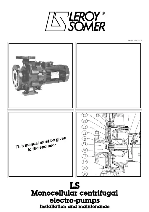
LS Monocellular centrifugal1 - GENERALThe LS range of monobloc electro-pump unitsshould be installed in accordance with theinstructions in this manual. They must not be usedin duty conditions other than those indicated in thisdocument.Should these instructions not be adhered to, or theequipment be modified in any way without LEROY-SOMER's approval, the guarantee is immediatelyrendered null and void.LEROY-SOMER cannot be held responsible if theinstructions contained in this document have notbeen followed.This manual does not take account of existing safetyrecommendations and regulations which may be inforce where the equipment is installed. It is theresponsibility of the user to ensure that these areapplied and adhered to.2 - USEThe L S range of centrifugal, mono-cellular, monoblocelectro-pump units is designed to carry water, and anyother clear liquid which is non-contaminated, non-abrasive, non-corrosive, non-explosive and compatiblewith the material of which the pump is made.For any other pumped liquid : please consult L EROY-SOMER.• Maximum content of solid particles in suspension:50 g/m 3• Maximum temperature of pumped liquid: 110 °C• Minimum temperature of pumped liquid: - 10 °C• Maximum ambient temperature: 40 °C• Maximum duty pressure of the pump(on lift) : 16 bar• Maximum pressure at intake : 10 bar• Density of pumped liquid: 1• Viscosity of pumped liquid: 1 mm 2/s 3 - CHARACTERISTICSThe dimensions of the pump body, intake and outletopenings and foot mountings conform to DIN 24255 andNFE 44111 standards.Each electro-pump unit has two identification plates; onewhich defines the hydraulics, and the other the motor.3.1 - Hydraulic characteristicsThe hydraulic characteristics are guaranteed to conformto international standard ISO 2548 class C for mass-produced pumps.3.2 - Electrical characteristics4 - HANDLINGElectro-pump units should be handled and unpacked with care.We recommend the unit is handled as shown in the sketch below.5 - STORAGEIn good storage conditions, our electro-pump units arenot at risk of deterioration.They should be stored in dry, enclosed areas, away frominclement weather conditions, dust, vibration, and shocks.If there is a risk of freezing temperatures in the storagearea, ensure that the pump has been drained.Do not place units leaning against the motor fan cover.Before commissioning or re-commissioning an electro-pump unit, always read the instructions contained in thismanual, and follow them carefully.3/h Rated current Power factor Rated power Speed of rotationFrequencySupply voltage Connection Type of motor Electro-pump serial number Mot 3 ~ DL 2,2 / 2N ° 343566DG001 kg IP 55cl F °C 40S S 1V Hz min -1kW cos ϕ A Δ 220502845 2.20.878.50Y 38028450.87 4.90Δ 230502860 2.20.828.70Y 40028600.82 5.00Δ 240502870 2.20.779.00Y 41528700.77 5.206 - INSTALLATIONElectro-pump units must be installed by personnelsuitably qualified to undertake this type of work.Install the unit as close as possible to the water supply inan easily accessible location.The suction and delivery pipes must be fitted in such away that they do not create any mechanical force on thebody of the pump.We recommend fixing the unit on a concrete pillar. Ifnecessary, wedge it in position.In some cases, the motor flange comes into contact withthe mating surface before the foot mountings. It mustthen be wedged beneath both the pump and the motor.The unit can be installed in a number of positions, butnot with the motor under the pump (see sketch below).The unit should be installed in a well-ventilated location,sheltered from inclement weather conditions.6.1 - Suction pipe This pipe must be large enough in diameter to avoid significant loss of pressure. It must be absolutelywatertight, capable of resisting depressurization and should not have any high points.A watertight inlet filter valve must be fitted at the bottomend.An incline of 2% rising towards the pump is advisable toensure that no liquid remains in the pipe.The inlet filter should not allow the passage of particleslarger than 2 mm. It should be placed at a depth below the lowest water level so that outside air cannot besiphoned in, and kept away from the walls and the bottom of the well.If the pump is working on load, the bottom valve isreplaced by an isolation valve on the pump.If the diameter of the suction pipe is greater than thenominal diameter of the pump intake, use a reducer to6.2 - Delivery pipeThe diameter of this pipe should be chosen after firstcarefully calculating the installation pressure losses.Place a flow-control valve on the pipe and a non-returnvalve upstream of this valve.6.3 - Before commissioning- Make sure that the electro-pump rotates freely withoutsticking.- Fill the suction pipe and the pump, taking care not to letany air get in, by unscrewing the filler cap : part no. - Check that the bottom inlet filter valve is watertight andthe water level has not dropped near to the opening :part no.- Screw the filler cap back on : part no. 7 - ELECTRICAL CONNECTION Electrical connection must be performed by a qualified electrician taking any existing regulations into account.If the electro-pump unit has been stored in damp conditions, check the motor insulation resistance before commencing any electrical connection. This must be a minimum of 10 megohms in cold state at 500 volts for a period of 60 seconds.7.1 - Power supplyMake sure that the supply voltage indicated on the motoridentification plate corresponds to the actual electricitysupply.Check that the diameter of the meter incoming andoutgoing conductors is adequate to supply the unit withthe correct power.7.2 - ConnectionsThe motors are delivered with the following connections :- Δ 230 / Y 400 V up to 2.2 kW inclusive at 50Hz- Δ 400 V from 3 kW at 50 Hz909090Suction On load 1 - INLET FILTER2 - VALVE3 - NON-RETURN VALVE4 - PUMPW e l l i m m e r s e dMake absolutely sure that this type of connectioncorresponds to the mains supply voltage.It must be connected as shown in the diagram below,which appears on the terminal box lid.Δ connection Y connection7.3 - ProtectionConnect to earth as required by current regulations.In order to benefit from the guarantee, it is essential toprotect the motor electrically by placing a thermalmagnetic circuit-breaker between the isolator and themotor. This circuit-breaker may also be fused.Before starting up the unit, the circuit-breaker should beset provisionally to the correct current (shown on theidentification plate) for the corresponding mains supplyvoltage.Definitive setting should be performed as instructed inparagraph 8.So as not to subject the unit to excessive temperaturerises, a maximum number of starts per hour as shownbelow should not be exceeded.This number of starts should be spread over the hour.8 - STARTING THE PUMP UNIT An electro-pump unit must never be run on empty. Thisis very important to ensure the mechanical seal remainswatertight.-Open the suction valve (for an on load pump).-Fill the pump and suction pipe with the liquid to bepumped.-Close the outlet flow-control valve.-Make sure that the the direction of rotation is thatindicated by the arrow on the unit (flange or fan cover)by running the motor for a couple of turns.-If the direction of rotation is reversed, modify theconnection to the motor terminal block by reversing 2power supply wires.-After starting, once the motor has reached its operatingspeed, make sure that the back pressure is normal, andnot subject to significant fluctuations. If this is not thecase, stop the pump and re-fill it. If the problem persists,look for air getting into the suction pipe.- If the motor is not running fast enough, check the connection.- Gradually open the pressure valve until the desired flow or pressure if achieved.- Take care not to leave the pressure valve closed for more than 5 minutes.- With the unit operating normally, measure the maximum current drawn on each phase. Set the circuit-breaker definitively, for a slightly higher current than the maximum measured. The latter must never exceed the current indicated on the motor identification plate.- Check that the voltage between phases at the motor terminals is correct.- Any disruption to operation indicates abnormal pump unit operating conditions (voltage drop, broken phase,incorrect setting, foreign body in the pump, sludge, etc).- The unit should turn smoothly without vibrating.- Never run the unit with a closed valve (whether the intake or the pressure valve).-The pump must not operate at a flow rate of less than 30 % of the rated flow shown on the unit identification plate.Motor - Drain holes :For draining condensates produced when the machine is cooling, holes have been made at the base of the housings or motor flanges according to their operating position.These holes are stopped up with plastic plugs, and should be periodically unplugged and replugged.9 - STOPPING THE PUMP UNIT -If the unit is not fitted with a non-return valve, close the pressure control valve to avoid water hammer.-Switch off the electrical supply to the motor.-In the event of prolonged stoppage and/or risk offreezing, drain the suction and delivery pipes as well asthe pump itself, or take precautions against freezing byappropriate methods.To drain the pump, unscrew the special cap, part no.10 - SERVICING -Practically no servicing is required.-All motors, except 18.5 kW, 22 kW, 30 kW and 37 kW 2-pole motors (2900 min -1) are fitted with bearings, which are greased for life and do not therefore require any attention.MotorMax number of powerstarts / hour ≤ 1.2 kW351.5 to 3.3 kW304 to 6.5 kW208.2 to 16 kW15> 16 kW 10Running the pump unit on empty is absolutely prohibited 89For 18.5 kW to 37 kW 2-pole motors (2900 min -1),greasing intervals and the quantity of grease to be usedare shown on the motor identification plate. They are asfollows :Recommended grease : ESSO UNIMEX N3 or similar -The mechanical seal will have been adjusted during assembly of the pump. It will remain watertight until noticeably worn and should then be changed.-Pump units installed as backup equipment should be run for a short time once a week, to ensure that they are working properly.11 - DISMANTLING - REASSEMBLY Dismantling and reassembly of an electro-pump unitmust be performed by personnel qualified to carryout this type of work.Where one or more components of an electro-pump unitare replaced (spare parts), it is essential that onlyparts supplied by LEROY-SOMER are used. Failure tocomply with this instruction invalidates the guarantee,and relieves the manufacturer of responsibility for anymalfunction. Any person who tampers with an electro-pump unit is responsible for the consequences.11.1 - DismantlingBefore commencing work on the unit :• Disconnect the motor from the electrical supply.• Close the intake and outlet valves.• Check that the pump body is not under pressure.• Drain the pump.• Wait until the pump body has reached the ambienttemperature.- The electro-pump unit is designed such that the movingpart can be removed with the motor, without detachingthe pump body from the pipes.To do this, unscrew the screws, part no.The unit should be dismantled as follows:-Unscrew the pump body fixing screws, part no. and remove the entire moving part-motor assembly.-Loosen the turbine locking nut, part no.-Remove the washer, part no.-Take out the turbine, part no.-Remove the key, part no.-Take off the revolving joint, part no.-Unscrew the screws, part no. and remove the base,part no. For units with a motor power rating greater than or equal to 18.5 kW (at 2900 min -1) and 15 kW (at 1450min -1) : remove screw, part no. and take out the pump shaft, part no.11.2 - Dismantling and reassembling the mechanical seal -Take out the spacer ring, part no. from the base,part no. using a mandrel. The housing for the spacer ring must be clean. Clean it and put in a new spacer ring,lubricating both the rubber ring and its housing with asolution of 10 % Teepol in clean water.-Slip the spacer ring into its housing by exertingpressure with a plastic tubular mandrel.-Make sure that the friction surface is dry and clean, andalso that the part of the shaft against which the revolvingjoint, part no. will slide.-After refitting the base, part no. onto the motor,tighten the machine bolts, part no. and fit a revolvingjoint, part no. , using a clean removable taper shaft lubricated with the same solution, and a propulsion tubeto position it.Taper shaft-When performing these various operations, take care not to damage the friction surfaces of the mechanical seal.WARNING : For L S 80 - 65 - 125 and 100 - 80 - 160electro-pumps, fit screws, part no. with a sealing compound.Note : -Never use oil or grease when assembling the unit.-Never oil or grease friction surfaces.-Before locking the turbine onto the shaft, make sure that the mechanical seal is perfectly positioned.11.3 - Reassembly-To reassemble, carry out the dismantling procedure inreverse.-Clean all parts carefully and change the gasket, partno. ,which may have deteriorated.12 - SPARE PARTS To order spare parts, please specify :-the type of electro-pump.-the serial number of the motor.- the description of the part with its part number, as shown on the diagram and on the parts list in this document.8383798528547111862-24247211711186718375IP 55 motor - Power up to 16 kW with 2 poles (2900 min-1) and up to 12 kW with 4 poles (1450 min-1)IP 23 motor - Power of 18.5 kW or higher with 2 poles (2900 min-1) and 15 kW or higher with 4 poles (1450 min-1)。
一、组织培养的基本概念Tissue culture: 从体内取出组织摹拟体内的生理环境,在无菌、适当温度、和一定营养条件下,使之生存和生长并维持其结构和功能的方法。
体外培养In VitroTissue cultureCell cultureOrgan culture细胞培养目的与用途1、科学研究:药物研究开发与基础研究(1) 新药筛选:(2) 疫苗研究与开发:(3) 基因工程药物研究与开发:(4) 细胞工程药物研究与开发:(5) 单克隆抗体制备:(6) 药物作用机理(6) 基因功能(7) 疾病发生机理2、生物制药(1) 疫苗生产:(2) 基因工程药物生产:(3) 诊断用和药用单克隆抗体生产(4) 细胞工程药物生产:对组织培养的评价优点:1、直接观察活细胞的形态结构和生命活动。
2、便于用各种不同技术方法研究细胞。
3、培养细胞携带有与体内细胞同等的基因组,广泛用于分子生物学和基因工程研究。
4、同时提供大量的生物学性状相似的实验对象。
不足:利用培养细胞做实验对象时,不应视为与体内细胞一样。
组织培养的发展简史1、早期组织培养: Roux(1885)用温NS培养鸡胚。
Jolly(1903)用盖片悬滴法培养蝾螈白细胞。
Beebe and Ewing(1906)培养狗淋巴细胞。
2、现代组织培养:Harrison(1907) and Carrel(1912)开始,Harrison培养蛙胚神经组织。
Carrel 培养了鸡胚心肌组织。
3 从50年代起,组织培养技术快速发展。
试管培养组织培养细胞生物学一、体内外细胞的差异“反祖”(Atavism)现象:细胞失去原有组织结构和细胞形态、分化减弱或不显;表现为细胞趋于单一化,或获得永生性,或变成具有恶性性状的细胞群。
二、培养细胞的分化1、不适应(deadaption) 细胞在原体内时所拥有的分化特征减弱或不显。
(培养的肝细胞酪氨酸转移酶特性丧失)2、脱分化或去分化(Dedifferentiation):细胞失掉发生分化的能力(培养的肝细胞失掉储存肝糖原能力)培养细胞在体外生存时间与其分化能力呈反向关系。
1/cellculture1.0 Introduction (4)2.0 Design and Equipment for theCell Culture Laboratory (4)2.1 LaboratoryD esign (4)2.2 Microbiological Safety Cabinets (5)2.3 Centrifuges (6)2.4 Incubators (6)2.5 Work Surfaces and Flooring (6)2.6 Plasticware and Consumables (7)2.7 Care and Maintenance ofLaboratoryAreas (7)3.0 Safety Aspects of Cell Culture (7)3.1 RiskAssessment (7)3.2 Biohazards (9)3.3 GeneticallyModifi ed Organisms (9)3.4 Disinfection (10)3.5 Waste Disposal (11)4.0 Sourcing of Cell Lines (12)5.0 Cell Types & Culture Characteristics (13)5.1 Primary Cultures (13)5.2 Continuous Cultures (13)5.3 Culture Morphology (13)5.4 Phases of Cell Growth (14)5.5 In Vitro Age of a Cell Culture (15)6.0 The Cell Environment (15)6.1 Basic Constituents of Media (16)6.2 InorganicSalts (17)6.3 BufferingSystems (17)6.4 Carbohydrates (17)6.5 Amino Acids (17)6.6 Vitamins (18)6.7 Proteins and Peptides (18)6.8 Fatty Acids and Lipids (18)6.9 TraceElements (18)6.10 Preparation of Media (18)6.11 Serum (19)6.12 Guidelines for Serum Use (19)6.13 Origin of Serum (20)7.0 Cryopreservation and Storage ofCell Lines (21)7.1 Cryopreservation (21)7.2 Ultra-low Temperature Storage (22)7.3 Inventory Control (23)7.4 Safety Considerations (23)8.0 Good Cell Banking Practices (24)9.0 Quality Control Considerations (26)9.1 Introduction (26)9.2 Reagents and Materials (27)9.3 Provenance and Integrity ofCellLines (27)9.4 Avoidance of Microbial Contamination (27)9.5 Environmental Monitoring (29)9.6 Aseptic Technique andContamination Control (29)9.7 What to do in the Eventof Contamination (30)10.0 Authentication of Cell Lines (31)11.0 Alternative Cell Culture Systems (31)11.1 Cell Culture Scale-up Systems (31)11.2 Scale-upSolutions (32)11.3 Roller Bottle Culture (32)11.4 MultilayerVessels (32)11.5 Disposable Solutions for Suspension Cells (34)11.6 Spinner Flask Culture (34)11.7 Other Scale-up Options (34)生命科学论坛 2ContentsCell Lines Available from ECACC (35)12.0Cell Culture Protocols ............................3612.1Basic Do’s and Don’ts of Cell Culture ........36 12.2 Protocol 1 – Aseptic Technique and GoodCell Culture Practice (37)12.3 Protocol 2 – Resuscitation of FrozenCell Lines (39)12.4 Protocol 3 – Subculture of Adherent Cell Lines (42)12.5 Protocol 4 – Subculture of Semi-AdherentCell Lines (45)12.6 Protocol 5 – Subcultureof Suspension Cell Lines (47)12.7 Protocol 6 – Cell Quantifi cation (49)12.8 Protocol 7 – Cryopreservationof Cell Lines (52)12.9 Protocol 8 – Testing for Bacteriaand Fungi (54)12.10 Protocol 9 – Detection of Mycoplasma byCulture (56)12.11 Protocol 10 – Testing for Mycoplasma byIndirect DNA Stain (58)TablesTable 1 Commonly used cell lines of eachculture type (14)Table 2 Different types of culture medium andtheir uses (16)Table 3 Comparison of ultra-low temperaturestorage methods for cell lines (22)Table 4 “Half-Way House” Solutions toScale-up (33)Table 5Cell Culture Reagents availablefrom Sigma-Aldrich .......................65Figures Figure 1 Diagram of Microbiological Safety Cabinet Airfl ow Patterns .....................5Figure 2 Examples of Cell Morphology ...........13Figure 3 Schematic Representation of a Tiered Cell Banking System .........................25Figure 4 Bioreactor ........................................31Figure 5 Hyperfl ask & T Flask ..........................31Figure 6 Shake Flasks .....................................31Figure 7 Roller Deck .......................................32Figure 8 Roller Bottles .....................................32Figure 9 Spinner Flasks ...................................32Figure 10 Flow Scheme for Bacteria and Fungi Testing ..............................................54Figure 11 Flow Scheme for Detection of Mycoplasma by Culture ....................56Figure 12 Typical ‘fried egg’ colonies, Mycoplasma pneumoniae ......................................57Figure 13 Flow Scheme for Detection of Mycoplasma by Indirect DNA Stain ....58Figure 14 Testing for Mycoplasma by Indirect DNA Stain ........................................60 (a) Hoechst Positive Culture(b) Hoechst Negative Culture 生命科学论坛 The European Collection of Cell Cultures (ECACC) was established in 1984 as a cell culture collection to service the research community and provide an International D epository Authority recognised patent depository for Europe. Over the last three decades ECACC has expanded and diversifi ed to become one of the premier collections of authenticated cell cultures in the world and this remains the core of ECACC’s business. The collections currently hold over 40,000 cell lines representing 45 different species, 50 tissue types, 300 HLA types, 450 monoclonal antibodies and at least 800 genetic disorders.The development and maintenance of such a diverse collection has inevitably produced a high level of specialist knowledge and this, combined with the support of the Health Protection Agency, has enabled ECACC to position itself as a centre of expertise in all aspects of cell culture. ECACC has developed a comprehensive range of cell culture services and diversifi ed into new product areas such as high quality genomic DNA extracted from cell lines.ECACC is one of the four collections which constitute the HealthProtection Agency Culture Collections (HPA Culture Collections).A sAs has been the case since its inception, ECACC continues tooperate out of the Porton Down site, which is now the Centre forEmergency Preparedness and Response (CEPR), Health ProtectionAgency, UK.*See page 35 for more information on the cell lines available.Culture Collectionsemail: hpacultures@rg..u k The European Collection of Cell Cultures (ECACC)Visit for more information!l Cell Lines and Hybridomas l Primary Cells l Neuron Culture Kits l HepaRG Cells l DNA & RNA Products l Bacteria, Plasmids, Transposons l Mycoplasmas l Fungil LENTICULE Discs l Viruses Cell Culture Management Services Contract Cell Culture Assay Ready Cells Cell Line Identity Verifi cation DNA Extraction Genetic Support Services Contract Freeze-Drying ProductsServices www.hp p a c u l .u ne s a nd Hybrid omasy C y n C G & R ia ia, pl a s C UL s l Ce S e l Co l As l Ce l DN l Ge l Co C ell ells sCu u lt ltu re Ki Kit s® C C e Ce lls sl NA A N Pr r odu o cts tsct P l as s m a d ds id s T , T ran ranspo spo o son s on sm sm as sLE E D D i scs cs sProducts and Services available from the HPA Culture Collections:e informa t i o n!e nt a ti es t o n l Mycoplasma Testing l Virus Contract Services l Patent Deposits l Safe Deposits l Sterility Testing l Training生命科学论坛 Introduction 4 1.0 IntroductionOver ten years ago, Sigma ® Life Science and the European Collection ofCell Cultures (ECACC) formed a working partnership to bring togetherthe most diverse selection of cell culture products and services availablecommercially. We did this with researchers like you in mind, to ensure thatyou have the necessary quality products to further your research goals.We continue to expand upon this partnership, and now are able to offeran even greater array of cell lines, cell culture products, knowledge, andservices to the global research community.The fi eld of cell culture has advanced greatly over the years. For morethan 25 years, Sigma and ECACC have both been part of and contributedto that advancement. Early cell culture research focused on discoveringmethods for culturing a diverse array of cells from many species. Today cellculture methods are vital to broad areas of life science research. With thenumber of researchers adding cell culture to their repertoire of techniquesexpanding daily, we believe there are many who can benefi t from Sigma’sand ECACC’s combined knowledge and experience in cell culture.To that aim, we have assembled this updated laboratory handbook of cellculture techniques. For the researcher new to cell culture, this handbookprovides a wealth of information from the sourcing of cell lines, safetyand laboratory design to aspects of cryopreservation and quality control.Additionally, a series of 10 detailed protocols are provided, which areroutinely used in the ECACC laboratories. For the “expert” cell culturist, itaddresses a number of important, yet often overlooked topics in cell culturesuch as cell line authentication and contamination issues, to help ensurethat the results obtained from cell culture experiments are both accurateand reproducible. The handbook is intended as a guide rather than an in-depth text book of cell culture and you are encouraged to consult relevantspecialised literature to obtain more detailed information.2.0 Design and Equipment for the CellCulture Laboratory2.1 Laboratory DesignPerhaps one of the most under-rated aspects of tissue culture is the needto design the facility to ensure that good quality material is produced in asafe and effi cient manner. Most tissue culture is undertaken in laboratoriesthat have been adapted for the purpose and in conditions that are notideal. However, as long as a few basic guidelines are adopted this shouldnot compromise the work.There are several aspects to the design of good tissue culture facilities.Ideally work should be conducted in a single use facility which, if at allpossible, should be separated into an area reserved for handling newlyreceived material (quarantine area) and an area for material which is 生命科学论坛 /cellculture5 known to be free of contaminants (main tissue culture facility). If this is notpossible work should be separated by time with all manipulations on cleanmaterial being completed prior to manipulations involving the ‘quarantinematerial’. Different incubators should also be designated. In addition, thework surfaces should be thoroughly cleaned between activities.All new material should be handled as ‘quarantine material’ until it hasbeen shown to be free of contaminants such as bacteria, fungi andparticularly mycoplasma. Conducting tissue culture in a shared facilityrequires considerable planning and it is essential that a good technique isused throughout to minimise the risk of contamination occurring.For most cell lines the laboratory should be designated to at leastCategory 2 based on the Advisory Committee on D angerous Pathogens(ACDP) guidelines (ACDP, 1995)†. However, the precise category requiredis dependent upon the cell line and nature of the work proposed. Theguidelines make recommendations regarding the laboratory environmentincluding lighting, heating, the type of work surfaces and fl ooring andprovision of hand washing facilities. In addition, it is recommended thatlaboratories should be run at air pressures that are negative to corridors tocontain any risks within the laboratory.† Advisory Committee on Dangerous Pathogens (1995) Categorisation ofBiological Agents According to Hazard and Categories of Containment,4th edition, Health & Safety Executive (HSE) books, Sudbury, UK,().2.2 Microbiological Safety CabinetsA microbiological safety cabinet is probably the most important piece ofequipment for cell culture since, when operated correctly, it will provide aclean working environment for the product, whilst protecting the operatorfrom aerosols. In these cabinets operator and/or product protection isprovided through the use of HEPA (high effi ciency particulate air) fi lters.The level of containment provided varies according to the class of cabinetused. Cabinets may be ducted to atmosphere or re-circulated through asecond HEPA fi lter before passing to atmosphere see fi gure 1.Class I Class 2Class 3known to be free of contaminants(main tissue culture facility)If this is notFigure 1. Diagram ofmicrobiological safetycabinet airfl ow patterns 生命科学论坛 6Environmental monitoring with Tryptose Soya Broth agar settle plates insidethe cabinet for a minimum of four hours is a good indicator of how cleana cabinet is (refer to ‘9.5 Environmental Monitoring’). There should be nogrowth of bacteria or fungi on such plates.In most cases a class 2 cabinet is adequate for animal cell culture.However, each study must be assessed for its hazard risk and it is possiblethat additional factors, such as a known virus infection or an uncertainprovenance may require a higher level of containment.2.3 CentrifugesCentrifuges are used routinely in tissue culture as part of the subcultureroutine for most cell lines and for the preparation of cells for cryopreservation.By their very nature centrifuges produce aerosols and thus it is necessaryto minimise this risk. This can be achieved by purchasing models that havesealed buckets. Ideally, the centrifuge should have a clear lid so that thecondition of the load can be observed without opening the lid. This willreduce the risk of the operator being exposed to hazardous material if acentrifuge tube has broken during centrifugation. Care should always betaken not to over-fi ll the tubes and to balance them carefully. These simplesteps will reduce the risk of aerosols being generated. The centrifuge shouldbe situated where it can be easily accessed for cleaning and maintenance.Centrifuges should be checked frequently for signs of corrosion.A small bench-top centrifuge with controlled braking is suffi cient for mostpurposes. Cells sediment satisfactorily at 80 – 150 x g . Higher gravitationalforces may cause damage and promote agglutination of the cell pellet.2.4 IncubatorsCell cultures require a strictly controlled environment in which to grow.Specialist incubators are used routinely to provide the correct growthconditions, such as temperature, degree of humidity and CO 2 levels in a controlled and stable manner. Generally, they can be set to runat temperatures in the range of 28o C (for insect cell lines) to 37o C (formammalian cell lines) and set to provide CO 2 at the required level (e.g. 5-10%). Some incubators also have the facility to control the O 2 levels. Copper-coated incubators are also now available. These are reported toreduce the risk of microbial contamination within the incubator due to themicrobial inhibitory activity of copper. The inclusion of a bactericidal agentin the incubator water trays will also reduce the risk of bacterial and fungalgrowth. However, there is no substitute for regular cleaning.2.5 Work Surfaces and FlooringIn order to maintain a clean working environment the laboratory surfacesincluding bench-tops, walls and fl ooring should be smooth and easyto clean. They should also be waterproof and resistant to a variety ofchemicals (such as acids, alkalis, solvents and disinfectants). In areas usedfor the storage of materials in liquid nitrogen, the fl oors should be resistantto cracking if any liquid nitrogen is spilt. Refer to Section 7.4 for safety 生命科学论坛 /cellculture7 considerations on the use of liquid nitrogen. In addition, the fl oors andwalls should be continuous with a coved skirting area to make cleaningeasier and reduce the potential for dust to accumulate. Windows shouldbe sealed. Work surfaces should be positioned at a comfortable workingheight.2.6 Plasticware and ConsumablesAlmost every type of cell culture vessel, together with support consumablessuch as tubes and pipettes, are commercially available as single use, sterilepacks. Suppliers include Sigma-Aldrich, Nunc, Greiner, Bibby Sterilin andCorning. The use of such plasticware is more cost effective than recyclingglassware, enables a higher level of quality assurance and removes theneed for validation of cleaning and sterilisation procedures. Plastic tissueculture fl asks are usually treated to provide a hydrophilic surface to facilitateattachment of anchorage dependent cells.2.7 Care and Maintenance of Laboratory AreasIn order to maintain a clean and safe working environment tidiness andcleanliness are key. All spills should be dealt with immediately. Routinecleaning should be undertaken involving the cleaning of all work surfacesboth inside and outside of the microbiological safety cabinet, the fl oors andall other pieces of equipment e.g. centrifuges. Humidifi ed incubators area particular area for concern due to the potential for fungal and bacterialgrowth in the water trays. This will create a contamination risk that canonly be avoided by regular cleaning of the incubator. All major piecesof equipment should be regularly maintained and serviced by qualifi edengineers, for example:• Microbiological safety cabinets should be checked every six monthsto ensure that they are safe to use in terms of product and userprotection. These tests confi rm that the airfl ow is correct and that theHEPA fi lters are functioning properly.• The temperature of an incubator should be regularly checked with aNAMAS (National Accreditation of Measurement and Sampling, UK),or equivalent calibrated thermometer and temperature adjusted asnecessary.• Incubator CO2and O2levels should also be regularly checked to ensurethe levels are being maintained correctly.3.0 Safety Aspects of Cell Culture3.1 Risk AssessmentThe main aim of risk assessment is to prevent injury, protect propertyand avoid harm to individuals and the environment. In many countriesthe performance of risk assessment is a legal requirement. For example,this is the case in the UK under the Health and Safety at Work Act, UKconsiderations on the use of liquid nitrogen In addition thefloors andT fl asks available fromCorning 生命科学论坛 8(1974). There are also European Community directives covering Health andSafety at work. You can visit the European Agency for Safety and Healthat Work website (www.europe.osha.eu.int) for information on legislationand standards or you should contact your on-site Health and Safetyrepresentative. Consequently risk assessments must be undertaken prior tostarting any activity. The assessment consists of two elements:1. Identifying and evaluating the risks.2. Defi ning ways of avoiding or minimising the risk.For animal cell culture the level of risk is dependent upon the cell line tobe used and is based on whether the cell line is likely to cause harm tohumans. The different classifi cations are given below:Low risk - Non human/non primate continuous celllines and some well characterised human continuouslines.Medium risk- Poorly characterised mammalian cell lines.High risk- Primary cells derived from human/primate tissue or blood.- Cell lines with endogenous pathogens (the precisecategorisation is dependent upon the pathogen) – referto ACDP guidelines, for details †.- Cell lines used following experimental infection wherethe categorisation is dependent upon the infectingagent – refer to ACDP guidelines, for details.†Advisory C ommittee o n D angerous P athogens (ACD P) (1995) C ategorisationof Biological Agents According to Hazard and Categories of Containment,4th edition, HSE books, Sudbury, UK. The second supplement to the 1995document was produced in 2000 - ‘Second supplement to: Categorisationof biological agents according to hazard and categories of containment(Fourth edition, 1995) Second Edition 2000’. Crown copyright 2000, UK.An update to the Approved List of Biological agents was issued in 2004,available at: /pubns/misc208.pdfNote: The U.S. D epartment of Health and Human Services (Centers forDisease Control and Prevention) publishes a similar list, in its Biosafety inMicrobiological and Biomedical Laboratories (BMBL) document (2007).The U.S. system uses Biological Safety Levels in place of the UK ACD Phazard groups.A culture collection such as ECACC will recommend a minimumcontainment level required for a given cell line based upon its riskassessment. For most cell lines the appropriate level of containment isLevel 2 requiring a class 2 microbiological safety cabinet. However, thismay need to be increased to containment Level 3 depending upon the(1974). There are also European Community dir 生命科学论坛 /cellculture9 type of manipulations to be carried out and whether large culture volumesare envisaged. For cell lines derived from patients with HIV or HumanT-Lymphotropic Virus (HTLV) Level 3 containment is required.Containment is the most obvious means of reducing risk. Other less obviousmeasures include restricting the movement of staff and equipment into andout of laboratories. Good laboratory practice and good bench techniquessuch as ensuring work areas are uncluttered, reagents are correctly labelledand stored, are also important for reducing risk and making the laboratorya safe environment in which to work. The risk of exposure to aerosols orsplashes can be limited by avoiding rapid pipetting, scraping and pouring.In addition, it is recommended that people working in laboratories whereprimary human material is used are vaccinated against Hepatitis B. Stafftraining and the use of written standard operating procedures and riskassessments will also reduce the potential for harm. Cell culture trainingcourses covering the basics of tissue culture safety are offered by ECACC.3.2 BiohazardsViruses pathogenic for humans are one of the most likely biohazardspresented by cell cultures. Where infection with an agent pathogenic forhumans is known or suspected, the cell culture should be handled at acontainment level appropriate for the agent concerned. Other potentialbiohazards should also be considered. These relate to components ofthe cell culture medium, other adventitious agents (e.g. contaminatingmycoplasmas), and cell products, some of which may be biologicallyactive molecules with pharmacological, immunomodulating or sensitisingproperties. In addition, the generation and use of modified cells, forexample, hybrids, transformed cells and cells containing recombinantD NA can be hazardous. These procedures could potentially result in theappearance of modifi ed or reactivated viruses, novel fusion/hybrid proteins(especially in cross-species hybrids) and the expression of viral or cellularoncogenes.Laboratory workers should never culture their own cells. In vitrotransformation or genetic modification could result in malignant diseaseor expression of an unusual pharmacologically active protein if they wereto be accidentally inoculated into the donor. Therefore, human cells shouldbe obtained from individuals having no association with the experimentalwork.Biohazardous waste should be disposed of according to the methodsdescribed under ‘3.5 Waste Disposal’.3.3 Genetically Modifi ed OrganismsThe generation and use of genetically modifi ed organisms (GMOs) shouldbe strictly controlled and regulated. Most countries have regulatoryorganisations to ensure the risks posed by GMOs are minimised. Forexample, in the UK all institutions that carry out work using and/orgenerating GMOs are required by law to have a Genetic Modifi cationtype of manipulations to be carried out and whether large culture volumes生命科学论坛 10Safety Committee (GMSC). Prior to any work commencing proposals forthe intended work should go through the committee and , if necessary, beapproved by the Health and Safety Executive (HSE). There is a EuropeanDirective governing the regulation of GM work. Visit the European Agencyfor Safety and Health at Work website (www.europe.osha.eu.int) forinformation on legislation and standards, or contact your on-site Healthand Safety representative.It is the responsibility of the individual cell culture user and institutionto ensure compliance with the regulations set by the authorities of thecountry they are operating in.3.4 DisinfectionMethods designed for the disinfection/decontamination of culture waste,work surfaces and equipment represent important means for minimisingthe risk of harm. Always wear appropriate personal protective equipment(PPE) such as gloves and eye protection when using concentrated formsof disinfectants. The selected gloves should protect against the substancebeing handled and meet the European standard EN374-3. Manufacturers’’charts will help to identify the best gloves for the work.The major disinfectants fall into four groups and their relative merits canbe summarised as follows:Hypochlorites (e.g., Sodium Hypochlorite)• Good general purpose disinfectant• Active against viruses• Corrosive against metals and therefore should notbe used on metal surfaces e.g. centrifuges• Readily inactivated by organic matter and thereforeshould be made fresh daily• Should be used at 1000ppm for general use surfacedisinfection, 2500ppm in discard waste pots fordisinfecting pipettes, and 10,000ppm for tissue culturewaste and spillages Note: When fumigating a cabinet or room using formaldehyde all thehypochlorites must fi rst be removed as the two chemicals react together toproduce carcinogenic products.PhenolicsPhenolic based disinfectants should never be used as they are notsupported as part of the EU Biocidal Products Directive reviewprogramme.Alcohol (e.g. Ethanol, Isopropanol)• Effective concentrations: 70% for ethanol, 60-70%for isopropanol • Their mode of activity is by dehydration and fi xation Safety Committee (GMSC). Prior to any work 生命科学论坛 /cellculture11• Effective against bacteria. Ethanol is effectiveagainst most viruses but not non-enveloped viruses• Isopropanol is not effective against virusesAldehydes (e.g. Formaldehyde)• Aldehydes are irritants and their use should belimited due to problems of sensitisation• Should only be used in well ventilated areas.Formaldehyde is used to fumigate laboratories. The formaldehye isheated in a device so it will vaporise and all exposed surfaces arecoated with the disinfectant.Generally the use of aldehydes for disinfection and fumigationpurposes can be hazardous. Check local regulations and with yoursafety advisor.3.5 Waste DisposalAny employer has a ‘duty of care’ to dispose of all biological waste safelyin accordance with national legislative requirements. Given below is a listof ways in which tissue culture waste can be decontaminated and disposedof safely. One of the most important aspects of the management of alllaboratory-generated waste is to dispose of waste regularly and not toallow the amounts to build up. The best approach is ‘little and often’.Different forms of waste require different treatment.• Tissue culture waste (culture medium) – inactivate for at least 2 hoursin a solution of hypochlorite (10,000ppm) prior to disposal to drainwith an excess of water.• Contaminated pipettes should be placed in hypochlorite solution(2500ppm) overnight before d isposal by autoclaving and incineration.• Solid waste such as fl asks, centrifuge tubes, contaminated gloves,tissues, etc., should be placed inside heavy-duty sacks for contaminatedwaste and incinerated.• If at all possible waste should be incinerated rather than autoclaved.• Waste from specially licensed laboratories e.g. those handlinggenetically modifi ed level 3 (GM3) organisms requires specifi ctreatment and tracking.•Effective against bacteria Ethanol is effectiveSafety Aspects of Cell Culture生命科学论坛 。
流式细胞仪培训手册序论学习仪器的最好方法是操作仪器,然而在理解原理的基础上进行仪器操作无疑会起到事半功倍的作用。
本书介绍了流式细胞仪的基本知识,并从不同角度详尽阐述了各种台式机(FACScanTM , FACSortTM , FACSCaliburTM ,和 BD LSR与大型机(FACS VantageTM, FACSVantageTM SE, 和 FACStarPLUSTM 之间的不同。
阅读本书有助于增强读者操作仪器的动手能力和经验。
目录第 1章综述…………………………………………………………………… 4 第 2章液流系统………………………………………………………………第 3章散射光信号及荧光信号………………………………………………3.1 散射光信号………………………………………………………3.2 荧光信号…………………………………………………………3.3 荧光补偿第 4章光电系统………………………………………………………………4.1 光平台……………………………………………………………4.2 光学滤片………………………………………………………4.3 信号探测器……………………………………………………4.4 阈值………………………………………………………………第 5章数据分析………………………………………………………………5.1 数据采集及显示…………………………………………………5.2 设门………………………………………………………………5.3 细胞亚群的数据分析…………………………………………5.4 流式细胞仪其它应用的数据分析………………………………5.5 CellQuest软件使用……………………………………………5.6 MutiSet 软件使用………………………………………………5.7 Simultest 软件使用……………………………………………5.8 B27软件使用…………………………………………………5.9 WinMDI软件使用…………………………………………5.10 FACSPress软件使用…………………………………………5.11 System II软件使用…………………………………………5.12 MultiCycle软件使用…………………………………………5.13 Modfit使件使用……………………………………………第 6章流式基本检测项目6.1淋巴细胞亚群检测 (双色、三色、四色,三种软件分析6.2 B27的检测………………………………………………………6.3 血小板抗体检测………………………………………………6.4 网织血小板及红细胞分析……………………………………6.5 干细胞检测……………………………………………………6.6 DNA倍体分析……………………………………………………6.7 凋亡检测…………………………………………………………第 7章分选6.1 分选………………………………………………………………第 8章激光器及光路校正……………………………………………………7.1 激光器的工作原理………………………………………………7.2 光路校正…………………………………………………………第 9章答案………………………………………………………………第一章综述流式细胞术是一项快速检测分析单个粒子多物理特性的高技术,通常指细胞通过激光束时在液流中的特性,即粒子的大小,密度或是内部结构,以及相对的荧光强度。
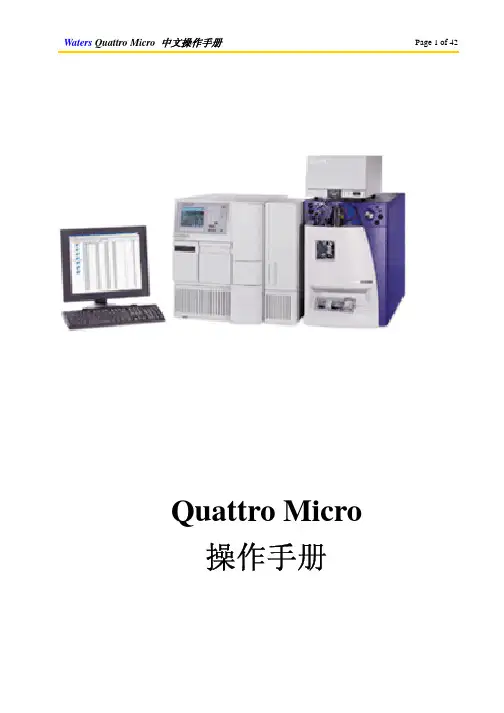
Quattro Micro 操作手册目录开启控制软件MassLynx二、以设定溶液开始质谱调谐,确定质谱仪的状态三、信号提取四、查看文件五、液相色谱操作程序六、测试送检样品之标准操作程序七、子离子扫描模式八、质量校正九、当长时间停电或移机必须关机时,关闭电源,和泄真空的程序一、开启控制软件MassLynx:1. 从桌面以鼠标左键双击MassLynx图示打开文件。
2. 开启后将自动开启的预设页面,如图示:3. 单击质谱调谐图示(MS Tune)以开启质谱控制页面4. 开启后质谱调谐页面如下:5. 该画面即为调谐和信号提取的主要画面。
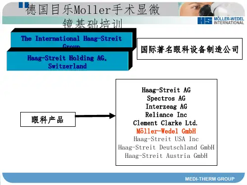
二、以设定溶液(setup solution)开始质谱调谐,确定质谱仪的状态1. 在质谱调谐页面(MS Tune)选择扫描模式和扫描离子质量范围:选中全部四个扫描功能,选择全扫描(MS Scan),设定扫描质量(Mass)为175.1、609.3、1080.8、2034.6,扫描范围(Span)为10(或5)。
2. 以注射针筒抽取设定溶液(setup solution),以直接进样(infusion)的方式连接注射针和管路,让样品得以被注射针泵推送,直接进入质谱仪分析。
3. 在质谱调谐页面(MS Tune)以鼠标左键单击氮气(API GAS)和注射针的图示,接着单击开始操作键(Press for Operate),直到原本红灯的图标显示为绿灯(此时该图标所显示的文字为Press for Standby)。
单击注射针图示则注射针泵会开始运作而推送样品;单击氮气会开始供应三方面的氮气:雾化气体(nebulizing gas)、去溶剂气体(desolvation gas)、气帘气体(cone gas),可以确保样品的气化;而单击操作键之后会开始供应电压,使得样品带电形成离子并使离子通过质谱仪分析。
4. 在质量分析器页面(Analyzer)设定以下的数值,括号内的数值即为设定值:LM Resolution 1(15.0)、HM Resolution 1(15.0)、Ion Energy 1(0.0)、Entrance(50)、Collision(2)、Exit(50)、LM Resolution 2(15.0)、HM Resolution 2(15.0)、Ion Energy 2(3.0),此为配合质谱扫描的参数。



一、培训日程安排1、Real-time PCR原理及应用讲座2、RG3000仪器简介3、仪器安装及使用培训4、定量PCR演示试验5、软件基本功能综述及使用培训二、Rotor Gene3000荧光定量PCR系统介绍Corbett Research公司是著名的专业研制和生产生物仪器的厂家,产品主要包括Rotor-Gene离心式实时定量PCR 仪、CAS-1200 自动加样系统等。
公司自成立以来一直致力于定量PCR 相关仪器的研究开发,将创新技术与精美工艺相结合,在仪器的性能、软件、外观上不断改进,推出临床、科研领域的佼佼者,第一台匀速离心式实时定量PCR 仪—— ROTOR-GENE 3000荧光定量PCR 系统。
1.系统技术参数Rotor-Gene是一套实时显示DNA扩增和杂交过程的循环变温系统。
该装置能在其36孔转子上容纳36个0.2 ml的标准离心管。
72孔转子配有0.1 ml四联管。
2.Rotor-Gene创新的系统结构●独特的离心式设计——最佳的温度均一性反应转子始终都处于低速匀速转动中,保证各样孔相对位置的完全一致。
从而排除因样孔相对位置差异和反应模块边缘效应引起的温度不均一性。
●高效的热力学结构——无需平衡时间升温时,顶部金属加热器加热封闭的反应舱空气,降温时,底部强力排风扇迅速排出热空气,同时打开顶部气孔,达到快速空气交换。
开放式转子设计,保证快速的热交换,相比其它定量PCR系统,运行速度更高。
●巧妙的光学设计——无需ROX内参及光学补偿优化的独立的LED激发光源,保证最小的光谱交叉,离心式的模块保证每个样孔受到完全均一的激发。
●开放的系统——低廉的运行成本适合所有定量PCR标记方法:如Sybr Green, Taqman, MB, FRET, Quenched FRET, Ampliflour等。
开放的试剂系统:无需特定的酶和试剂,使用绝大部分厂家提供的酶和反应体系。
无需内参和特殊反应容器:固定的光程和最小的光学交叉,无需内参校正系统;PCR 管壁检测,普通PCR管即可满足要求。
MicroRotofor TM Cell培训教程Bio-Rad2008年6月目录一、仪器清点和客户实验准备二、实验装置安装和实验操作三、拆卸和清洗四、故障排除五、订货信息一、仪器清点和客户实验准备1. 仪器清点1.1 MicroRotorfor Cel电泳仪主要部件图1 Micro Rotofor分离器的主要部件与附件(1) Micro Rotofor分离器底座与盖子,(2)收集盘,(3) 聚焦槽,(4a) 阴极,(4b)阳极,(5a)阴极膜,(5b)阳极膜,(6)10ml注射器,(7)3ml注射器,(8)镊子,(9)装配支架,(10)密封带,(11)清洁刷,(12)真空软管,(13)真空槽Micro Rotofor分离器底座与盖子图2 底座部件 (1)位于真空腔的组份收集盘,(2)收集配置,(3)致冷区域,(4)电源接口,(5)致冷开关,(6)电源开关,(7)橡胶塞接口1.2用户自备PowerPac HV/PowerPac Unversial电源;真空泵:可以提供22-27 Hg真空度的真空泵都可使用;真空阀和真空管;电解液用于平衡离子交换膜:0.1M H3PO4与0.1M NaOH各6ml;20ul,100ul,1000ul移液器;移液器头;50ml烧杯2. Micro Rotofor TM Cell start kit主要组成试剂盒主要组成如下:Bio-Lyte pH 3-10 两性电解质,10ml(Catalog #163-1112)标准蛋白质样品,1ml(Catalog # 170-2919)藻青蛋白2mg蓝色蛋白pI 4.5-5.5,血色素2mg红色蛋白pI 6.0-7.5,细胞色素 C质2mg 橙色蛋白pI 8.0-9.0聚焦槽(1)阳极膜(阳离子交换膜):2个,在15ml 0.1M H3PO4电解液中平衡阴极膜(阴离子交换膜):2个,在15ml 0.1M NaOH电解液中平衡收集盘(1)样品上样注射器,3ml(1)电解液加载注射器,10ml (1)二、实验装置安装和实验操作2.1 概述1.在特定电解液中平衡离子交换膜过夜(用Start Kit实验可略过此步)2.组装聚焦槽并密封取样出口3.将样品加入到聚焦槽中并密封上样口4.在电极槽中加入电解液5.将聚焦槽放入Micro Rotofor分离器底座,开始等电聚焦6.切断电源,取下盖子并将Micro Rotofor分离器与真空泵相连7.取下聚焦槽上的样品槽盖,并将其与收集装置连接8.将分离的样品组份吸入收集盘(本实验以Micro Rotofor Cell Start Kit 170-2804为例)2.11 离子交换膜的平衡(使用Start Kit可跳过此步)第一次使用的离子交换膜必须在电解液中平衡过夜(表3.1)。
离子交换膜保存在电解液或去离子水中可以循环使用4-5次。
注释:膜在干质状态可无限期保存。
平衡使用后必须保持湿润保存,否则膜易干裂引起电解液向聚焦槽的泄漏。
表3.1 离子交换膜以及其平衡条件其他电解液见6.52.2 组装聚焦装置这步操作中包括如何放置电极膜以及电极槽和聚焦槽的组装。
1.使用去离子水清洗电极膜(离子交换膜)2.分别将阳极膜(红色包装)和阴极膜(黑色包装)嵌入聚焦槽两端(图2)图2 将阳极膜嵌入聚焦槽一端3.将电极槽与聚焦槽组装a.聚焦槽的阳极膜端连接电极的阳极(指示红色端)b.聚焦槽的阴极膜端连接电极的阴极(指示黑色端)4.调节聚焦槽的上样口使其与电极的通气孔成一直线。
(图3)图3使聚焦槽的样品槽口与电极的通气孔成一直线2.3 准备并加载蛋白样品蛋白样品制备:Start Kit中有三种有颜色的蛋白即藻青蛋白(蓝色蛋白),血色素(红色蛋白),细胞色素 C(橙色蛋白)。
混旋样品后,取100ul蛋白样品(600ug),加入150ul Bio-Lyte pH 3-10 两性电解质,最后加入2.75ml去离子水使最终体积到3.0ml。
再混旋使样品溶液混合均匀。
加样:聚焦槽有两排出口,其中一排与电极通风孔成一直线用于加载样品,而与其相对的另外一排出口则用于样品的收集。
在加载样品前将取样口端密封。
加载样品后,加载口端同样要求密封。
1.利用工具附件的模板剪裁核实的密封条带,用于对聚焦槽出口的密封。
见图4。
图4 利用模板剪裁合适长度的密封带2.用密封带密封取样口,见图5。
保证密封带恰好把取样口密封,不要剩余很多否则在仪器振荡时,容易松动,产生泄漏现象。
图5用密封带密封取样口3.用载样注射器吸取3ml样品溶液,从位于聚焦槽中央的载样口上样,至样品溶液全部均匀渗透到各个腔体内(见图6);或者采用在不同载样口上样,至样品溶液在聚焦槽各个腔体分布均匀。
注:在上样过程中注意不要产生气泡,否则样品溶液在各个腔体内分布不均匀。
如果出现气泡,可以将样品吸出,从另外的载样口上样,注意同样不能产生气泡。
图6 在聚焦槽中加载样品4.加载样品后,核实每一个聚焦腔体内是否充满样品溶液,并保证无气泡。
如果存在气泡,将影响后续的分离,因此请按上步措施进行处理。
5.擦干聚焦槽外部,用密封带将上样口密封。
不要使用过长或过宽的密封带,否则在仪器振荡过程中,密封带松动,容易产生溶液泄漏现象。
2.4 聚焦实验1. 首先将致冷装置上的旋钮旋开。
2. 将聚焦装置放入仪器底盘,聚焦槽上样口端和电极通气口端向上。
核实阳极端(红色端)在左,阴极端(黑色端)在右。
Ⅰ轻轻将阳极推入底盘的阳极连接口(见图7)。
Ⅱ将聚焦槽放入致冷模块中并将阴极端轻轻滑入底盘的阴极凹槽中(见8)。
旋转聚焦装置使该装置与底盘凹槽更好吻合;或开动振荡装置,通过轻微振荡使其吻合。
图7将聚焦装置放入仪器底盘的阳极端图8将聚焦装置滑入仪器底盘的阴极凹槽3. 用10ml 注射器向电极中加入电解液(图9)。
注释:可以使用膜的保存液,或者使用新鲜电解液Ⅰ在阳极通气口处(红色),向内加入6ml 0.1M H3PO4电解液Ⅱ在阴极通气口处(黑色),向内加入6ml 0.1M NaOH电解液图9 向阳极加入阳极电解液4加盖致冷装置盖子,并旋紧螺杆。
5.加盖仪器盖子6.连接Micro Rotofor TM分离器底盘后电源线和电源插座7.连接Micro Rotofor TM分离器到真空装置。
(最好在连接中有阀门可以控制。
)注意:在分离结束收集样品时才使用真空装置。
8.将开关“ON”,打开振荡装置9.根据实验需要将致冷开关设置到Ⅰ(10℃)或Ⅱ(20℃),本实验是Ⅱ(20℃),设置为Ⅰ(10℃)时,请将系统平衡约15min后再进行聚焦分离过程。
设置为Ⅱ(20℃)时,可直接使用。
注:用户根据所分离的蛋白设定不同的温度Ⅰ(20℃)适用不要求非变性蛋白质样品,如IEFⅡ(10℃)适用于非变性蛋白质样品,如蛋白质活性和结构分析等Ⅲ关闭致冷系统。
由于仪器运行时会产生大量热量,损害本仪器,不提倡使用。
10.将仪器盖子的电源口端插入电源,并调节到恒功率状态即1W。
如果电源不能满足要求请参照3.5节进行多步恒电压程序。
11.整个聚焦过程大约需要3h。
通过观察电压变化过程,可以指示聚焦是否完成。
如果电压稳定于某一值时,继续聚焦30min后收集组份。
过长的聚焦时间不但不能提高聚焦效果,还会引起pH梯度的下降。
12.同时该聚焦过程可以通过样品中蛋白颜色的分离来观察。
藻青蛋白有三个等电点即4.5、4.7、5.0,向阳极移动,预期在#3腔体中聚焦。
血色素A和血色素C等电点分别是7.1和7.4,向中央移动,预期在#6、#7中聚焦。
细胞色素C,等电点为9.6,向阴极移动,预期在#9或#10中聚焦。
2.5电源条件恒功率推荐使用恒功率进行操作。
下表详细表述了致冷设置信息,室温控制在19-26℃。
多步恒电压如果电源不能使用恒功率参数,请使用限电流下进行多步恒电压操作。
推荐使用恒电流20mA和恒功率2W。
下表对不同体系样品进行了详细的使用分析。
对于含有 2.5mg蛋白质的2% (w/v) Bio-Lyte@pH3-10体系采用致冷设置Ⅰ,或7M尿素、2M硫脲、2mM TBP、4%CHAPS、2%(w/v)Bio-Lyte@pH3-10体系采用致冷设置Ⅱ。
根据蛋白质载样量、两性电解质的含量、pH 范围的不同使用不同的电流范围,并需要不同的分离时间。
表3.4 多步恒电压设置2.6 组份收集为防止样品扩散,聚焦结束后马上收集样品组份。
1.切断电源2.切断振荡器和致冷装置的电源,打开Micro Rotofor TM分离器顶盖3.核实Micro Rotofor TM分离器与真空装置相连,以及收集装置妥当4.打开致冷装置顶盖,用镊子将密封带取下5.打开真空装置6.将聚焦装置小心的从仪器电极连接处取下,该过程始终保持聚焦槽样品槽口端向上(其密封带已经取下)。
7.将聚焦装置放入收集装置顶端见下图。
调整聚焦槽使其成水平,使排针与取样口平行,不要刺破取样口的密封带。
8.双手控制聚焦槽并向下方按下,使排针刺穿取样口的密封膜。
过程中不能堵塞聚焦槽上样口。
同时用双手的拇指将收集盘插入真空装置。
9.继续按压聚焦槽数秒,使分离的样品组份吸入收集盘10.取下收集盘,关闭真空装置11.用注射器或移液器将各组份样品转移到其他容器中三、拆卸和清洗3.1聚焦装置拆洗1.用工具将电极装置与聚焦装置拆卸分离2.用镊子将离子交换膜取出并放入去离子水或各自电解液中进行保存注释:平衡后的离子交换膜要求放在离子水或各自电解液中保存,如果保存不善引起膜的失水,膜将产生龟裂,从而引起电解液渗入聚焦槽,影响分离结果。
3.用去离子水清洗电极装置4.将聚焦槽浸入2%SDS溶液过夜后用去离子水充分清洗3.2收集装置折洗收集结束后马上进行取样针的清洗以保证取样的重复性。
使用温和洗涤剂对针进行清洗。
1.拆卸真空装置与底盘2.旋开螺丝将取样装置从真空装置上取下,先后取下定位模具、排针和排针架3.清洗并晾干定位模具4.用洗瓶清洗排针上的每根取样针5.清洗并晾干真空槽6.检查更换真空垫圈7.组装收集装置四、故障排除4.1 分离过程中蛋白质沉降按其等电点定义,蛋白质等电点时本身不带电荷。
如果蛋白质本身不带电荷,那么其疏水作用力将大于静电排斥力,从而溶解度降低,发生蛋白质沉降。
在等电聚焦分离过程中经常产生“等电点沉降”。
如何维持蛋白质在溶液中的溶解性6.2节给出了一些提示。
在Micro Rotofor分离器分离过程中加入增加蛋白质溶解度的试剂(6.2)由于蛋白质固有溶解度不同,因此对于该问题没有特定的答案,完全依靠经验进行摸索。
采用分析型IEF胶对少量样品进行分析以比较感兴趣蛋白质的溶解性。
降低蛋白质样品的载入量,以保证良好的溶解性。
4.2 影响pH梯度的因素由于样品制备问题、Micro Rotofor分离器的不恰当使用都会产生非线性的pH梯度。