R09P205D中文资料
- 格式:pdf
- 大小:89.59 KB
- 文档页数:3
ConfigED Lite产品手册和ConfigLite 5.x一起使用○c欧陆传动有限公司 2002版权所有权力均受到严格保护。
未有获得欧陆传动有限公司的书面同意,不允许将本文件的任何一部分存储在检索系统中或者以任何形式传播给出去。
为了保证本文件的准确性,尽管做了很大的努力,但仍然有可能在没有事先通知的情况下对文件进行修改和补充,由此导致的损坏、伤害或费用,欧陆传动有限公司不承担责任。
本手册中详细的工序只能由受过充分培训或有经验的人员来操作。
设备的安装、操作和维修应当由合格的人员进行。
一个合格人员是指在技术上是有能力的,熟悉所有的安全信息并且具有安全方面的经验,熟悉设备的操作,了解高电压电气系统危险性。
如果不遵守这些指导可能造成设备损坏或人员伤亡。
如果你不能确保你有资格或你不理解本手册中的一些工续,请联系欧陆传动有限公司的服务部门来请求帮助。
请确认本手册中的手续,包括安装,请确认产品型号和本手册中的一致。
如果发现任何矛盾,请立即联系客户服务中心。
美国印制 RG352747 第六期ConfigED Lite 手册目录第一章 绪论什么是ConfigEDLite ?..................................................................................................................................1 - 1 离线配置..............................................................................................................................................................1 - 1 计算机兼容性.................................................................................................................................................... 1 - 2 第二章 操作 拆包指令..............................................................................................................................................................2 - 1 特殊处理..............................................................................................................................................................2 - 1 第三章 安装与设置安装步骤..............................................................................................................................................................3 - 1 与驱动器通讯....................................................................................................................................................3 - 4 第四章 创建配置打开一个默认配置...........................................................................................................................................4 - 1 显示此配置.........................................................................................................................................................4 - 2 配置参数..............................................................................................................................................................4 - 3 显示参数..............................................................................................................................................................4 - 3 改变参数..............................................................................................................................................................4 - 4 实现连接..............................................................................................................................................................4 - 4 排列功能块.........................................................................................................................................................4 - 5 保存配置..............................................................................................................................................................4 - 6 打开当前配置......................................................................................................................................................4 -7 安装配置...............................................................................................................................................................4 -7 使用“Get lnfo” ....................................................................................................................................................4 -7 安装配置...............................................................................................................................................................4 -8 更新配置...............................................................................................................................................................4 -8 建立配置模块......................................................................................................................................................4 -9 打印配置...............................................................................................................................................................4 -9 第五章 文件配置文件配置...............................................................................................................................................................5 -1 检查文件...............................................................................................................................................................5 -1 打印文件列表.....................................................................................................................................................5 –2 _______________________________________________________________________________ ConfigED Lite 手册 目录-1ConfigED Lite 手册第六章 高级特征模型........................................................................................................................................................................6 -1 建立模型...............................................................................................................................................................6 -1 自动数据录入......................................................................................................................................................6 -3 第七章 故障诊断通信问题...............................................................................................................................................................7 -1 不匹配的波特率.................................................................................................................................................7 -1 波特率设置过高.................................................................................................................................................7 -1 错误的通信端口.................................................................................................................................................7 -1 驱动器P3模式设置错误..................................................................................................................................7 -1 错误信息...............................................................................................................................................................7 -2 第八章 参考功能模块...............................................................................................................................................................8 -1 内部表格链接......................................................................................................................................................8 -1 组合的链接..........................................................................................................................................................8 -2 制图........................................................................................................................................................................8 -3 制图工具...............................................................................................................................................................8 -4 显示选项...............................................................................................................................................................8 -6 详解制图...............................................................................................................................................................8 -6 便条.................................................................................................................................................8 -6 第九章 附录菜单........................................................................................................................................................................9 -1 文件........................................................................................................................................................................9 -1 编辑........................................................................................................................................................................9 -1 命令........................................................................................................................................................................9 -1 窗口........................................................................................................................................................................9 -2 字体........................................................................................................................................................................9 -2 格式........................................................................................................................................................................9 -2 帮助........................................................................................................................................................................9 –2 _______________________________________________________________________________目录-2 ConfigED Lite 手册第一章绪论第一章绪论什么是ConfigED Lite?ConfigED Lite(CE Lite)是一种用来配置欧陆控制器的软件工具。
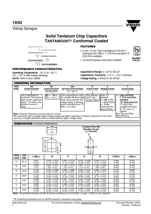
195DVishay SpragueSolid Tantalum Chip Capacitors T ANTAMOUNT ® Conformal CoatedFEATURES•8 mm, 12 mm Tape Packaging to EIA-481-1 reeling per IEC 286-3. 7’ (178 mm) standard 13" (330 mm) available•US and European case sizes availableCapacitance Range: 0.1 µF to 330 µFCapacitance Tolerance: ± 10 %, ± 20 % standard Voltage Rating: 2 WVDC to 50 WVDCPERFORMANCE CHARACTERISTICSOperating Temperature: - 55 °C to + 85 °C (To + 125 °C with voltage derating)NOTE:Refer to Doc 40088ORDERING INFORMATION195D 106X0004S2TT YPECAPACITANCE CAPACITANCE TOLERANCE DC VOLTAGE RATINGAT + 85 °C CASE CODE TERMINATIONPACKAGINGThis is expressed in picofarads. The first two digits are the significant figures. The third is the number of zeros to follow.X0 = ± 20 %X9 = ± 10 %This is expressed in volts. To complete the three-digit block, zeros precede the voltage rating. A decimal point is indicated by an "R" (6R3 = 6.3 volts).See Ratings and Case Codes TableStyle 2 isstandard2 = 100 % Tin4 = Gold Plated8 = SolderPlated (60/40)Special OrderT = Tape and Reel 7" [178 mm] Reel standard 1/2" Reel minimum 13" [330] Reel available excluding the "R" case, on request. See T ape and Reel Specifications.Note: Preferred Tolerance and reel sizes are in bold.We reserve the right to supply higher voltage ratings and tighter capacitance tolerance capacitors in the samecase size. Voltage substitutions will be marked with the higher voltage rating.* Pb containing terminations are nor RoHS compliant, exemptions may apply195DSolid Tantalum Chip Capacitors TANTAMOUNT ® Conformal CoatedVishay SpragueRATINGS AND CASE CODESµF 4 V6.3 V 10 V16 V20 V25 V35 V50 V 0.10 C 0.15 C 0.22C0.33 CS 0.47 CS V0.68C S S V 1.0C S S S X 1.5C S S S V X 2.2C S S S V X Y 3.3C S S S V X Y Z 4.7S S S V X X Z Z 6.8S S V X X Y Z R 10S V X X Y Y Z R 15V X X Y Z Z R 22X X Y Z Z RR33X Y Z Z RR47Y Y Z RR68Y Z RR100Z Z R 120R R R 150R RR180R R 220RR330RSTANDARD RATINGSCAPACITANCE (µF)CASE CODEPART NUMBER*Max. DCL at + 25 °C (µA)Max. DF at + 25 °C 120 Hz (%)4 WVDC AT + 85 °C, SURGE = 5 V . . . 2.7 WVDC AT + 125 °C, SURGE = 3.4 V3.3 C 195D335X_004C2T 0.564.7S 195D475X_004S2T 0.566.8S 195D685X_004S2T 0.5610S 195D106X_004S2T 0.5615V 195D156X_004V2T 0.6622X 195D226X_004X2T 0.9633X 195D336X_004X2T 1.3647Y 195D476X_004Y2T 1.9668Y 195D686X_004Y2T 2.76100Z 195D107X_004Z2T 4.08120R 195D127X_004R2T 4.88150R 195D157X_004R2T 6.08180R 195D187X_004R2T 7.28220R 195D227X_004R2T 8.88330R 195D337X_004R2T 13.28For 10 % tolerance, specify “9“: for 20 % tolerance, change to “0“.195DVishay Sprague Solid Tantalum Chip CapacitorsTANTAMOUNT® Conformal Coated STANDARD RATINGSCAPACITANCE (µF)CASE CODE PART NUMBER*Max. DCLat + 25 °C(µA)Max. DFat + 25 °C120 Hz (%)6.3 WVDC AT + 85 °C, SURGE = 8 V . . . 4 WVDC AT + 125 °C, SURGE = 5 V2.2 C 195D225X_6R3C2T 0.563.3S 195D335X_6R3S2T 0.564.7S 195D475X_6R3S2T 0.566.8S 195D685X_6R3S2T 0.5610V 195D106X_6R3V2T 0.66 15X 195D156X_6R3X2T 0.96 22X 195D226X_6R3X2T 1.36 33Y 195D336X_6R3Y2T 2.06 47Y 195D476X_6R3Y2T 2.86 68Z 195D686X_6R3Z2T 4.16 100Z 195D107X_6R3Z2T 6.08 120R 195D127X_6R3R2T 7.28 150R 195D157X_6R3R2T 9.08 180R 195D187X_6R3R2T 10.88 220R 195D227X_6R3R2T 13.2810 WVDC AT + 85 °C, SURGE = 13V . . . 7 WVDC AT + 125 °C, SURGE = 9 V1.5 C 195D155X_010C2T 0.562.2S 195D225X_010S2T 0.563.3S 195D335X_010S2T 0.564.7S 195D475X_010S2T 0.566.8V 195D685X_010V2T 0.7610X 195D106X_010X2T 1.06 15X 195D156X_010X2T 1.56 22Y 195D226X_010Y2T 2.26 33Z 195D336X_010Z2T 3.06 47Z 195D476X_010Z2T 4.76 68R 195D686X_010R2T 6.86 100R 195D107X_010R2T 108 120R 195D127X_010R2T 128 150R 195D157X_010R2T 15816 WVDC AT + 85 °C, SURGE = 20 V . . . 10 WVDC AT + 125 °C, SURGE = 12 V1.0 C 195D105X_016C2T 0.541.5S 195D155X_016S2T 0.562.2S 195D225X_016S2T 0.563.3S 195D335X_016S2T 0.564.7V 195D475X_016V2T 0.766.8X 195D685X_016X2T 1.0610X 195D106X_016X2T 1.56 15Y 195D156X_016Y2T 2.36 22Z 195D226X_016Z2T 3.36 33Z 195D336X_016Z2T 5.06 47R 195D476X_016R2T 7.16 68R 195D686X_016R2T 10.26 For 10 % tolerance, specify “9“: for 20 % tolerance, change to “0“.195DSolid Tantalum Chip Capacitors TANTAMOUNT ® Conformal CoatedVishay SpragueSTANDARD RATINGSCAPACITANCE (µF)CASE CODEPART NUMBER*Max. DCL at + 25 °C (µA)Max. DF at + 25 °C 120 Hz (%)20 WVDC AT + 85 °C, SURGE = 26 V . . . 13 WVDC AT + 125 °C, SURGE = 16 V0.68 C 195D684X_020C2T 0.541.0S 195D105X_020S2T 0.541.5S 195D155X_020S2T 0.562.2S 195D225X_020S2T 0.563.3V 195D335X_020V2T 0.764.7X 195D475X_020X2T 0.966.8X 195D685X_020X2T 1.4610Y 195D106X_020Y2T 2.0615Z 195D156X_020Z2T 3.0622Z 195D226X_020Z2T 4.4633R 195D336X_020R2T 6.6647R 195D476X_020R2T 9.4625 WVDC AT + 85 °C, SURGE = 32 V . . . 17 WVDC AT + 125 °C, SURGE = 20 V0.47 C 195D474X_025C2T 0.540.68S 195D684X_025S2T 0.541.0S 195D105X_025S2T 0.541.5S 195D155X_025S2T 0.562.2V 195D225X_025V2T 0.663.3X 195D335X_025X2T 0.864.7X 195D475X_025X2T 1.266.8Y 195D685X_025Y2T 1.7610Y 195D106X_025Y2T 2.5615Z 195D156X_025Z2T 3.8622R 195D226X_025R2T 5.5633R 195D336X_025R2T 8.3635 WVDC AT + 85 °C, SURGE = 46 V . . . 23 WVDC AT + 125 °C, SURGE = 28 V0.33 C 195D334X_035C2T 0.540.47S 195D474X_035S2T 0.540.68S 195D684X_035S2T 0.541.0S 195D105X_035S2T 0.541.5V 195D155X_035V2T 0.562.2X 195D225X_035X2T 0.863.3Y 195D335X_035Y2T 1.264.7Z 195D475X_035Z2T 1.666.8Z 195D685X_035Z2T 2.4610Z 195D106X_035Z2T 3.5615R 195D156X_035R2T 5.3622R 195D226X_035R2T 7.76For 10 % tolerance, specify “9“: for 20 % tolerance, change to “0“.195DVishay Sprague Solid Tantalum Chip CapacitorsTANTAMOUNT® Conformal CoatedSTANDARD RATINGSCAPACITANCE (µF)CASE CODE PART NUMBER*Max. DCLat + 25 °C(µA)Max. DFat + 25 °C120 Hz (%)50 WVDC AT + 85 °C, SURGE = 65 V . . . 33 WVDC AT + 125 °C, SURGE = 38 V0.1 C 195D104X_050C2T 0.540.15 C 195D154X_050C2T 0.540.22 C 195D224X_050C2T 0.540.33S 195D334X_050S2T 0.540.47V 195D474X_050V2T 0.540.68V 195D684X_050V2T 0.541.0X 195D105X_050X2T 0.541.5X 195D155X_050X2T 0.862.2Y 195D225X_050Y2T 1.163.3Z 195D335X_050Z2T 1.764.7Z 195D475X_050Z2T 2.466.8R 195D685X_050R2T 3.4610R 195D106X_050R2T 5.06For 10 % tolerance, specify “9“: for 20 % tolerance, change to “0“.195DSolid Tantalum Chip Capacitors TANTAMOUNT ® Conformal CoatedVishay Sprague195DVishay SpragueSolid Tantalum Chip Capacitors TANTAMOUNT ® Conformal CoatedORDERING INFORMATION - EUROPEAN USE ONLY 195D 106X0004D2TT YPE CAPACITANCE CAPACITANCE TOLERANCE DC VOLTAGE RATINGAT + 85 °CCASE CODE TERMINATION PACKAGINGThis is expressed inpicofarads. The first two digits are the significant figures. The third is the number of zeros to follow.X0 = ± 20 %X9 = ± 10 %This is expressed in volts. To complete the three-digit block, zeros precede the voltage rating. A decimal point is indicated by an "R" (6R3 = 6.3 volts).See Ratings and Case Codes TableStyle 2 isstandard2 = SolderableCoating4 = Gold Plated 8 = SolderPlated (60/40)Special OrderT = Tape and Reel 180 mm Reel standard See Tape and Reel Specifications.G Note: The anode termination (D less B) will be a minimum of 0.010 (0.25), C Case = 0.005 (0.131) minimumNote: Preferred Tolerance and reel sizes are in bold.We reserve the right to supply higher voltage ratings and tighter capacitance tolerance capacitors in the same case size. Voltage substitutions will be marked with the higher voltage rating.195DSolid Tantalum Chip CapacitorsTANTAMOUNT® Conformal CoatedVishay Sprague195D STANDARD RANGE, RATINGS AND CASE CODESµF 2 V4 V6.3 V10 V15 V20 V25 V35 V 50 V 0.10A A 0.15A A 0.22A B 0.33AB B 0.47A AB D 0.68A B D D 1.0AB BD E 1.5ABD E F 2.2ABD EF F 3.3A BD EF G 4.7A BD EF G H6.8A D EFG H10AD EFG 15EFG H22FG H33FG H47G H68G H100HSTANDARD RATINGSCAPACITANCE (µF)CASE CODEPART NUMBERMax. DCLat + 25 °C (µA)Max. DF at + 25 °C 120 Hz (%)2 WVDC AT + 85 °C, SURGE = 2.6 V . . . 1.2 WVDC AT + 125 °C, SURGE = 1.6 V3.3 A 195D335X_002A2T 0.584.7 A 195D475X_002A2T 0.586.8 A 195D685X_002A2T 0.5810 A 195D106X_002A2T 0.684 WVDC AT + 85 °C, SURGE = 5 V . . . 2.7 WVDC AT + 125 °C, SURGE = 3.4 V2.2 A 195D225X_004A2T 0.584.7 B 195D475X_004B2T 0.5810 D 195D106X_004D2T 0.5815 E 195D156X_004E2T 0.6833 F 195D336X_004F2T 1.3868G195D686X_004G 2T 2.78100H 195D107X_004H2E 4.086.3 WVDC AT + 85 °C, SURGE = 8 V . . . 4 WVDC AT + 125 °C, SURGE = 5 V1.5 A 195D155X_6R3A2T 0.583.3 B 195D335X_6R3B2T 0.586.8 D 195D685X_6R3D2T 0.5810 E 195D106X_6R3E2T 0.6822 F 195D226X_6R3F2T 1.3847G195D476X_6R3G2T 2.8868H 195D686X_6R3H2E 4.18For 10 % tolerance, specify “9“: for 20 % tolerance, change to “0“.195DVishay SpragueSolid Tantalum Chip Capacitors TANTAMOUNT ® Conformal CoatedSTANDARD RATINGSCAPACITANCE (µF)CASE CODE PART NUMBERMax. DCL at + 25 °C (µA)Max. DF at + 25 °C 120 Hz (%)10 WVDC AT + 85 °C, SURGE = 13 V . . . 7 WVDC AT + 125 °C, SURGE = 9 V1.0 A 195D105X_010A2T 0.562.2 B 195D225X_010B2T 0.564.7 D 195D475X_010D2T 0.566.8 E 195D685X_010E2T 0.7615 F 195D156X_010F2T 1.5647H 195D476X_010H2E 4.7615 / 16 WVDC AT + 85 °C, SURGE = 20 V...10 WVDC AT + 125 °C, SURGE = 12 V0.47 A 195D474X_015A2T 0.560.68 A 195D684X_015A2T 0.561.0 B 195D105X_015B2T 0.561.5 B 195D155X_015B2T 0.563.3 D 195D335X_015D2T 0.564.7 E 195D475X_015E2T 0.7610 F 195D106X_015F2T 1.5622G 195D226X_015G2T 3.3633H 195D336X_015H2E 5.0620 WVDC AT + 85 °C, SURGE = 26 V . . . 13 WVDC AT + 125 °C, SURGE = 16 V0.47 A 195D474X_020A2T 0.561.0 B 195D105X_020B2T 0.562.2 D 195D225X_020D2T 0.563.3 E 195D335X_020E2T 0.766.8 F 195D685X_020F2T 1.4615G 195D156X_020G2T 3.0622H 195D226X_020H2E 4.4625 WVDC AT + 85 °C, SURGE = 32 V . . . 17 WVDC AT + 125 °C, SURGE = 20 V0.33 A 195D334X_025A2T 0.560.68 B 195D684X_025B2T 0.561.5 D 195D155X_025D2T 0.562.2 E 195D225X_025E2T 0.664.7 F 195D475X_025F2T 1.266.8G195D685X_025G2T 1.7610G 195D106X_025G 2T 2.5615H 195D156X_025H2E 3.86For 10 % tolerance, specify “9“: for 20 % tolerance, change to “0“.195DSolid Tantalum Chip Capacitors TANTAMOUNT ® Conformal CoatedVishay SpragueSTANDARD RATINGSCAPACITANCE (µF)CASE CODEPART NUMBERMax. DCL at + 25 °C (µA)Max. DF at + 25 °C 120 Hz (%)35 WVDC AT + 85 °C, SURGE = 46 / 52 V. . . 23 / 25 WVDC AT + 125 °C, SURGE = 28 / 30 V 0.10 A 195D104X_035A2T 0.560.15 A 195D154X_035A2T 0.560.22 A 195D224X_035A2T 0.560.33 B 195D334X_035B2T 0.560.47 B 195D474X_035B2T 0.560.68 D 195D684X_035D2T 0.561.0 D 195D105X_035D2T 0.561.5 E 195D155X_035E2T 0.562.2 F 195D225X_035F2T 0.863.3 F 195D335X_035F2T 1.264.7G195D475X_035G2T 1.666.8H 195D685X_035H2E 2.4650 WVDC AT + 85 °C, SURGE = 65 V . . . 33 WVDC AT + 125 °C, SURGE = 38 V0.10 A 195D104X_050A2T 0.560.15 A 195D154X_050A2T 0.560.22 B 195D224X_050B2T 0.560.33 B 195D334X_050B2T 0.560.47 D 195D474X_050D2T 0.560.68 D 195D684X_050D2T 0.561.0 E 195D105X_050E2T 0.561.5 F 195D155X_050F2T 0.862.2 F 195D225X_050F2T 1.163.3G 195D335X_050G2T 1.764.7H 195D475X_050H2E 2.46For 10 % tolerance, specify “9“: for 20 % tolerance, change to “0“.Legal Disclaimer NoticeVishay Document Number: Revision: 08-Apr-051NoticeSpecifications of the products displayed herein are subject to change without notice. Vishay Intertechnology, Inc., or anyone on its behalf, assumes no responsibility or liability for any errors or inaccuracies.Information contained herein is intended to provide a product description only. No license, express or implied, by estoppel or otherwise, to any intellectual property rights is granted by this document. Except as provided in Vishay's terms and conditions of sale for such products, Vishay assumes no liability whatsoever, and disclaims any express or implied warranty, relating to sale and/or use of Vishay products including liability or warranties relating to fitness for a particular purpose, merchantability, or infringement of any patent, copyright, or other intellectual property right.The products shown herein are not designed for use in medical, life-saving, or life-sustaining applications.Customers using or selling these products for use in such applications do so at their own risk and agree to fully indemnify Vishay for any damages resulting from such improper use or sale.元器件交易网。
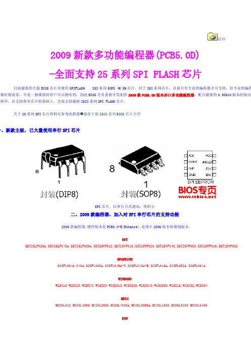
打印2009新款多功能编程器(PCB5.0D)-全面支持25系列SPI FLASH芯片目前最新的主板BIOS芯片多使用SPIFLASH 25X系列SOP8 4M 8M芯片。
对于25X系列芯片,目前只有专业的编程器才可支持,但专业的编程器价格很贵,不是一般维修的用户可以拥有的;因此BIOS专页重新开发制作2009款PCB5.0D版本并口多功能编程器,配合最新的0.98D10版本的驱动程序,在支持原有芯片的基础上,全面支持最新25XX系列SPI FLAHS芯片。
关于25系列SPI芯片资料可参考此联接最新主板25XX系列BIOS芯片介绍一、新款主板,已大量使用串行SPI芯片SPI芯片,以串行方式通讯,体积小二、2009款编程器,加入对SPI串行芯片的支持功能2009款编程器,硬件版本是PCB5.0-E(Enhance),是瑞丰2006版本的增强版本。
SSTSST25LF020A,SST25LF040A,SST25LF080A,SST25VF512,SST25VF010,SST25VF020,SST25VF040,SST25VF080,SST25VF016,SST25VF032SPANSIONS25FL004A/040A,S25FL008A,S25FL040A-T,S25FL040A-B,S25FL016A,S25FL032A S25FL064AWINBONDW25X10,W25X20,W25X40,W25X80 W25X010,W25X020,W25X040,W25X080,W25X16,W25X32,W25X64MXICMX25L512,MX25L1005,MX25L2005,MX25L4005A,MX25L8005A,MX25L1605,MX25L3205 MX25L6405EONEN25B05,EN25B10,EN25B20,EN25B40,EN25B80,EN25B16,EN25B32,EN25B64 EN25P05,EN25P10,EN25P20,EN25P40,EN25BP80,EN25P16EN25P32,EN25P64 EN25D80,EN25D16,EN25F20,EN25F40,EN25F80,EN25F16AMICA25L05P-B,A25L10P-B,A25L20P-B,A25L05P-T,A25L10P-T,A25L20P-T,A25L512,A25L010,A25L020,A25L040,A25L080;,A25L016,A25L032pFLASHPm25LV512,Pm25LV010,Pm25LV020,Pm25LV040,Pm25LV080,Pm25LV016Numonyx (ST)M25P05,M25P10,M25P20,M25P40,M25P80,M25P16,M25P32,M25P64,M25PE10,M25PE20,M25PE40,M25PE80,**M45PE10,M45PE20,M45PE40,M45PE80,M45PE16,M25PX80,M25PX16,M25PX32,M25PX64随着主板上使用的SPI种类及型号的增加,2009款编程器也会逐渐加入对更多芯片的支持。

W25Q64BV出版日期:2010年7月8日- 1 - 版本E64M位与串行闪存双路和四路SPIW25Q64BV- 2 -目录1,一般DESCRIPTION (5)2。
FEATURES (5)3引脚配置SOIC208-MIL.......................................... .. (6)4,焊垫配置WSON8X6-MM.......................................... . (6)5,焊垫配置PDIP300-MIL.......................................... . (7)6引脚说明SOIC208密耳,PDIP300密耳和WSON8X6-MM................................ 7......7引脚配置SOIC300mil的.......................................... .. (8)8引脚SOIC封装说明300-MIL (8)8.1包装Types (9)8.2片选(/CS) (9)8.3串行数据输入,输出和IO(DI,DO和IO0,IO1,IO2,IO3)............................. 9.......8.4写保护(/WP) (9)8.5控股(/HOLD) (9)8.6串行时钟(CLK) (9)9座DIAGRAM (10)10功能DESCRIPTION (11)10.1 SPI OPERATIONS (11)10.1.1标准SPI Instructions (11)10.1.2双SPI Instructions (11)10.1.3四路SPI Instructions (11)10.1.4保持功能 (11)10.2写保护 (12)10.2.1写保护Features (12)11,控制和状态寄存器............................................ .. (13)11.1状态REGISTER (13)11.1.1 BUSY (13)11.1.2写使能锁存(WEL) (13)11.1.3块保护位(BP2,BP1,BP0)..................................... .. (13)11.1.4顶/底块保护(TB)....................................... .................................................. ..1311.1.5部门/块保护(SEC) (13)11.1.6状态寄存器保护(SRP,SRP0)....................................... . (14)11.1.7四路启用(QE) (14)11.1.8状态寄存器内存保护........................................... .. (16)11.2 INSTRUCTIONS (17)11.2.1制造商和设备标识........................................... .. (17)11.2.2指令集表1 (18)W25Q64BV11.2.3指令表2(阅读说明书)....................................... (19)出版日期:2010年7月8日- 3 - 修订版E11.2.4写使能(06h) (20)11.2.5写禁止(04h) (20)11.2.6读状态寄存器1(05H)和读状态寄存器2(35H).............................. (21)11.2.7写状态寄存器(01H)......................................... .................................................. .. (22)11.2.8读取数据(03h) (23)11.2.9快速阅读(0Bh) (24)11.2.10快速读双输出(3BH)........................................ .................................................. 0.25 11.2.11快速读四路输出(6BH)........................................ .. (26)11.2.12快速读双I / O (BBh) (27)11.2.13快速读取四I/ O (EBh) (29)11.2.14八进制字读取四I/ O(E3H)..................................... (31)11.2.15页编程(02h) (33)11.2.16四路输入页编程(32H)........................................ . (34)11.2.17扇区擦除(20H) (35)11.2.1832KB的块擦除(52H) (36)11.2.1964KB的块擦除(D8h) (37)20年2月11日芯片擦除(C7H/ 60h) (38)21年2月11日擦除挂起(75h) (39)22年2月11日擦除恢复(7Ah) (40)23年11月2日掉电(B9h) (41)24年2月11日高性能模式(A3H)......................................... (42)25年2月11日发布掉电或高性能模式/设备ID(ABH) (42)26年2月11日读制造商/设备ID(90H)....................................... . (44)27年2月11日阅读唯一的ID号(4BH)........................................ . (45)28年2月11日读JEDEC的ID (9Fh) (46)29年2月11日连续读取模式复位(FFH或FFFFH)...................................... .. (47)12,电气特性.............................................. (48)12.1绝对最大Ratings (48)12.2操作范围 (48)12.3上电时序和写抑制阈值......................................... (49)12.4直流电气Characteristics (50)12.5 AC测量条件.............................................. .. (51)12.6 AC电气Characteristics (52)12.7 AC电气特性(续)......................................... . (53)12.8串行输出Timing (54)12.9输入Timing (54)12.10持有Timing (54)13包装SPECIFICATION (55)W25Q64BV13.18引脚SOIC208密耳(包装代号SS)..................................... .. (55)- 4 -13.28引脚PDIP300密耳(封装代码DA)..................................... (56)13.38触点WSON8x6毫米(封装代码ZE)....................................... (57)13.416引脚SOIC300密耳(封装代码SF)..................................... . (58)14订货INFORMA TION (59)14.1有效的部件号和顶端标记.......................................... (60)15版本HISTORY (61)W25Q64BV出版日期:2010年7月8日- 5 - 修订版E1概述该W25Q64BV(64M位)串行Flash存储器提供了有限的系统存储解决方案空间,引脚和电源。
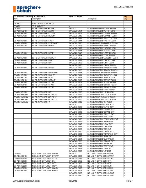
D5 items as currently in the AS400New D7 items Pkg Item Description Description Qty D5-ABZ1PLASTIC SQUARE BEZEL-D5-AB7PB IP66 BOOT-D5-AD2ILL PB DIFFUSER-BLANK D7-AD2ILL PB DIFFUSER BLANK FLUSH10 D5-AD2HE24B ILL PB DIFFUSER 'AUTO'D7-AD2CE101ILL PB DIFFUSER 'AUTO' FLUSH1D5-AD2HE14B ILL PB DIFFUSER 'CLOSE'D7-AD2CE107ILL PB DIFFUSER 'CLOSE' FLUSH1D5-AD2HE13B ILL PB DIFFUSER 'DOWN'D7-AD2CE110ILL PB DIFFUSER 'DOWN' FLUSH1D7-AD2CE113ILL PB DIFFUSER 'FAULT' FLUSH1D5-AD2HE19B ILL PB DIFFUSER 'FAST'D7-AD2CE114ILL PB DIFFUSER 'FAST' FLUSH1D5-AD2HE09B ILL PB DIFFUSER 'FORWARD'D7-AD2CE120ILL PB DIFFUS 'FORWARD' FLUSH1D5-AD2HE23B ILL PB DIFFUSER 'HAND'D7-AD2CE126ILL PB DIFFUSER 'HAND' FLUSH1D7-AD2CE129ILL PB DIFFUSER 'HIGH' FLUSH1D7-AD2CE138ILL PB DIFFUSER 'JOG' FLUSH1D5-AD2HE18B ILL PB DIFFUSER 'LEFT'D7-AD2CE145ILL PB DIFFUSER 'LEFT' FLUSH1D7-AD2CE148ILL PB DIFFUSER 'LOW' FLUSH1D5-AD2HE16B ILL PB DIFFUSER 'LOWER'D7-AD2CE152ILL PB DIFFUSER 'LOWER' FLUSH1D5-AD2HE04B ILL PB DIFFUSER 'OFF'D7-AD2CE163ILL PB DIFFUSER 'OFF' FLUSH1D5-AD2HE03B ILL PB DIFFUSER 'ON'D7-AD2CE166ILL PB DIFFUSER 'ON' FLUSH1D7-AD2CE170ILL PB DIFFUSER 'OPEN' FLUSH1D5-AD2HE15B ILL PB DIFFUSER 'RAISE'D7-AD2CE182ILL PB DIFFUSER 'RAISE' FLUSH1D7-AD2CE185ILL PB DIFFUSER 'READY' FLUSH1D5-AD2HE10B ILL PB DIFFUSER 'REVERSE'D7-AD2CE188ILL PB DIFFUS 'REVERSE' FLUSH1D5-AD2HE17B ILL PB DIFFUSER 'RIGHT'D7-AD2CE191ILL PB DIFFUSER 'RIGHT' FLUSH1D5-AD2HE22B ILL PB DIFFUSER 'RUN'D7-AD2CE193ILL PB DIFFUSER 'RUN' FLUSH1D5-AD2HE21B ILL PB DIFFUSER 'SET-UP'D7-AD2CE198ILL PB DIFFUSER 'SETUP' FLUSH1D5-AD2HE20B ILL PB DIFFUSER 'SLOW'D7-AD2CE201ILL PB DIFFUSER 'SLOW' FLUSH1D5-AD2HE01B ILL PB DIFFUSER 'START'D7-AD2CE208ILL PB DIFFUSER 'START' FLUSH1D5-AD2HE02B ILL PB DIFFUSER 'STOP'D7-AD2CE212ILL PB DIFFUSER 'STOP' FLUSH1D7-AD2CE221ILL PB DIFFUSER 'TRIP' FLUSH1D5-AD2HE12B ILL PB DIFFUSER 'UP'D7-AD2CE223ILL PB DIFFUSER 'UP' FLUSH1D5-AD2HY919B ILL PB DIFFUSER ISO 71 'IO'D7-AD2CU219ILL PB DIFFUS ISO 71'OI' FLUSH1D5-AD2HY909B ILL PB DIFFUSER ISO 69 ' I 'D7-AD2CU909ILL PB DIFFUS ISO 69 ' I ' FLUSH1D5-AD2HY910B ILL PB DIFFUSER ISO 70 'O'D7-AD2CU910ILL PB DIFFUS ISO 70 'O' FLUSH1D5-AD2HY924B ILL PB DIFFUSER ' R 'D7-AD2CU924ILL PB DIFFUSER ' R ' FLUSH1D7-AD4ILL PB DIFFUSER BLANK EXT10D7-AD4CE101ILL PB DIFFUSER 'AUTO' EXT1D7-AD4CE107ILL PB DIFFUSER 'CLOSE' EXT1D7-AD4CE110ILL PB DIFFUSER 'DOWN' EXT1D7-AD4CE113ILL PB DIFFUSER 'FAULT' EXT1D7-AD4CE114ILL PB DIFFUSER 'FAST' EXT1D7-AD4CE120ILL PB DIFFUSER 'FORWARD' EXT1D7-AD4CE129ILL PB DIFFUSER 'HIGH' EXT1D7-AD4CE148ILL PB DIFFUSER 'LOW' EXT1D7-AD4CE163ILL PB DIFFUSER 'OFF' EXT1D7-AD4CE166ILL PB DIFFUSER 'ON' EXT1D7-AD4CE170ILL PB DIFFUSER 'OPEN' EXT1D7-AD4CE188ILL PB DIFFUSER 'REVERSE' EXT1D7-AD4CE193ILL PB DIFFUSER 'RUN' EXT1D7-AD4CE201ILL PB DIFFUSER 'SLOW' EXT1D7-AD4CE208ILL PB DIFFUSER 'START' EXT1D7-AD4CE212ILL PB DIFFUSER 'STOP' EXT1D7-AD4CE219ILL PB DIFFUSER 'TEST' EXT1D7-AD4CE221ILL PB DIFFUSER 'TRIP' EXT1D7-AD4CE223ILL PB DIFFUSER 'UP' EXT1D5-AD3IND LIGHT DIFFUSER BLANK D7-AD3IND LIGHT DIFFUSER BLANK10 D5-AD3HE01B IND LIGHT DIFFUSER 'START'D7-AD3CE208IND LIGHT DIFFUSER 'START'1D5-AD3HE02B IND LIGHT DIFFUSER 'STOP'D7-AD3CE212IND LIGHT DIFFUSER 'STOP'1D5-AD3HE03B IND LIGHT DIFFUSER 'ON'D7-AD3CE166IND LIGHT DIFFUSER 'ON'1D5-AD3HE04B IND LIGHT DIFFUSER 'OFF'D7-AD3CE163IND LIGHT DIFFUSER 'OFF'1D5-AD3HE22B IND LIGHT DIFFUSER 'RUN'D7-AD3CE193IND LIGHT DIFFUSER 'RUN'1D5-AD3HE23B IND LIGHT DIFFUSER 'HAND'D7-AD3CE126IND LIGHT DIFFUSER 'HAND'1D7-AD3CE113IND LIGHT DIFFUSER 'FAULT'1D7-AD3CE120IND LIGHT DIFFUSER 'FORWARD'1D7-AD3CE129IND LIGHT DIFFUSER 'HIGH'1D7-AD3CE138IND LIGHT DIFFUSER 'JOG'1D7-AD3CE148IND LIGHT DIFFUSER 'LOW'1D7-AD3CE170IND LIGHT DIFFUSER 'OPEN'1D7-AD3CE185IND LIGHT DIFFUSER 'READY'1D7-AD3CE186IND LIGHT DIFFUSER 'RESET'1D7-AD3CE188IND LIGHT DIFFUSER 'REVERSE'1D7-AD3CE196IND LIGHT DIFFUSER 'SAFE'1D7-AD3CE201IND LIGHT DIFFUSER 'SLOW'1D7-AD3CE219IND LIGHT DIFFUSER 'TEST'1D7-AD3CE221IND LIGHT DIFFUSER 'TRIP'1D7-AD3CE223IND LIGHT DIFFUSER 'UP'1D7-AD3CE267IND LIGHT DIFFUSER 'OVERLOAD'1D7-AD3CU228IND LIGHT DIFFUSER 'O'1D7-AD3CU229IND LIGHT DIFFUSER 'I'1D7-AD3CU230IND LIGHT DIFFUSER 'II'1D7-AD3CU924IND LIGHT DIFFUSER 'R'1 D5-AD3HE26B IND LIGHT DIFFUSER 'POWER ON'D5-AEL1LOCK ATTACHMENT-EXT-NON ILLD5-AFL1LOCK ATTACHMENT-FLUSH-NON ILLD5-AE1COLOR CAP-WHITE-BLANK EXT D7-AE1PB CAP WHITE BLANK EXT10D7-AE108PB CAP WHITE ARROW SYM EXT10D7-AE111PB CAP WHITE 'R' EXT10D7-AE1CE101PB CAP WHITE 'AUTO' EXT1D7-AE1CE105PB CAP WHITE 'BRAKE' EXT1D7-AE1CE107PB CAP WHITE 'CLOSE' EXT1D7-AE1CE110PB CAP WHITE 'DOWN' EXT1D7-AE1CE114PB CAP WHITE 'FAST' EXT1D7-AE1CE120PB CAP WHITE 'FORWARD' EXT1D7-AE1CE129PB CAP WHITE 'HIGH' EXT1D7-AE1CE138PB CAP WHITE 'JOG' EXT1D7-AE1CE163PB CAP WHITE 'OFF' EXT1D7-AE1CE166PB CAP WHITE 'ON' EXT1D7-AE1CE170PB CAP WHITE 'OPEN' EXT1D7-AE1CE185PB CAP WHITE 'READY' EXT1D7-AE1CE186PB CAP WHITE 'RESET' EXT1D7-AE1CE188PB CAP WHITE 'REVERSE' EXT1D7-AE1CE201PB CAP WHITE 'SLOW' EXT1D7-AE1CE208PB CAP WHITE 'START' EXT1D7-AE1CE212PB CAP WHITE 'STOP' EXT1D7-AE1CE219PB CAP WHITE 'TEST' EXT1D7-AE1CE221PB CAP WHITE 'TRIP' EXT1D7-AE1CE223PB CAP WHITE 'UP' EXT1D7-AE1CU219PB CAP WHITE ISO 71 'OI' EXT1D7-AE1CU228PB CAP WHITE 'O' EXT1D7-AE1CU229PB CAP WHITE 'I' EXT1D7-AE1CU230PB CAP WHITE 'II' EXT1D7-AE1CU924PB CAP WHITE 'R' EXT1 D5-AE2COLOR CAP-BLK-BLANK EXT D7-AE2PB CAP BLACK BLANK EXT10D7-AE202PB CAP BLACK 'STOP' EXT10D7-AE205PB CAP BLACK 'O' EXT10D7-AE208PB CAP BLACK ARROW SYM EXT10D7-AE211PB CAP BLACK 'R' EXT10D7-AE2CE101PB CAP BLACK 'AUTO' EXT1D7-AE2CE105PB CAP BLACK 'BRAKE' EXT1D7-AE2CE107PB CAP BLACK 'CLOSE' EXT1D7-AE2CE110PB CAP BLACK 'DOWN' EXT1D7-AE2CE114PB CAP BLACK 'FAST' EXT1D7-AE2CE120PB CAP BLACK 'FORWARD' EXT1D7-AE2CE166PB CAP BLACK 'ON' EXT1D7-AE2CE170PB CAP BLACK 'OPEN' EXT1D7-AE2CE185PB CAP BLACK 'READY' EXT1D7-AE2CE186PB CAP BLACK 'RESET' EXT1D7-AE2CE188PB CAP BLACK 'REVERSE' EXT1D7-AE2CE201PB CAP BLACK 'SLOW' EXT1D7-AE2CE208PB CAP BLACK 'START' EXT1D7-AE2CE212PB CAP BLACK 'STOP' EXT1D7-AE2CE219PB CAP BLACK 'TEST' EXT1D7-AE2CE221PB CAP BLACK 'TRIP' EXT1D7-AE2CE223PB CAP BLACK 'UP' EXT1D7-AE2CU219PB CAP BLACK ISO 71 'OI' EXT1D7-AE2CU228PB CAP BLACK 'O' EXT1D7-AE2CU229PB CAP BLACK 'I' EXT1D7-AE2CU230PB CAP BLACK 'II' EXT1 D5-AE2HY914W COLOR CAP-BLK ISO 75 EXT D7-AE2CU914PB CAP BLACK ISO 75 SYM EXT1D7-AE2CU924PB CAP BLACK 'R' EXT1 D5-AE3COLOR CAP-GREEN-BLANK EXT D7-AE3PB CAP GREEN BLANK EXT10D7-AE308PB CAP GRN RT ARROW SYM EXT10D7-AE3CE101PB CAP GREEN 'AUTO' EXT1D7-AE3CE105PB CAP GREEN 'BRAKE' EXT1D7-AE3CE107PB CAP GREEN 'CLOSE' EXT1D7-AE3CE110PB CAP GREEN 'DOWN' EXT1D7-AE3CE114PB CAP GREEN 'FAST' EXT1D7-AE3CE120PB CAP GREEN 'FORWARD' EXT1D7-AE3CE129PB CAP GREEN 'HIGH' EXT1D7-AE3CE138PB CAP GREEN 'JOG' EXT1D7-AE3CE163PB CAP GREEN 'OFF' EXT1D7-AE3CE166PB CAP GREEN 'ON' EXT1D7-AE3CE170PB CAP GREEN 'OPEN' EXT1D7-AE3CE185PB CAP GREEN 'READY' EXT1D7-AE3CE186PB CAP GREEN 'RESET' EXT1D7-AE3CE188PB CAP GREEN 'REVERSE' EXT1D7-AE3CE201PB CAP GREEN 'SLOW' EXT1D7-AE3CE208PB CAP GREEN 'START' EXT1D7-AE3CE219PB CAP GREEN 'TEST' EXT1D7-AE3CE221PB CAP GREEN 'TRIP' EXT1D7-AE3CE223PB CAP GREEN 'UP' EXT1D7-AE3CU219PB CAP GREEN ISO 71 'OI' EXT1D7-AE3CU229PB CAP GREEN 'I' EXT1D7-AE3CU230PB CAP GREEN 'II' EXT1D7-AE3CU924PB CAP GREEN 'R' EXT1 D5-AE4COLOR CAP-RED-BLANK EXT D7-AE4PB CAP RED BLANK EXT10D7-AE402PB CAP RED 'STOP' EXT10D7-AE405PB CAP RED 'O' EXT10D7-AE408PB CAP RED ARROW SYM EXT10D7-AE4CE101PB CAP RED 'AUTO' EXT1D7-AE4CE105PB CAP RED 'BRAKE' EXT1D7-AE4CE107PB CAP RED 'CLOSE' EXT1D7-AE4CE110PB CAP RED 'DOWN' EXT1D7-AE4CE114PB CAP RED 'FAST' EXT1D7-AE4CE120PB CAP RED 'FORWARD' EXT1D7-AE4CE129PB CAP RED 'HIGH' EXT1D7-AE4CE138PB CAP RED 'JOG' EXT1 D5-AE4HE04W COLOR CAP-RED 'OFF' EXT D7-AE4CE163PB CAP RED 'OFF' EXT1D7-AE4CE166PB CAP RED 'ON' EXT1D7-AE4CE170PB CAP RED 'OPEN' EXT1D7-AE4CE185PB CAP RED 'READY' EXT1D7-AE4CE186PB CAP RED 'RESET' EXT1D7-AE4CE188PB CAP RED 'REVERSE' EXT1D7-AE4CE201PB CAP RED 'SLOW' EXT1D7-AE4CE221PB CAP RED 'TRIP' EXT1D7-AE4CE223PB CAP RED 'UP' EXT1D7-AE4CU219PB CAP RED ISO 71 'OI' EXT1 D5-AE405W COLOR CAP-RED IEC5008 'O' EXT D7-AE4CU228PB CAP RED 'O' EXT1D7-AE4CU229PB CAP RED 'I' EXT1D7-AE4CU230PB CAP RED 'II' EXT1 D5-AE4HY910W COLOR CAP-RED ISO 70 EXT D7-AE4CU910PB CAP RED ISO 70 'O' EXT1D7-AE4CU924PB CAP RED 'R' EXT1 D5-AE5COLOR CAP-YELLOW-BLANK EXT D7-AE5PB CAP YELLOW BLANK EXT10D7-AE508PB CAP YELLOW ARROW SYM EXT10D7-AE5CE101PB CAP YELLOW 'AUTO' EXT1D7-AE5CE105PB CAP YELLOW 'BRAKE' EXT1D7-AE5CE107PB CAP YELLOW 'CLOSE' EXT1D7-AE5CE110PB CAP YELLOW 'DOWN' EXT1D7-AE5CE114PB CAP YELLOW 'FAST' EXT1D7-AE5CE120PB CAP YELLOW 'FORWARD' EXT1D7-AE5CE129PB CAP YELLOW 'HIGH' EXT1D7-AE5CE138PB CAP YELLOW 'JOG' EXT1D7-AE5CE163PB CAP YELLOW 'OFF' EXT1D7-AE5CE166PB CAP YELLOW 'ON' EXT1D7-AE5CE170PB CAP YELLOW 'OPEN' EXT1D7-AE5CE185PB CAP YELLOW 'READY' EXT1D7-AE5CE186PB CAP YELLOW 'RESET' EXT1D7-AE5CE188PB CAP YELLOW 'REVERSE' EXT1D7-AE5CE201PB CAP YELLOW 'SLOW' EXT1D7-AE5CE208PB CAP YELLOW 'START' EXT1D7-AE5CE212PB CAP YELLOW 'STOP' EXT1D7-AE5CE219PB CAP YELLOW 'TEST' EXT1D7-AE5CE221PB CAP YELLOW 'TRIP' EXT1D7-AE5CE223PB CAP YELLOW 'UP' EXT1D7-AE5CU219PB CAP YELLOW ISO 71 'OI' EXT1D7-AE5CU228PB CAP YELLOW 'O' EXT1D7-AE5CU229PB CAP YELLOW 'I' EXT1D7-AE5CU230PB CAP YELLOW 'II' EXT1D7-AE5CU924PB CAP YELLOW 'R' EXT1 D5-AE6COLOR CAP-BLUE-BLANK EXT D7-AE6PB CAP BLUE BLANK EXT10D7-AE608PB CAP BLUE ARROW SYM EXT10D7-AE611PB CAP BLUE 'R' EXT10D7-AE6CE101PB CAP BLUE 'AUTO' EXT1D7-AE6CE105PB CAP BLUE 'BRAKE' EXT1D7-AE6CE107PB CAP BLUE 'CLOSE' EXT1D7-AE6CE110PB CAP BLUE 'DOWN' EXT1D7-AE6CE114PB CAP BLUE 'FAST' EXT1D7-AE6CE120PB CAP BLUE 'FORWARD' EXT1D7-AE6CE129PB CAP BLUE 'HIGH' EXT1D7-AE6CE138PB CAP BLUE 'JOG' EXT1D7-AE6CE163PB CAP BLUE 'OFF' EXT1D7-AE6CE166PB CAP BLUE 'ON' EXT1D7-AE6CE170PB CAP BLUE 'OPEN' EXT1D7-AE6CE185PB CAP BLUE 'READY' EXT1D7-AE6CE186PB CAP BLUE 'RESET' EXT1D7-AE6CE188PB CAP BLUE 'REVERSE' EXT1D7-AE6CE201PB CAP BLUE 'SLOW' EXT1D7-AE6CE208PB CAP BLUE 'START' EXT1D7-AE6CE212PB CAP BLUE 'STOP' EXT1D7-AE6CE219PB CAP BLUE 'TEST' EXT1D7-AE6CE221PB CAP BLUE 'TRIP' EXT1D7-AE6CE223PB CAP BLUE 'UP' EXT1D7-AE6CU219PB CAP BLUE ISO 71 'OI' EXT1D7-AE6CU228PB CAP BLUE 'O' EXT1D7-AE6CU229PB CAP BLUE 'I' EXT1D5-AF1COLOR CAP-WHITE-BLANK FLUSH D7-AF1PB CAP WHITE BLANK FLUSH10 D5-AF101B COLOR CAP-WHITE 'START' FLUSH D7-AF101PB CAP WHITE 'START' FLUSH10 D5-AF106B COLOR CAP-WHITE IEC5007 'I'D7-AF106PB CAP WHITE 'I' FLUSH10D7-AF108PB CAP WHT RT ARROW SYM FLUSH10D7-AF111PB CAP WHITE 'R' FLUSH10D7-AF1CE101PB CAP WHITE 'AUTO' FLUSH1D7-AF1CE105PB CAP WHITE 'BRAKE' FLUSH1D7-AF1CE107PB CAP WHITE 'CLOSE' FLUSH1D7-AF1CE110PB CAP WHITE 'DOWN' FLUSH1D7-AF1CE114PB CAP WHITE 'FAST' FLUSH1D7-AF1CE120PB CAP WHITE 'FORWARD' FLUSH1D7-AF1CE129PB CAP WHITE 'HIGH' FLUSH1D7-AF1CE138PB CAP WHITE 'JOG' FLUSH1D7-AF1CE163PB CAP WHITE 'OFF' FLUSH1D7-AF1CE166PB CAP WHITE 'ON' FLUSH1D7-AF1CE170PB CAP WHITE 'OPEN' FLUSH1D7-AF1CE185PB CAP WHITE 'READY' FLUSH1D7-AF1CE186PB CAP WHITE 'RESET' FLUSH1D7-AF1CE188PB CAP WHITE 'REVERSE' FLUSH1D7-AF1CE201PB CAP WHITE 'SLOW' FLUSH1D7-AF1CE208PB CAP WHITE 'START' FLUSH1D7-AF1CE212PB CAP WHITE 'STOP' FLUSH1D7-AF1CE219PB CAP WHITE 'TEST' FLUSH1D7-AF1CE221PB CAP WHITE 'TRIP' FLUSH1D7-AF1CE223PB CAP WHITE 'UP' FLUSH1D7-AF1CU219PB CAP WHITE ISO 71 'OI' FLUSH1D7-AF1CU228PB CAP WHITE 'O' FLUSH1D7-AF1CU229PB CAP WHITE 'I' FLUSH1D7-AF1CU230PB CAP WHITE 'II' FLUSH1D7-AF1CU924PB CAP WHITE 'R' FLUSH1 D5-AF2COLOR CAP-BLK-BLANK FLUSH D7-AF2PB CAP BLACK BLANK FLUSH10 D5-AF202W COLOR CAP-BLK 'STOP' FLUSHD5-AF204W COLOR CAP-BLK 'OFF' FLUSHD5-AF205W COLOR CAP-BLK IEC5008 'O'D5-AF207W COLOR CAP-BLK 'RESET' FLUSHD5-AF208W COLOR CAP-BLK 'ARROW' FLUSH D7-AF208PB CAP BLK RT ARROW SYM FLUSH10 D5-AF209W COLOR CAP-BLK 'FORWARD' FLUSHD5-AF210W COLOR CAP-BLK 'REVERSE' FLUSHD5-AF220W COLOR CAP-BLK ISO 72 FLUSHD7-AF211PB CAP BLACK 'R' FLUSH10 D5-AF2HE24W COLOR CAP-BLK 'AUTO' FLUSH D7-AF2CE101PB CAP BLACK 'AUTO' FLUSH1D7-AF2CE105PB CAP BLACK 'BRAKE' FLUSH1 D5-AF2HE14W COLOR CAP-BLK 'CLOSE' FLUSH D7-AF2CE107PB CAP BLACK 'CLOSE' FLUSH1 D5-AF2HE13W COLOR CAP-BLK 'DOWN' FLUSH D7-AF2CE110PB CAP BLACK 'DOWN' FLUSH1 D5-AF2HE19W COLOR CAP-BLK 'FAST' FLUSH D7-AF2CE114PB CAP BLACK 'FAST' FLUSH1 D5-AF2HE09W COLOR CAP-BLK 'FORWARD' FLUSH D7-AF2CE120PB CAP BLACK 'FORWARD' FLUSH1 D5-AF2HE23W COLOR CAP-BLK 'HAND' FLUSH D7-AF2CE126PB CAP BLACK 'HAND' FLUSH1D7-AF2CE129PB CAP BLACK 'HIGH' FLUSH1D7-AF2CE138PB CAP BLACK 'JOG' FLUSH1 D5-AF2HE18W COLOR CAP-BLK 'LEFT' FLUSH D7-AF2CE145PB CAP BLACK 'LEFT' FLUSH1 D5-AF2HE16W COLOR CAP-BLK 'LOWER' FLUSH D7-AF2CE152PB CAP BLACK 'LOWER' FLUSH1D7-AF2CE163PB CAP BLACK 'OFF' FLUSH1D7-AF2CE166PB CAP BLACK 'ON' FLUSH1 D5-AF2HE05W COLOR CAP-BLK 'OPEN' FLUSH D7-AF2CE170PB CAP BLACK 'OPEN' FLUSH1 D5-AF2HE15W COLOR CAP-BLK 'RAISE' FLUSH D7-AF2CE182PB CAP BLACK 'RAISE' FLUSH1D7-AF2CE185PB CAP BLACK 'READY' FLUSH1D7-AF2CE186PB CAP BLACK 'RESET' FLUSH1 D5-AF2HE10W COLOR CAP-BLK 'REVERSE' FLUSH D7-AF2CE188PB CAP BLACK 'REVERSE' FLUSH1 D5-AF2HE17W COLOR CAP-BLK 'RIGHT' FLUSH D7-AF2CE191PB CAP BLACK 'RIGHT' FLUSH1 D5-AF2HE22W COLOR CAP-BLK 'RUN' FLUSH D7-AF2CE193PB CAP BLACK 'RUN' FLUSH1D7-AF2CE212PB CAP BLACK 'STOP' FLUSH1D7-AF2CE219PB CAP BLACK 'TEST' FLUSH1D7-AF2CE221PB CAP BLACK 'TRIP' FLUSH1 D5-AF2HE12W COLOR CAP-BLK 'UP' FLUSH D7-AF2CE223PB CAP BLACK 'UP' FLUSH1D7-AF2CU219PB CAP BLACK ISO 71 'OI' FLUSH1D7-AF2CU228PB CAP BLACK 'O' FLUSH1D7-AF2CU229PB CAP BLACK 'I' FLUSH1D7-AF2CU230PB CAP BLACK 'II' FLUSH1D7-AF2CU924PB CAP BLACK 'R' FLUSH1 D5-AF3COLOR CAP-GREEN-BLANK FLUSH D7-AF3PB CAP GREEN BLANK FLUSH10 D5-AF301W COLOR CAP-GREEN 'START' FLUSH D7-AF301PB CAP GREEN 'START' FLUSH10 D5-AF303W COLOR CAP-GREEN 'ON' FLUSHD5-AF306W COLOR CAP-GREEN IEC5007 'I'D7-AF306PB CAP GREEN 'I' FLUSH10D7-AF308PB CAP GRN RT ARROW SYM FLUSH10 D5-AF321W COLOR CAP-GRN ISO 5232 'START'D7-AF3CE101PB CAP GREEN 'AUTO' FLUSH1D7-AF3CE105PB CAP GREEN 'BRAKE' FLUSH1D7-AF3CE107PB CAP GREEN 'CLOSE' FLUSH1D7-AF3CE110PB CAP GREEN 'DOWN' FLUSH1D7-AF3CE114PB CAP GREEN 'FAST' FLUSH1D7-AF3CE120PB CAP GREEN 'FORWARD' FLUSH1D7-AF3CE129PB CAP GREEN 'HIGH' FLUSH1D7-AF3CE138PB CAP GREEN 'JOG' FLUSH1D7-AF3CE163PB CAP GREEN 'OFF' FLUSH1D7-AF3CE166PB CAP GREEN 'ON' FLUSH1D7-AF3CE170PB CAP GREEN 'OPEN' FLUSH1D7-AF3CE185PB CAP GREEN 'READY' FLUSH1D7-AF3CE186PB CAP GREEN 'RESET' FLUSH1D7-AF3CE188PB CAP GREEN 'REVERSE' FLUSH1D7-AF3CE201PB CAP GREEN 'SLOW' FLUSH1D7-AF3CE208PB CAP GREEN 'START' FLUSH1D7-AF3CE219PB CAP GREEN 'TEST' FLUSH1D7-AF3CE221PB CAP GREEN 'TRIP' FLUSH1D7-AF3CE223PB CAP GREEN 'UP' FLUSH1D7-AF3CU219PB CAP GREEN ISO 71 'OI' FLUSH1D7-AF3CU229PB CAP GREEN 'I' FLUSH1 D5-AF3HY602W COLOR CAP-GREEN 'II' FLUSH D7-AF3CU230PB CAP GREEN 'II' FLUSH1 D5-AF3HY909W COLOR CAP-GREEN ISO 69 FLUSH D7-AF3CU909PB CAP GREEN ISO 69 'I' FLUSH1D7-AF3CU924PB CAP GREEN 'R' FLUSH1 D5-AF4COLOR CAP-RED-BLANK FLUSH D7-AF4PB CAP RED BLANK FLUSH10 D5-AF402W COLOR CAP-RED 'STOP' FLUSHD5-AF404W COLOR CAP-RED 'OFF' FLUSHD5-AF405W COLOR CAP-RED IEC5008 'O'D5-AF407W COLOR CAP-RED 'RESET' FLUSHD7-AF408PB CAP RED RT ARROW SYM FLUSH10D7-AF4CE105PB CAP RED 'BRAKE' FLUSH1D7-AF4CE107PB CAP RED 'CLOSE' FLUSH1D7-AF4CE110PB CAP RED 'DOWN' FLUSH1D7-AF4CE114PB CAP RED 'FAST' FLUSH1D7-AF4CE120PB CAP RED 'FORWARD' FLUSH1D7-AF4CE129PB CAP RED 'HIGH' FLUSH1D7-AF4CE138PB CAP RED 'JOG' FLUSH1D7-AF4CE163PB CAP RED 'OFF' FLUSH1D7-AF4CE166PB CAP RED 'ON' FLUSH1D7-AF4CE170PB CAP RED 'OPEN' FLUSH1D7-AF4CE185PB CAP RED 'READY' FLUSH1D7-AF4CE186PB CAP RED 'RESET' FLUSH1D7-AF4CE188PB CAP RED 'REVERSE' FLUSH1D7-AF4CE201PB CAP RED 'SLOW' FLUSH1D7-AF4CE208PB CAP RED 'START' FLUSH1D7-AF4CE212PB CAP RED 'STOP' FLUSH1D7-AF4CU228PB CAP RED 'O' FLUSH1D7-AF4CU229PB CAP RED 'I' FLUSH1D7-AF4CU230PB CAP RED 'II' FLUSH1D7-AF4CU910PB CAP RED ISO 70 'O' FLUSH1D7-AF4CU924PB CAP RED 'R' FLUSH1 D5-AF5COLOR CAP-YELLOW-BLANK FLUSH D7-AF5PB CAP YELLOW BLANK FLUSH10D7-AF508PB CAP YEL RT ARROW SYM FLUSH10D7-AF5CE101PB CAP YELLOW 'AUTO' FLUSH1D7-AF5CE105PB CAP YELLOW 'BRAKE' FLUSH1D7-AF5CE107PB CAP YELLOW 'CLOSE' FLUSH1D7-AF5CE110PB CAP YELLOW 'DOWN' FLUSH1D7-AF5CE114PB CAP YELLOW 'FAST' FLUSH1D7-AF5CE120PB CAP YELLOW 'FORWARD' FLUSH1D7-AF5CE129PB CAP YELLOW 'HIGH' FLUSH1D7-AF5CE138PB CAP YELLOW 'JOG' FLUSH1D7-AF5CE163PB CAP YELLOW 'OFF' FLUSH1D7-AF5CE166PB CAP YELLOW 'ON' FLUSH1D7-AF5CE170PB CAP YELLOW 'OPEN' FLUSH1D7-AF5CE185PB CAP YELLOW 'READY' FLUSH1D7-AF5CE186PB CAP YELLOW 'RESET' FLUSH1D7-AF5CE188PB CAP YELLOW 'REVERSE' FLUSH1D7-AF5CE201PB CAP YELLOW 'SLOW' FLUSH1D7-AF5CE208PB CAP YELLOW 'START' FLUSH1D7-AF5CE212PB CAP YELLOW 'STOP' FLUSH1D7-AF5CE219PB CAP YELLOW 'TEST' FLUSH1D7-AF5CE221PB CAP YELLOW 'TRIP' FLUSH1D7-AF5CE223PB CAP YELLOW 'UP' FLUSH1D7-AF5CU229PB CAP YELLOW 'I' FLUSH1D7-AF5CU230PB CAP YELLOW 'II' FLUSH1D7-AF5CU924PB CAP YELLOW 'R' FLUSH1 D5-AF6COLOR CAP-BLUE-BLANK FLUSH D7-AF6PB CAP BLUE BLANK FLUSH10 D5-AF607W COLOR CAP-BLUE 'RESET' FLUSHD7-AF608PB CAP BLUE RT ARROW SYM FLUSH10 D5-AF611W COLOR CAP-BLUE 'R' FLUSH D7-AF611PB CAP BLUE 'R' FLUSH10 D5-AF8COLOR CAP-GRAY-BLANK FLUSHD7-AEU1MULT PB CAP WHITE BLANK EXT10D7-AEU2MULT PB CAP BLACK BLANK EXT10D7-AEU3MULT PB CAP GREEN BLANK EXT10 D5-AEU4MULTI PB CAP-RED-BLANK EXT D7-AEU4MULT PB CAP RED BLANK EXT10D7-AEU5MULT PB CAP YELLOW BLANK EXT10D7-AEU6MULT PB CAP BLUE BLANK EXT10D7-AEAU1CE107MULT PB CAP WHITE 'CLOSE' EXT1D7-AEAU1CE110MULT PB CAP WHITE 'DOWN' EXT1D7-AEAU1CE114MULT PB CAP WHITE 'FAST' EXT1D7-AEAU1CE120MULT PB CAP WHT 'FORWARD' EXT1D7-AEAU1CE129MULT PB CAP WHITE 'HIGH' EXT1D7-AEAU1CE138MULT PB CAP WHITE 'JOG' EXT1D7-AEAU1CE163MULT PB CAP WHITE 'OFF' EXT1D7-AEAU1CE166MULT PB CAP WHITE 'ON' EXT1D7-AEAU1CE170MULT PB CAP WHITE 'OPEN' EXT1D7-AEAU1CE182MULT PB CAP WHITE 'RAISE' EXT1D7-AEAU1CE188MULT PB CAP WHT 'REVERSE' EXT1D7-AEAU1CE201MULT PB CAP WHITE 'SLOW' EXT1D7-AEAU1CE208MULT PB CAP WHITE 'START' EXT1D7-AEAU1CE212MULT PB CAP WHITE 'STOP' EXT1D7-AEAU1CU219MULT PB CAP WHT ISO 71'OI' EXT1D7-AEAU1CU228MULT PB CAP WHITE 'O' EXT1D7-AEAU1CU229MULT PB CAP WHITE 'I' EXT1D7-AEAU1CU230MULT PB CAP WHITE 'II' EXT1D7-AEAU2CE107MULT PB CAP BLACK 'CLOSE' EXT1D7-AEAU2CE129MULT PB CAP BLACK 'HIGH' EXT1D7-AEAU2CE138MULT PB CAP BLACK 'JOG' EXT1D7-AEAU2CE163MULT PB CAP BLACK 'OFF' EXT1D7-AEAU2CE166MULT PB CAP BLACK 'ON' EXT1D7-AEAU2CE170MULT PB CAP BLACK 'OPEN' EXT1D7-AEAU2CE188MULT PB CAP BLK 'REVERSE' EXT1D7-AEAU2CE201MULT PB CAP BLACK 'SLOW' EXT1D7-AEAU2CE208MULT PB CAP BLACK 'START' EXT1D7-AEAU2CE212MULT PB CAP BLACK 'STOP' EXT1D7-AEAU2CU219MULT PB CAP WHT ISO 71'OI' EXT1D7-AEAU2CU228MULT PB CAP BLACK 'O' EXT1D7-AEAU2CU229MULT PB CAP BLACK 'I' EXT1D7-AEAU2CU230MULT PB CAP BLACK 'II' EXT1D7-AEAU3CE107MULT PB CAP GREEN 'CLOSE' EXT1D7-AEAU3CE110MULT PB CAP GREEN 'DOWN' EXT1D7-AEAU3CE114MULT PB CAP GREEN 'FAST' EXT1D7-AEAU3CE120MULT PB CAP GRN 'FORWARD' EXT1D7-AEAU3CE129MULT PB CAP GREEN 'HIGH' EXT1D7-AEAU3CE138MULT PB CAP GREEN 'JOG' EXT1D7-AEAU3CE163MULT PB CAP GREEN 'OFF' EXT1D7-AEAU3CE166MULT PB CAP GREEN 'ON' EXT1D7-AEAU3CE170MULT PB CAP GREEN 'OPEN' EXT1D7-AEAU3CE188MULT PB CAP GRN 'REVERSE' EXT1D7-AEAU3CE201MULT PB CAP GREEN 'SLOW' EXT1D7-AEAU3CE208MULT PB CAP GREEN 'START' EXT1D7-AEAU3CE212MULT PB CAP GREEN 'STOP' EXT1D7-AEAU3CU219MULT PB CAP WHT ISO 71'OI' EXT1D7-AEAU3CU228MULT PB CAP GREEN 'O' EXT1D7-AEAU3CU229MULT PB CAP GREEN 'I' EXT1D7-AEAU3CU230MULT PB CAP GREEN 'II' EXT1D7-AEAU4CE107MULT PB CAP RED 'CLOSE' EXT1D7-AEAU4CE110MULT PB CAP RED 'DOWN' EXT1D7-AEAU4CE114MULT PB CAP RED 'FAST' EXT1D7-AEAU4CE120MULT PB CAP RED 'FORWARD' EXT1D7-AEAU4CE129MULT PB CAP RED 'HIGH' EXT1D7-AEAU4CE138MULT PB CAP RED 'JOG' EXT1 D5-AEUA4PE04W MULTI PB CAP-RED 'OFF' EXT D7-AEAU4CE163MULT PB CAP RED 'OFF' EXT1D7-AEAU4CE166MULT PB CAP RED 'ON' EXT1D7-AEAU4CE170MULT PB CAP RED 'OPEN' EXT1D7-AEAU4CE188MULT PB CAP RED 'REVERSE' EXT1D7-AEAU4CE201MULT PB CAP RED 'SLOW' EXT1D7-AEAU4CE208MULT PB CAP RED 'START' EXT1 D5-AEUA4PE02W MULTI PB CAP-RED 'STOP' EXT D7-AEAU4CE212MULT PB CAP RED 'STOP' EXT1D7-AEAU4CU219MULT PB CAP RED ISO 71'OI' EXT1D7-AEAU4CU228MULT PB CAP RED 'O' EXT1D7-AEAU4CU229MULT PB CAP RED 'I' EXT1D7-AEAU4CU230MULT PB CAP RED 'II' EXT1 D5-AEUA4PY910W MULTI PB CAP- RED ISO 70 EXT D7-AEAU4CU910MULT PB CAP RED ISO 70 'O' EXT1D7-AEAU5CE107MULT PB CAP YELLOW 'CLOSE' EXT1D7-AEAU5CE110MULT PB CAP YELLOW 'DOWN' EXT1D7-AEAU5CE114MULT PB CAP YELLOW 'FAST' EXT1D7-AEAU5CE120MULT PB CAP YEL 'FORWARD' EXT1D7-AEAU5CE129MULT PB CAP YELLOW 'HIGH' EXT1D7-AEAU5CE138MULT PB CAP YELLOW 'JOG' EXT1D7-AEAU5CE163MULT PB CAP YELLOW 'OFF' EXT1D7-AEAU5CE166MULT PB CAP YELLOW 'ON' EXT1D7-AEAU5CE170MULT PB CAP YELLOW 'OPEN' EXT1D7-AEAU5CE188MULT PB CAP YEL 'REVERSE' EXT1D7-AEAU5CE201MULT PB CAP YELLOW 'SLOW' EXT1D7-AEAU5CE208MULT PB CAP YELLOW 'START' EXT1D7-AEAU5CE212MULT PB CAP YELLOW 'STOP' EXT1D7-AEAU5CU230MULT PB CAP YELLOW 'II' EXT1 D7-AEAU6CE107MULT PB CAP BLUE 'CLOSE' EXT1 D7-AEAU6CE110MULT PB CAP BLUE 'DOWN' EXT1 D7-AEAU6CE114MULT PB CAP BLUE 'FAST' EXT1 D7-AEAU6CE120MULT PB CAP BLUE 'FORWARD' EXT1 D7-AEAU6CE129MULT PB CAP BLUE 'HIGH' EXT1 D7-AEAU6CE138MULT PB CAP BLUE 'JOG' EXT1 D7-AEAU6CE163MULT PB CAP BLUE 'OFF' EXT1 D7-AEAU6CE166MULT PB CAP BLUE 'ON' EXT1 D7-AEAU6CE170MULT PB CAP BLUE 'OPEN' EXT1 D7-AEAU6CE188MULT PB CAP BLUE 'REVERSE' EXT1 D7-AEAU6CE201MULT PB CAP BLUE 'SLOW' EXT1 D7-AEAU6CE208MULT PB CAP BLUE 'START' EXT1 D7-AEAU6CE212MULT PB CAP BLUE 'STOP' EXT1 D7-AEAU6CU219MULT PB CAP BLUE ISO 71'OI' EXT1 D7-AEAU6CU228MULT PB CAP BLUE 'O' EXT1 D7-AEAU6CU229MULT PB CAP BLUE 'I' EXT1 D7-AEAU6CU230MULT PB CAP BLUE 'II' EXT1 D7-AECU1CE107MULT PB CAP WHITE 'CLOSE' EXT1 D7-AECU1CE110MULT PB CAP WHITE 'DOWN' EXT1 D7-AECU1CE114MULT PB CAP WHITE 'FAST' EXT1 D7-AECU1CE120MULT PB CAP WHT 'FORWARD' EXT1 D7-AECU1CE129MULT PB CAP WHITE 'HIGH' EXT1 D7-AECU1CE138MULT PB CAP WHITE 'JOG' EXT1 D7-AECU1CE163MULT PB CAP WHITE 'OFF' EXT1 D7-AECU1CE166MULT PB CAP WHITE 'ON' EXT1 D7-AECU1CE170MULT PB CAP WHITE 'OPEN' EXT1 D7-AECU1CE188MULT PB CAP WHT 'REVERSE' EXT1 D7-AECU1CE201MULT PB CAP WHITE 'SLOW' EXT1 D7-AECU1CE208MULT PB CAP WHITE 'START' EXT1 D7-AECU1CE212MULT PB CAP WHITE 'STOP' EXT1 D7-AECU1CU219MULT PB CAP WHT ISO 71'OI' EXT1 D7-AECU1CU228MULT PB CAP WHITE 'O' EXT1 D7-AECU1CU229MULT PB CAP WHITE 'I' EXT1 D7-AECU1CU230MULT PB CAP WHITE 'II' EXT1 D7-AECU2CE107MULT PB CAP BLACK 'CLOSE' EXT1 D7-AECU2CE110MULT PB CAP BLACK 'DOWN' EXT1 D7-AECU2CE114MULT PB CAP BLACK 'FAST' EXT1 D7-AECU2CE120MULT PB CAP BLK 'FORWARD' EXT1 D7-AECU2CE129MULT PB CAP BLACK 'HIGH' EXT1 D7-AECU2CE138MULT PB CAP BLACK 'JOG' EXT1 D7-AECU2CE163MULT PB CAP BLACK 'OFF' EXT1 D7-AECU2CE166MULT PB CAP BLACK 'ON' EXT1 D7-AECU2CE170MULT PB CAP BLACK 'OPEN' EXT1 D7-AECU2CE188MULT PB CAP BLK 'REVERSE' EXT1 D7-AECU2CE201MULT PB CAP BLACK 'SLOW' EXT1 D7-AECU2CE208MULT PB CAP BLACK 'START' EXT1 D7-AECU2CE212MULT PB CAP BLACK 'STOP' EXT1 D7-AECU2CU219MULT PB CAP WHT ISO 71'OI' EXT1 D7-AECU2CU228MULT PB CAP BLACK 'O' EXT1 D7-AECU2CU229MULT PB CAP BLACK 'I' EXT1 D7-AECU2CU230MULT PB CAP BLACK 'II' EXT1 D7-AECU3CE107MULT PB CAP GREEN 'CLOSE' EXT1 D7-AECU3CE110MULT PB CAP GREEN 'DOWN' EXT1 D7-AECU3CE114MULT PB CAP GREEN 'FAST' EXT1 D7-AECU3CE120MULT PB CAP GRN 'FORWARD' EXT1 D7-AECU3CE129MULT PB CAP GREEN 'HIGH' EXT1 D7-AECU3CE138MULT PB CAP GREEN 'JOG' EXT1 D7-AECU3CE163MULT PB CAP GREEN 'OFF' EXT1 D7-AECU3CE166MULT PB CAP GREEN 'ON' EXT1 D7-AECU3CE170MULT PB CAP GREEN 'OPEN' EXT1。
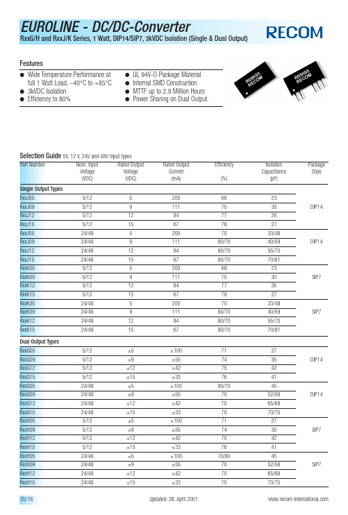
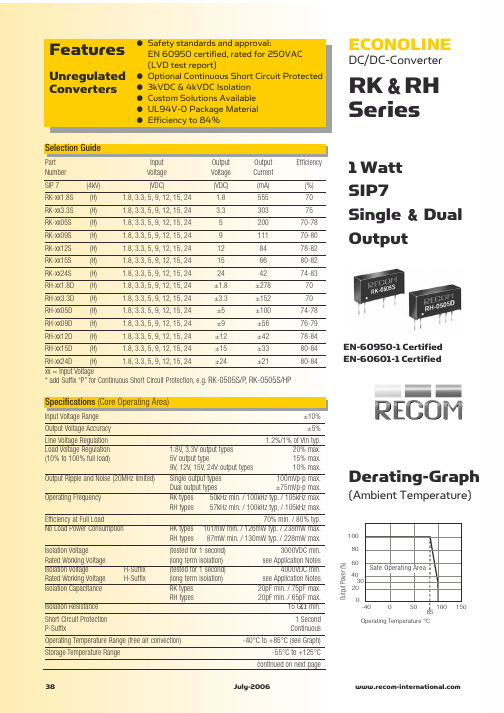
Dual Output TypesRxxG055/12±5±1007127RxxG095/12±9±557435DIP14 RxxG125/12±12±427542RxxG155/12±15±337641RxxG0524/48±5±10080/7045RxxG0924/48±9±557052/58DIP14 RxxG1224/48±12±427065/68RxxG1524/48±15±337070/75RxxH055/12±5±1007127RxxH095/12±9±557435SIP7 RxxH125/12±12±427542RxxH155/12±15±337641RxxH0524/48±5±10070/8045RxxH0924/48±9±557052/58SIP7 RxxH1224/48±12±427065/68RxxH1524/48±15±337070/75Absolute Maximum RatingsInput Voltage V IN5V types 7V typ.12V types 15V typ.24V types 24V typ.48V types48V typ.Short Circuit Duration 1)1s Internal Power Dissipation560mW Lead Temperature (1.5 mm from case for 10 seconds)300 °C1).Supply voltage must be discontinued at the end of the short circuit duration.Input Voltage Range V IN (continuous operation)5V input types 4.5VDC min./ 5.5VDC max.12V input types 10.8VDC min./ 13.2VDC max.24V input types 28VDC max.48V input types54VDC max.Reflected Ripple Current (depending on the type)20 mA p-p min.to 40 mA p-p max.Voltage Set Point Accuracy See Tolerance EnvelopeLine Regulation1.0% / 1.2% of V INLoad Voltage Regulation (10% load to 100% full load)single output types 6.7% min./ 15% max.dual output types 6.8% min./ 10% max.Ripple & Noise (20MHz band limited)single output types 32mVp-p min./ 80mVp-p max.dual output types24mVp-p min./ 40mVp-p max.Isolation Voltage (for 1 minute)3000VDC min.Test Voltage (50Hz,10 seconds)3000 Vpk min.Resistance (Viso = 1000V)10 G Ωtyp.Switching Frequency at Full Load (depending on the type)V IN 5V output types 120kHz min./ 135kHz max.V IN 12V output types 150kHz min./ 170kHz max.V IN 24V output types 150kHz max.V IN 48V output types150kHz max.Package Weight2.11 gOperating Temperature Range (all output types)–40°C min.to +85°C max.(see graph)Storage Temperature Range–50°C min.+125°C max.Case Temperature Above Ambient (depending on the type)5V output types+28°C max.all other output types +25°C max.MTTF 1) (depending on the type)–40°C,single output types 303kHrs min./ 2938kHrs max.+25°C,single output types 252kHrs min./ 2414kHrs max.+85°C,single output types 212kHrs min./ 1961kHrs max.–40°C,dual output types 185kHrs min./ 2068kHrs max.+25°C,dual output types 154kHrs min./ 1697kHrs max.+85°C,dual output types130kHrs min./ 1368kHrs max.1).Calculated using MIL-HDBK-217F with nominal input voltage at full load.Please contact us,if you need exact parameters for the converter you have selected.Electrical Specifications (measured at T A = 25°C,at nominal input voltage and rated output current unless otherwise specified)Package Style and Pinning (mm)。
工程精灵205说明书关于工程精灵工程精灵〔Engineering Genius 2005〕是南方〝测绘通〞软件系列的产品之一。
它基于掌上电脑〔PDA〕,面向工程测量现场,为工放样、曲线测设、纵横断面测量、土石方运算、坐标转换、导线测量、水准测量测量等工作提供数据采集、数据运算、图形绘制的手段与工具。
是为工程测量技术人员量身定制的可视化程度极高的数据工具。
关于本手册本手册对工程精灵的安装、使用方法及有关技巧进行了详细的介绍。
用户应该认真阅读,并边读边用,以求达到软件的最正确使用成效。
本手册版权归南方测绘仪器公司。
在著作权爱护的范畴内,未经本公司书面同意,禁止对其进行翻印、改编等行为。
关于PDA产品本身的使用问题,用户可直截了当阅读PDA产品的使用说明书。
本手册不提供这方面的详细资料。
版权及注册商标AutoCAD、Arc/Info、MapInfo、WinCE、Nikon、Leica、Geodimeter、Sokkia、Topcon、Pentax、清华山维等分别为软、硬件产品和相关公司的专用名称或注册商标,本手册仅为引用。
本公司相关产品作为政府信息产业部门认定的软件企业,南方测绘仪器公司一直致力于以测绘为中心的地理信息采集、成图及治理软件的开发与方案提供。
目前,公司的要紧软件产品有:CASS6.0是本公司开发的数字化地势地籍成图软件。
CASS6.0是CASS的最新升级版本。
CLC为本公司开发的基于MapINFO平台的地籍信息治理专用软件,已在土地行业得到了广泛的应用。
SHIS是本公司开发的集测绘采集、面积分摊、信息治理、房产成图、房产打印等功能于一体的房产信息系统。
该产品已广泛应用于房产测绘与治理部门。
Casscan为本公司的地图扫描矢量化专用软件,要紧用于栅格地图的矢量化处理,是已有白纸地图进入GIS的必备软件,它与CASS具有完美的结合。
平差易〔PA 2005〕是本公司开发的测绘数据平差处理软件,具有方便、易用的特点。

©2020 宁波得力集团有限公司感谢您选购得力产。
品力产品对您使用得力系列产品我们表示衷心的感谢!为了保障您的切身权益,请认真阅读下面的声明内容。
产品外观请以实物为准(P2000、P2020系列产品各型号外观存在差异)。
如需更多帮助请登录:用户手册P2000系列P2020系列黑白激光多功能一体机·“ ”表示支持,“ ”表示不支持。
··如有产品系列增加或变更,恕不另行通知。
产品各型号功能简介(型号功能对照表)本说明书中的产品图片都以P2000DNW为例,由于机型不同可能出现外形不同。
* 根据ISO/IEC 19752标准打印A4纸张。
关于废旧机器与耗材的回收得力集团有限公司作为一家具有社会责任感的企业,为了倡导绿色环保,以及为可持续发展作献,您购买的本公司生产的打印设备及耗材在需废弃时,可交由本公司进行免费回收处理,详细如下:1、您可以拔打得力集团全国服务热线400-185-0555进行登记确认,并按服务热线提供的地址将这些废弃物交到或寄送到得力集团就近的分部或得力集团服务中心。
按照共同有责共同负担的原则,该环节所发生的运费等相关费用由交付者自行承担。
2、得力集团各分部将回收的废弃物统一送回集团服务中心,再由集团服务中心按照国家环境保护法相关法律规定交由具备国家认可资质的回收单位进行专业回收和处理。
该环节所发生的运费、回收处理费等费用由得力集团有限公司承担。
关于零配件(组件)、耗材提供本打印机停产后,部分零配件(组件)、耗材(鼓粉盒)还会提供5年。
关于产品放置的建议建议您将本产品放置于相对通风和独立的区域。
关于使用再生纸的建议为节约资源,促进绿色环保,您也可以使用品质稳定的再生纸。
关于零能耗的建议本产品只有关闭电源开关才能实现零能耗。
目录介绍 ................................................................................................................................................................. 注意事项及安全..................................................................................................................................... 关于本用户手册..................................................................................................................................... 一般安全信息......................................................................................................................................... 设备安放的位置 ..................................................................................................................................... 电气安全 ................................................................................................................................................. 保修 ......................................................................................................................................................... 碳粉盒 ..................................................................................................................................................... 维修保养................................................................................................................................................. 激光的安全性 ......................................................................................................................................... 无线电干扰 ............................................................................................................................................. 警告 ...................................................................................................................................................................................... 概述 ................................................................................................................................... 打印机前视图 ......................................................................................................................................... 打印机后视图 ......................................................................................................................................... 控制面板 ................................................................................................................................................. LED指示灯状态......................................................................................................................................... 按键 ............................................................................................................................................................................................... LED工作状态和错误指示灯的含义 ................................................................................... 首次使用 ....................................................................................................................................................... 1. 拆开打印机的包装....................................................................................................................... 2. 安装碳粉盒 .. (01)0101010202030303040404050505050606070808083. 将纸张装入纸盒 ................................................................................................................................104.打开电源 ...........................................................................................................................................11首次设置 . (12)安装打印机驱动程序 .......................................................................................................................... 12连接设备 .. (12)USB连接 ....................................................................................................................................... 12网络连接 (13)下载移动应用程序(使用“得力e+”App ) .............................................................................................. 14打印机助手使用 . (15)1. 设备管理 ...........................................................................................................................................152.设置 ...................................................................................................................................................163.打印列表 ...........................................................................................................................................164.维护 ...................................................................................................................................................175.购买 ...................................................................................................................................................176.支持 ...................................................................................................................................................177.扫描 ...................................................................................................................................................178.无线连接 . (18)将纸张装入纸盒 ................................................................................................................................... 打印设置 . (19)布局 ................................................................................................................................... ................................................................................................................................... 19纸张 /质量 .. (20)扩展功能............................................................................................................................................... 20高级设置............................................................................................................................................... 21Web 界面 (22)确认IP 地址......................................................................................................................................... 22调用Web 界面 . (22)一、设备状态 (23)二、设备配置..................................................................................................................................... 23三、网络 ............................................................................................................................................. 24四、订购耗材 (26)五、固件更新 (26)六、登录密码....................................................................................................................................... 26维护 .. (26)更换碳粉盒 ........................................................................................................................................... 26故障排除 ............................................................................................................................................... 29卡纸处理 .................................................................................................................................................................. 35改善打印质量 (37)附录 (43)材料安全数据表(MSDS) (43)产品规格............................................................................................................................................... 43....................................................................................................................... 31LCD信息以及LED工作状态清除设备内的卡纸 .............................................................................................................................. 35清除设备后部(定影单元)的卡纸 ...................................................................................................36................................................................................................................35清除纸盒内的卡纸..............................打印介质 ......................................................................................................................... 打印介质的规格 .................. (181818)操作设备前,请仔细阅读以下说明,并根据需要进行参考,确保设备的持续安全运行。
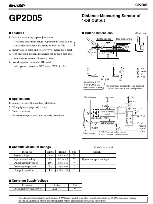
4.4to 7VCC (Ta=25˚C, V =5V)V CC -0.3to +10V V in-0.3to +3V BV O -0.3to +10V T opr-10to +60˚C T stg˚C(Unit : mm)FeaturesApplicationsAbsolute Maximum RatingsParameterSymbol Rating UnitRating Unit Operating Supply VoltageOutline DimensionsSupply voltageInput terminal voltage Output terminal voltage Operating temperature Storage temperatureGP2D05Distance Measuring Sensor of 1-bit OutputParameterRemarksOpen drain operation input1. Distance measuring type object sensorDistance measuring range : Optional distance can be set as threshold level by means of built-in VR2. Impervious to color and reflectivity of reflective object 1. Sanitary sensors (human body detection)2. OA equipment (paper detection)3. Game equipment4. For consumer products (human body detection)3. High precision distance measurement through output of continuous measurement average value ()-20to +704. Low dissipation current at OFF-state(dissipation current at OFF-state : TYP. 3µA)Operating supply voltage (Vcc)data books, etc. Contact SHARP in order to obtain the latest version of the device specification sheets before using any SHARP's device.”“In the absence of confirmation by device specification sheets, SHARP takes no responsibility for any defects that occur in equipment using any of SHARP's devices, shown in catalogs,s s s s s(Ta=25˚C,Vcc=5V)Electro-optical CharacteristicsSymbol MIN.TYP.MAX.Unit Distance measuring range 10-80cm Output terminal voltage V OH V CC -0.3--V V OL --0.3V --I CC -mA -38µA I vinVin =0V-µADistance characteristics of output Average dissipation current Dissipation current at OFF-state Iccoff Vo *1,*3Output voltage at Low, *1Output voltage at High, *1*1,*2*4*5cm 22-1601024L : Distance to reflective objectParameterConditionsVin terminal current-270*1 Reflective object : White paper (reflectivity : 90%)*2 Adjustment shall be available with the VR built in the sensor so that the output switching distance may be L=24 cm.*3 Distance measuring range on conditions after adjustment of the output switching distance to L=24*4 Average dissipation current measured on the conditions shown below*5 Dissipation current when Vin terminal is in High (current OFF) state.*6 Vin terminal : Open drain drive input.Conditions : Vin terminal current at Vin OFF-state >=2.6VVin terminal current at Vin ON-state <= 0.2VTiming Chart∆L Distance measuring operation starts sFig. 1 Distance Measuring Output vs. Distance to Reflective ObjectFig. 2 Detection Distance vs. Sensing RangeSensing range X (mm)D e t e c t i o n d i s t a n c e L (c m )D e t e c t i o n d i s t a n c e L (c m )Illuminance (lx)D i s t a n c e m e a s u r i n g o u t p u tTest Method for Sensing Range CharacteristicsTest Method for Anti External Disturbing Light CharacteristicsReflective object (reflectivity : 90%)Fig. 3 Detection Distance vs. IlluminanceSensing range X (cm)。
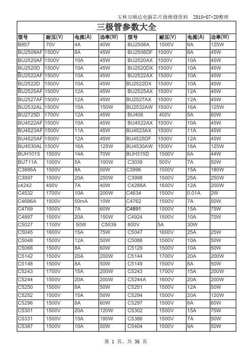
玉林万顺达电脑芯片级维修资料 2010-07-20整理玉林万顺达电脑芯片级维修资料 2010-07-20整理玉林万顺达电脑芯片级维修资料 2010-07-20整理玉林万顺达电脑芯片级维修资料 2010-07-20整理玉林万顺达电脑芯片级维修资料 2010-07-20整理玉林万顺达电脑芯片级维修资料 2010-07-20整理玉林万顺达电脑芯片级维修资料 2010-07-20整理玉林万顺达电脑芯片级维修资料 2010-07-20整理玉林万顺达电脑芯片级维修资料 2010-07-20整理玉林万顺达电脑芯片级维修资料 2010-07-20整理玉林万顺达电脑芯片级维修资料 2010-07-20整理玉林万顺达电脑芯片级维修资料 2010-07-20整理玉林万顺达电脑芯片级维修资料 2010-07-20整理玉林万顺达电脑芯片级维修资料 2010-07-20整理玉林万顺达电脑芯片级维修资料 2010-07-20整理玉林万顺达电脑芯片级维修资料 2010-07-20整理玉林万顺达电脑芯片级维修资料 2010-07-20整理玉林万顺达电脑芯片级维修资料 2010-07-20整理玉林万顺达电脑芯片级维修资料 2010-07-20整理玉林万顺达电脑芯片级维修资料 2010-07-20整理玉林万顺达电脑芯片级维修资料 2010-07-20整理玉林万顺达电脑芯片级维修资料 2010-07-20整理玉林万顺达电脑芯片级维修资料 2010-07-20整理玉林万顺达电脑芯片级维修资料 2010-07-20整理玉林万顺达电脑芯片级维修资料 2010-07-20整理玉林万顺达电脑芯片级维修资料 2010-07-20整理玉林万顺达电脑芯片级维修资料 2010-07-20整理玉林万顺达电脑芯片级维修资料 2010-07-20整理玉林万顺达电脑芯片级维修资料 2010-07-20整理玉林万顺达电脑芯片级维修资料 2010-07-20整理。
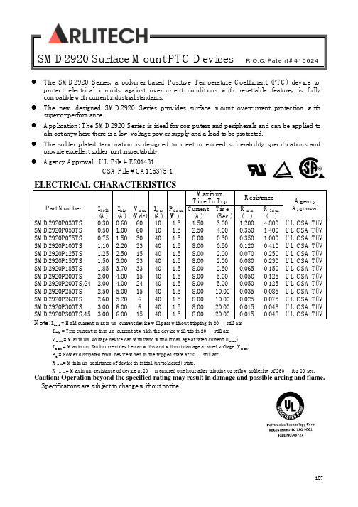
107SMD2920 Surface Mount PTC Devices R.O.C. Patent#415624ELECTRICAL CHARACTERISTICSMaximum Time To TripResistancePart NumberI hold (A)I trip (A) V max (Vdc) I max (A) P d max. (W) Current (A) Time (Sec.) R min (£[) R 1max (£[) Agency ApprovalSMD2920P030TS SMD2920P050TS SMD2920P075TS SMD2920P100TS SMD2920P125TS SMD2920P150TS SMD2920P185TS SMD2920P200TS SMD2920P200TS/24 SMD2920P250TS SMD2920P260TS SMD2920P300TS SMD2920P300TS/15 0.30 0.50 0.75 1.10 1.25 1.50 1.85 2.00 2.00 2.50 2.60 3.00 3.000.60 1.00 1.50 2.20 2.50 3.00 3.70 4.00 4.00 5.00 5.20 6.00 6.00 60 60 30 33 15 33 33 15 24 15 6 6 15 10 10 40 40 40 40 40 40 40 40 40 40 40 1.5 1.5 1.5 1.5 1.5 1.5 1.5 1.5 1.5 1.5 1.5 1.5 1.5 1.50 2.50 8.00 8.00 8.00 8.00 8.00 8.00 8.00 8.00 8.00 8.00 8.00 3.00 4.00 0.30 0.50 2.00 2.00 2.50 5.00 5.00 10.00 10.00 20.00 20.00 1.200 0.350 0.350 0.120 0.070 0.080 0.065 0.050 0.050 0.035 0.025 0.015 0.0154.800 1.400 1.000 0.410 0.250 0.230 0.150 0.125 0.125 0.085 0.075 0.048 0.048UL CSA TÜV UL CSA TÜV UL CSA TÜV UL CSA TÜV UL CSA TÜV UL CSA TÜV UL CSA TÜV UL CSA TÜV UL CSA TÜV UL CSA TÜV UL CSA TÜV UL CSA TÜV UL CSA TÜVNote: I hold = Hold current: maximum current device will pass without tripping in 20¢J still air.I trip = Trip current: minimum current at which the device will trip in 20¢J still air. V max = Maximum voltage device can withstand without damage at rated current (I max ) I max = Maximum fault current device can withstand without damage at rated voltage (V max ) P d = Power dissipated from device when in the tripped state at 20¢J still air. R min = Minimum resistance of device in initial (un-soldered) state.R 1max = Maximum resistance of device at 20¢J measured one hour after tripping or reflow soldering of 260¢J for 20 sec.Caution: Operation beyond the specified rating may result in damage and possible arcing and flame. ¡·Specifications are subject to change without notice.l The SMD2920 Series, a polymer-based Positive Temperature Coefficient (PTC) device to protect electrical circuits against overcurrent conditions with resettable feature, is fully compatible with current industrial standards. l The new designed SMD2920 Series provides surface mount overcurrent protection with superior performance.l Application: The SMD2920 Series is ideal for computers and peripherals and can be applied to almost anywhere there is a low voltage power supply and a load to be protected.lThe solder plated termination is designed to meet or exceed solderability specifications and provide excellent solder joint inspectability.l Agency Approval: UL File # E201431.CSA File # CA115375-1SMD2920 Surface Mount PTC Devices R.O.C. Patent#415624How to Select a Polymer PTC fuse:(1) Determine the following operating parameters for the circuits:(A) Normal Operating Current (I hold)(B) Maximum Circuit Voltage (V max)(C) Maximum Interrupt Current (I max)(D) Normal Operating Temperature (min¢J/max¢J)(2) Select the device form factor and dimension suitable for the application:Surface Mount Device (SMD Series)Radial Leaded Device (RLD Series)Axial Leaded Strap Device (STD Series)Other Custom-designed Device (Disc/Chip)(3) Compare the maximum ratings for V max and I max of the PTC device withthe circuit in application and make sure that the circuit’s requirement doesnot exceed the device ratings.(4) Check that the PTC device’s trip time (time-to-trip) will protect the circuit.(5) Verify that the circuit operating temperatures are within the PTC device’snormal operating temperature range.(6) Verify the performance and suitability of the chosen PTC device in theapplication.108109SMD2920 Surface Mount PTC Devices R.O.C. Patent#415624THERMAL DERATING CURVE FOR SMD2920 SERIESTHERMAL DERATING CHART FOR SMD2920 SERIES – Ihold (Amps)Ambient Operation TemperatureModel-40¢J -20¢J 0¢J 23¢J 40¢J 50¢J 60¢J 70¢J85¢J SMD2920P030TS 0.45 0.40 0.35 0.30 0.25 0.23 0.20 0.17 0.14 SMD2920P050TS 0.76 0.67 0.59 0.50 0.42 0.38 0.33 0.29 0.23 SMD2920P075TS 1.13 1.01 0.88 0.75 0.62 0.56 0.50 0.44 0.34 SMD2920P100TS 1.66 1.47 1.29 1.10 0.91 0.83 0.73 0.64 0.50 SMD2920P125TS 1.89 1.68 1.46 1.25 1.04 0.94 0.83 0.73 0.56 SMD2920P150TS 2.27 2.01 1.76 1.50 1.25 1.13 1.00 0.87 0.74 SMD2920P185TS 2.80 2.47 2.17 1.85 1.54 1.39 1.22 1.07 0.85 SMD2920P200TS 3.02 2.68 2.34 2.00 1.66 1.50 1.32 1.16 0.90 SMD2920P200TS/24 3.02 2.68 2.34 2.00 1.66 1.50 1.32 1.16 0.90 SMD2920P250TS 3.78 3.35 2.93 2.50 2.08 1.88 1.65 1.45 1.13 SMD2920P260TS 3.64 3.25 2.91 2.60 2.26 2.08 1.95 1.74 1.48 SMD2920P300TS 4.53 4.02 3.51 3.00 2.52 2.26 1.99 1.75 1.34 SMD2920P300TS/15 4.53 4.023.51 3.00 2.52 2.26 1.991.751.34-40.000.0040.0080.00120.00Device Ambient Temperature (¢J )0.0050.00100.00150.00200.00P e r c e n t a g e o f R a t e d C u r r e n t110SMD2920 Surface Mount PTC Devices R.O.C. Patent#415624AVERAGE TIME-CURRENT CURVE FOR SMD2920 SERIESSOLDER REFLOW0.10 1.0010.00100.00Fault Current (Amp.)0.010.101.0010.00100.00A BC D FG H J K E IT i m e t o T r i p (S e c .)A :SMD2920P030TSB :SMD2920P050TSC :SMD2920P075TSD :SMD2920P100TSE :SMD2920P150TSF :SMD2920P200TSG :SMD2920P125TSH :SMD2920P185TS I :SMD2920P250TSJ :SMD2920P260TSK :SMD2920P300TS111SMD2920 Surface Mount PTC Devices R.O.C. Patent#415624PHYSICAL DIMENSIONS (mm)A B C D E Part Number Min. Max. Min. Max. Min. Max. Min. Min. Max. SMD2920P030TS 6.73 7.98 4.80 5.44 0.75 1.25 0.30 0.25 2.00 SMD2920P050TS 6.73 7.98 4.80 5.44 0.75 1.25 0.30 0.25 2.00 SMD2920P075TS 6.73 7.98 4.80 5.44 0.75 1.25 0.30 0.25 2.00 SMD2920P100TS 6.73 7.98 4.80 5.44 0.55 1.00 0.30 0.25 2.00 SMD2920P125TS 6.73 7.98 4.80 5.44 0.55 1.00 0.30 0.25 2.00 SMD2920P150TS 6.73 7.98 4.80 5.44 0.75 1.25 0.30 0.25 2.00 SMD2920P185TS 6.73 7.98 4.80 5.44 0.75 1.25 0.30 0.25 2.00 SMD2920P200TS 6.73 7.98 4.80 5.44 0.75 1.25 0.30 0.25 2.00 SMD2920P250TS 6.73 7.98 4.80 5.44 0.75 1.25 0.30 0.25 2.00 SMD2920P260TS 6.73 7.98 4.80 5.44 0.55 1.00 0.30 0.25 2.00 SMD2920P300TS 6.73 7.98 4.80 5.44 0.75 1.25 0.30 0.25 2.00 SMD2920P300TS/156.737.984.805.440.751.250.300.252.00ENVIRONMENTAL SPECIFICATIONSOperating/Storage Temperature-40¢J to +85¢J Maximum Device Surface Temperature in Tripped State 125¢JPassive Aging +85¢J, 1000 hours ±5% typical resistance change Humidity Aging +85¢J, 85%R.H. 1000 hours ±5% typical resistance change Thermal Shock MIL-STD-202 Method 107G+85¢J/-40¢J 20 times -30% typical resistance change Solvent Resistance MIL-STD-202, Method 215 No changeVibrationMIL-STD-883C, Method 2007.1, Condition A No changePHYSICAL SPECIFICATIONSTerminal Material Solder-Plated Copper (Solder Material: 63/37 SnPb)Lead Solderability Meets EIA Specification RS186-9E, ANSI/J-STD-002 Category 3. Packaging16 mm tape on 7 inch reel per EIA-481-1 (equivalent to IEC286, part 3) 2000 devices per reel for P100TS, P125TS &P260 others : 1500 devices per reel¡· Specifications are subject to change without notice.FIGURESOLDER PAD LAYOUTSSMD2920 Surface Mount PTC Devices R.O.C. Patent#415624TAPE SPECIFICATIONS: EIA-481-1P030TS-P075TS P100TS P150TS–P185TSP050TS P125TS P200TS–P250TSP260TS P300TSW 16.0+/-0.30 16.0+/-0.30 16.0+/-0.307.5+/-0.05 7.5+/-0.05 7.5+/-0.051 1.75+/-0.10 1.75+/-0.10 1.75+/-0.100 1.55+/-0.05 1.55+/-0.05 1.55+/-0.051 1.5+/-0.10 1.5+/-0.10 1.5+/-0.10P0 4.0+/-0.10 4.0+/-0.10 4.0+/-0.101 8.0+/-0.10 8.0+/-0.10 8.0+/-0.10P2 2.0+/-0.05 2.0+/-0.05 2.0+/-0.050 5.45+/-0.10 5.45+/-0.10 5.45+/-0.1007.65+/-0.10 7.65+/-0.10 7.65+/-0.10T 0.25+/-0.10 0.25+/-0.10 0.25+/-0.100 1.25+/-0.10 1.00+/-0.10 1.45+/-0.10Leader min. 390 390 390160 160 160(mm)H 12.0+/-0.15W 9.0+/-0.5D 60+/−0.5F 13.0+/-0.2C 178+/-1.0H111+/-0.5W1 2.5+/-0.5W2 3.0+/-0.5W3 4.0+/-0.5W4 5.0+/-0.5(mm)112SMD2920 Surface Mount PTC Devices R.O.C. Patent#415624 PART NUMBERING SYSTEMSMD2920 P ¡¼¡¼¡¼TSSolder Plated TerminationMultilayer Thickness VersionCurrent RatingPolytronics SymbolDevice Dimensions: Length/Width(Unit: 1/100 inch)Surface Mount DeviceCROSS REFERENCECross ReferencePolytronics/ EVERFUSE TMRaychem/ PolySwitch® Bourns/ Multifuse®SMD2920P030TS SMD2920P050TS SMD2920P075TS SMD2920P100TS SMD2920P125TSSMD2920P150TS SMD2920P185TS SMD2920P200TSSMD2920P200TS/24 SMD2920P250TS SMD2920P260TS SMD2920P300TSSMD2920P300TS/15 SMD030SMD050SMD075SMD100/33SMD125SMD150/33 (3425)SMD185 (3425)SMD200 (3425)N/ASMD250 (3425)SMD260SMD300N/AMF-SM030MF-SM050(30Vdc)MF-SM075MF-SM100(30Vdc)MF-SM125MF-SM150(15Vdc)N/AMF-SM200 (3425)N/AMF-SM250 (3425)MF-SM260N/AN/A“Multifuse” is a registered trademark of Bourns , Inc.“PolySwitch” is a registered trademark of Raychem Corporation.¡· S pecifications are subject to change without notice.113SMD2920 Surface Mount PTC Devices R.O.C. Patent#415624 114。
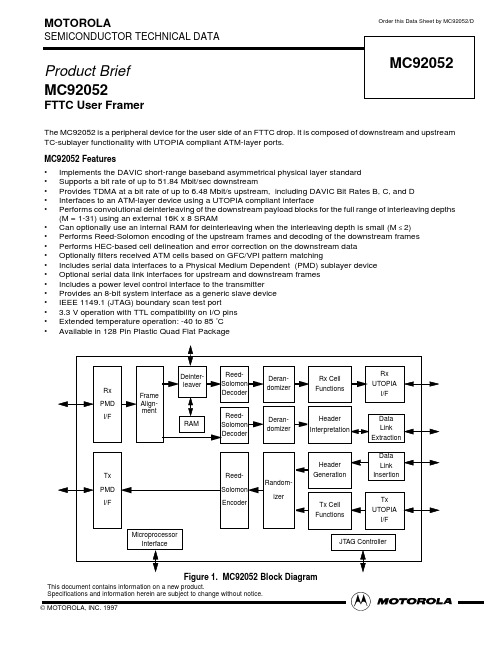
MOTOROLASEMICONDUCTOR TECHNICAL DATAOrder this Data Sheet by MC92052/DProduct Brief MC92052FTTC User FramerThe MC92052 is a peripheral device for the user side of an FTTC drop. It is composed of downstream and upstream TC-sublayer functionality with UTOPIA compliant ATM-layer ports.MC92052 Features •Implements the DAVIC short-range baseband asymmetrical physical layer standard •Supports a bit rate of up to 51.84 Mbit/sec downstream•Provides TDMA at a bit rate of up to 6.48 Mbit/s upstream, including DAVIC Bit Rates B, C, and D •Interfaces to an ATM-layer device using a UTOPIA compliant interface•Performs convolutional deinterleaving of the downstream payload blocks for the full range of interleaving depths (M = 1-31) using an external 16K x 8 SRAM•Can optionally use an internal RAM for deinterleaving when the interleaving depth is small (M ≤2)•Performs Reed-Solomon encoding of the upstream frames and decoding of the downstream frames •Performs HEC-based cell delineation and error correction on the downstream data •Optionally filters received ATM cells based on GFC/VPI pattern matching•Includes serial data interfaces to a Physical Medium Dependent (PMD) sublayer device •Optional serial data link interfaces for upstream and downstream frames •Includes a power level control interface to the transmitter •Provides an 8-bit system interface as a generic slave device •IEEE 1149.1 (JTAG) boundary scan test port • 3.3 V operation with TTL compatibility on I/O pins •Extended temperature operation: -40 to 85°C •Available in 128 Pin Plastic Quad Flat PackageFigure 1.MC92052 Block DiagramFrame Deinter-JTAG ControllerleaverDeran-domizer Rx PMD I/FReed-Solomon EncoderRandom-izerTx PMD I/FReed-Solomon Decoder Rx Cell FunctionsRx UTOPIA I/F Align-mentData Link Extraction Reed-Solomon DecoderDeran-domizer Tx UTOPIA I/FHeader InterpretationHeader GenerationTx Cell FunctionsData Link Insertion RAMMicroprocessor InterfaceMC92052This document contains information on a new product.Specifications and information herein are subject to change without notice.元器件交易网General DescriptionThe MC92052 implements the TC sublayer of the DAV-IC asymmetrical FTTC PHY specification for user devic-es. The MC92052 key functional blocks are described in the paragraphs which follow.Rx PMD InterfaceThe receive PMD interface receives a clock signal and a serial data stream. The clock is used both to sample the data and to clock the operation of the MC92052. Frame AlignmentWhen in the “out-of-frame” condition, the frame align-ment block searches the serial data (which is LSB first) for the 16-bit framing pattern and then converts it to 8-bit parallel data aligned to the framing pattern. When in the “in-frame” condition, the serial-to-parallel block ver-ifies the framing pattern and continues to convert it to parallel data using the current alignment. In each frame, the two framing bytes are discarded, the next 16 bytes are provided to the header flow, and the following (12 * 66) bytes are provided to the payload flow. DeinterleaverThe deinterleaver block recovers the original data blocks from the interleaved data that it receives. Trans-mitting interleaved data allows for better correction of bursts of errors because the deinterleaver spreads the incorrect data over many blocks so that the Reed-So-lomon decoder can correct the small number of errors in each block.The deinterleaver separates the data byte stream into 33 branches. Each of the branches is delayed by a dif-ferent amount, and then they are recombined into a sin-gle data stream. The delay of branch k (0≤ k≤ 32) is M * (32 - k). M is the Interleaving Depth Parameter re-covered from the frame header and ranges from 0 to 31. M=0 effectively disables the deinterleaver.The delay of the interleaver/deinterleaver combination is 1056 * M payload byte periods. The deinterleaver is implemented using an external SRAM (MotorolaMCM6306 or equivalent). Alternatively, the internal RAM can be used if the value of M is 1 or 2.Reed-Solomon DecodersOne Reed-Solomon decoder is used for the header. It decodes the (16,12) code in order to correct up to 2 bytes or declare the header to be uncorrectable.The other decoder is used for the payload blocks. It de-codes the (66,58) codes in order to correct up to 4 bytes or declare the block to be uncorrectable, in which case the data is not touched.DerandomizersThe received data has been randomized on the network side for better transmission performance. The deran-domizers perform the inverse function to restore the original data.The two derandomizers are identical. One is used for the 12 header bytes per frame, and the other is used for the 12*58 payload bytes per frame. The derandomizers are self-synchronizing since they depend only on the previously received data.Frame Header Interpretation BlockThe header interpretation block extracts the useful in-formation from the received frame header. It provides information to the transmit flow regarding when to transmit a cell, etc.Data Link ExtractionThe data link extraction block optionally provides the data link bytes of the downstream frame headers to a serial data link controller (e.g., MC68360 QUICC) for further processing. The received downstream data link bytes are extracted using a clock pin and a data pin. Rx Cell FunctionsThe receive cell functions block recovers 53-octet ATM cells from the derandomized byte stream using the HEC-based method described in ITU-T Recommenda-tion I.432.Once the cell alignment has been recovered, the re-ceive cell functions block checks the received HEC val-ue against the calculated value and corrects single-bit errors in the header. Any cell with non-correctable er-rors is discarded. Then the cells are filtered based on the header value. Idle cells are discarded. Additional cells may be discarded as a result of the GFC/VPI pat-tern matching option.The cell functions block also derandomizes the payload of the ATM cells to recover the original data and trans-fers entire ATM cells to the receive cell FIFO.Counts of the cells transferred to the receive cell FIFO and the cells that are discarded due to header errors are maintained.Rx UTOPIA InterfaceThe receive UTOPIA interface reads the ATM cells from the receive cell FIFO and transfers them to the ATM lay-er according to the ATM Forum UTOPIA Level 1 speci-fication. This block uses RXCLK provided by the ATM layer. The FIFO is used for rate adaptation between RX-CLK (the UTOPIA interface clock) and the device clock. Tx UTOPIA InterfaceThe Transmit UTOPIA interface accepts ATM cells from the ATM layer according to the UTOPIA specification. The cells are stored in the transmit cell FIFO. This block uses TXCLK provided by the ATM layer. The FIFO is used for rate adaptation between TXCLK (the UTOPIA interface clock) and the device clock.Tx Cell FunctionsThe transmit cell functions block reads ATM cells from the transmit cell FIFO. If there are no cells available when an upstream frame should be transmitted, the cell functions block generates an idle cell. It calculates the HEC value based on the ATM header of each cell and inserts it in the fifth octet of the cell.A count of the cells transferred from the transmit cell FIFO is maintained.Data Link InsertionThe data link insertion block provides direct serial ac-cess to the data link bytes of the upstream frame head-ers. The data link stream for the upstream frames is optionally inserted using an output clock pin and an in-put data pin.Frame Header GenerationThe frame header generation block generates the six header bytes for each upstream frame. RandomizerThe randomizer operates on 4 header bytes and 53 ATM cell bytes of each upstream frame. It is initialized to all ones at the beginning of each frame. The 2 SYNC bytes are not randomized.Reed-Solomon EncoderThe Reed-Solomon encoder operates on 57 bytes of the upstream frame and adds 8 parity bytes to produce a (65,57) RS code.Tx PMD InterfaceThe transmit PMD interface block transfers bursts of se-rial data. The control signals of this interface include a transmit enable signal and a clock signal that is gener-ated internally by dividing down the clock provided at the receive PMD interface.Microprocessor InterfaceThe microprocessor interface is an 8-bit generic slave interface. It is used for initializing the internal registers and reading status registers and counters.JTAGThe MC92052 provides JTAG boundary scan.System Functional Description Downstream Data FlowIn the downstream direction, the MC92052 receives the data and clock recovered by the PMD device. The frame alignment is recovered by searching for the SYNC bytes. Once the frame alignment is known, the header and payload are split into separate processing paths. The header undergoes error correction by a Reed-Solomon decoder. It is then derandomized and processed in accordance with the definition of the head-er bytes.The payload passes through a convolutional deinter-leaver and is then divided into blocks of 66 bytes. Each block undergoes error correction by a Reed-Solomon decoder. The corrected payload data is then derandom-ized. The resulting data stream is delineated into ATM cells using the HEC-based delineation method ofITU-T Recommendation I.432. Any physical layer cells are discarded, and the remaining cells are transferred to the ATM layer using a UTOPIA compliant interface. Upstream Data FlowIn the upstream direction, the MC92052 implements TDMA, including sign-on, as directed by the network de-vice using the frame overhead of the downstream frames. If no cell is available from the ATM layer, an idle cell is generated. The frame overhead is added to the ATM cell, and then the 57-byte frame is randomized. A Reed-Solomon encoder adds eight parity bytes. The entire frame is transferred to the PMD device along with an enable signal to provide the proper timing with re-spect to the downstream superframe.Other FunctionsA microprocessor interface is provided for configura-tion, control, and status monitoring.A standard IEEE 1149.1 boundary scan test port is pro-vided.ApplicationsThe primary application of the MC92052 is to provide TC-sublayer processing functions for a user device,e.g., a set-top box, in an FTTC network. Figure 2 shows the location of the user device within an FTTC networkusing a passive network termination. Figure 3 shows a generic user device architecture using the MC92052.The MC92052 uses an external memory for convolu-tional interleaving of the downstream data. If the inter-leaving depth is very small or if interleaving is not used,the external memory is not required.Figure 2. Typical FTTC NetworkAccess Networkoptical fiberONUcoax / copper pairPassive SplitterNetwork DeviceUser Device(Set-T op Box /Adaptor Card / etc.)Passive SplitterMC92052User Device(Set-T op Box /Adaptor Card / etc.)MC92052User Device(Set-T op Box /Adaptor Card / etc.)MC92052User Device(Set-T op Box /Adaptor Card / etc.)MC92052MC92053Network DeviceMC92053Figure 3. Generic User DeviceTable 1.MC92052 Package/Frequency AvailabilityUser Devicecoax / copper pairApplication Processor(MPEG decoder)MC92052UTOPIAµPSARMCM6206PMDSRAMMCM6306or Package Type Frequency (MHz)Temperature Order Number 128-pin PQFP0 - 52-40˚ to 85˚ CMC92052CG。
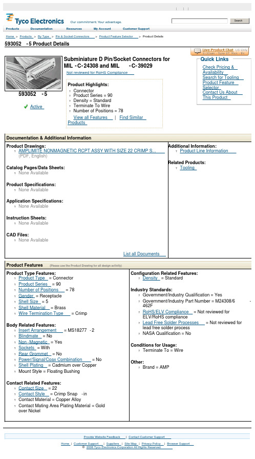
593052-5 Product DetailsHome | Customer Support | Suppliers | Site Map | Privacy Policy | Browser Support© 2008 Tyco Electronics Corporation All Rights Reserved SearchProducts Documentation Resources My Account Customer SupportHome > Products > By Type > Pin & Socket Connectors > Product Feature Selector > Product Details593052-5Active Subminiature D Pin/Socket Connectors forMIL-C-24308 and MIL-C-39029Not reviewed for RoHS ComplianceProduct Highlights:?Connector?Product Series = 90?Density = Standard?Terminate To Wire?Number of Positions = 78View all Features | Find SimilarProductsCheck Pricing &AvailabilitySearch for ToolingProduct FeatureSelectorContact Us AboutThis ProductQuick LinksDocumentation & Additional InformationProduct Drawings:?AMPLIMITE NONMAGNETIC RCPT ASSY WITH SIZE 22 CRIMP S...(PDF, English)Catalog Pages/Data Sheets:?None AvailableProduct Specifications:?None AvailableApplication Specifications:?None AvailableInstruction Sheets:?None AvailableCAD Files:?None AvailableList all Documents Additional Information:?Product Line InformationRelated Products:?ToolingProduct Features (Please use the Product Drawing for all design activity)Product Type Features:?Product Type = Connector?Product Series = 90?Number of Positions = 78?Gender = Receptacle?Shell Size = 5?Shell Material = Brass?Wire Termination Type = CrimpBody Related Features:?Insert Arrangement = MS18277-2?Blindmate = No?Non-Magnetic = Yes?Sockets = With?Rear Grommet = No?Power/Signal/Coax Combination = No?Shell Plating = Cadmium over Copper?Mount Style = Floating BushingContact Related Features:?Contact Size = 22?Contact Style = Crimp Snap-in?Contact Material = Copper Alloy?Contact Mating Area Plating Material = Goldover Nickel Configuration Related Features:?Density = StandardIndustry Standards:?Government/Industry Qualification = Yes?Government/Industry Part Number = M24308/6-462F?RoHS/ELV Compliance = Not reviewed forELV/RoHS compliance?Lead Free Solder Processes = Not reviewed forlead free solder process?NASA Qualification = NoConditions for Usage:?Terminate To = WireOther:?Brand = AMPProvide Website Feedback | Contact Customer Support。

Dell™ Latitude™ D530Quick Reference GuideModel PP17Lw w w.d e l l.c o m|s u p p o r t.d e l l.c o mNotes, Notices, and CautionsNOTE: A NOTE indicates important information that helps you make better use of your computer.NOTICE: A NOTICE indicates either potential damage to hardware or loss of data and tells you how to avoid the problem.CAUTION: A CAUTION indicates a potential for property damage, personal injury, or death.____________________Information in this document is subject to change without notice.©2007Dell Inc.All rights reserved.Reproduction in any manner whatsoever without the written permission of Dell Inc. is strictly forbidden.Trademarks used in this text: Dell, the DELL logo, Latitude, ExpressCharge, and Undock & Go are trademarks of Dell Inc.; Microsoft, Windows, Outlook, and Windows Vista are either trademarks or registered trademarks of Microsoft Corporation in the United States and/or other countries; Bluetooth is a registered trademark owned by Bluetooth SIG, Inc. and is used by Dell under license.Other trademarks and trade names may be used in this document to refer to either the entities claiming the marks and names or their products. Dell Inc. disclaims any proprietary interest in trademarks and trade names other than its own.Model PP17LSeptember 2007P/N NM070Rev. A00ContentsFinding Information (5)Setting Up Your Computer (11)Transferring Information to a NewComputer (11)Turning Off Your Computer (16)About Your Computer (17)Front View (17)Left Side View (18)Right Side View (18)Back View (19)Bottom View (20)Using a Battery (21)Battery Performance (21)Checking the Battery Charge (22)Power Management Modes (24)Configuring Power Management Settings (26)Accessing Power Options Properties (26)Charging the Battery (26)Replacing the Battery (27)Storing a Battery (28)Troubleshooting (28)Lockups and Software Problems (29)Dell Diagnostics (30)Index (35)Contents34ContentsQuick Reference Guide 5Finding InformationNOTE: Some features or media may be optional and may not ship with your computer. Some features or media may not be available in certain countries.NOTE:Additional information may ship with your computer.What Are You Looking For?Find It Here•A diagnostic program for my computer •Drivers for my computer •My device documentation •Notebook System Software (NSS)Drivers and Utilities DiscDocumentation and drivers are already installed on your computer. Y ou can use the disc to reinstall drivers (see"Reinstalling Drivers and Utilities" in your User’s Guide ) or to run the Dell Diagnostics (see "Starting the Dell Diagnostics From the Optional Drivers and Utilities Disc" on page 32).Readme files may be included on your disc to provide last-minute updates about technical changes to your computer or advanced technical-reference material for technicians or experienced users.NOTE: Drivers and documentationupdates can be found at .NOTE: The Drivers and Utilities disc maybe optional and may not ship with your computer.•Warranty information•Terms and Conditions (U.S. only)•Safety instructions•Regulatory information•Ergonomics information•End User License AgreementDell™ Product Information Guide•Specifications•How to configure system settings •How to troubleshoot and solve problems Dell Latitude™ User’s GuideMicrosoft® Windows® XP and Windows Vista™ Help and Support Center1Click Start→Help and Support→Dell User and System Guides→System Guides.2Click the User’s Guide for yourcomputer.What Are You Looking For?Find It Here6Quick Reference Guide•Service Tag and Express Service Code •Microsoft Windows License Label Service Tag and Microsoft® Windows®LicenseNOTE: Your computer’s Service Tag and Microsoft Windows License labels are located on your computer.Y our computer’s Service Tag contains both a Service Tag number and an Express Service Code.•Use the Service Tag to identify yourcomputer when you use or contact support. •Enter the Express Service Code todirect your call when contactingsupport.•Use the product key on the LicenseLabel if you need to reinstall youroperating system.NOTE: As an increased security measure, the newly designed Microsoft Windows license label incorporates a missing portion or "hole" to discourage removal of the label.What Are You Looking For?Find It HereQuick Reference Guide7•Solutions — Troubleshooting hints and tips, articles from technicians, and online courses, frequently asked questions•Community — Online discussion with other Dell customers•Upgrades — Upgrade information for components, such as memory, the hard drive, and the operating system •Customer Care — Contact information, service call and order status, warranty, and repair information•Service and support — Service call status and support history, service contract, online discussions with technical support•Dell Technical Update Service — Proactive e-mail notification of software and hardware updates for your computer•Reference — Computer documentation, details on my computer configuration, product specifications, and white papers •Downloads — Certified drivers, patches, and software updates Dell Support Website — NOTE: Select your region or businesssegment to view the appropriate support site.What Are You Looking For?Find It Here8Quick Reference Guide•Notebook System Software (NSS) — If you reinstall the operating system for your computer, you should also reinstall the NSS utility. NSS provides critical updates for your operating system and support for processors, optical drives, USB devices, and so on. NSS is necessary for correct operation of your Dell computer. The software automatically detects your computer and operating system and installs the updates appropriate for your configuration.To download Notebook System Software:1Go to and click Drivers & Downloads.2Enter your Service Tag and click Go,or select your Product T ype and Product Model and click Confirm.3Click the plus sign (+) by System Utilities, click Notebook System Software, and click Download Now.4Click Run to run the utility. NOTE: The user interface may vary depending on your selections.•Software upgrades and troubleshooting hints — Frequently asked questions, hot topics, and general health of your computing environment Dell Support UtilityThe Dell Support Utility is an automated upgrade and notification system installed on your computer. This support provides real-time health scans of your computing environment, software updates, and relevant self-support information. Access the Dell Support Utility from the icon in the taskbar.•How to find information about my computer and its components •How to connect to the Internet •How to add user accounts for different people•How to transfer files and settings from another computer Windows Welcome CenterThe Windows Welcome Centerautomatically appears when you use thecomputer for the first tme. Y ou canchoose to have it appear every time youstart your PC by placing a check in the Run at startup checkbox. Another method of accessing the WelcomeCenter is to click the Windows VistaStart button , and then click Welcome Center.What Are You Looking For?Find It HereQuick Reference Guide9•How to use Microsoft Windows XP •How to use Microsoft Windows Vista •How to work with programs and files •How to personalize my desktop Windows Help and SupportMicrosoft Windows XP:1Click the Start button and click Help and Support.2Either select one of the topics listed, or type a word or phrase that describesyour problem into the Search box,click the arrow icon, and then click the topic that describes your problem.3Follow the instructions on the screen. Microsoft Windows Vista:1Click the Windows Vista Start button , and then click Help and Support. 2In Search Help, type a word or phrase that describes your problem, and then press <Enter> or click the magnifying glass.3Click the topic that describes yourproblem.4Follow the instructions on the screen.•Information on network activity, the Power Management Wizard, hotkeys, and other items controlled by Dell QuickSet.Dell QuickSet HelpTo view Dell QuickSet Help, right-click the QuickSet icon in the Microsoft Windows taskbar, and select Help. The taskbar is located in the lower-right corner of your screen.•How to reinstall my operating system Operating System DiscNOTE: The Operating System disc may beoptional and may not ship with yourcomputer.NOTE: Pre-installed operating systemsinclude a recover partition to restore yourPC operating system.What Are You Looking For?Find It Here10Quick Reference GuideSetting Up Your ComputerTransferring Information to a New ComputerY ou can use your operating system "wizards" to help you transfer files and other data from one computer to another—for example, from an oldcomputer to a new computer. For instructions, see the following section that corresponds to the operating system that your computer is running.The operating system is already installed on your computer. To reinstall your operating system, use the Operating System disc.After you reinstall your operatingsystem, use the Drivers and Utilities disc to reinstall drivers for the devices that came with your computer.Y our operating system product key label is located on your computer.NOTE: The color of your disc variesbased on the operating system you ordered.What Are You Looking For?Find It HereMicrosoft Windows XPThe Microsoft Windows XP operating system provides the Files and Settings Transfer Wizard to move data from a source computer to a new computer. Y ou can transfer data, such as:•E-mail messages•Toolbar settings•Window sizes•Internet bookmarksY ou can transfer the data to the new computer over a network or serial connection, or you can store it on removable media, such as a writable CD, for transfer to the new computer.NOTE: You can transfer information from an old computer to a new computer by directly connecting a serial cable to the input/output (I/O) ports of the twocomputers. To transfer data over a serial connection, you must access the Network Connections utility from the Control Panel and perform additional configurationsteps, such as setting up an advanced connection and designating the hostcomputer and the guest computer.For instructions on setting up a direct cable connection between two computers, see Microsoft Knowledge Base Article #305621, titled How to Set Up a Direct Cable Connection Between Two Computers in Windows XP. This information may not be available in certain countries.For transferring information to a new computer, you must run the Files and Settings Transfer Wizard. Y ou can use the optional Operating System disc for this process or you can create a wizard disk with the Files and Settings Transfer Wizard.Running the Files and Settings Transfer Wizard With the Operating System DiscNOTE: This procedure requires the Operating System disc. This disc is optional and may not be included with certain computers.To prepare a new computer for the file transfer:1Open the Files and Settings Transfer Wizard: click Start→All Programs→Accessories→ System Tools→Files and Settings Transfer Wizard.2When the Files and Settings Transfer Wizard welcome screen appears, click Next.3On the Which computer is this? screen, click New Computer→Next.4On the Do you have a Windows XP CD? screen, click I will use the wizard from the Windows XP CD→Next.5When the Now go to your old computer screen appears, go to your old or source computer. Do not click Next at this time.To copy data from the old computer:1On the old computer, insert the Windows XP Operating System disc.2On the Welcome to Microsoft Windows XP screen, click Perform additional tasks.3Under What do you want to do?, click Transfer files and settings→ Next. 4On the Which computer is this? screen, click Old Computer→Next.5On the Select a transfer method screen, click the transfer method you prefer.6On the What do you want to transfer? screen, select the items you want to transfer and click Next.After the information has been copied, the Completing the Collection Phase screen appears.7Click Finish.To transfer data to the new computer:1On the Now go to your old computer screen on the new computer, click Next.2On the Where are the files and settings? screen, select the method you chose for transferring your settings and files and click Next.The wizard reads the collected files and settings and applies them to your new computer.When all of the settings and files have been applied, the Finished screen appears.3Click Finished and restart the new computer.Running the Files and Settings Transfer Wizard Without the Operating System DiscTo run the Files and Settings Transfer Wizard without the Operating System disc, you must create a wizard disc that will allow you to create a backup image file to removable media.To create a wizard disk, use your new computer with Windows XP and perform the following steps:1Open the Files and Settings Transfer Wizard: click Start→All Programs→Accessories→ System Tools→Files and Settings Transfer Wizard.2When the Files and Settings Transfer Wizard welcome screen appears, click Next.3On the Which computer is this? screen, click New Computer→Next.4On the Do you have a Windows XP CD? screen, click I want to create a Wizard Disk in the following drive→ Next.5Insert the removable media, such as a writable CD, and click OK.6When the disk creation completes and the Now go to your old computer message appears, do not click Next.7Go to the old computer.To copy data from the old computer:1On the old computer, insert the wizard disk.2Click Start→Run.3In the Open field on the Run window, browse to the path for fastwiz (on the appropriate removable media) and click OK.4On the Files and Settings Transfer Wizard welcome screen, click Next.5On the Which computer is this? screen, click Old Computer→Next.6On the Select a transfer method screen, click the transfer method you prefer.7On the What do you want to transfer? screen, select the items you want to transfer and click Next.After the information has been copied, the Completing the Collection Phase screen appears.8Click Finish.To transfer data to the new computer:1On the Now go to your old computer screen on the new computer, click Next.2On the Where are the files and settings? screen, select the method you chose for transferring your settings and files and click Next. Follow theinstructions on the screen.The wizard reads the collected files and settings and applies them to your new computer.When all of the settings and files have been applied, the Finished screen appears.3Click Finished and restart the new computer.NOTE: For more information about this procedure, search fordocument #154781 (What Are The Different Methods To Transfer Files From My Old Computer To My New Dell™ Computer Using the Microsoft® Windows® XPOperating System?).NOTE: Access to the Dell Knowledge Base document may not be available incertain countries.Microsoft Windows Vista1Click the Windows Vista Start button , and then click Transfer files and settings→Start Windows Easy Transfer.2In the User Account Control dialog box, click Continue.3Click Start a new transfer or Continue a transfer in progress.Follow the instructions provided on the screen by the Windows Easy Transfer wizard.Turning Off Your ComputerNOTICE: To avoid losing data, save and close all open files and exit all openprograms before you turn off your computer.1Shut down the operating system:a Save and close all open files and exit all open programs.b In the Microsoft Windows XP operating system, click Start→ShutDown→Shut down.In the Microsoft Windows Vista™ operating system, click the WindowsVista Start button , click the arrow in the lower-right corner of theStart menu as shown below, and then click Shut Down.The computer turns off after the operating system shutdown processis complete.2Ensure that the computer and all attached devices are turned off. If your computer and attached devices did not automatically turn off when you shut down your operating system, press and hold the power button forabout 4 seconds to turn them off.About Your ComputerFront View1display 2device status lights 3keyboard 4touch pad 5display latch 6speaker7touch pad buttons 8keyboard status lights9power button413872695Left Side ViewRight Side View1security cable slot 2IEEE 1394 Connector 3PC Card/ExpressCard slot 4infrared sensor 5audio connectors (2)6hard drive1media bay 2device latch release3USB connectors (2)352416123Back View1USB connectors (2)2modem connector (RJ-11)3network connector (RJ-45)4S-video TV-out connector 5serial connector 6video connector 7AC adapter connector8air vents81234567Bottom View1memory module/modem/WLAN Mini-Card/coin-cell battery cover2battery-bay latch release3battery charge gauge/health gauge4battery 5docking-device connector 6air vents7hard drive1542736Using a BatteryBattery PerformanceNOTE: For information about the Dell warranty for your computer, see the Product Information Guide or separate paper warranty document that shipped with yourcomputer.For optimal computer performance and to help preserve BIOS settings, operate your Dell portable computer with the main battery installed at all times. One battery is supplied as standard equipment in the battery bay.NOTE: Because the battery may not be fully charged, use the AC adapter toconnect your new computer to an electrical outlet the first time you use thecomputer. For best results, operate the computer with the AC adapter until thebattery is fully charged. To view battery charge status, check the Power Meter in Power Options (see "Accessing Power Options Properties" on page26).NOTE: Battery operating time (the time the battery can hold a charge) decreases over time. Depending on how often the battery is used and the conditions underwhich it is used, you may need to purchase a new battery during the life of yourcomputer.NOTE: It is recommended that you connect your computer to an electrical outlet when writing to a CD or DVD.Operating time is significantly reduced when you perform operations including, but not limited to, the following:•Using optical drives.•Using wireless communications devices, PC Cards, Express Cards, media memory cards, or USB devices.•Using high-brightness display settings, 3D screen savers, or other power-intensive programs such as complex 3D graphics applications.•Running the computer in maximum performance mode. See "Configuring Power Management Settings" on page26 for information about accessing Windows Power Options Properties or Dell QuickSet, which you can use to configure power management settings.Y ou can check the battery charge before you insert the battery into the computer. Y ou can also set power management options to alert you when the battery charge is low.CAUTION: Using an incompatible battery may increase the risk of fire orexplosion. Replace the battery only with a compatible battery purchased fromDell. The battery is designed to work with your Dell computer. Do not use a battery from other computers with your computer.CAUTION: Do not dispose of batteries with household waste. When your battery no longer holds a charge, call your local waste disposal or environmental agency for advice on disposing of a lithium-ion battery. See "Battery Disposal" in theProduct Information Guide.CAUTION: Misuse of the battery may increase the risk of fire or chemical burn.Do not puncture, incinerate, disassemble, or expose the battery to temperatures above 65°C (149°F). Keep the battery away from children. Handle damaged orleaking batteries with extreme care. Damaged batteries may leak and causepersonal injury or equipment damage.Checking the Battery ChargeThe Dell QuickSet Battery Meter, the Microsoft Windows Power Meter window and icon, the battery charge gauge and health gauge, and the low-battery warning provide information on the battery charge.Dell QuickSet Battery MeterIf Dell QuickSet is installed, press <Fn><F3> to display the QuickSet Battery Meter. The Battery Meter displays status, battery health, charge level, and charge completion time for the battery in your computer.For more information about QuickSet, right-click the QuickSet icon in the taskbar, and click Help.Microsoft Windows Power MeterThe Windows Power Meter indicates the remaining battery charge. To check the Power Meter, double-click the icon on the taskbar.If the computer is connected to an electrical outlet, a icon appears.Charge GaugeBy either pressing once or pressing and holding the status button on the charge gauge on the battery, you can check:•Battery charge (check by pressing and releasing the status button)•Battery health (check by pressing and holding the status button)The battery operating time is largely determined by the number of times it is charged. After hundreds of charge and discharge cycles, batteries lose some charge capacity—or battery health. That is, a battery can show a status of "charged" but maintain a reduced charge capacity (health).Check the Battery ChargeTo check the battery charge, press and release the status button on the battery charge gauge to illuminate the charge-level lights. Each light represents approximately 20 percent of the total battery charge. For example, if the battery has 80 percent of its charge remaining, four of the lights are on. If no lights appear, the battery has no charge.Check the Battery HealthNOTE: You can check battery health in one of two ways: by using the charge gauge on the battery as described below and by using the Battery Meter in Dell QuickSet.For information about QuickSet, right-click the icon in the taskbar, and click Help. To check the battery health using the charge gauge, press and hold the status button on the battery charge gauge for at least 3seconds. If no lights appear, the battery is in good condition, and more than 80 percent of its original charge capacity remains. Each light represents incremental degradation. If five lights appear, less than 60percent of the charge capacity remains, and you should consider replacing the battery. See "Using a Battery" on page21 for more information about the battery operating time.Low-Battery WarningNOTICE: To avoid losing or corrupting data, save your work immediately after alow-battery warning. Then connect the computer to an electrical outlet, or install a second battery in the media bay. If the battery runs completely out of power,hibernate mode begins automatically.A pop-up window warns you when the battery charge is approximately90percent depleted. If two batteries are installed, the low-battery warning means that the combined charge of both batteries is approximately90percent depleted. The computer enters hibernate mode when the battery charge is at a critically low level.Y ou can change the settings for the battery alarms in QuickSet or the Power Options Properties window. See "Configuring Power Management Settings" on page26 for information about accessing QuickSet or the Power Options Properties window.Conserving Battery PowerPerform the following actions to conserve battery power:•Connect the computer to an electrical outlet when possible because battery life is largely determined by the number of times the battery isused and recharged.•Place the computer in standby mode or hibernate mode when you leave the computer unattended for long periods of time. See "PowerManagement Modes" on page24.•Use the Power Management Wizard or the Power Options Properties window to select options to optimize your computer’s power usage. These options can also be set to change when you press the power button, close the display, or press <Fn><Esc>.NOTE: See "Configuring Power Management Settings" on page26 for information on conserving battery power.Power Management ModesStandby and Sleep ModeStandby mode (sleep mode in Microsoft Windows Vista) conserves power by turning off the display and the hard drive after a predetermined period of inactivity (a time-out). When the computer exits standby or sleep mode, it returns to the same operating state it was in before entering standby or sleep mode.NOTICE: If your computer loses AC and battery power while in standby or sleep mode, it may lose data.To enter standby mode in Windows XP, click the Start button, click Turn off computer, and then click Stand by.To enter sleep mode in Windows Vista, click the Windows Vista Start button , and then click Sl eep.Depending on how you set the power management options in the Power Options Properties window or the QuickSet Power Management Wizard, you may also use one of the following methods:•Press the power button.•Close the display.•Press <Fn><Esc>.To exit standby or sleep mode, press the power button or open the display, depending on how you set the power management options. Y ou cannot make the computer exit standby or sleep mode by pressing a key or touching the touch pad.Hibernate ModeHibernate mode conserves power by copying system data to a reserved area on the hard drive and then completely turning off the computer. When the computer exits hibernate mode, it returns to the same operating state it was in before entering hibernate mode.NOTICE: You cannot remove devices or undock your computer while yourcomputer is in hibernate mode.Y our computer enters hibernate mode if the battery charge level becomes critically low.To manually enter hibernate mode in Windows XP, click the Start button, click Turn off computer, press and hold <Shift>, and then click Hibernate. To manually enter hibernate mode in Windows Vista, click the Windows Vista Start button , and then click Hibernate.Depending on how you set the power management options in the Power Options Properties window or the QuickSet Power Management Wizard, you may also use one of the following methods to enter hibernate mode:•Press the power button.•Close the display.•Press <Fn><Esc>.NOTE: Some PC Cards or Express Cards may not operate correctly after thecomputer exits hibernate mode. Remove and reinsert the card, or simply restart(reboot) your computer.To exit hibernate mode, press the power button. The computer may take a short time to exit hibernate mode. Y ou cannot make the computer exit hibernate mode by pressing a key or touching the touch pad. For more information on hibernate mode, see the documentation that came with your operating system.Configuring Power Management SettingsY ou can use the QuickSet Power Management Wizard or Windows Power Options Properties to configure the power management settings on your computer. For more information about QuickSet, right-click the QuickSet icon in the taskbar and click Help.Accessing Power Options PropertiesWindows XPC lick the Start button, point to Control Panel→Performance and Maintenance, and then click Power OptionsWindows VistaClick the Windows Vista Start button , click Control Panel, click System and Maintenance, and then click Power Options.Charging the BatteryWhen you connect the computer to an electrical outlet or install a battery while the computer is connected to an electrical outlet, the computer checks the battery charge and temperature. If necessary, the AC adapter then charges the battery and maintains the battery charge.NOTE: With Dell ExpressCharge™, when the computer is turned off, the ACadapter charges a completely discharged battery to 80 percent in about 1 hour and to 100 percent in approximately 2 hours. Charge time is longer with the computer turned on. You can leave the battery in the computer for as long as you like. Thebattery’s internal circuitry prevents the battery from overcharging.If the battery is hot from being used in your computer or being in a hot environment, the battery may not charge when you connect the computer to an electrical outlet.。
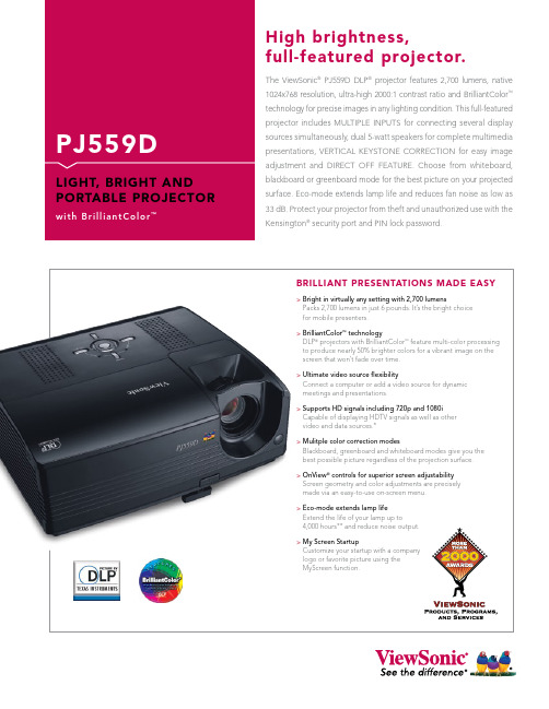
The ViewSonic ® PJ559D DLP ® projector features 2,700 lumens, native 1024x768 resolution, ultra-high 2000:1 contrast ratio and BrilliantColor ™ technology for precise images in any lighting condition. This full-featured projector includes MULTIPLE INPUTS for connecting several displaysources simultaneously, dual 5-watt speakers for complete multimedia presentations, VERTICAL KEYSTONE CORRECTION for easy image adjustment and DIRECT OFF FEATURE. Choose from whiteboard, blackboard or greenboard mode for the best picture on your projected surface. Eco-mode extends lamp life and reduces fan noise as low as 33 dB. Protect your projector from theft and unauthorized use with the Kensington ® security port and PIN lock password.High brightness,full-featured projector.PJ559DL I G H T, B R I G H T A N D P O R TA B L E P R O J E C T O R W I T H B r i l l i a n t C o l o r ™PROJECTOR Type0.55 DDR DMD, DLP ®DIsPLAy Size27.2"–250" (diagonally)AUDIO Speakers 2x5-wattINPUT sIGNAL Computer and Video RGB analog, NTSC, NTSC 4.43, P AL, SECAM, HDTV (480p, 720p, 1080i) Frequency F h :31–79kHz; F v :56–85HzCOmPATIBILITy PCAnalog: from VGA up to SXGA (scaled)Mac ®†Analog: up to SXGA CONNECTOR RGB (input/output) 15-pin HD, D-sub (x2)UsB Type B for mouse control only POWER Voltage 100–240VAC, 50–60Hz (universal)Consumption 200W (typ)CONTROLs Basic Standby/on, input, menuOnView ®Display mode, brightness, contrast, keystone, aspect ratio, blank screen, gamma, white peaking, color temperature, user color, video (sharpness, saturation, tint), display (phase,tracking, H. postion, V . postion), advance (auto source, select, rear, ceiling, eco-mode, lamp hours, lamp reset, auto shutdown, OSD timeout, menu position, factory reset),audio (audio mute)OPERATING Temperature 32–104ºF (0–40ºC)CONDITIONs Humidity 10–90% (non-condensing)Altitude0–10,000 ft.NOIsE LEVELs Normal / Eco-mode35 dB (typ) / 33 dB (typ)DImENsIONs Physical (W x H x D) 8.9" x 4.3" x 8.8" (277mm x 109mm x 223mm)WEIGHT Net 6.0 lb. (2.7 kg) Gross 13.0 lb. (5.9 kg)REGULATIONs UL/cUL, FCC-B, CE, CB, CCC, NOM, ICES 003, IRAM, TUV/GS, GOST -R, HYGIENIC, SASO, UKrSEPRO, RoHS RECyCLE/DIsPOsAL The lamp in this product contains mercury. Please dispose of in accordance with local, state or federal laws.PACKAGE CONTENTsProjector, power cable, VGA cable, S-video cable, remote control with built-in laser, soft case, lens cap, Quick StartGuide, ViewSonic Wizard CD (with User Guide)WARRANTy 3-year limited warranty on parts and labor, 1-year limitedwarranty on lamp, 1-year free Express Exchange ® service.***Sales:(888)881-8781•***********************•*Optional cables required. **Running eco-mode exclusively can extend lamp life. ***See for full details. †Adapter may be required. Analog adapter available from ViewSonic. DLP and the DLP logo are registered trademarks of Texas Instruments and BrilliantColor is a trademark of Texas Instruments. Specifications subject to change without notice. Selection, offers and programs may vary by country; see your ViewSonic representative for complete details. Corporate names, trademarks stated herein are the property of their respective companies. Copyright © 2007 ViewSonic Corporation. All rights reserved. [13727-01B-12/07] PJ559D-1ViewSonic Corporation’s QMS & EMS have been registered to ISO 9001 & ISO 14001, respectively,by the British Standards Institution.Optional Accessories• Replacement lamp ............................RLC-36• Soft case with wheels ........................CASE-006• Extended Express Exchange ® ..........PRJ-EE-05-03• Universal ceiling mount kit ...............WMK-005• VGA to component video adapter ...ADPT-002• Wireless G Presentation Gateway ....WPG-150。

1)Valid for one branch – Gültig für einen Brückenzweig 2)Valid, if the temperature of the terminals is kept to 100/CGültig, wenn die Temperatur der Anschlüsse auf 100/C gehalten wird 111.02.2003Silicon-Bridge RectifiersSilizium-BrückengleichrichterNominal current – Nennstrom 1 AAlternating input voltage 40…500 VEingangswechselspannung DIL-plastic case8.3 x 6.4 x 3.1 [mm]DIL-Kunststoffgehäuse Weight approx. – Gewicht ca.0.4 gPlastic material has UL classification 94V-0Gehäusematerial UL94V-0 klassifiziertStandard packaging: plastic tubessee page 22Standard Lieferform: Plastik-Schienen siehe Seite 22Recognized Product – Underwriters Laboratories Inc.® File E175067Anerkanntes Produkt – Underwriters Laboratories Inc.® Nr. E175067Maximum ratings GrenzwerteType Typ Alternating input voltage EingangswechselspannungV VRMS [V]Repetitive peak reverse voltage Periodische SpitzensperrspannungV RRM [V] 1)B 40D 4080B 80D 80160B 125D 125250B 250D 250600B 380D 380800B 500D5001000Repetitive peak forward current f > 15 Hz I FRM 10 A 2)Periodischer SpitzenstromPeak forward surge current, 50 Hz half sine-wave T A = 25/C I FSM 40 A Stoßstrom für eine 50 Hz Sinus-Halbwelle Rating for fusing, t < 10 ms T A = 25/Ci 2t 8A 2sGrenzlastintegral, t < 10 msOperating junction temperature – Sperrschichttemperatur T j – 50...+150/C Storage temperature – LagerungstemperaturT S– 50...+150/C1)Valid for one branch – Gültig für einen Brückenzweig2)Valid, if mounted on P.C. board with 25 mm 2 copper pads at each terminalDieser Wert gilt bei Montage auf Leiterplatte mit 25 mm 2 Kupferbelag (Lötpad) an jedem Anschluß2F:\Data\WP\DatBlatt\Einzelblätter\b40d-500d.wpdCharacteristicsKennwerteMax. average forward rectified current T A = 50/C R-load I FAV 1.0 A 2)DauergrenzstromC-load I FAV 0.8 A 2)Forward voltage – Durchlaßspannung T j = 25/C I F = 1 A V F < 1.1 V 1)Leakage current – SperrstromT j = 25/CV R = V RRMI R < 10 :A Thermal resistance junction to ambient airR thA< 60 K/W 2)Wärmewiderstand Sperrschicht – umgebende LuftType Typ Max. admissible load capacitor Max. zulässiger LadekondensatorC L [:F]Min. required protective resistor Min. erforderl. SchutzwiderstandR t [S ]B 40D 50000.8B 80D 2500 1.6B 125D 1500 2.5B 250D 800 5.0B 380D 6008.0B 500D40010。
美的R05D/BG型号遥控器电控功能规格书 8235项目(V1.0 2008-07-17)编制: 廖潮斌校对:审核:会签:批准:目录:1、功能概述2、关键词说明3、液晶显示及图形定义4、各按键技术要求5、跳线选择6、编码规范7、性能参数8、遥控器R05按键示意图版本说明:V1.0 2008-07-171、修正功能规格书2、增加随身感功能复用键3、增加自清洗功能复用键4、增加负离子功能复用键一、功能概述1、自动、制冷、制热、抽湿、送风功能设定2、二十四小时定时开机或关机功能3、温度设定范围:17℃~30℃(76℉~88℉)4、全功能LCD显示5、电辅热/强劲功能控制6、风向和换气功能控制7、具有单冷/冷暖选择端、中风/无中风选择端、华氏/摄氏温度选择端及是否取消压缩机三分钟延时保护选择8、遥控器发射码与东芝(TOSHIBA)的编码格式兼容9、背光功能。
在开机或关机状态下,任何一次有效按键后背光点亮3秒,如在3秒内有其它键按下,则以最后一次按键算起,背光点亮3秒。
二、关键词说明1、复位状态1.1 首次装上电池、刚接通电源或按下复位键后,遥控器进入的状态称为复位状态。
1.2 进入复位状态后,液晶显示屏全部笔画点亮两秒钟,然后关闭全部笔画一秒钟,最后显示默认设置状态。
遥控器默认设置状态如下:①. 功能选择-- 自动模式区相应箭头指向“自动”字样②. 温度选择-- 24℃/76℉③. 风速选择-- 自动1.3 复位后,遥控器处在关机状态,开机指示熄灭。
1.4 复位后,无定时开机或定时关机信息。
若调整定时开、关时间,则第一次显示时,定时开、关时间均为0小时。
1.5 复位后,时钟处于调整状态,初始设定时间为12:00。
2、关机状态2.1 开机指示图形熄灭时,遥控器所处的状态为关机状态。
2.2 关机状态下,运行模式、风速、设定温度等信息均可以调整,且控制方式与开机状态相同,但不发射遥控信息。
2.3 关机状态下,定时开关信息可以调整,每次有效的按键操作都以红外信息发射相应的遥控信息。