WYL0200010 以太网基础 教师参考
- 格式:doc
- 大小:48.00 KB
- 文档页数:4
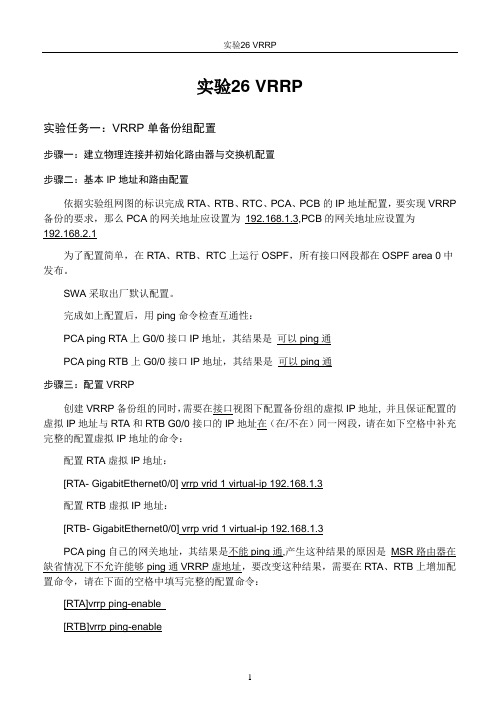
实验26 VRRP实验任务一:VRRP单备份组配置步骤一:建立物理连接并初始化路由器与交换机配置步骤二:基本IP地址和路由配置依据实验组网图的标识完成RTA、RTB、RTC、PCA、PCB的IP地址配置,要实现VRRP 备份的要求,那么PCA的网关地址应设置为192.168.1.3,PCB的网关地址应设置为192.168.2.1为了配置简单,在RTA、RTB、RTC上运行OSPF,所有接口网段都在OSPF area 0中发布。
SWA采取出厂默认配置。
完成如上配置后,用ping命令检查互通性:PCA ping RTA上G0/0接口IP地址,其结果是可以ping通PCA ping RTB上G0/0接口IP地址,其结果是可以ping通步骤三:配置VRRP创建VRRP备份组的同时,需要在接口视图下配置备份组的虚拟IP地址, 并且保证配置的虚拟IP地址与RTA和RTB G0/0接口的IP地址在(在/不在)同一网段,请在如下空格中补充完整的配置虚拟IP地址的命令:配置RTA虚拟IP地址:[RTA- GigabitEthernet0/0] vrrp vrid 1 virtual-ip 192.168.1.3配置RTB虚拟IP地址:[RTB- GigabitEthernet0/0] vrrp vrid 1 virtual-ip 192.168.1.3PCA ping自己的网关地址,其结果是不能ping通,产生这种结果的原因是MSR路由器在缺省情况下不允许能够ping通VRRP虚地址,要改变这种结果,需要在RTA、RTB上增加配置命令,请在下面的空格中填写完整的配置命令:[RTA]vrrp ping-enable[RTB]vrrp ping-enable接下来配置备份组优先级以确保在初始情况下,RTA为Master路由器承担业务转发,在MSR路由器上VRRP备份组的缺省优先级是100,要确保RTA为VRRP备份组Master路由器,那么RTA在该备份组中的优先级应该大于(大于/小于)RTB在该备份组中的优先级。


目录第1章产品介绍.....................................................................................................................1-11.1 产品简介.............................................................................................................................1-11.2 功能特性列表.....................................................................................................................1-1第2章登录以太网交换机.......................................................................................................2-12.1 通过Console口搭建配置环境...........................................................................................2-12.2 通过Telnet搭建配置环境..................................................................................................2-32.2.1 通过微机Telnet到以太网交换机.............................................................................2-32.2.2 通过以太网交换机Telnet到以太网交换机..............................................................2-42.3 通过Modem拨号搭建配置环境.........................................................................................2-5第3章命令行接口..................................................................................................................3-13.1 命令行接口.........................................................................................................................3-13.2 命令行视图.........................................................................................................................3-13.3 命令行特性.........................................................................................................................3-43.3.1 命令行在线帮助.......................................................................................................3-43.3.2 命令行显示特性.......................................................................................................3-53.3.3 命令行历史命令.......................................................................................................3-53.3.4 命令行错误信息.......................................................................................................3-63.3.5 命令行编辑特性.......................................................................................................3-6第4章用户界面配置..............................................................................................................4-14.1 用户界面简介.....................................................................................................................4-14.2 用户界面配置.....................................................................................................................4-24.2.1 进入用户界面视图....................................................................................................4-24.2.2 配置用户界面支持的协议.........................................................................................4-24.2.3 配置AUX(即Console)口属性.............................................................................4-34.2.4 配置终端属性...........................................................................................................4-44.2.5 用户管理..................................................................................................................4-64.2.6 配置重定向功能.......................................................................................................4-94.3 用户界面显示和调试........................................................................................................4-10第5章系统IP配置................................................................................................................5-15.1 系统IP简介.......................................................................................................................5-15.1.1 管理VLAN...............................................................................................................5-15.1.2 IP地址.....................................................................................................................5-15.1.3 静态路由..................................................................................................................5-35.2 系统IP配置.......................................................................................................................5-35.2.1 创建/删除管理VLAN接口.......................................................................................5-45.2.2 为管理VLAN接口指定/删除IP地址.......................................................................5-45.2.3 为管理VLAN接口指定描述字符.............................................................................5-45.2.4 打开/关闭管理VLAN接口.......................................................................................5-55.2.5 配置主机名和对应的IP地址....................................................................................5-55.2.6 配置静态路由...........................................................................................................5-55.2.7 配置静态路由的缺省优先级.....................................................................................5-6 5.3 系统IP显示和调试.............................................................................................................5-6第1章产品介绍1.1 产品简介Quidway S2100-EI系列以太网交换机是为要求具备高性能、较大端口密度且易于安装的网络环境而设计的智能型可网管交换机。

Wireless N 300+ Powerline AV Router WNXR2000Inc. All rights reserved.©2010 NETGEAR,Technical SupportThank you for selecting NETGEAR products.Locate the serial number on the label of your product and use it to register your product at /register. Registration is required before you can use the telephone support service. Registration at the NETGEAR website is strongly recommended.Go to for product updates and Web support. For complete DoC please visit the NETGEAR EU Declarations of Conformity website at:/app/answers/detail/a_id/ 11621/TrademarksNETGEAR, the NETGEAR logo, ProSafe, Smart Wizard, and Auto Uplink are trademarks or registered trademarks of NETGEAR, Inc. Microsoft, Windows, Windows NT, and Vista are registered trademarks of Microsoft Corporation. Other brand and product names are registered trademarks or trademarks of their respective holders.Statement of ConditionsIn the interest of improving internal design, operational function, and/or reliability, NETGEAR reserves the right to make changes to the products described in this document without notice. NETGEAR does not assume any liability that may occur due to the use or application of the product(s) or circuit layout(s) described herein.Resource CDAbout Your WNXR2000The WNR2000 router works with the XAVP1000 Y-cableadapter to help you create a Powerline and wireless network.To set up your network, do the following:• Set Up the XAVP1000 Adapter• Connect the WNXR2000 Powerline AV RouterSet Up the XAVP1000 AdapterFollow these steps to connect the XAVP1000 adapter to therouter:1. Plug the network connector on the Y-cable adapter into oneof the orange Ethernet ports on the router.2. Plug the Power connector on the Y-cable adapter into thepower inlet on the router.3. Plug the XAVP1000 adapter into an electrical outlet.Make sure that:• You do NOT plug the adapter into a Power Strip.• The electrical outlet is not controlled by a wall switch to avoid someone unknowingly turning off the power tothe outlet.4. Power on the router using the Power On/Off button on theback of the router.5. Check that the power lights on both the XAVP1000 adapterand on the router are lit. For more information on the status lights, see “WNXR2000 Router Status Lights” on page15 and “XAVP1000 Adapter LEDs and Buttons” on page17.6. When the router indicates that the Ethernet port connected tothe Y-cable adapter is linked and active (the LED for theEthernet port on the front of the router will be solid green), check that the Ethernet and Powerline LEDs on the adapter are also on and blinking.Connect the WNXR2000Powerline AV RouterFollow the connection instructions as shown in the drawing on the next page.Step 4:Power on your router.Wait until the wireless LEDturns on.Power on your modem.Wait until your modemcycles on (approximately2 minutes).Note: If you have a modem with a battery-backup, remove and re-insert the battery before connecting your modem to power.Resource CDStep 6:This drawing (Room 1) shows how the Y-cable Powerline adapter and WNR2000 router might fit into an existingSetting Up Internet Access1. In the address field of your browser, type http:// and click Enter.2. Enter the router User Nameadmin and default Passwordpassword to open yourrouter’s main settings page.3. When the main settingspage opens, you will beasked if you want to “Checkfor Update.” Click Cancel.You can always check for newfirmware later after you are connected to the Internet.4. Select the first menu item on the left: Setup Wizard. Makesure Yes is selected. Then click Next and follow the prompts to complete the Setup Wizard.When the Setup Wizard has completed detecting yourconnection, the Basic Settings page displays showing your settings. You are now connected to the Internet.Note: If your ISP requires that you enter a User Name or Password, you will be prompted to enter this information.If you do not have this information, contact your ISP. After connecting to the Internet, you can check for firmware updates by selecting Router Upgrade and following the on-screen prompts.Setting Up the Wireless SecurityYou should set up a secure wireless network. Once your router security is established, your wireless laptops, gaming devices (such as Wii or Play station 3 with wireless), or other wireless equipment can safely and securely connect to the Internet.1. From the main menu page, select Wireless Settings.**Your router menu may display different or additional featuresnot shown2. First, name your wireless network. Choose a name that iseasy for you to remember. You might want to write it down here: ___________________________ (the default name is NETGEAR).3. Select your security method. NETGEAR recommends WPA-PSK (TKIP) +WPA2-PSK (AES). Then, enter a Passphrase. In the example, we entered HomeNetwork.You might want to write your Passphrase downhere:________________________.Note: Both your Network Name (SSID) and Passphrase arecase sensitive. Your Network name, Security method andPassphrase must be the same on all the wireless devicesconnected to your router.4. Click Apply and close your browser.Connecting Wireless Devices to Your RouterIf you don’t remember your Passphrase, type http:// into your browser and log in by(defaultis entering your User Name admin and Passwordpassword). Then, select Wireless Settings to retrieve your Passphrase.You can add wireless computers and other equipment to yourwireless network:1. Open the wireless software that manages your wirelessconnections on the wireless device (iPhone, laptopcomputer, gaming device) that you want to connect to your router.2. The wireless software will scan for all wireless networks inyour area. Look for your network—the one you named when you set up your router. Select it.3. If you set up security, you will be prompted for a Passphraseor network key. Enter the Passphrase you selected and click Connect.If your wireless device supports WPS (WiFi Protected Setup)—NETGEAR calls this method Push 'N' Connect—you might be prompted to press a WPS button on the router instead of entering a Passphrase. Then:1. Press the WPS button on the router. It will look similar toor .2. Within 2 minutes, follow the wireless software instructionson the wireless device to complete the WPS process.The device will then be connected to your router. Repeat this process to add other wireless devices.LED and Button Descriptions WNXR2000 Router Status LightsInternetWireless(Ports 1 – 4)XAVP1000 Adapter LEDs and Buttons PowerlineLEDLEDWarning: Do not press the Security button on the Powerline adapter until installation is complete and the adapters are communicating with each other (indicated by the blinking Powerline LED). Pressing this button too soon can temporarily disable Powerline communication. If this should occur, use the Factory Reset button to return the Powerline adapter to its factory default settings.Troubleshooting TipsTechnical SupportThank you for selecting NETGEAR products.After installing your device, locate the serial number on thelabel of your product and use it to register your product at h ttp:// /register. Registration is required before you can use our telephone support service. Registration via ourwebsite is strongly recommended.Go to for product updates and Web support. For additional information about setting up, configuring and using your WNXR2000, see the User Manual.GPL may be included in this product; to view the GPL license agreement go to ftp:///files/GPLnotice.pdf.TroubleshootingFor troubleshooting information, see the WNXR2000 UserManual. A link is located on the Resource CD.This symbol was placed in accordance with the European Union Directive2002/96 on the Waste Electrical and Electronic Equipment (the WEEEDirective). If disposed of within the European Union, this product should betreated and recycled in accordance with the laws of your jurisdictionimplementing the WEEE Directive.© 2010 by NETGEAR, Inc. All rights reserved. NETGEAR and the NETGEAR logo are registered trademarks of NETGEAR, Inc. in the United States and/or other countries. Other brand and product names are trademarks or registered trademarks of their respective holders. Information is subject to change without notice.NETGEAR, Inc.350 East Plumeria Drive San Jose, CA 95134 USASeptember 2010。

教学流程设计(理实一体化)
教学流程设计(理实一体化)
教学流程设计(理实一体化)
教学流程设计(理实一体化)
教学流程设计(理实一体化)
教学流程设计(理实一体化)
教学流程设计(理实一体化)
教学流程设计(理实一体化)
教学流程设计(理实一体化)
教学流程设计(理实一体化)
教学流程设计(理实一体化)
教学流程设计(理实一体化)
教学流程设计(理实一体化)
教学流程设计(理实一体化)
教学流程设计(理实一体化)
教学流程设计(理实一体化)
教学流程设计(理实一体化)
教学流程设计(理实一体化)
教学流程设计(理实一体化)
教学流程设计(理实一体化)。
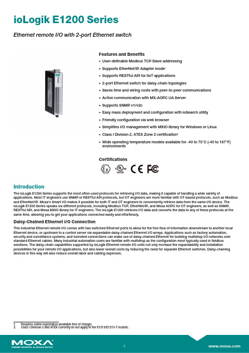
ioLogik E1200SeriesEthernet remote I/O with2-port Ethernet switchFeatures and Benefits•User-definable Modbus TCP Slave addressing•Supports EtherNet/IP Adapter mode1•Supports RESTful API for IIoT applications•2-port Ethernet switch for daisy-chain topologies•Saves time and wiring costs with peer-to-peer communications•Active communication with MX-AOPC UA Server•Supports SNMP v1/v2c•Easy mass deployment and configuration with ioSearch utility•Friendly configuration via web browser•Simplifies I/O management with MXIO library for Windows or Linux•Class I Division2,ATEX Zone2certification2•Wide operating temperature models available for-40to75°C(-40to167°F)environmentsCertificationsIntroductionThe ioLogik E1200Series supports the most often-used protocols for retrieving I/O data,making it capable of handling a wide variety of applications.Most IT engineers use SNMP or RESTful API protocols,but OT engineers are more familiar with OT-based protocols,such as Modbus and EtherNet/IP.Moxa's Smart I/O makes it possible for both IT and OT engineers to conveniently retrieve data from the same I/O device.The ioLogik E1200Series speaks six different protocols,including Modbus TCP,EtherNet/IP,and Moxa AOPC for OT engineers,as well as SNMP, RESTful API,and Moxa MXIO library for IT engineers.The ioLogik E1200retrieves I/O data and converts the data to any of these protocols at the same time,allowing you to get your applications connected easily and effortlessly.Daisy-Chained Ethernet I/O ConnectionThis industrial Ethernet remote I/O comes with two switched Ethernet ports to allow for the free flow of information downstream to another local Ethernet device,or upstream to a control server via expandable daisy-chained Ethernet I/O arrays.Applications such as factory automation, security and surveillance systems,and tunneled connections can make use of daisy-chained Ethernet for building multidrop I/O networks over standard Ethernet cables.Many industrial automation users are familiar with multidrop as the configuration most typically used in fieldbus solutions.The daisy-chain capabilities supported by ioLogik Ethernet remote I/O units not only increase the expandability and installation possibilities for your remote I/O applications,but also lower overall costs by reducing the need for separate Ethernet switches.Daisy-chaining devices in this way will also reduce overall labor and cabling expenses.1.Requires online registration(available free of charge)2.Class I Division2and ATEX currently do not apply to the E1213/E1213-T models.Save Time and Wiring Costs with Peer-to-Peer CommunicationsIn remote automation applications,the control room and sensors areoften far removed,making wiring over long distances a constantchallenge.With peer-to-peer networking,users may now map a pairof ioLogik Series modules so that input values will be directlytransferred to output channels,greatly simplifying the wiring processand reducing wiring costs.User-Definable Modbus TCP Addressing for Painless Upgrading of Existing SystemsFor Modbus devices that are controlled and detected by fixedaddresses,users need to spend a vast amount of time researchingand verifying initial ers need to locate each device’snetworking details,such as I/O channels or vendor-definedaddresses,to enable the initial or start address of a SCADA system orPLC.Devices that support user-definable Modbus TCP addressingoffer greater flexibility and easier setup.Instead of worrying aboutindividual devices,users simply configure the function and addressmap to fit their needs.Push Technology for EventsWhen used with MX-AOPC UA Server,devices can use active pushcommunications when communicating changes in state and/orevents to a SCADA system.Unlike a polling system,when using apush architecture for communications with a SCADA system,messages will only be delivered when changes in state or configuredevents occur,resulting in higher accuracy and lower amounts of datathat need to be transferred.SpecificationsInput/Output InterfaceAnalog Input Channels ioLogik E1240models:8ioLogik E1242models:4Analog Output Channels ioLogik E1241models:4Configurable DIO Channels(by jumper)ioLogik E1212models:8ioLogik E1213/E1242models:4Digital Input Channels ioLogik E1210models:16ioLogik E1212/E1213models:8ioLogik E1214models:6ioLogik E1242models:4Digital Output Channels ioLogik E1211models:16ioLogik E1213models:4Isolation3k VDC or2k VrmsRelay Channels ioLogik E1214models:6RTD Channels ioLogik E1260models:6Thermocouple Channels ioLogik E1262models:8Buttons Reset buttonDigital InputsConnector Screw-fastened Euroblock terminalCounter Frequency250HzDigital Filtering Time Interval Software configurableDry Contact On:short to GNDOff:openI/O Mode DI or event counterPoints per COM ioLogik E1210/E1212models:8channelsioLogik E1213models:12channelsioLogik E1214models:6channelsioLogik E1242models:4channelsSensor Type Dry contactWet Contact(NPN or PNP)Wet Contact(DI to COM)On:10to30VDCOff:0to3VDCDigital OutputsConnector Screw-fastened Euroblock terminalCurrent Rating ioLogik E1211/E1212/E1242models:200mA per channelioLogik E1213models:500mA per channelI/O Mode DO or pulse outputI/O Type ioLogik E1211/E1212/E1242models:SinkioLogik E1213models:SourceOver-Current Protection ioLogik E1211/E1212/E1242models:2.6A per channel@25°CioLogik E1213models:1.5A per channel@25°COver-Temperature Shutdown175°C(typical),150°C(min.)Over-Voltage Protection35VDCPulse Output Frequency500Hz(max.)RelaysBreakdown Voltage500VACConnector Screw-fastened Euroblock terminalContact Current Rating Resistive load:5A@30VDC,250VAC,110VACContact Resistance100milli-ohms(max.)Electrical Endurance100,000operations@5A resistive loadInitial Insulation Resistance1,000mega-ohms(min.)@500VDCMechanical Endurance5,000,000operationsPulse Output Frequency0.3Hz at rated load(max.)Type Form A(N.O.)power relayNote Ambient humidity must be non-condensing and remain between5and95%.The relaysmay malfunction when operating in high condensation environments below0°C. Analog InputsAccuracy ioLogik E1240/E1242:±0.1%FSR@25°C±0.3%FSR@-10to60°CioLogik E1240-T/E1242-T:±0.1%FSR@25°C±0.3%FSR@-10to60°C±0.5%FSR@-40to75°CBuilt-in Resistor for Current Input120ohmsConnector Screw-fastened Euroblock terminalI/O Mode Voltage/CurrentI/O Type DifferentialInput Impedance10mega-ohms(min.)Input Range0to10VDC0to20mA4to20mA4to20mA(with burn-out detection)Resolution16bitsSampling Rate All channels:12samples/secPer channel:1.5samples/secAnalog OutputsAccuracy ioLogik E1241:±0.1%FSR@25°C±0.3%FSR@-10to60°CioLogik E1241-T:±0.1%FSR@25°C±0.3%FSR@-40to75°CConnector Screw-fastened Euroblock terminalVoltage Output Short-Circuit Protection10mAInternal Resistor400ohmsNote:24V of external power required when loading exceeds1000ohmsOutput Range0to10VDC4to20mAResolution12-bitRTDsAccuracy ioLogik E1260:±0.1%FSR@25°C±0.3%FSR@-10to60°CioLogik E1260-T:±0.1%FSR@25°C±0.3%FSR@-40to75°CConnector Screw-fastened Euroblock terminalInput Connection2-or3-wireInput Impedance625kilo-ohms(min.)Sensor Type PT1000(-200to350°C)PT50,PT100,PT200,PT500(-200to850°C)Resistance Type310,620,1250,and2200ohmsResolution0.1°C or0.1ohmsSampling Rate All channels:12samples/secPer channel:2samples/secThermocouplesMillivolt Accuracy ioLogik E1262:±0.1%FSR@25°C±0.3%FSR@-10to60°CioLogik E1262-T:±0.1%FSR@25°C±0.3%FSR@-40to75°CConnector Screw-fastened Euroblock terminalTC Accuracy Types J,T,E,S,B:±5°CTypes K,R,N:±8°CCJC Accuracy±0.5°C@25°C±1.5°C@-40to75°CInput Impedance10mega-ohms(min.)Millivolt Type±19.532mV±39.062mV±78.126mVFault and over-voltage protection:-35to+35VDC(power off);-25to+30VDC(poweron)Resolution16bitsSampling Rate All channels:12samples/secPer channel:1.5samples/secSensor Type J,K,T,E,R,S,B,NEthernet Interface10/100BaseT(X)Ports(RJ45connector)2,1MAC address(Ethernet bypass)Magnetic Isolation Protection 1.5kV(built-in)Ethernet Software FeaturesConfiguration Options Web Console(HTTP),Windows Utility(ioSearch)Industrial Protocols EtherNet/IP Adapter(Slave),Modbus TCP Server(Slave),Moxa AOPC(Active Tag),MXIO LibraryManagement BOOTP,RESTful API,DHCP Client,HTTP,IPv4,TCP/IP,UDP,SNMPv1Trap,SNMPv1/v2cMIB Device Settings MIBSecurity Access control listLED InterfaceLED Indicators Power,Ready,Port1,Port2Modbus TCPFunctions Supported1,2,3,4,5,6,15,16,23Mode ServerMax.No.of Client Connections10EtherNet/IPMode AdapterMax.No.of Scanner Connections9(for read-only),1(for read/write)Power ParametersPower Connector Screw-fastened Euroblock terminalNo.of Power Inputs1Input Voltage12to36VDCPower Consumption ioLogik E1210Series:110mA@24VDCioLogik E1211Series:200mA@24VDCioLogik E1212Series:155mA@24VDCioLogik E1213Series:130mA@24VDCioLogik E1214Series:188mA@24VDCioLogik E1240Series:121mA@24VDCioLogik E1241Series:194mA@24VDCioLogik E1242Series:139mA@24VDCioLogik E1260Series:110mA@24VDCioLogik E1262Series:118mA@24VDCPhysical CharacteristicsHousing PlasticDimensions27.8x124x84mm(1.09x4.88x3.31in)Weight200g(0.44lb)Installation DIN-rail mounting,Wall mountingWiring I/O cable,16to26AWGPower cable,12to24AWGEnvironmental LimitsOperating Temperature Standard Models:-10to60°C(14to140°F)Wide Temp.Models:-40to75°C(-40to167°F)Storage Temperature(package included)-40to85°C(-40to185°F)Ambient Relative Humidity5to95%(non-condensing)Altitude2000m3Standards and CertificationsEMC EN55032/24,EN61000-6-2/-6-4EMI CISPR32,FCC Part15B Class AEMS IEC61000-4-2ESD:Contact:4kV;Air:8kVIEC61000-4-3RS:80MHz to1GHz:10V/mIEC61000-4-4EFT:Power:2kV;Signal:1kVIEC61000-4-5Surge:Power:2kV;Signal:1kVIEC61000-4-6CS:10VIEC61000-4-8PFMFHazardous Locations ATEX,Class I Division24Safety UL508Shock IEC60068-2-27Freefall IEC60068-2-32Vibration IEC60068-2-6DeclarationGreen Product RoHS,CRoHS,WEEEMTBFTime ioLogik E1210Series:671,345hrsioLogik E1211Series:923,027hrsioLogik E1212Series:561,930hrsioLogik E1213Series:715,256hrsioLogik E1214Series:808,744hrsioLogik E1240Series:474,053hrsioLogik E1241Series:888,656hrsioLogik E1242Series:502,210hrsioLogik E1260Series:660,260hrsioLogik E1262Series:631,418hrsStandards Telcordia SR332WarrantyWarranty Period ioLogik E1214:2years5ioLogik E1210/E1211/E1212/E1213/E1240/E1241/E1242/E1260/E1262:5years Details See /warrantyPackage ContentsDevice1x ioLogik E1200Series remote I/OInstallation Kit1x terminal block,8-pin,3.81mm1x terminal block,12-pin,3.81mm1x terminal block,3-pin,5.00mmDocumentation1x quick installation guide1x warranty card3.Please contact Moxa if you require products guaranteed to function properly at higher altitudes.4.ATEX and Class I Division2currently do not apply to the ioLogik E1213/E1213-T models.5.Because of the limited lifetime of power relays,products that use this component are covered by a2-year warranty.DimensionsOrdering InformationModel Name Input/Output Interface Digital Output Type Operating Temp. ioLogik E121016x DI–-10to60°C ioLogik E1210-T16x DI–-40to75°C ioLogik E121116x DO Sink-10to60°C ioLogik E1211-T16x DO Sink-40to75°C ioLogik E12128x DI,8x DIO Sink-10to60°C ioLogik E1212-T8x DI,8x DIO Sink-40to75°C ioLogik E12138x DI,4x DO,4x DIO Source-10to60°C ioLogik E1213-T8x DI,4x DO,4x DIO Source-40to75°C ioLogik E12146x DI,6x Relay–-10to60°C ioLogik E1214-T6x DI,6x Relay–-40to75°C ioLogik E12408x AI–-10to60°C ioLogik E1240-T8x AI–-40to75°C ioLogik E12414x AO–-10to60°C ioLogik E1241-T4x AO–-40to75°C ioLogik E12424DI,4x DIO,4x AI Sink-10to60°C ioLogik E1242-T4DI,4x DIO,4x AI Sink-40to75°C ioLogik E12606x RTD–-10to60°C ioLogik E1260-T6x RTD–-40to75°C ioLogik E12628x TC–-10to60°C ioLogik E1262-T8x TC–-40to75°CAccessories(sold separately)SoftwareMX-AOPC UA Server OPC UA Server software for converting fieldbus to the OPC UA standard©Moxa Inc.All rights reserved.Updated Aug01,2019.This document and any portion thereof may not be reproduced or used in any manner whatsoever without the express written permission of Moxa Inc.Product specifications subject to change without notice.Visit our website for the most up-to-date product information.。
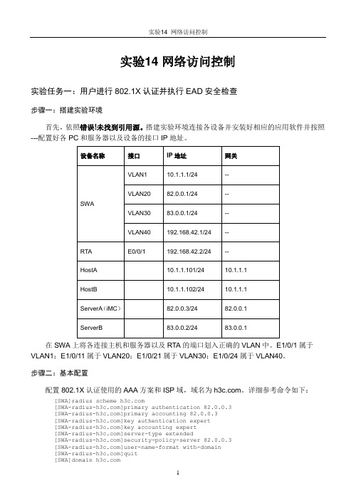
实验14 网络访问控制实验任务一:用户进行802.1X认证并执行EAD安全检查步骤一:搭建实验环境首先,依照错误!未找到引用源。
搭建实验环境连接各设备并安装好相应的应用软件并按照---配置好各PC和服务器以及设备的接口IP地址。
在SWA上将各连接主机和服务器以及RTA的端口划入正确的VLAN中。
E1/0/1属于VLAN1;E1/0/11属于VLAN20;E1/0/21属于VLAN30;E1/0/24属于VLAN40。
步骤二:基本配置配置802.1X认证使用的AAA方案和ISP域,域名为。
详细参考命令如下:[SWA]radius scheme []primary authentication 82.0.0.3[]primary accounting 82.0.0.3[]key authentication expert[]key accounting expert[]server-type extended[]security-policy-server 82.0.0.3[]user-name-format with-domain[]quit[SWA]domain []authentication lan-access radius-scheme []authorization lan-access radius-scheme []accounting lan-access radius-scheme 在SWA全局和HostA所在的端口E1/0/1上启用802.1X认证,并记录完整的配置命令。
[SWA]dot1x[SWA]int Ethernet 1/0/1[SWA-Ethernet1/0/1]dot1x步骤三:检查配置正确性请用display radius scheme 命令查看AAA方案信息并补充如下信息:[SWA]display radius scheme SchemeName = Index = 0 Type = extendedPrimary Auth IP = 82.0.0.3 Port = 1812 State = activePrimary Acct IP = 82.0.0.3 Port = 1813 State = activeSecond Auth IP = 0.0.0.0 Port = 1812 State = blockSecond Acct IP = 0.0.0.0 Port = 1813 State = blockSecurity Policy Server IP =82.0.0.3Auth Server Encryption Key = expertAcct Server Encryption Key = expertAccounting-On packet disable, send times = 5 , interval = 3sInterval for timeout(second) = 3Retransmission times for timeout = 3Interval for realtime accounting(minute) = 12Retransmission times of realtime-accounting packet = 5Retransmission times of stop-accounting packet = 500Quiet-interval(min) = 5Username format = with-domainData flow unit = BytePacket unit = one用display domain 命令查看ISP域配置信息:[SWA]display domain Domain = State = ActiveAccess-limit = DisabledAccounting method = RequiredDefault authentication scheme : localDefault authorization scheme : localDefault accounting scheme : localLan-access authentication scheme : radius=Lan-access authorization scheme : radius=Lan-access accounting scheme : radius=Domain User Template:Idle-cut = DisabledSelf-service = Disabled还可以用display dot1x interface Ethernet 1/0/1命令查看HostA所在E1/0/1端口的802.1X信息。

教师服务电脑端新建宽带连接步骤
展开全文
因校园网络设备升级,原HBUT拨号客户端已停止使用,请各位老师、同学使用系统自带的宽带连接进行拨号上网。
具体操作步骤如下所示。
一、Windows10 新建宽带连接
1、打开开始菜单,选择设置功能。
2、在Windows设置中选择网络和Internet功能。
3、在网络和Internet功能中,找到左侧菜单,选择拨号功能。
4、在拨号功能中,选择设置新连接。
5、在设置连接或网络中,选择连接到Internet选项。
6、在连接到Internet中,选择宽带(PPPoE)。
7、在连接到Internet中输入工号和密码,可以选择记住此密码选项,以后登录时就不需要再次输入密码。
二、Windows7 新建宽带连接
1、进入win7系统,右下角,找到网络标识。
2、点击该网络标识,弹出窗口,点击打开网络和共享中心。
3、进入网络和共享中心之后,在中部,找到设置新的连接和网络,点击。
4、进入设置连接或网络窗口,选择第一项连接到Internet。
5、转到连接internet对话框,然后选择宽带(PPoE)。
6、在接下来界面,输入工号和密码,勾选记住密码,点击连接。
7、接下来进入连接界面,等待该步骤完成之后,提示成功,那么宽带连接就创建成功了。
8、以后如果想进入宽带连接界面,开机之后,右下角找到网络标识,然后点击宽带连接,连接就能正常上网了。


许昌学院计算机科学与技术学院《计算机网络》课程实验教学手册
创新源于实践《计算机网络》
课程实验教学手册
计算机科学与技术学院《计算机网络》课程组
实验手册使用及要求
实验操作是教学过程中理论联系实际的重要环节,而实验报告的撰写又是知识系统化的吸收和升华过程,因此,实验报告应该体现完整性、规范性、正确性、有效性。
现将实验报告撰写的有关内容说明如下:
1、实验预习报告必须在实验前完成。
2、实验时带好实验手册,指导教师签字后方可进行实验。
3、实验中认真记录,实验结束后填写实验所做内容并回答相应问题。
4、实验内容一般手写,若填写内容过多也可以打印粘贴。
5、共设计14个题目,其中必做实验8个,选做实验6个,分组进行设计和实验,详细要求参见实验指导书。
6、注意:必做实验必须完成,选做实验任选2个完成。
实验情况一览表
实验一
实验二
实验三
实验四
实验五
实验六
实验七
实验八
实验九
实验十
实验十一
实验十二
实验十三
实验十四。

以太网业务测试方法目录一、系统适应性测试 (4)1.1、上电测试 (4)1.2、各槽位适应性测试 (5)1.3、混插测试 (5)1.4、满框测试 (6)1.5、时钟盘切换测试 (6)1.6、交叉盘切换测试 (7)1.7、SDH保护倒换测试 (8)1.8、盘保护倒换测试 (9)二、网管测试 (10)2.1、告警功能测试 (10)2.2、性能统计测试 (10)2.3、配置参数测试 (11)2.4、状态上报测试 (11)2.5、控制命令测试 (12)2.6、交叉功能测试 (12)三、功能测试 (13)3.1、最小帧长度 (13)3.2、最大帧长度 (13)3.3、异常包检测 (14)3.4、特殊包传输特性 (14)3.5、端口自适应功能 (15)3.6、自动协商功能 (15)3.7、以太网帧格式测试 (16)3.8、单播帧测试 (17)3.9 组播帧测试 (18)3.10、广播帧测试 (18)3.11、静态MAC地址配置功能 (19)3.12、MAC地址动态学习功能 (20)3.13、MAC地址老化时间测试 (20)3.14、MAC地址表容量测试 (21)3.15、MAC地址学习速度测试 (22)3.16、VLAN功能测试 (23)3.16.1、用户安全隔离测试 (23)3.16.2、VLAN Trunk功能 (23)3.16.3、设备VLAN条目数量 (24)3.16.4、VLAN支持的ID标识 (25)3.16.5、VLAN优先级测试 (25)3.16.6、PVID功能 (26)3.16.7、VMAN功能 (27)3.17、水平分割测试 (27)3.18、GFP封装测试 (29)3.18.1、GFP封装帧格式 (29)3.18.2、GFP告警检测和产生 (29)3.18.3、GFP误码监测和处理 (30)3.19、LCAS功能测试 (30)3.19.1、多径传输及最大时延差测试 (30)3.19.2、多径保护 (31)3.19.3、LCAS标准性测试 (31)3.19.4、LCAS保护时间 (32)3.19.5、时隙告警保护功能 (33)3.20、流量控制(仪表到设备) (33)3.21、流量控制(设备到仪表) (34)3.22、流量控制(拥塞形成流控) (34)3.23、端口聚合 (35)3.24、端口镜像功能 (36)3.25、生成树测试 (37)3.26、快速生成树测试 (38)3.27、基于端口优先级测试 (39)3.28、二层流功能 (39)3.29、端口接收包类型配置 (40)3.30、PING功能测试 (41)3.31、端口环回检测测试 (41)3.32、LPT功能 (42)四、指标性能测试 (43)4.1、吞吐量 (43)4.2、时延 (44)4.3、过载丢包率 (45)4.4、背靠背 (45)4.5、GE光口指标 (45)4.5.1、平均发送光功率 (46)4.5.2、接收灵敏度 (46)4.5.3、中心波长测试 (47)4.5.4、光谱宽测试 (47)4.5.5、消光比测试 (48)4.5.6、上升时间测试 (48)4.5.7、下降时间测试 (49)4.5.8、数据相关抖动测试 (49)4.5.9、发送眼图 (50)五、稳定性测试 (51)六、对通组网测试 (52)6.1、常规组网测试 (52)6.2、数据文件传送 (54)6.3、多媒体应用 (54)七、环境测试 (54)7.1、温循试验 (54)7.2、高低温性能测试 (55)7.3、电源拉偏试验 (55)7.4、单盘功耗 (56)7.5、单盘重量 (56)八、一致性测试 (56)一、系统适应性测试系统适应性测试主要针对单盘与能够使用的系统和各单盘是否进行良好的配合,单盘是否能适应各种不同的组网方式和环境变化。

端口目录目录第1章以太网端口配置命令....................................................................................................1-11.1 以太网端口配置命令..........................................................................................................1-11.1.1 broadcast-suppression............................................................................................1-11.1.2 description...............................................................................................................1-11.1.3 display interface......................................................................................................1-21.1.4 display loopback-detection......................................................................................1-41.1.5 display port..............................................................................................................1-51.1.6 duplex......................................................................................................................1-61.1.7 flow-control..............................................................................................................1-61.1.8 interface...................................................................................................................1-71.1.9 loopback..................................................................................................................1-71.1.10 loopback-detection control enable........................................................................1-81.1.11 loopback-detection enable....................................................................................1-91.1.12 loopback-detection interval-time...........................................................................1-91.1.13 loopback-detection per-vlan enable....................................................................1-101.1.14 mdi.......................................................................................................................1-111.1.15 port access vlan..................................................................................................1-111.1.16 port hybrid pvid vlan............................................................................................1-121.1.17 port hybrid vlan....................................................................................................1-121.1.18 port link-type........................................................................................................1-131.1.19 port trunk permit vlan..........................................................................................1-141.1.20 port trunk pvid vlan..............................................................................................1-141.1.21 reset counters interface.......................................................................................1-151.1.22 shutdown.............................................................................................................1-161.1.23 speed...................................................................................................................1-16第2章以太网端口汇聚配置命令............................................................................................2-12.1 以太网端口汇聚配置命令...................................................................................................2-12.1.1 display link-aggregation..........................................................................................2-12.1.2 link-aggregation.......................................................................................................2-2第3章端口隔离配置命令.......................................................................................................3-13.1 端口隔离配置命令..............................................................................................................3-13.1.1 port-isolate enable...................................................................................................3-13.1.2 port-isolate uplink-port vlan.....................................................................................3-1第1章以太网端口配置命令1.1 以太网端口配置命令1.1.1 broadcast-suppression【命令】broadcast-suppression pctundo broadcast-suppression【视图】以太网端口视图【参数】pct:指定以太网端口最大广播流量的线速度百分比,取值范围为5、10、20、100,缺省值为100。
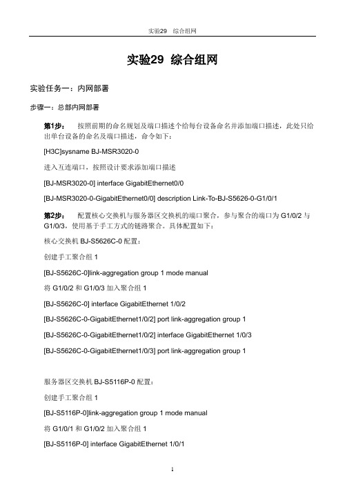
实验29 综合组网实验任务一:内网部署步骤一:总部内网部署第1步:按照前期的命名规划及端口描述个给每台设备命名并添加端口描述,此处只给出单台设备的命名及端口描述,命令如下:[H3C]sysname BJ-MSR3020-0进入互连端口,按照设计要求添加端口描述[BJ-MSR3020-0] interface GigabitEthernet0/0[BJ-MSR3020-0-GigabitEthernet0/0] description Link-T o-BJ-S5626-0-G1/0/1第2步:配置核心交换机与服务器区交换机的端口聚合,参与聚合的端口为G1/0/2与G1/0/3,使用基于手工方式的链路聚合。
具体配置如下:核心交换机BJ-S5626C-0配置:创建手工聚合组1[BJ-S5626C-0]link-aggregation group 1 mode manual将G1/0/2和G1/0/3加入聚合组1[BJ-S5626C-0] interface GigabitEthernet 1/0/2[BJ-S5626C-0-GigabitEthernet1/0/2] port link-aggregation group 1[BJ-S5626C-0-GigabitEthernet1/0/2] interface GigabitEthernet 1/0/3[BJ-S5626C-0-GigabitEthernet1/0/3] port link-aggregation group 1服务器区交换机BJ-S5116P-0配置:创建手工聚合组1[BJ-S5116P-0]link-aggregation group 1 mode manual将G1/0/1和G1/0/2加入聚合组1[BJ-S5116P-0] interface GigabitEthernet 1/0/1[BJ-S5116P-0-GigabitEthernet1/0/1] port link-aggregation group 1[BJ-S5116P-0-GigabitEthernet1/0/1] interface GigabitEthernet 1/02[BJ-S5116P-0-GigabitEthernet1/0/2] port link-aggregation group 1查看端口聚合摘要信息,验证链路聚合是否成功<BJ-S5116P-0>dis link-aggregation summaryAggregation Group Type:D -- Dynamic, S -- Static , M -- ManualLoadsharing Type: Shar -- Loadsharing, NonS -- Non-LoadsharingActor ID: 0x8000, 000f-e254-49d5AL AL Partner ID Select Unselect Share MasterID Type Ports Ports Type Port---------------------------------------------------------------------------------------------------------1 M none2 0 Shar GigabitEthernet 1/0/1第3步:根据前期的VLAN及端口分配规划,在各接入交换机上配置VLAN,并将上行接口配置为Trunk链路,允许相关VLAN通过。


以太网教案教案标题:以太网教学目标:1. 了解以太网的基本原理和组成部分。
2. 掌握以太网的传输速率以及常见的协议。
3. 掌握以太网的布线方式和常用的网络设备。
4. 能够配置和管理一个简单的以太网。
教学内容:1. 以太网的概念和基本原理。
2. 以太网的组成部分:网线、网卡、集线器、交换机等。
3. 以太网的传输速率和常用的协议:10Mbps、100Mbps、1000Mbps(千兆以太网)、TCP/IP、UDP等。
4. 以太网的布线方式:直通线、交叉线、光纤等。
5. 常用的以太网网络设备:集线器、交换机、路由器等。
6. 以太网的配置和管理:IP地址分配、子网掩码设置、网关配置等。
教学步骤:1. 导入:通过引导学生回忆日常生活中使用到的网络设备和接入方式,引发学生对以太网的兴趣。
2. 展示和讲解以太网的基本原理和组成部分,引导学生理解以太网的工作原理。
3. 分组讨论,学生根据所学内容,分析并总结以太网的传输速率和常用协议。
4. 演示以太网的布线方式和常见的网络设备,引导学生了解不同布线方式的优缺点。
5. 小组合作练习,要求学生配置和管理一个简单的以太网,包括IP地址分配、子网掩码设置、网关配置等。
6. 展示和总结学生的实际操作,让学生评价自己的配置和管理结果,并回答相关问题。
7. 拓展延伸:介绍以太网的发展历程和最新技术,展示以太网在各个领域的应用。
教学方法:1. 演示法:通过展示和讲解以太网的基本原理和组成部分,引导学生主动参与学习。
2. 合作学习:小组讨论、小组合作练习,促进学生之间的互动和合作,帮助学生深入理解所学内容。
3. 实践操作:通过配置和管理一个简单的以太网,让学生运用所学知识,提高实践操作能力。
教学评估:1. 通过小组讨论和合作练习,观察学生的表现和发言,评估学生对以太网的理解程度。
2. 监督、指导和评价学生的配置和管理操作,评估学生对以太网的实际应用能力。
3. 设计和布置相关的作业,通过书面作业等方式,评估学生对以太网的掌握程度。
网络管理与运维课程设计一、教学目标本课程的教学目标是使学生掌握网络管理与运维的基本概念、原理和方法,培养学生具备网络设备配置、网络故障排查和网络性能优化等实际操作能力。
具体目标如下:1.知识目标:(1)掌握网络基础知识,包括TCP/IP协议、网络拓扑结构等。
(2)了解网络设备的工作原理和配置方法,如路由器、交换机等。
(3)熟悉网络管理和运维的基本流程,包括网络规划、设备选型、故障排查等。
2.技能目标:(1)能够熟练操作网络设备,进行基本的配置和维护。
(2)具备网络故障的排查和解决能力,提高网络的稳定性和可靠性。
(3)掌握网络性能优化的方法,提高网络的传输效率和吞吐量。
3.情感态度价值观目标:(1)培养学生对网络管理与运维工作的热爱和敬业精神。
(2)增强学生团队合作意识,提高沟通与协作能力。
(3)培养学生积极面对挑战,持续学习的态度。
二、教学内容本课程的教学内容主要包括以下几个方面:1.网络基础知识:介绍计算机网络的基本概念、原理和常见网络拓扑结构。
2.网络设备及配置:讲解路由器、交换机等网络设备的工作原理和配置方法。
3.网络管理及运维:阐述网络管理的基本流程,包括网络规划、设备选型、故障排查等。
4.网络故障案例分析:分析常见的网络故障案例,培养学生具备故障排查和解决能力。
5.网络性能优化:介绍网络性能优化的方法和技术,提高网络的传输效率和吞吐量。
三、教学方法本课程采用多种教学方法,以激发学生的学习兴趣和主动性:1.讲授法:教师讲解基本概念、原理和方法,引导学生掌握网络管理与运维的知识体系。
2.案例分析法:分析实际网络故障案例,培养学生具备故障排查和解决能力。
3.实验法:安排实验室实践环节,让学生亲自动手操作网络设备,提高实际操作能力。
4.讨论法:学生分组讨论,培养团队合作意识和沟通协作能力。
四、教学资源为实现课程目标,我们将采用以下教学资源:1.教材:选用权威、实用的网络管理与运维教材,为学生提供系统性的知识学习。
实验3以太网基础
实验任务一:网线制作
本实验的主要任务是学员掌握网线的制作方法
步骤一:双绞线线序
双绞线由根有色导线绞合而成,按橙白、橙、绿白、蓝、蓝白、绿、棕白、棕顺时针排列,
一次编号为:1、2、3、4、5、6、7、8
如果要制作直连网线,双绞线一端的线序为1、2、3、4、5、6、7、8.那么另一端的线序
应当为1、2、3、4、5、6、7、8;如果要制作交叉网线,那么另一端的线序应当为3、6、1、4、5、2、7、8
步骤二:制作直连网线并检测连通性
按照步骤一的直连网线的制作线序,制作一条直连网线。
制作完成后,使用电缆测试仪检测电缆的连通性,检测时将双绞线两端分别插入信号发射
器和接收器,打开电源,只有同一条线的指示灯一起亮一起来的情况下,才能说明线缆连通性
良好。
步骤三:制作交叉网线并检测连通性
按照步骤一的直连网线的制作线序,制作一条交叉网线。
制作完成后,使用电缆测试仪检测电缆的连通性。
实验任务二:配置以太网双工与速率
步骤一:建立物理连接并运行超级终端
将PC(或终端)的串口通过标准Console电缆与交换机的Console口连接。
电缆的RJ-45 头一端连接交换机的Console口;9针RS-232接口一端连接计算机的串行口。
检查设备的软件版本及配置信息,确保各设备软件版本符合要求,所有配置为初始状态。
如果配置不符合要求,请学员在用户视图下擦除设备中的配置文件,然后重启设备以使系统采
用缺省的配置参数进行初始化。
步骤二:查看端口双工与速率
按照组网图,将PCA与SWA的端口E1/0/5相连,连接后,在SWA上通过display interface Ethernet 1/0/5查看接口显示状态,根据该命令输出请补充如下的空格:
Ethernet1/0/5 current state: UP
IP Packet Frame Type: PKTFMT_ETHNT_2, Hardware Address: 000f-e23e-f9b0
Media type is twisted pair, Port hardware type is 100_BASE_TX
100Mbps-speed mode, full-duplex mode
Link speed type is autonegotiation , link duplex type is autonegotiation
从如上显示信息可以看到端口的状态、物理MAC地址、连接的线缆类型以及端口的双工
与速率。
如上信息显示目前交换机默认情况下端口的双工与速率是自协商模式,协商的结果是:速
率:100M,双工模式:全双工
步骤三:修改端口速率
在SWA上将端口E1/0/5的速率修改为100M,请在如下的空格中填写完整的配置命令:
[SWA-Ethernet1/0/5]speed 100
修改完成后,再次通过命令display interface Ethernet 1/0/5查看端口Ethernet1/0/5的状
态,根据该命令输出请补充如下的空格:
100Mbps-speed mode, full-duplex mode
Link speed type is force link , link duplex type is autonegotiation
从如上显示信息可以看到,虽然端口的速率仍然是100M,但是速率模式已经是强制模式,
而不是自协商模式,而此时双工的工作模式依然是自协商。
步骤四:修改端口双工模式
在SWA上将端口E1/0/5的的双工模式配置为全双工模式,请在如下的空格中填写完整的
配置命令:
[SWA-Ethernet1/0/5]duplex full
修改完成后,再次通过命令display interface Ethernet 1/0/5查看端口Ethernet1/0/5的状
态,根据该命令输出请补充如下的空格:
Link speed type is force link, link duplex type is force link
从如上显示信息可以看到,端口虽然依然是全双工模式,但是其协商模式已经是强制模式,而不是自协商模式。
同时也可以看到,修改端口的双工模式不对端口的速率有影响。
步骤五:同时修改端口的速率与双工
在SWA上将端口Ethernet1/0/5的速率修改为10M,双工模式修改为半双工,请在如下的空格中补充完整的配置命令:
[SWA-Ethernet1/0/5]speed 10
[SWA-Ethernet1/0/5]duplex half
修改完成后,再次通过命令display interface Ethernet 1/0/5查看端口Ethernet1/0/5的状态,根据该命令输出请补充如下的空格:
10Mbps-speed mode, half-duplex mode
Link speed type is force link, link duplex type is force link
步骤六:关闭端口
在SWA上通过在接口视图下执行shutdown命令可以将端口Ethernet1/0/5关闭,
配置完成后,再次通过命令display interface Ethernet 1/0/5查看端口Ethernet1/0/5的状态,根据该命令输出请补充如下的空格:
Ethernet1/0/5 current state: Administratively DOWN
10Mbps-speed mode, half-duplex mode
Link speed type is force link , link duplex type is force link
可以看到端口被关闭,但是步骤五配置的双工模式和速率模式没有改变。
该命令只是影响
了端口的物理状态。
可以通过在接口视图下配置undo shutdown命令将端口Ethernet1/0/5开启。
实验3以太网基础...................................................................................................................................- 1 -
实验任务一:网线制作..................................................................................................................- 1 -步骤一:双绞线线序..................................................................................................................................- 1 -步骤二:制作直连网线并检测连通性.......................................................................................................- 1 -步骤三:制作交叉网线并检测连通性.......................................................................................................- 1 -实验任务二:配置以太网双工与速率..........................................................................................- 1 -步骤一:建立物理连接并运行超级终端...................................................................................................- 1 -步骤二:查看端口双工与速率...................................................................................................................- 2 -步骤三:修改端口速率..............................................................................................................................- 2 -步骤四:修改端口双工模式......................................................................................................................- 2 -步骤五:同时修改端口的速率与双工.......................................................................................................- 3 -步骤六:关闭端口......................................................................................................................................- 3 -。