1N5406-T中文资料
- 格式:pdf
- 大小:55.33 KB
- 文档页数:3

Technical Rationale for Reliability Standard TOP-001-6April 2020TOP-001-6 – Transmission OperationsRationaleRationale text from the development of TOP-001-3 in Project 2014-03 and TOP-001-4 in Project 2016-01 follows. Additional information can be found on the Project 2014-03 and Project 2016-01 pages.Rationale for Requirement R3:The phrase ‘cannot be physically implemented’ means that a Transmission Operator may request something to be done that is not physically possible due to its lack of knowledge of the system involved.Rationale for Requirement R10:New proposed Requirement R10 is derived from approved IRO-003-2, Requirement R1, adapted to the Transmission Operator Area. This new requirement is in response to NOPR paragraph 60 concerning monitoring capabilities for the Transmission Operator. New Requirement R11 covers the Balancing Authorities. Monitoring of external systems can be accomplished via data links.The revised requirement addresses directives for Transmission Operator (TOP) monitoring of some non-Bulk Electric System (BES) facilities as necessary for determining System Operating Limit (SOL) exceedances (FERC Order No. 817 Para 35-36). The proposed requirement corresponds with approved IRO-002-4 Requirement R4 (proposed IRO-002-5 Requirement R5), which specifies the Reliability Coordinator's (RC) monitoring responsibilities for determining SOL exceedances.The intent of the requirement is to ensure that all facilities (i.e., BES and non-BES) that can adversely impact reliability of the BES are monitored. As used in TOP and IRO Reliability Standards, monitoring involves observing operating status and operating values in Real-time for awareness of system conditions. The facilities that are necessary for determining SOL exceedances should be either designated as part of the BES, or otherwise be incorporated into monitoring when identified by planning and operating studies such as the Operational Planning Analysis (OPA) required by TOP-002-4 Requirement R1 and IRO-008-2 Requirement R1. The SDT recognizes that not all non-BES facilities that a TOP considers necessary for its monitoring needs will need to be included in the BES.The non-BES facilities that the TOP is required to monitor are only those that are necessary for the TOP to determine SOL exceedances within its Transmission Operator Area. TOPs perform various analyses andstudies as part of their functional obligations that could lead to identification of non-BES facilities that should be monitored for determining SOL exceedances. Examples include:∙OPA;∙Real-time Assessments (RTA);∙Analysis performed by the TOP as part of BES Exception processing for including a facility in the BES; and∙Analysis which may be specified in the RC's outage coordination process that leads the TOP to identify a non-BES facility that should be temporarily monitored for determining SOL exceedances.TOP-003-3 Requirement R1 specifies that the TOP shall develop a data specification which includes data and information needed by the TOP to support its OPAs, Real-time monitoring, and RTAs. This includes non-BES data and external network data as deemed necessary by the TOP.The format of the proposed requirement has been changed from the approved standard to more clearly indicate which monitoring activities are required to be performed.Rationale for Requirement R13:The new Requirement R13 is in response to NOPR paragraphs 55 and 60 concerning Real-time analysis responsibilities for Transmission Operators and is copied from approved IRO-008-1, Requirement R2. The Transmission Operator’s Operating Plan will describe how to perform the Real-time Assessment. The Operating Plan should contain instructions as to how to perform Operational Planning Analysis and Real-time Assessment with detailed instructions and timing requirements as to how to adapt to conditions where processes, procedures, and automated software systems are not available (if used). This could include instructions such as an indication that no actions may be required if system conditions have not changed significantly and that previous Contingency analysis or Real-time Assessments may be used in such a situation.Rationale for Requirement R14:The original Requirement R8 was deleted and original Requirements R9 and R11 were revised in order to respond to NOPR paragraph 42 which raised the issue of handling all SOLs and not just a sub-set of SOLs. The SDT has developed a white paper on SOL exceedances that explains its intent on what needs to be contained in such an Operating Plan. These Operating Plans are developed and documented in advance of Real-time and may be developed from Operational Planning Assessments required per proposed TOP-002-4 or other assessments. Operating Plans could be augmented by temporary operating guides which outline prevention/mitigation plans for specific situations which are identified day-to-day in an Operational Planning Assessment or a Real-time Assessment. The intent is to have a plan and philosophy that can be followed by an operator.FAC-011-4 R6 clarifies when an SOL exceedance is occurring and as such likely increases the number of SOL exceedances for some TOPs. This increased number of SOL exceedances could create an administrative burden on Real-Time System Operators for entities that rely on operator logs as theprimary form of evidence for compliance. This would be an unintended consequence of interaction between the new FAC-011-4 R6 and TOP-001-4 Requirement 14, which s tates, “Each Transmission Operator shall initiate its Operating Plan to mitigate a SOL exceedance identified as part of its Real-time monitoring or Real-time Assessment.” This is because TOP-001-4 Requirement 14 treats all SOL exceedances equally and does not differentiate among them based on duration or risk to the BES. Concerns were raised by drafting team members and observers as to the effect on Real-Time System Operators being required to log initiation of the Operating Plan for every SOL exceedance per TOP-001-4 R14, especially those which were considered short duration, low risk SOL exceedances that were actually successfully mitigated within a short-term time frame. This could distract Real-Time System Operators to focus on compliance documentation during times when they should be fully committed to implementing the Operating Plan and mitigating the SOL exceedance.The revised TOP-001-6 M14 addresses this concern by identifying examples of “other evidence” that can be utilized to support compliance which require less human intervention for capturing. Examples allowing TOPs to use other types of evidence such as system logs/records showing the SOL exceedance successfully mitigated in conjunction with Operating Plans is important because it clarifies that validation of successful SOL mitigation is the primary interest and focus of evidence. Successful SOL mitigation coupled with Operating Plans that have been prepared for utilization in the event of an SOL exceedance can demonstrate that the TOP initiated and implemented its Operating Plan. For example, providing outputs of State Estimator and/or Real-Time Contingency Analysis (with start time and end time of SOL exceedances) in conjunction with Operating Plans that outline roles and responsibilities between TOP and its RC in eliminating SOL exceedances, would document resolution of the SOL exceedance as well as the Operating Plan in use for the resolution. These should be sufficient evidence for Requirement R14 while reducing or eliminating the administrative burden on Real-Time System Operators to manually generate compliance evidence via logging or recording actions.These Operating Plans may be strengthened with clarifying information such as automatically switched or scheduled switching operating strategies/processes that describe how automatic control actions correct SOL exceedances, which can prevent unnecessary collection of evidence. Use of operating policies as a part of Operating Plan may include specific control actions (such as taking a transmission line out of service or disconnecting a generator for a low risk high voltage SOL exceedance) on post-contingent basis, and may be utilized if it was included into operating protocols and confirmed in real-time. Other records, such as binding constraint logs, could document the actions taken to alleviate certain thermal SOL exceedances through the role of redispatch algorithms that generate revised dispatch setpoints for generators to alleviate the constraint.Finally, further evidence may include some of the operating protocols shared between a TOP and RC as part of the Operating Plan; they may support instances where the TOP and RC agree to each take certain predetermined actions and or share information. For example, if an RC had to initiate manual redispatch with a Generator Operator when a TOP initiated binding constraint was insufficient (e.g. not fast enough), the TOP may utilize RC-provided logs as evidence of compliance if the RC and TOP have agreed to share such information. Additionally, use of these joint operating protocols as evidence recognizes situationsand operating conditions when the RC initiates and implements an Operating Plan on behalf of TOP, per these joint operating protocols. In these situations, pre-specified actions taken by the TOP and RC and agreed upon in their joint o perating protocols could allow the RC’s binding constraint logs to be used by the TOP as evidence of compliance.Rationale for Requirement R15:Clarity of what is determined to be an SOL exceedance in new revision FAC-011-4 may increase, in some instances, the number of SOL exceedances and thus the communications that are required consistent with TOP-001-4 Requirement R15 (as well as IRO-008-2 Requirement R5 and R6) which states, “Each Transmission Operator shall inform its Reliability Coordinator of actions taken to return the System to within limits when a SOL has been exceeded.”Concerns were raised as to the effect on Real-time System Operators being required to communicate every SOL exceedance, especially those which were considered short duration, low risk, SOL exceedances (e.g. less than 15 min, 30 min). This could be a significant increase for entities that historically performed RTAs more frequent than the required 30 minutes. Proposed FAC-011-4 R7 addresses this concern by requiring the RC to include in its SOL methodology a risk-based approach for determining how SOL exceedances identified as part of Real-time monitoring and Real-time Assessments must be communicated and if so, with what priority. This will ensure consistency within an RC’s area between the RC and its TOPs.The use of the terminology “in accordance with its SOL methodology, aligns the notification requirements of TOP-001-5 R15 with the communication requirements identified in FAC-011-4 Requirement R7 around communication of SOL exceedances. For example, the SOL methodology could state that an RC and TOP sharing with each other real time monitoring and RTCA output information could provide clear communication and indications of when SOL exceedances appear and are mitigated in real time, meeting the requirements of the standard.Rationale for Requirements R16 and R17:In response to IERP Report recommendation 3 on authority.Rationale for Requirement R18:Moved from approved IRO-005-3.1a, Requirement R10. Transmission Service Provider, Distribution Provider, Load-Serving Entity, Generator Operator, and Purchasing-Selling Entity are deleted as those entities will receive instructions on limits from the responsible entities cited in the requirement. Note –Derived limits replaced by SOLs for clarity and specificity. SOLs include voltage, Stability, and thermal limits and are thus the most limiting factor.Rationale for Requirements R19 and R20 (R19, R20, R22, and R23 in TOP-001-4):[Note: Requirement R19 proposed for retirement under Project 2018-03 Standards Efficiency Review Retirements.]The proposed changes address directives for redundancy and diverse routing of data exchange capabilities (FERC Order No. 817 Para 47).Redundant and diversely routed data exchange capabilities consist of data exchange infrastructure components (e.g., switches, routers, servers, power supplies, and network cabling and communication paths between these components in the primary Control Center for the exchange of system operating data) that will provide continued functionality despite failure or malfunction of an individual component within the Transmission Operator's (TOP) primary Control Center. Redundant and diversely routed data exchange capabilities preclude single points of failure in primary Control Center data exchange infrastructure from halting the flow of Real-time data. Requirement R20 does not require automatic or instantaneous fail-over of data exchange capabilities. Redundancy and diverse routing may be achieved in various ways depending on the arrangement of the infrastructure or hardware within the TOP's primary Control Center.The reliability objective of redundancy is to provide for continued data exchange functionality during outages, maintenance, or testing of data exchange infrastructure. For periods of planned or unplanned outages of individual data exchange components, the proposed requirements do not require additional redundant data exchange infrastructure components solely to provide for redundancy.Infrastructure that is not within the TOP's primary Control Center is not addressed by the proposed requirement.Rationale for Requirement R21:The proposed requirement addresses directives for testing of data exchange capabilities used in primary Control Centers (FERC Order No. 817 Para 51).A test for redundant functionality demonstrates that data exchange capabilities will continue to operate despite the malfunction or failure of an individual component (e.g., switches, routers, servers, power supplies, and network cabling and communication paths between these components in the primary Control Center for the exchange of system operating data). An entity's testing practices should, over time, examine the various failure modes of its data exchange capabilities. When an actual event successfully exercises the redundant functionality, it can be considered a test for the purposes of the proposed requirement.Rationale for Requirements R22 and R23:[Note: Requirement R22 proposed for retirement under Project 2018-03 Standards Efficiency Review Retirements]The proposed changes address directives for redundancy and diverse routing of data exchange capabilities (FERC Order No. 817 Para 47).Redundant and diversely routed data exchange capabilities consist of data exchange infrastructure components (e.g., switches, routers, servers, power supplies, and network cabling and communicationpaths between these components in the primary Control Center for the exchange of system operating data) that will provide continued functionality despite failure or malfunction of an individual component within the Balancing Authority's (BA) primary Control Center. Redundant and diversely routed data exchange capabilities preclude single points of failure in primary Control Center data exchange infrastructure from halting the flow of Real-time data. Requirement R23 does not require automatic or instantaneous fail-over of data exchange capabilities. Redundancy and diverse routing may be achieved in various ways depending on the arrangement of the infrastructure or hardware within the BA's primary Control Center.The reliability objective of redundancy is to provide for continued data exchange functionality during outages, maintenance, or testing of data exchange infrastructure. For periods of planned or unplanned outages of individual data exchange components, the proposed requirements do not require additional redundant data exchange infrastructure components solely to provide for redundancy.Infrastructure that is not within the BA's primary Control Center is not addressed by the proposed requirement.Rationale for Requirement R24:The proposed requirement addresses directives for testing of data exchange capabilities used in primary Control Centers (FERC Order No. 817 Para 51).A test for redundant functionality demonstrates that data exchange capabilities will continue to operate despite the malfunction or failure of an individual component(e.g., switches, routers, servers, power supplies, and network cabling and communication paths between these components in the primary Control Center for the exchange of system operating data). An entity's testing practices should, over time, examine the various failure modes of its data exchange capabilities. When an actual event successfully exercises the redundant functionality, it can be considered a test for the purposes of the proposed requirement.Rationale for R25: Requirement R25 was added to align the Real-time Assessments, Real-time Monitoring, and Operational Planning Analysis activities with the RC’s SOL methodology. This will ensure that methods and frameworks that surround what is required in the SOL methodology are utilized during these activities (e.g. contingencies utilized, stability criteria, performance framework, etc.) in determining SOL exceedances.。

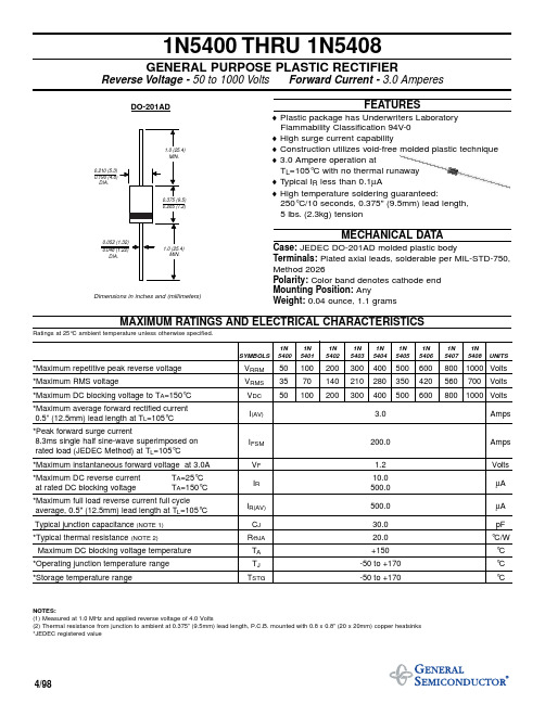
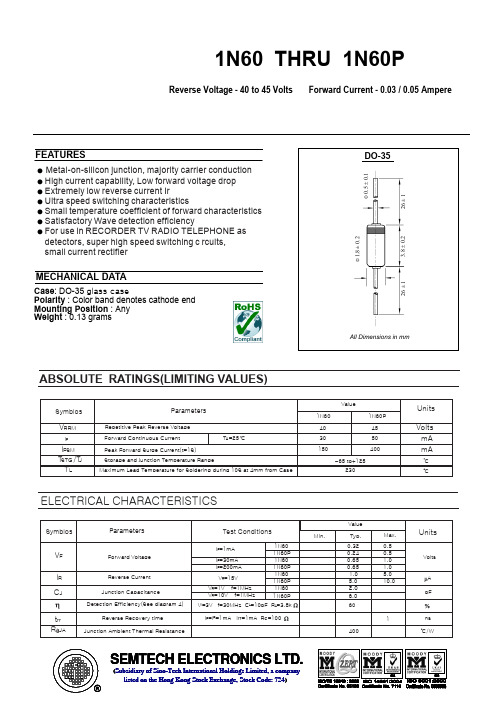
1N5400 THRU 1N5408GENERAL PURPOSE PLASTIC RECTIFIERReverse Voltage -50 to 1000 Volts Forward Current -3.0 AmperesFEATURES♦ Plastic package has Underwriters Laboratory Flammability Classification 94V-0♦ High surge current capability♦ Construction utilizes void-free molded plastic technique ♦ 3.0 Ampere operation atT L =105°C with no thermal runaway ♦ Typical I R less than 0.1µA♦ High temperature soldering guaranteed:250°C/10 seconds, 0.375" (9.5mm) lead length,5 lbs.(2.3kg) tensionMECHANICAL DATACase:JEDEC DO-201AD molded plastic bodyTerminals:Plated axial leads, solderable per MIL-STD-750,Method 2026Polarity:Color band denotes cathode end Mounting Position:AnyWeight:0.04 ounce, 1.1 gramsMAXIMUM RATINGS AND ELECTRICAL CHARACTERISTICSRatings at 25°C ambient temperature unless otherwise specified.1N 1N 1N 1N 1N 1N 1N 1N 1N SYMBOLS540054015402540354045405540654075408UNITS*Maximum repetitive peak reverse voltage V RRM 501002003004005006008001000Volts *Maximum RMS voltageV RMS 3570140210280350420560700Volts*Maximum DC blocking voltage to T A =150°C V DC 501002003004005006008001000Volts*Maximum average forward rectified current 0.5” (12.5mm) lead length at T L =105°C I (AV) 3.0Amps *Peak forward surge current8.3ms single half sine-wave superimposed on rated load (JEDEC Method) at T L =105°C I FSM 200.0Amps *Maximum instantaneous forward voltage at 3.0A V F 1.2Volts *Maximum DC reverse current T A =25°C 10.0at rated DC blocking voltageT A =150°CI R 500.0µA *Maximum full load reverse current full cycle average, 0.5" (12.5mm) lead length at T L =105°C I R(AV)500.0µA Typical junction capacitance (NOTE 1)C J 30.0pF *Typical thermal resistance (NOTE 2)R ΘJA 20.0°C/W Maximum DC blocking voltage temperature T A +150°C *Operating junction temperature range T J -50 to +170°C *Storage temperature rangeT STG-50 to +170°CNOTES:(1) Measured at 1.0 MHz and applied reverse voltage of 4.0 Volts(2) Thermal resistance from junction to ambient at 0.375” (9.5mm) lead length, P.C.B. mounted with 0.8 x 0.8” (20 x 20mm) copper heatsinks *JEDEC registered value4/98Dimensions in inches and (millimeters)。
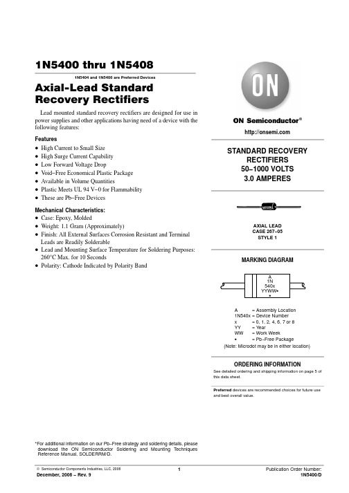
1N5400 thru 1N54081N5404 and 1N5406 are Preferred DevicesAxial−Lead Standard Recovery RectifiersLead mounted standard recovery rectifiers are designed for use in power supplies and other applications having need of a device with the following features:Features•High Current to Small Size•High Surge Current Capability•Low Forward V oltage Drop•V oid−Free Economical Plastic Package•Available in V olume Quantities•Plastic Meets UL 94 V−0 for Flammability•These are Pb−Free DevicesMechanical Characteristics:•Case: Epoxy, Molded•Weight: 1.1 Gram (Approximately)•Finish: All External Surfaces Corrosion Resistant and Terminal Leads are Readily Solderable•Lead and Mounting Surface Temperature for Soldering Purposes: 260°C Max. for 10 Seconds•Polarity: Cathode Indicated by Polarity Band*For additional information on our Pb−Free strategy and soldering details, please download the ON Semiconductor Soldering and Mounting Techniques Reference Manual, SOLDERRM/D.Preferred devices are recommended choices for future use and best overall value.A= Assembly Location1N540x= Device Numberx= 0, 1, 2, 4, 6, 7 or 8YY= YearWW= Work WeekG= Pb−Free PackageMARKING DIAGRAMA1N540xYYWW GGSee detailed ordering and shipping information on page 5 of this data sheet.ORDERING INFORMATION(Note: Microdot may be in either location)MAXIMUM RATINGSRating Symbol1N54001N54011N54021N54041N54061N54071N5408UnitPeak Repetitive Reverse Voltage Working Peak Reverse Voltage DC Blocking Voltage V RRMV RWMV R501002004006008001000VNon−repetitive Peak Reverse Voltage V RSM10020030052580010001200V Average Rectified Forward Current(Single Phase Resistive Load,1/2 in. Leads, T L = 105°C)I O 3.0ANon−repetitive Peak Surge Current(Surge Applied at Rated LoadConditions)I FSM200 (one cycle)AOperating and Storage Junction Temperature RangeT JT stg−65 to +170−65 to +175°CStresses exceeding Maximum Ratings may damage the device. Maximum Ratings are stress ratings only. Functional operation above the Recommended Operating Conditions is not implied. Extended exposure to stresses above the Recommended Operating Conditions may affect device reliability.THERMAL CHARACTERISTICSCharacteristic Symbol Typ Unit Thermal Resistance, Junction−to−Ambient (PC Board Mount, 1/2 in. Leads)R q JA53°C/WELECTRICAL CHARACTERISTICSCharacteristic Symbol Min Typ Max Unit Forward Voltage (I F = 3.0 Amp, T A = 25°C)v F−− 1.0VReverse Current (Rated DC Voltage) T A = 25°CT A = 150°C I R−−−−10100m ARatings at 25°C ambient temperature unless otherwise specified.60 Hz resistive or inductive loads.For capacitive load, derate current by 20%.NOTE 1 — AMBIENT MOUNTING DATAFigure 1. Forward Voltagev F, INSTANTANEOUS VOLTAGE (VOLTS), I N S T A N T A N E O U S F O R W AR D C U R R E N T (A M P S )F Figure 2. Maximum Nonrepetitive Surge CurrentFigure 3. Current Derating Various Lead Lengthsi 400200300401.0NUMBER OF CYCLES5060708090100 2.0 3.0 5.010Figure 4. Current Derating PC Board Mounting 7.020*********4060801001201401601808.07.06.05.04.03.02.01.004060801001201401601804.03.53.02.52.01.51.00.50T A, AMBIENT TEMPERATURE (°C)T L, LEAD TEMPERATURE (°C)I F S M , P E A K H A L F W A V E C U R R E N T (A M P S )Figure 5. Forward Power Dissipation3456789101614121086420I F(AV), AVERAGE FORWARD CURRENT (AMPS)P F (A V ), A V E R A G E P O W E R D I S S I P A T I O N (W A T T S )12ORDERING INFORMATIONDevice Package Shipping†1N5400Axial Lead*500 Units/Box1N5400G Axial Lead*500 Units/Box1N5400RL Axial Lead*1200/Tape & Reel1N5400RLG Axial Lead*1200/Tape & Reel1N5401Axial Lead*500 Units/Box1N5401G Axial Lead*500 Units/Box1N5401RL Axial Lead*1200/Tape & Reel1N5401RLG Axial Lead*1200/Tape & Reel1N5402Axial Lead*500 Units/Box1N5402G Axial Lead*500 Units/Box1N5402RL Axial Lead*1200/Tape & Reel1N5402RLG Axial Lead*1200/Tape & Reel1N5404Axial Lead*500 Units/Box1N5404G Axial Lead*500 Units/Box1N5404RL Axial Lead*1200/Tape & Reel1N5404RLG Axial Lead*1200/Tape & Reel1N5406Axial Lead*500 Units/Box1N5406G Axial Lead*500 Units/Box1N5406RL Axial Lead*1200/Tape & Reel1N5406RLG Axial Lead*1200/Tape & Reel1N5407Axial Lead*500 Units/Box1N5407G Axial Lead*500 Units/Box1N5407RL Axial Lead*1200/Tape & Reel1N5407RLG Axial Lead*1200/Tape & Reel1N5408Axial Lead*500 Units/Box1N5408G Axial Lead*500 Units/Box1N5408RL Axial Lead*1200/Tape & Reel1N5408RLG Axial Lead*1200/Tape & Reel†For information on tape and reel specifications, including part orientation and tape sizes, please refer to our Tape and Reel Packaging Specifications Brochure, BRD8011/D.*This package is inherently Pb−Free.PACKAGE DIMENSIONSAXIAL LEAD CASE 267−05ISSUE GNOTES:1.DIMENSIONING AND TOLERANCING PER ANSI Y14.5M, 1982.2.CONTROLLING DIMENSION: INCH.STYLE 1:PIN 1.CATHODE (POLARITY BAND)2.ANODEDIM MIN MAX MIN MAX MILLIMETERSINCHES A 0.2870.3747.309.50B 0.1890.209 4.80 5.30D 0.0470.051 1.20 1.30K1.000−−−25.40−−−ON Semiconductor and are registered trademarks of Semiconductor Components Industries, LLC (SCILLC). SCILLC reserves the right to make changes without further notice to any products herein. SCILLC makes no warranty, representation or guarantee regarding the suitability of its products for any particular purpose, nor does SCILLC assume any liability arising out of the application or use of any product or circuit, and specifically disclaims any and all liability, including without limitation special, consequential or incidental damages.“Typical” parameters which may be provided in SCILLC data sheets and/or specifications can and do vary in different applications and actual performance may vary over time. All operating parameters, including “Typicals” must be validated for each customer application by customer’s technical experts. SCILLC does not convey any license under its patent rights nor the rights of others. SCILLC products are not designed, intended, or authorized for use as components in systems intended for surgical implant into the body, or other applications intended to support or sustain life, or for any other application in which the failure of the SCILLC product could create a situation where personal injury or death may occur. Should Buyer purchase or use SCILLC products for any such unintended or unauthorized application, Buyer shall indemnify and hold SCILLC and its officers, employees, subsidiaries, affiliates,and distributors harmless against all claims, costs, damages, and expenses, and reasonable attorney fees arising out of, directly or indirectly, any claim of personal injury or death associated with such unintended or unauthorized use, even if such claim alleges that SCILLC was negligent regarding the design or manufacture of the part. SCILLC is an Equal Opportunity/Affirmative Action Employer. This literature is subject to all applicable copyright laws and is not for resale in any manner.PUBLICATION ORDERING INFORMATION。

PACKAGING INFORMATIONOrderable Device Status(1)PackageType PackageDrawingPins PackageQtyEco Plan(2)Lead/Ball Finish MSL Peak Temp(3)JM38510/00801BCA ACTIVE CDIP J141None Call TI Level-NC-NC-NC JM38510/00801BDA ACTIVE CFP W141None Call TI Level-NC-NC-NC SN5406J ACTIVE CDIP J141None Call TI Level-NC-NC-NC SN5416J ACTIVE CDIP J141None Call TI Level-NC-NC-NCSN7406D ACTIVE SOIC D1450Pb-Free(RoHS)CU NIPDAU Level-2-260C-1YEAR/Level-1-235C-UNLIMSN7406DR ACTIVE SOIC D142500Pb-Free(RoHS)CU NIPDAU Level-2-260C-1YEAR/Level-1-235C-UNLIMSN7406J OBSOLETE CDIP J14None Call TI Call TISN7406N ACTIVE PDIP N1425Pb-Free(RoHS)CU NIPDAU Level-NC-NC-NC SN7406N3OBSOLETE PDIP N14None Call TI Call TISN7406NSR ACTIVE SO NS142000Pb-Free(RoHS)CU NIPDAU Level-2-260C-1YEAR/Level-1-235C-UNLIMSN7416D ACTIVE SOIC D1450Pb-Free(RoHS)CU NIPDAU Level-2-260C-1YEAR/Level-1-235C-UNLIMSN7416DR ACTIVE SOIC D142500Pb-Free(RoHS)CU NIPDAU Level-2-260C-1YEAR/Level-1-235C-UNLIMSN7416N ACTIVE PDIP N1425Pb-Free(RoHS)CU NIPDAU Level-NC-NC-NC SN7416N3OBSOLETE PDIP N14None Call TI Call TISN7416NSR ACTIVE SO NS142000Pb-Free(RoHS)CU NIPDAU Level-2-260C-1YEAR/Level-1-235C-UNLIMSNJ5406FK ACTIVE LCCC FK201None Call TI Level-NC-NC-NCSNJ5406J ACTIVE CDIP J141None Call TI Level-NC-NC-NCSNJ5406W ACTIVE CFP W141None Call TI Level-NC-NC-NCSNJ5416J ACTIVE CDIP J141None Call TI Level-NC-NC-NCSNJ5416W ACTIVE CFP W141None Call TI Level-NC-NC-NC(1)The marketing status values are defined as follows:ACTIVE:Product device recommended for new designs.LIFEBUY:TI has announced that the device will be discontinued,and a lifetime-buy period is in effect.NRND:Not recommended for new designs.Device is in production to support existing customers,but TI does not recommend using this part in a new design.PREVIEW:Device has been announced but is not in production.Samples may or may not be available.OBSOLETE:TI has discontinued the production of the device.(2)Eco Plan-May not be currently available-please check /productcontent for the latest availability information and additional product content details.None:Not yet available Lead(Pb-Free).Pb-Free(RoHS):TI's terms"Lead-Free"or"Pb-Free"mean semiconductor products that are compatible with the current RoHS requirements for all6substances,including the requirement that lead not exceed0.1%by weight in homogeneous materials.Where designed to be soldered at high temperatures,TI Pb-Free products are suitable for use in specified lead-free processes.Green(RoHS&no Sb/Br):TI defines"Green"to mean"Pb-Free"and in addition,uses package materials that do not contain halogens, including bromine(Br)or antimony(Sb)above0.1%of total product weight.(3)MSL,Peak Temp.--The Moisture Sensitivity Level rating according to the JEDECindustry standard classifications,and peak solder temperature.Important Information and Disclaimer:The information provided on this page represents TI's knowledge and belief as of the date that it isprovided.TI bases its knowledge and belief on information provided by third parties,and makes no representation or warranty as to the accuracy of such information.Efforts are underway to better integrate information from third parties.TI has taken and continues to take reasonable steps to provide representative and accurate information but may not have conducted destructive testing or chemical analysis on incoming materials and chemicals.TI and TI suppliers consider certain information to be proprietary,and thus CAS numbers and other limited information may not be available for release.In no event shall TI's liability arising out of such information exceed the total purchase price of the TI part(s)at issue in this document sold by TI to Customer on an annual basis.IMPORTANT NOTICETexas Instruments Incorporated and its subsidiaries (TI) reserve the right to make corrections, modifications, enhancements, improvements, and other changes to its products and services at any time and to discontinue any product or service without notice. Customers should obtain the latest relevant information before placing orders and should verify that such information is current and complete. All products are sold subject to TI’s terms and conditions of sale supplied at the time of order acknowledgment.TI warrants performance of its hardware products to the specifications applicable at the time of sale in accordance with TI’s standard warranty. T esting and other quality control techniques are used to the extent TI deems necessary to support this warranty. Except where mandated by government requirements, testing of all parameters of each product is not necessarily performed.TI assumes no liability for applications assistance or customer product design. Customers are responsible for their products and applications using TI components. T o minimize the risks associated with customer products and applications, customers should provide adequate design and operating safeguards.TI does not warrant or represent that any license, either express or implied, is granted under any TI patent right, copyright, mask work right, or other TI intellectual property right relating to any combination, machine, or process in which TI products or services are used. Information published by TI regarding third-party products or services does not constitute a license from TI to use such products or services or a warranty or endorsement thereof. Use of such information may require a license from a third party under the patents or other intellectual property of the third party, or a license from TI under the patents or other intellectual property of TI.Reproduction of information in TI data books or data sheets is permissible only if reproduction is without alteration and is accompanied by all associated warranties, conditions, limitations, and notices. Reproduction of this information with alteration is an unfair and deceptive business practice. TI is not responsible or liable for such altered documentation.Resale of TI products or services with statements different from or beyond the parameters stated by TI for that product or service voids all express and any implied warranties for the associated TI product or service and is an unfair and deceptive business practice. TI is not responsible or liable for any such statements. Following are URLs where you can obtain information on other Texas Instruments products and application solutions:Products ApplicationsAmplifiers Audio /audioData Converters Automotive /automotiveDSP Broadband /broadbandInterface Digital Control /digitalcontrolLogic Military /militaryPower Mgmt Optical Networking /opticalnetwork Microcontrollers Security /securityTelephony /telephonyVideo & Imaging /videoWireless /wirelessMailing Address:Texas InstrumentsPost Office Box 655303 Dallas, Texas 75265Copyright 2005, Texas Instruments Incorporated。

中文使用说明书5406A数字式漏电开关RCD(ELCB)测试仪日本共立电气计器株式会社目录1.警告2.操作说明3.特点4.技术规格5.测试6.测试7.维护8.携带1.警告1.1本仪器须由受过正规训练的、合格的技术人员进行操作,并在本手册规定的条件下使用。
由于用户使用不当、或违反本手册以及安全操作规定造成的设备损坏,共立公司(Kyoritsu )将不负责任何责任。
1.2使用前请仔细阅读并领会操作指南中所规定的内容。
使用本设备时请务必遵守相关的规定。
1.3本仪器可以放心使用。
然而,任何的安全措施均无法保障由于错误使用造成的对设备或人员的损害。
对于使用者而言,如果使用中麻痹大意或缺乏必要的操作训练,可能会因为自身原因造成在使用本设备时被电击或受到其它伤害。
1.4请仔细地、完整地阅读本手册。
1.5进行测量前请仔细检查量程开关以及所有的接线。
不要直接接触裸露的导线、接头或电路中任何标有“有电”(LIVE)的部分。
2.特性2.1 测试直流(DC)Sensitive断路器。
*2.2 本设备由微处理器控制,保证了最高的精度和可靠性。
2.3 触发时间数字显示。
2.4 常值电流源电路保证了主电压的波动将不会影响读数的精度。
测试电流与主电压相独立。
2.5 三个氖管用于检测连线状态。
2.6 结构紧凑、重量轻且易于使用。
2.7 弹性包装易于携带常用配件。
2.8 零点交错(Zero cross)电路保证了在0度和180度相位时进行测试。
在上述两点可以测出最小(最佳)和最大(最差)触发时间。
2.9 最大触发时间读数2000毫秒。
3.介绍3.1 5406A使用最新的微处理器技术,从而保证了产品的最佳性能及精度。
3.2 独立常值电流控制*常值电流电路保证了即使在230伏电压波动±10%的情况下仍能正确、稳定的读数。
3.3 DC Sensitive断路器*当5406A被设定为直流模式时,该仪器将测量30mA DC Sensitive断路器。
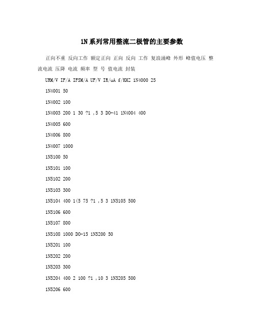
1N系列常用整流二极管的主要参数正向不重反向工作额定正向正向反向工作复浪涌峰外形峰值电压整流电流压降电流频率型号值电流封装URM/V IF/A IFSM/A UF/V IR/uA f/KHZ 1N4000 251N4001 501N4002 1001N4003 200 1 30 ?1 ,5 3 DO-41 1N4004 4001N4005 6001N4006 8001N4007 10001N5100 501N5101 1001N5102 2001N5103 3001N5104 400 1(5 75 ?1 ,5 3 1N5105 5001N5106 6001N5107 8001N5108 1000 DO-15 1N5200 501N5201 1001N5202 2001N5203 3001N5204 400 2 100 ?1 ,10 3 1N5205 5001N5206 6001N5207 8001N5208 10001N5400 501N5401 1001N5402 2001N5403 3001N5404 400 3 150 ?0.8 ,10 3 DO-271N5405 5001N5406 6001N5407 8001N5408 1000常用二极管参数:05Z6.2Y 硅稳压二极管 Vz=6~6.35V,Pzm=500mW,05Z7.5Y 硅稳压二极管 Vz=7.34~7.70V,Pzm=500mW, 05Z13X 硅稳压二极管Vz=12.4~13.1V,Pzm=500mW,05Z15Y 硅稳压二极管 Vz=14.4~15.15V,Pzm=500mW,05Z18Y 硅稳压二极管 Vz=17.55~18.45V,Pzm=500mW,稳压二极管参数大全常用稳压二极管参数代换型号稳定电压(V) 最大功电流型号国产稳压管日立稳耗(mW) (mA) 压管最小值最大值新型号旧型号 HZ4B2 500 3.8 4.0 5 2CW102 2CW21 4B2 HZ4C1 500 4.0 4.2 5 2CW102 2CW21 4C1HZ6 500 5.5 5.8 5 2CW103 2CW21A 6B1HZ6A 500 5.2 5.7 5 2CW103 2CW21A HZ6C3 500 6 6.4 5 2CW104 2CW21B 6C3 HZ7 500 6.9 7.2 5 2CW105 2CW21CHZ7A 500 6.3 6.9 5 2CW105 2CW21CHZ7B 500 6.7 7.3 5 2CW105 2CW21CHZ9A 500 7.7 8.5 5 2CW106 2CW21D HZ9CTA 500 8.9 9.7 5 2CW107 2CW21E HZ11 500 9.5 11.9 5 2CW109 2CW21GHZ12 500 11.6 14.3 5 2CW111 2CW21H HZ12B 500 12.4 13.4 5 2CW1112CW21H HZ12B2 500 12.6 13.1 5 2CW111 2CW21H 12B2 HZ18Y 500 16.5 18.5 52CW113 2CW21J HZ20-1 500 18.86 19.44 2 2CW114 2CW21KHZ27 500 27.2 28.6 2 2CW117 2CW21L 27-3 HZT33-02 400 31 33.5 52CW119 2CW21M RD2.0E(B) 500 1.88 2.12 20 2CW100 2CW21P 2B1 RD2.7E 400 2.5 2.93 20 2CW101 2CW21S RD3.9EL1 500 3.7 4 20 2CW102 2CW21 4B2RD5.6EN1 500 5.2 5.5 20 2CW103 2CW21A 6A1 RD5.6EN3 500 5.6 5.9 20 2CW104 2CW21B 6B2 RD5.6EL2 500 5.5 5.7 20 2CW103 2CW21A 6B1 RD6.2E(B) 500 5.88 6.6 20 2CW104 2CW21B RD7.5E(B) 500 7.0 7.9 20 2CW105 2CW21C RD10EN3 500 9.7 10.0 20 2CW108 2CW21F 11A2 RD11E(B) 500 10.1 11.8 15 2CW109 2CW21G RD12E 500 11.74 12.35 10 2CW110 2CW21H 12A1 RD12F 1000 11.19 11.77 202CW109 2CW21GRD13EN1 500 12 12.7 10 2CW110 2CW21H 12A3 RD15EL2 500 13.8 14.6 152CW112 2CW21J 12C3 RD24E 400 22 25 10 2CW116 2CW21H 24-1 RD24F 400 24 28 10 2CW117 2CW21L RD36EL1 500 32 34 15 2CW119 2CW21M 33-2 RD57E 500 48 54 10 1DS55-18 05Z5.1Y 500 4.94 5.20 2CW103 2CW21A 5C2 05Z5.6Z 500 5.615.91 2CW104 2CW21B 6B2 05Z6.2Y 500 5.96 6.27 41 2CW104 2CW21B 6C205Z7.5Y 500 7.07 7.45 34 2CW105 2CW21C 05Z7.5Z 500 7.3 7.7 34 2CW1052CW21C 7C2 05Z9.1Y 500 8.9 9.3 30 2CW107 2CW21E 9C1 05Z12 500 11.1312.35 21 2CW110 2CW21H 05Z12Z 500 12.0 12.6 20 2CW110 2CW21H 12A3 05Z13X500 12.11 12.75 19 2CW110 2CW21H 12A3 05Z13Z 500 13.5 14.1 18 2CW1112CW21H 12C2 05Z13Y 500 12.55 13.21 19 2CW111 2CW21H 12B2 05Z15 500 14.4 15.0 17 2CW112 2CW21J 15-2 05Z15Y 500 13.89 14.62 17 2CW111 2CW21H 12C3 05Z18 500 16.5 18.5 14 2CW113 2CW21J 05Z18Y 500 16.82 17.70 14 2CW1132CW21J 18-1 EQA01-11B 500 10.1 11.8 15 2CW109 2CW21G EQA01-12Z 500 11.2 13.1 15 2CW110 2CW21H EQA02-07B 400 6.66 7.01 20 2CW105 2CW21C 7A3EQA02-25A 500 24 25.5 2CW116 2CW21L 24-3 TVSQA106SB 500 5.88 6.6 202CW104 2CW21B TVSQA111SB 500 10.4 11.6 10 2CW109 2CW21G TVSQA111SE 500 11 11.5 10 2CW109 2CW21G 11C2 MA1130 1000 12.4 14.1 5 2CW111 2CW21HMA1330 500 31 35 25 2CW120 2CW21N M4030 500 2.9 3 5 2CW101 2CW21SuPC574JAG 200 31 35 25 2CW120 2CW21NRIMV 135 160 ZDW59快恢复二极管参数型号品牌电流电压时间极性 IN5817 GJ 1A 20V 10ns IN5819 GJ 1A 40V 10ns IN5819 MOT 1A 40V 10ns IN5822 MOT 3A 40V 10ns 21D-06 FUI 3A 60V10ns SBR360 GI 3A 60V 10ns C81-004 FUI 3A 40V 10ns 8TQ080 IR 8A 80V 10ns 单管 MBR1045 MOT 10A 45V 10ns 单管 MBR1545CT MOT 15A 45V 10ns 双管MBR1654 MOT 16A 45V 10ns 双管 16CTQ100 IR 16A 100V 10ns 双管 MBR2035CT MOT 20A 35V 10ns 双管 MBR2045CT MOT 20A 45V 10ns 双管 MBR2060CT MOT 20A 60V 10ns 双管 MBR20100CT IR 20A 100V 10ns 双管 025CTQ045 IR 25A 45V 10ns 双管 30CTQ045 IR 30A 45V 10ns 双管 C85-009* FUI 20A 90V 10ns 双管 D83-004* FUI 30A 40V 10ns 双管 D83-009* FUI 30A 90V 10ns 双管 MBR4060* IR40A 60V 10ns 双管 MBR30045 MOT 300A 45V 10ns MUR120 MOT 1A 200V 35ns MUR160 MOT 1A 600V 35ns MUR180 MOT 1A 800V 35ns MUR460 MOT 4A 600V 35nsBYV95 PHI 1.5A 1000V 250ns BYV27-50 PHI 2A 55V 25ns BYV927-100 PHI 2A 100V 25ns BYV927-300 PHI 2A 300V 25ns BYW76 PHI 3A 1000V 200ns BYT56G PHI 3A 600V 100ns BYT56M PHI 3A 1000V 100ns BYV26C PHI 1A 600V 30ns BYV26E PHI 1A 1000V 30ns FR607 GI 6A 1000V 200ns MUR8100 MOT 8A 1000V 35ns 单管HFA15TB60 IR 15A 600V 35ns 单管HFA25TB60 IR 25A 600V 35ns 单管MUR30100 HAR 30A 1000V 35ns 单管MUR30120 HAR 30A 1200V 35ns 单管MUR1620 PHI 16A 200V 35ns 双管MUR1620CT MOT 16A 200V 35ns 双管MUR1620P MOT 16A 200V 35ns 双管MUR1660CT MOT 16A 600V 35ns 双管HFA16TA600 IR 16A 600V 35ns 双管MUR3030 GI 30A 300V 35ns 双管MUR3040 MOT 30A 400V 35ns 双管MUR3060 MOT 30A 600V 35ns 双管HFA30TA600 IR 30A 600V 35ns 双管MUR20040 MOT 200A 400V 35ns 双管B92M-02 FUI 20A 200V 35ns 单管C92-02 FUI 20A 200V 35ns 双管D92M-02 FUI 30A 200V 35ns 双管D92M-03 FUI 30A 300V 35ns 双管DSE130-06 DSET 30A 600V 35ns 双管DSE160-06 DSET 60A 600V 35ns 双管稳压二极管常见稳压二极管的详细参数数据表代换型号稳定电压(V) 最大功耗电流型号国产稳压管日立稳压(mW) (mA) 管最小值最大值新型号旧型号 HZ4B2 500 3.8 4.0 5 2CW102 2CW21 4B2HZ4C1 500 4.0 4.2 5 2CW102 2CW21 4C1 HZ6 500 5.5 5.8 5 2CW103 2CW21A 6B1 HZ6A 500 5.2 5.7 5 2CW103 2CW21A HZ6C3 500 6 6.4 5 2CW104 2CW21B 6C3 HZ7 500 6.9 7.2 5 2CW105 2CW21C HZ7A 500 6.3 6.9 5 2CW105 2CW21C HZ7B 5006.77.3 5 2CW105 2CW21C HZ9A 500 7.78.5 5 2CW106 2CW21D HZ9CTA 500 8.99.7 5 2CW107 2CW21E HZ11 500 9.5 11.9 5 2CW109 2CW21G HZ12 500 11.6 14.3 5 2CW111 2CW21H HZ12B 500 12.4 13.4 5 2CW111 2CW21HHZ12B2 500 12.6 13.1 5 2CW111 2CW21H 12B2 HZ18Y 500 16.5 18.5 52CW113 2CW21J HZ20-1 500 18.86 19.44 2 2CW114 2CW21K HZ27 500 27.2 28.62 2CW117 2CW21L 27-3 HZT33-02 400 31 33.5 5 2CW119 2CW21M RD2.0E(B) 500 1.88 2.12 20 2CW100 2CW21P 2B1 RD2.7E 400 2.5 2.93 20 2CW101 2CW21SRD3.9EL1 500 3.7 4 20 2CW102 2CW21 4B2 RD5.6EN1 500 5.2 5.5 20 2CW1032CW21A 6A1 RD5.6EN3 500 5.6 5.9 20 2CW104 2CW21B 6B2 RD5.6EL2 500 5.55.7 20 2CW103 2CW21A 6B1 RD6.2E(B) 500 5.88 6.6 20 2CW104 2CW21BRD7.5E(B) 500 7.0 7.9 20 2CW105 2CW21C RD10EN3 500 9.7 10.0 20 2CW1082CW21F 11A2 RD11E(B) 500 10.1 11.8 15 2CW109 2CW21G RD12E 500 11.7412.35 10 2CW110 2CW21H 12A1 RD12F 1000 11.19 11.77 20 2CW109 2CW21GRD13EN1 500 12 12.7 10 2CW110 2CW21H 12A3 RD15EL2 500 13.8 14.6 152CW112 2CW21J 12C3 RD24E 400 22 25 10 2CW116 2CW21H 24-1 RD24F 400 24 28 10 2CW117 2CW21L RD36EL1 500 32 34 15 2CW119 2CW21M 33-2 RD57E 500 48 5410 1DS55-18 05Z5.1Y 500 4.94 5.20 2CW103 2CW21A 5C2 05Z5.6Z 500 5.615.91 2CW104 2CW21B 6B2 05Z6.2Y 500 5.96 6.27 41 2CW104 2CW21B 6C205Z7.5Y 500 7.07 7.45 34 2CW105 2CW21C 05Z7.5Z 500 7.3 7.7 34 2CW1052CW21C 7C2 05Z9.1Y 500 8.9 9.3 30 2CW107 2CW21E 9C1 05Z12 500 11.1312.35 21 2CW110 2CW21H 05Z12Z 500 12.0 12.6 20 2CW110 2CW21H 12A3 05Z13X 500 12.11 12.75 19 2CW110 2CW21H 12A3 05Z13Z 500 13.5 14.1 18 2CW1112CW21H 12C2 05Z13Y 500 12.55 13.21 19 2CW111 2CW21H 12B2 05Z15 500 14.4 15.0 17 2CW112 2CW21J 15-2 05Z15Y 500 13.89 14.62 17 2CW111 2CW21H 12C3 05Z18 500 16.5 18.5 14 2CW113 2CW21J 05Z18Y 500 16.82 17.70 14 2CW1132CW21J 18-1 EQA01-11B 500 10.1 11.8 15 2CW109 2CW21G EQA01-12Z 500 11.2 13.1 15 2CW110 2CW21HEQA02-07B 400 6.66 7.01 20 2CW105 2CW21C 7A3 EQA02-25A 500 24 25.52CW116 2CW21L 24-3 TVSQA106SB 500 5.88 6.6 20 2CW104 2CW21B TVSQA111SB 500 10.4 11.6 10 2CW109 2CW21G TVSQA111SE 500 11 11.5 10 2CW109 2CW21G 11C2 MA1130 1000 12.4 14.1 5 2CW111 2CW21H MA1330 500 31 35 25 2CW1202CW21N M4030 500 2.9 3 5 2CW101 2CW21S uPC574JAG 200 31 35 25 2CW1202CW21NRIMV 135 160 ZDW59最大耗散功最大工作型号额定电压(V) 可代换型号率(W) 电流(mA)1N708 0.25 5.6 40 BWA54、2CW28-5.6V 1N709 0.25 6.2 40 2CW55/B、BWA55/E 1N710 0.25 6.8 36 2CW55A、2CW105-6.8V2CW56A、2CW28-7.5V、1N711 0.25 7.5 30 2CW106-7.5V 1N712 0.25 8.2 30 2CW57/B、2CW106-8.2V 1N713 0.25 9.1 27 2CW58A/B、2CW74 1N714 0.25 10 25 2CW18、2CW59/A/B 1N715 0.25 11 20 2CW76、2DW12F.BS31-12 1N716 0.25 12 202CW61/A、2CW77/A 1N717 0.25 13 18 2CW62/A、2DW12G 1N718 0.25 15 162CW112-15V、2CW78/A 1N719 0.25 16 15 2CW63/A/B、2DW12H 1N720 0.25 18 13 2CW20B、2CW64/B、2CW64-18 1N721 0.25 20 12 2CW65-20、2DW12I、BWA65 1N722 0.25 22 11 2CW20C、2DW12J 1N723 0.25 24 10 WCW116、2DW13A 1N724 0.25 27 9 2CW20D、2CW68、BWA68/D 1N725 0.40 30 13 2CW119-30V 1N726 0.40 33 122CW120-33V 1N727 0.40 36 11 2CW120-36V 1N728 0.40 39 10 2CW121-39V 1N748 0.50 3.8,4.0 125 HZ4B21N752 0.50 5.2,5.7 80 HZ6A1N753 0.50 5.8,6.1 80 2CW1321N754 0.5 6.3,6.8 70 H27A1N755 0.50 7.1,7.3 65 HZ7.5EB1N757 0.50 8.9,9.3 52 HZ9C1N962 0.50 9.5,11 45 2CW137 1N963 0.50 11,11.5 40 2CW138、HZ12A-21N964 0.50 12,12.5 40 HZ12C-2、MA1130TA 1N969 0.50 21,22.5 20 RD245B1N4240A 1 10 100 2CW108-10V、2CW109、2DW5 1N4724A 1 12 76 2DW6A、2CW110-12V 1N4728 1 3.3 270 2CW101-3V3 1N4729 1 3.6 252 2CW101-3V6 1N4729A 1 3.6 252 2CW101-3V6 1N4730A 1 3.9 234 2CW102-3V9 1N4731 1 4.3 217 2CW102-4V3 1N4731A 1 4.3 217 2CW102-4V3 1N4732/A 1 4.7 193 2CW102-4V7 1N4733/A 1 5.1 179 2CW103-5V1 1N4734/A 1 5.6 162 2CW103-5V6 1N4735/A 1 6.2 1461W6V2、2CW104-6V2 1N4736/A 1 6.8 138 1W6V8、2CW104-6V8 1N4737/A 1 7.5 121 1W7V5、2CW105-7V5 1N4738/A 1 8.2 110 1W8V2、2CW106-8V2 1N4739/A 1 9.1 100 1W9V1、2CW107-9V1 1N4740/A 1 10 91 2CW286-10V、B563-10 1N4741/A 1 11 83 2CW109-11V、2DW6 1N4742/A 1 12 76 2CW110-12V、2DW6A 1N4743/A 1 13 69 2CW111-13V、2DW6B、BWC114D 1N4744/A 1 15 57 2CW112-15V、2DW6D1N4745/A 1 16 51 2CW112-16V、2DW6E 1N4746/A 1 18 50 2CW113-18V、1W18V1N4747/A 1 20 45 2CW114-20V、BWC115E 1N4748/A 1 22 41 2CW115-22V、1W22V 1N4749/A 1 24 38 2CW116-24V、1W24V 1N4750/A 1 27 34 2CW117-27V、1W27V1N4751/A 1 30 30 2CW118-30V、1W30V、2DW19F 1N4752/A 1 33 27 2CW119-33V、1W33V 1N4753 0.5 36 13 2CW120-36V、1/2W36V 1N4754 0.5 39 12 2CW121-39V、1/2W39V 1N4755 0.5 43 12 2CW122-43V、1/2W43V 1N4756 0.5 47 10 2CW122-47V、1/2W47V 1N4757 0.5 51 9 2CW123-51V、1/2W51V 1N4758 0.5 56 8 2CW124-56V、1/2W56V 1N4759 0.5 62 8 2CW124-62V、1/2W62V1N4760 0.5 68 7 2CW125-68V、1/2W68V 1N4761 0.5 75 6.7 2CW126-75V、1/2W75V 1N4762 0.5 82 6 2CW126-82V、1/2W82V 1N4763 0.5 91 5.6 2CW127-91V、1/2W91V 1N4764 0.5 100 5 2CW128-100V、1/2W100V 1N5226/A 0.5 3.3 138 2CW51-3V3、2CW5226 1N5227/A/B 0.5 3.6 126 2CW51-3V6、2CW5227 1N5228/A/B 0.5 3.9 115 2CW52-3V9、2CW5228 1N5229/A/B 0.5 4.3 106 2CW52-4V3、2CW5229 1N5230/A/B 0.5 4.7 97 2CW53-4V7、2CW5230 1N5231/A/B 0.5 5.1 89 2CW53-5V1、2CW5231 1N5232/A/B 0.5 5.6 81 2CW103-5.6、2CW5232 1N5233/A/B 0.5 6 76 2CW104-6V、2CW5233 1N5234/A/B 0.5 6.2 73 2CW104-6.2V、2CW52341N5235/A/B 0.5 6.8 67 2CW105-6.8V、2CW5235稳压值稳定电流稳压值稳定电流型号功率(mW) 型号功率(mW) (V) (MA) (V) (MA) MA1030 3 5 400 MA2180 18 20 1000 MA1033 3.3 5 400 MA2200 20 20 1000 MA1036 3.6 5 400 MA2220 22 10 1000 MA1039 3.9 5 400 MA2240 24 10 1000 MA1043 4.3 5 400 MA2270 27 5 1000 MA1047 4.7 5 400 MA2300 30 5 1000 MA1051 5.1 5 400 MA2330 33 5 1000 MA1056 5.6 5 400 MA2360 36 5 1000MA1062 6.2 5 400 MA3047 4.7 5 150 MA1068 6.8 5 400 MA3051 5.1 5 150MA1075 7.5 5 400 MA3056 5.6 5 150 MA1082 8.2 5 400 MA3062 6.2 5 150MA1091 9.1 5 400 MA3082 8.2 5 150 MA1100 10 5 400 MA3091 9.1 5 150MA1110 11 5 400 MA3100 10 5 150 MA1114 11.4 10 400 MA3110 11 5 150MA1120 12 5 400 MA3120 12 5 150 MA1130 13 5 400 MA3130 13 5 150 MA1140 14 5 400 MA3150 15 5 150 MA1150 15 5 400 MA3160 16 5 150 MA1160 16 5 400 MA3180 18 5 150 MA1180 18 5 400 MA3200 20 5 150MA1200 20 5 400 MA3220 22 5 150 MA1220 22 5 400 MA3240 24 5 150MA1240 24 5 400 MA3270 27 2 150 MA1270 27 2 400 MA3300 30 2 150 MA1300 30 2 400 MA3330 33 2 150 MA1330 33 2 400 MA3360 36 2 150 MA1360 36 2 400 MA4030 3 5 370 MA2051 5.1 40 1000 MA4033 3.3 5 370 MA2056 5.6 40 1000 MA4036 3.6 5 370 MA2062 6.2 40 1000 MA4039 3.9 5 370 MA2068 6.8 40 1000 MA4043 4.3 5 370 MA2075 7.5 40 1000 MA4047 4.7 5 370 MA2082 8.2 40 1000 MA4051 5.1 5 370 MA2091 9.1 40 1000 MA4056 5.6 5 370 MA2100 10 40 1000 MA4062 6.2 5 370 MA2110 11 5 1000 MA4068 6.8 5 370 MA2120 12 5 1000MA4075 7.5 5 370 MA2130 13 5 1000 MA4082 8.2 5 370 MA2150 15 5 1000MA4091 9.1 5 370 MA2160 16 5 1000 MA4100 10 5 370 MA4110 11 5 370BZX55C6V8 6.8 5 500 MA4120 12 5 370 BZX55C7V5 7.5 5 500 MA4130 13 5 370 BZX55C8V2 8.2 5 500 MA4140 14 5 370 BZX55C9V1 9.1 5 500 MA4150 15 5 370 BZX55C10 10 5 500 MA4160 16 5 370 BZX55C11 11 5 500 MA4180 18 5 370BZX55C12 12 5 500 MA4200 20 5 370 BZX55C13 13 5 500 MA4220 22 5 370BZX55C15 15 5 500 MA4240 24 5 370 BZX55C16 16 5 500 MA4270 27 2 370BZX55C18 18 5 500 MA4300 30 2 370 BZX55C20 20 5 500 MA4330 33 2 370BZX55C22 22 5 500 MA4360 36 2 370 BZX55C24 24 5 500 MA5047 4.7 5 500 BZX55C27 27 5 500 MA5051 5.1 5 500 BZX55C30 30 5 500 MA5056 5.6 5 500BZX55C33 33 5 500 MA5062 6.2 5 500 BZX55C36 36 5 500 MA5068 6.8 5 500 BZX55C39 39 5 500 MA5075 7.5 5 500 BZX55C43 43 2.5 500MA5082 8.2 5 500 BZX55C47 47 2.5 500 MA5091 9.1 5 500 BZX55C51 51 2.5 500 MA5100 10 5 500 BZX55C56 56 2.5 500 MA5110 11 5 500 BZX55C62 622.5 500 MA5120 12 5 500 BZX85C2V7 2.7 80 1300 MA5130 13 5 500 BZX85C3V03.0 80 1300 MA5150 15 5 500 BZX85C3V3 3.3 80 1300 MA5160 16 5 500BZX85C3V6 3.6 70 1300 MA5180 18 5 500 BZX85C3V9 3.9 60 1300 MA5200 20 5 500 BZX85C4V3 4.3 50 1300 MA5240 24 5 500 BZX85C4V7 4.7 45 1300BZX55C2V4 2.4 5 500 BZX85C5V1 5.1 45 1300 BZX55C2V7 2.7 5 500 BZX85C5V6 5.6 45 1300 BZX55C3V0 3.0 5 500 BZX85C6V2 6.2 35 1300 BZX55C3V3 3.3 5 500 BZX85C6V8 6.8 35 1300 BZX55C3V6 3.6 5 500 BZX85C7V5 7.5 35 1300 BZX55C3V9 3.9 5 500 BZX85C8V2 8.2 25 1300 BZX55C4V3 4.3 5 500 BZX85C9V1 9.1 25 1300 BZX55C4V7 4.7 5 500 BZX85C10 10 25 1300 BZX55C5V1 5.1 5 500 BZX85C11 11 20 1300 BZX55C5V6 5.6 5 500 BZX85C12 12 20 1300 BZX55C6V2 6.2 5 500 BZX85C13 13 20 1300 BZX85C15 15 15 1300 BZX79A9V1 9.1 5 400 BZX85C16 16 15 1300 BZX79A10 10 5 400 BZX85C18 18 15 1300 BZX79A11 11 5 400 BZX85C20 20 10 1300 BZX79A12 12 5 400 BZX85C22 22 10 1300 BZX79A13 13 5 400 BZX85C24 24 10 1300 BZX79A15 15 5 400 BZX85C27 27 8 1300BZX79A16 16 5 400 BZX85C30 30 8 1300 BZX79A18 18 5 400 BZX85C33 33 8 1300 BZX79A20 20 5 400 BZX85C36 36 8 1300 BZX79A22 22 5 400 BZX85C39 39 6 1300 BZX79A24 24 5 400 BZX85C43 43 6 1300 BZX79A27 27 2 400 BZX85C47 47 4 1300 BZX79A30 30 2 400 BZX85C51 51 4 1300 BZX79A33 33 2 400BZX85C56 56 4 1300 BZX79A36 36 2 400 BZX85C62 62 4 1300 BZX79A39 39 2400 BZX55C68 68 2.5 500 BZX79A43 43 2 400 BZX55C75 75 2.5 500 BZX79A47 47 2 400BZX55C82 82 2.5 500 BZX79A51 51 2 400 BZX55C91 91 1 500 BZX79A56 56 2 400 BZX55C100 100 1 500 BZX79A62 62 2 400 BZX55C110 110 1 500 BZX79A68 68 2 400 BZX55C120 120 1 500 BZX79A75 75 2 400 BZX55C130 130 1 500BZX79C2V4 2.4 5 500 BZX55C150 150 1 500 BZX79C2V7 2.7 5 500 BZX55C160 160 1 500 BZX79C3V0 3.0 5 500 BZX55C180 180 1 500 BZX79C3V3 3.3 5 500 BZX55C200 200 1 500 BZX79C3V6 3.6 5 500 BZX79A2V4 2.4 5 400 BZX79C3V9 3.9 5 500 BZX79A2V7 2.7 5 400 BZX79C4V3 4.3 5 500 BZX79A3V0 3.0 5 400 BZX79C4V7 4.7 5 500 BZX79A3V3 3.3 5 400 BZX79C5V1 5.1 5 500 BZX79A3V6 3.6 5 400 BZX79C5V6 5.6 5 500 BZX79A3V9 3.9 5 400 BZX79C6V2 6.2 5 500 BZX79A4V3 4.3 5 400 BZX79C6V8 6.8 5 500 BZX79A4V7 4.7 5 400 BZX79C7V5 7.5 5 500 BZX79A5V1 5.1 5 400 BZX79C8V2 8.2 5 500 BZX79A5V6 5.6 5 400 BZX79C9V1 9.1 5 500 BZX79A6V2 6.2 5 400 BZX79C10 10 5 500 BZX79A6V8 6.8 5 400 BZX79C11 11 5 500 BZX79A7V5 7.5 5 400 BZX79C12 12 5 500 BZX79A8V2 8.2 5 400 BZX79C13 13 5 500变容二极管。

General Purpose Plastic RectifierFEATURES•Low forward voltage drop •Low leakage current•High forward surge capability•Solder dip 275 °C max. 10 s, per JESD 22-B106•Material categorization: For definitions of compliance please see /doc?99912TYPICAL APPLICATIONSFor use in general purpose rectification of power supplies, inverters, converters and freewheeling diodes application.Note•These devices are not AEC-Q101 qualified.MECHANICAL DATACase: DO-201AD, molded epoxy bodyMolding compound meets UL 94 V-0 flammability rating Base P/N-E3 - RoHS-compliant, commercial gradeTerminals: Matte tin plated leads, solderable per J-STD-002 and JESD 22-B102E3 suffix meets JESD 201 class 1A whisker test Polarity: Color band denotes cathode endPRIMARY CHARACTERISTICSI F(AV) 3.0 AV RRM 50 V, 100 V, 200 V, 300 V, 500 V,600 V, 800 V, 1000 VI FSM 200 A I R 5.0 μA V F 1.2 V T J max.150 °C PackageDO-201ADDiode variations Single dieDO-201ADMAXIMUM RATINGS (T A = 25 °C unless otherwise noted)PARAMETER SYMBOL 1N54001N54011N54021N54031N54041N54051N54061N54071N5408UNIT Maximum repetitive peak reverse voltage V RRM 501002003004005006008001000V Maximum RMS voltage V RMS 3570140210280350420560700V Maximum DC blocking voltage V DC 501002003004005006008001000V Maximum average forward rectified current 0.5" (12.5 mm) lead length at T L = 105 °C I F(AV)3.0APeak forward surge current 8.3 ms single half sine-wave superimposed on rated load I FSM200AMaximum full load reverse current, full cycle average 0.5" (12.5 mm) lead length at T L = 105 °CI R(AV)500μAOperating junction and storage temperature rangeT J , T STG- 50 to + 150°CNote(1)Thermal resistance from junction to ambient at 0.375" (9.5 mm) lead length, PCB mounted with 0.8" x 0.8" (20 mm x 20 mm) copper heatsinksRATINGS AND CHARACTERISTICS CURVES (T A = 25 °C unless otherwise noted)Fig. 1 - Forward Current Derating Curve Fig. 2 - Maximum Non-Repetitive Peak Forward Surge CurrentELECTRICAL CHARACTERISTICS (T A = 25 °C unless otherwise noted)PARAMETER TESTCONDITIONS SYMBOL 1N54001N54011N54021N54031N54041N54051N54061N54071N5408UNITMaximum instantaneous forward voltage 3.0 A V F1.2VMaximum DC reverse current at rated DC blocking voltage T A = 25 °CI R5.0μA T A = 150 °C 500Typical junction capacitance4.0 V, 1 MHzC J30pFTHERMAL CHARACTERISTICS (T A = 25 °C unless otherwise noted)PARAMETER SYMBOL 1N54001N54011N54021N54031N54041N54051N54061N54071N5408UNIT Typical thermal resistanceR JA (1)20°C/WORDERING INFORMATION (Example)PREFERRED P/N UNIT WEIGHT (g)PREFERRED PACKAGE CODEBASE QUANTITYDELIVERY MODE1N5404-E3/54 1.154140013" diameter paper tape and reel1N5404-E3/731.1731000Ammo pack packagingFig. 3 - Typical Instantaneous Forward Characteristics Fig. 4 - Typical Reverse Characteristics Fig. 5 - Typical Junction CapacitanceFig. 6 - Typical Transient Thermal ImpedancePACKAGE OUTLINE DIMENSIONS in inches (millimeters)Legal Disclaimer Notice VishayDisclaimerALL PRODUCT, PRODUCT SPECIFICATIONS AND DATA ARE SUBJECT TO CHANGE WITHOUT NOTICE TO IMPROV E RELIABILITY, FUNCTION OR DESIGN OR OTHERWISE.V ishay Intertechnology, Inc., its affiliates, agents, and employees, and all persons acting on its or their behalf (collectively,“Vishay”), disclaim any and all liability for any errors, inaccuracies or incompleteness contained in any datasheet or in any other disclosure relating to any product.Vishay makes no warranty, representation or guarantee regarding the suitability of the products for any particular purpose or the continuing production of any product. To the maximum extent permitted by applicable law, Vishay disclaims (i) any and all liability arising out of the application or use of any product, (ii) any and all liability, including without limitation special, consequential or incidental damages, and (iii) any and all implied warranties, including warranties of fitness for particular purpose, non-infringement and merchantability.Statements regarding the suitability of products for certain types of applications are based on Vishay's knowledge of typical requirements that are often placed on Vishay products in generic applications. Such statements are not binding statements about the suitability of products for a particular application. It is the customer's responsibility to validate that a particular product with the properties described in the product specification is suitable for use in a particular application. Parameters provided in datasheets and / or specifications may vary in different applications and performance may vary over time. All operating parameters, including typical parameters, must be validated for each customer application by the customer's technical experts. Product specifications do not expand or otherwise modify Vishay's terms and conditions of purchase, including but not limited to the warranty expressed therein.Hyperlinks included in this datasheet may direct users to third-party websites. These links are provided as a convenience and for informational purposes only. Inclusion of these hyperlinks does not constitute an endorsement or an approval by Vishay of any of the products, services or opinions of the corporation, organization or individual associated with the third-party website. Vishay disclaims any and all liability and bears no responsibility for the accuracy, legality or content of the third-party website or for that of subsequent links.Except as expressly indicated in writing, Vishay products are not designed for use in medical, life-saving, or life-sustaining applications or for any other application in which the failure of the Vishay product could result in personal injury or death. Customers using or selling Vishay products not expressly indicated for use in such applications do so at their own risk. Please contact authorized Vishay personnel to obtain written terms and conditions regarding products designed for such applications. No license, express or implied, by estoppel or otherwise, to any intellectual property rights is granted by this document or by any conduct of Vishay. Product names and markings noted herein may be trademarks of their respective owners.© 2022 VISHAY INTERTECHNOLOGY, INC. ALL RIGHTS RESERVED。
英文名中文释义2N3904 NPN型通用放大器2N3906 PNP型通用放大器ADC- -8 通用的8位AD转换器Antenna 天线Battery 电池组Bell 铃Bridgel 整流桥堆Buzzer 蜂鸣器Cap 电容Cap Feed 穿心电容器Cap Semi 半导体电容Cap Var 可调电容Cap Pol 极性电容Circuit Breaker 熔断器D Schottky 肖特基二极管D Varactor 变容二极管D Zener 稳压二极管DAC-8 通用的8位DA转换器. Diac-NPN 双向触发二极管Diac -PNP 双向触发二极管Diode 二极管DiodeIN914 高电导快速二极管Diode 1N4001 1A通用整流器Diode 1N4002 1A通用整流器Diode 1N4003 1A通用整流器Diode 1N4004 1A通用整流器Diode 1N4005 1A通用整流器Diode 1N4006 1A通用整流器Diode 1N4007 1A通用整流器Diode 1N4149 电脑二极管Diode 1N4150 高电导超快速二极管Diode 1N4148 高电导快速二极管Diode 1N5400 3A通用整流器Diode 1N5401 3A通用整流器Diode 1N5402 3A通用整流器Diode 1N5403 3A通用整流器Diode 1N5404 3A通用整流器Diode 1N5406 3A通用整流器Diode 1N5407 3A通用整流器Diode 1N5408 3A通用整流器Diode 10TQ035 肖特基整流器Diode 10TQ040 肖特基整流器Diode 10TQ045 肖特基整流器Diode 11DQ03 肖特基整流器Diode 18TQ045 肖特基整流器Diode 1N914 高电导快速二极管Diode 1N4148 高电导快速二极管Diode 1N4150 高电导超快速二极管Diode 1N4448 高电导快速二极管Diode 1N4934 1A快速恢复整流Diode 1N5407 3A硅整流二极管Diode 1N5408 3A硅整流二极管Diode BAS16 硅对高速交换开关二极管Diode BAS21 硅对高速开关二极管,高压开关Diode BAS7O 肖特基二极管为高速切换Diode BAS1 16 硅低泄漏二极管Diode BAT17 射频硅肖特基二极管混合器应用在甚高频/超Diode BAT18 低损耗射频开关二极管Diode BBY31 S0T23硅平面变容二极管Diode BBY41 S0T23硅平面变容二极管Dpy 16-Seg 13.7 毫米灰色表面红色共阴数码管: 2位D Tunnel 遂道_二极管Dpy Amber CA 7.62毫米黑色表面橙色共阳数码管Dpy Amber CA 7.62毫米黑色表面橙色共阴数码管Dpy Blue-CA 14.2毫米面蓝色共阴数码管Dpy Greenc 7. 62毫米黑色表面绿色共阳数码食Dpy Greenc -CC 7. 62毫米黑色表面绿色共阴数码管Dpy 0verflow 7.62毫米+1数码管DPy Red-CA 7.62豪米黑色表面红色共阳数码管DPy Red-CC 7.62豪米黑色表面红色共阴数码管Dpy Yellow-CA 7.6毫米,微亮黄色共阳数码管Dpy Yellow-CC 7.6毫米微亮黄色共阴极数码管Fuse 保险丝Fuse Thermal 热熔丝IGBT-N 绝缘栅双极型晶体管(n沟道)IGBT-P PNP双极结型晶体管Inductor 电感器Inductor Adj 可调电感Inductor Iron 磁心电感Inductor Iron Adj 可调磁心电感Inductor Iron Dot 磁心电感绕组极性标记Inductor Iso lated 孤立的电感JFET-N N沟道结型场效应晶体管JFET-P P沟造结型长效应晶体管Jumper 跳线.Lamp . 白炽灯泡Lamp Neon 霓虹灯LED 发光二极管.MESFET-N N沟道场效应晶体管MESFET-P P沟道场效应晶体管Meter 指示式仪表Mic 麦克风MOSFET-2GN 双开门式N沟道,金属-氧化物半导体场效应晶体管MOSFET-2GP 双开门式,P沟道,金属-氧化物半导体场效应晶体管MOSFET-N N沟道,金属-氧化物半导体场效应晶体管MOSFET-P P沟道,金属-氧化物半导体场效应晶体管Motor . 电动机Motor Servo 伺服电机Motor Step 步进电机Neon 氖泡NMOS-2 N沟道功率MOSFETPMOS-2 P沟道功率MOSFETNPN NPN双极型晶体管Op Amp 场效应晶体管运算放大器Opto TRIAC 光电双向可控硅Optoisolator 光电耦合器.Photo NPN NPN型光敏三极管Photo PNP PNP型光敏三极管Photo Sen 光敏二极管PLL 通用锁相器PNP PNP型双极型晶体管PUT 可控硅晶体管QNPN NPN双极型晶体管Relay 单刀双掷继电器Relay-DPDT 双刀双掷继电器Relay-DPST 双极单掷继电器Relay-SPDT 单极双掷继电器Relay-SPST 单极单掷继电器Res Bridge 电阻桥Res 电阻Res Adj 可调电阻Res Pack 排阻Res Semi 半导体电阻Res Tap 带抽头的电阻器Res Thermal 热敏电阻Res Varistor 压敏电阻RPot SM 微调电位器SCR 可控硅Speaker 扬声器SW DPDT 开关SW-6WAY 6 路开关.SW-12WAY 12路开关.SW-DIP4 变光开关SW-DIP8 4009系列变光开关SW DIP-2 2位拨码开关SW DIP-3 3位拨码开关SW DIP-4 4位拨码开关SW DIP-5 5位拨码开关SW DIP-6 6位拨码开关SWDIP-7 7位拨码开关SW DIP-8 8位拨码开关SW DIP-9 9位拨码开关SW-DPDT 双极双掷开关SW-DPST 双极单掷开关SW-PB 按键SW-SPDT SPDT 微型拨动开关,直角安装,垂直驱动SW-SPST 单刀单掷开关Trans Adj 调压变压器Trans BB 降压升压变压器(理想)Trans CT 中心抽头变压器Trans CT Ideal 中心抽头变压器(理想)Trans Cupl 变压器(耦合电感模型)Trans Eq 变压器(等效电路模型)Trans Ideal 变压器(理想)Trans3 三绕组变压器Trans3 Ideal 三绕组变压器(理想)Trans4 四绕组变压器Trans4Ideal 四绕组变压器(理想)Tranzorb 瞬态电压抑制(电视)二极管Triac 硅双向晶闸管Tube 6L6GC 电子束功率五极管Tube 6SN7 旁热式双三极电子管Tube 12AU7 旁热式双三极电子管Tube 12AX7 高放大系列双三级电子管Tube 5879 Tube 7199Tube Triode 电子管UJT-N 单结晶体管N型UJT-P 单结晶体管P型XTAL 晶体振荡器连接器BNC BNC弯头连接器COAX-F 同轴射频PCB连接器,MCX; 通孔,直角安装插座,冲柱,50欧姆阻抗COAX-M 射频同轴连接器MMCX; PCB板,通孔,垂直安装插头,50欧姆阻抗CON EISAE EISA 连接器,188位置,垂直,间距1. 27mm Connector 插座头组件D Connector 插座总成,直角Edge Con 边缘连接器Header 头MHDR 插槽Phonejack 杰克插座Plug 插头Plug AC Female 电源插座Plug AC Male 电源插头PS2-6PIN 6针通孔PS2插座PWR2.5 低电压电源连接器SMB SMB直连接器Socket 插座。
e 3Features
1N5400 - 1N5408
3.0A RECTIFIER
Maximum Ratings and Electrical Characteristics
@ T A = 25°C unless otherwise specified
·Diffused Junction
·High Current Capability and Low Forward Voltage Drop ·Surge Overload Rating to 200A Peak ·Low Reverse Leakage Current
·
Lead Free Finish,RoHS Compliant (Note 3)
Mechanical Data
·Case: DO-201AD
·Case Material: Molded Plastic. UL Flammability Classification Rating 94V-0
·Moisture Sensitivity: Level 1 per J-STD-020C ·Terminals: Finish ¾Tin. Plated Leads Solderable per MIL-STD-202, Method 208·Polarity: Cathode Band ·Marking: Type Number
·
Weight: 1.1 grams (approximate)
Single phase, half wave, 60Hz, resistive or inductive load.For capacitive load, derate current by 20%.
Notes: 1. Valid provided that leads are kept at ambient temperature at a distance of 9.5mm from the case.
2. Measured at 1.0MHz and applied reverse voltage of 4.0V DC.
3.RoHS revision 13.2.2003. Glass and High Temperature Solder Exemptions Applied, see EU Directive Annex Notes 5 and 7.
01.0
2.0
3.0
T ,AMBIENT TEMPERATURE (°C)Fig.1Forward Current Derating Curve
A I ,A V E R A G E F O R W A R D C U R R E N T (A )
(A V )
4.0
25
50
75
100
125
150
175
200
0.2
1.0
10
100
2000.4
0.8
1.2
1.6
2.0
2.4
2.8
3.2
I ,I N S T A N T A N E O U S F O R W A R D C U R R E N T (A )
F V ,INSTANTANEOUS FORWARD VOLTAGE (V)
Fig.2Typical Forward Characteristics
F 1.0
10
100
NUMBER OF CYCLES AT 60Hz
Fig.3Maximum Non-Repetitive Surge Current
10
100
200I ,P E A K F O R W A R D S U R G E C U R R E N T (A )
F S M 1.0
10
100
1.0
10
100
C ,T O T A L C A P A C I T A N C E (p F )
T V ,REVERSE VOLTAGE (V)Fig.4Typical Total Capacitance
R
Ordering Information(Note 4)
Notes: 4. For Packaging Details, go to our website at /datasheets/ap02008.pdf.
IMPORTANT NOTICE
Diodes Incorporated and its subsidiaries reserve the right to make modifications,enhancements,improvements,corrections or other changes without further notice to any product herein.Diodes Incorporated does not assume any liability arising out of the application or use of any product described herein;neither does it convey any license under its patent rights,nor the rights of others.The user of products in such applications shall assume all risks of such use and will agree to hold Diodes Incorporated and all the companies whose products are represented on our website,harmless against all damages.
LIFE SUPPORT
Diodes Incorporated products are not authorized for use as critical components in life support devices or systems without the expressed written approval of the President of Diodes Incorporated.。