FEASIBILITY OF LITTORAL IMAGING WITH A 3 kHz SYNTHETIC APERTURE SONAR
- 格式:pdf
- 大小:103.88 KB
- 文档页数:6

医学物理实验_山东大学中国大学mooc课后章节答案期末考试题库2023年1.日常生活中的表面吸附现象有:The surface adsorption phenomena in dailylife are as follows:参考答案:面粉洗葡萄Washing grapes with flour_活性炭过滤水Activated carbonfilter water_水面上的油膜Oil film on water2.杨氏弹性模量E仅决定于材料本身的性质,而与外力ΔF,物体的长度L以及截面积S的大小无关,它是表征固体材料性质的一个重要物理量。
Young's modulus of elasticity e is only determined by the properties of thematerial itself, but has nothing to do with the external force Δ F, the length L of the object and the cross section product S. It is an important physicalquantity to characterize the properties of solid materials.参考答案:正确3.精密度是与“真值”之间的一致程度,是系统误差与随机误差的综合。
Precision is the degree of consistency with "true value", and is the synthesis of systematic error and random error.参考答案:错误4.以下说法正确的是:Which statement below is correct参考答案:在一定的温度下,它的旋光率与入射光波长的平方成反比,且随波长的减少而迅速增大,这现象称为旋光色散。


concrete panels. The panels will all be pretensioned in the trans-verse direction during fabrication and post-tensioned together in the longitudinal direction after place-ment. The advantage of using pre-stressed panels is a significant in-crease in the durability of the pavement, with a significant re-duction in required pavement thickness. For example, an 8 in. thick precast, prestressed pave-ment can be designed for the same design life as a 14 in. thick contin-uously reinforced concrete pave-ment by simply adjusting the pre-stress level in the pavement. This adjustment will not only result in significant material cost savings but will also allow for more flexi-bility when pavements are con-structed in areas with overhead clearance restrictions, such as un-der bridges.The proposed concept consists of three different types of panels, as shown in Figure 1. The base panels (Figure 1a) are the “filler”panels between the joint panels and central stressing panel(s). The central stressing panel (Figure 1b) is a panel similar to the base pan-el, with the addition of pockets cast into the panel. These pockets will allow the post-tensioning strands to be stressed at the center of the slab, rather than at the an-chorage, which will be cast into the joint panels. The joint panels (Figure 1c) will contain an expan-sion joint detail (Figure 2), similar to that of bridge expansion joints, which will absorb the significant expansion and contraction move-ments of the pavement with daily and seasonal temperature cycles.A typical panel assembly is shown in Figure 3. The slab length (between expansion joints) will be varied by an increase in the num-ber of base panels between the joint panels and central stressing panels. After all of the panels are set in place, the post-tensioning strands will be inserted into the ducts via the central stressing pockets and threaded through all of the panels to self-locking,spring-loaded post-tensioning an-chors cast into the joint panels.The use of self-locking anchorswill allow the strands to simply bepushed into the anchors fromsome point along the pavement,most likely from small pocketscast into the joint panels.After the post-tensioningstrands are tensioned from thecentral stressing pockets, thepockets will be filled with a fast-setting concrete, which will havesufficient strength by the timetraffic is allowed back onto thepavement. The strands will thenbe grouted in the ducts via inlets/vents located at the expansionjoints and at the stressing pockets.The intermediate joints betweenthe individual panels will then besealed with a low-viscosity, liquidsealant. If needed, the pavementcan then be diamond-ground tosmooth out any major irregulari-ties, and any major voids beneaththe pavement can be filled bystandard grout injection or expan-sive polyurethane foam.To obtain a smooth riding sur-face over the assembled pave-ment, continuous shear keys willbe cast into the panel edges, asshown in Figure 1, to ensure exactvertical alignment of the panels asthey are set in place. Additionally,the panels will be placed over athin, 1 to 2 in. thick, asphalt level-ing course, which should providea smooth, flat surface on whichthe panels can be placed to mini-mize the amount of voids beneaththe panels. A single layer of poly-ethylene sheeting will also beplaced over the asphalt levelingcourse to reduce the friction be-tween the leveling course and theprecast panels.Through the feasibility studydescribed above, the researchersdeveloped a feasible concept for aprecast concrete pavement. Thisconcept should meet the require-ments for both expedited con-struction and increased durability,which will result in both tremen-dous savings in user costs and anincreased design life.With respect to expedited con-struction, the proposed concepthas many features that will allowfor construction to take place dur-ing overnight or weekend opera-tions. First, the asphalt levelingcourse can be placed well in ad-vance of the precast panels. Thiswill allow for the entire asphaltleveling course to be placed at onetime, rather than just prior to theplacement of the precast slabs.Traffic on the leveling courseshould not have a detrimental ef-fect as long as the panels areplaced within a reasonable amountof time after the leveling course.Second, neither the stressingpockets nor the post-tensioningducts must be filled or groutedprior to exposure to traffic. Thepockets can simply be temporarilycovered and the strands can begrouted during a subsequent con-struction operation. Finally, tem-Figure 2. Expansion joint detail to be cast into the joint panels.6"2"1/4" Ø Stainlessporary precast ramps can simply be placed at the end of the slab to provide a transition for traffic onto and off the new pavement. These ramps can then be reused during subsequent operations.User delay costs can be sub-stantially reduced by limiting con-struction to an overnight or week-end timeframe. As an example, the computer program QUEWZ was used to compute and compare user delay costs for precast pave-ment construction and for conven-tional pavement construction. For conventional pavement construc-tion, wherein traffic is diverted through the construction zone for 24 hours per day until construc-tion is complete, the user delay costs were computed as approxi-mately $383,000 per day. On the other hand, precast pavement con-struction, wherein traffic is only diverted from 8 p.m. to 6 a.m. dai-ly, results in user delay costs of only $1,800 per day. Although it may not be possible to place as much precast pavement as con-ventional pavement during one day, the savings in user costs far outweigh any additional construc-tion time.In addition to expedited con-struction, precast pavement also offers enhanced durability. First, the panels will be cast in a con-trolled environment at a precast yard. This will allow for flexibili-ty with the concrete mix, making the use of lightweight, high per-formance, and other concretes possible. Second, because pre-stressing will be incorporated, cracking in the pavement can be prevented. This will reduce, if not eliminate, spalls and punchouts during the design life of the pave-ment. Prevention of cracking will also protect the post-tensioning strands in the pavement. The cast-in-place prestressed pavement constructed in 1985 on Interstate35 in McLennan County, Texas, isa testament to the increased dura-bility of prestressed pavements. Finally, because the precast pan-els will generally be thinner than conventional pavements, and be-cause there will be a great deal of control over the temperature gra-dient in the precast panels during casting, “built-in curl” will be sig-nificantly reduced, if not eliminat-ed. This will greatly reduce tem-perature curling stresses in the pavement.The Researchers Recommend...The proposed concept appears to be a feasible method for expe-diting construction of portland cement concrete (PCC) pave-ments. However, the true feasibil-ity of this concept will be realized only through actual implementa-tion. Therefore, a staged imple-mentation strategy is recommend-ed for testing these concepts and slowly introducing this new con-struction technique into current practices.Staged implementation will begin with small pilot projects aimed at refining the proposed concepts and streamlining the construction process. The pilot projects should be constructed on pavements that can be closed dur-Figure 3. Typical panel assembly.ing construction with a very mini-mal impact on traffic, such as cer-tain frontage roads or rest area roads. Any necessary laboratory testing should be completed prior to the construction of the pilot projects to ensure the viability of certain aspects, such as the spring-loaded anchors and strand place-ment procedures.The pilot projects will be fol-lowed by rural implementation, wherein the construction process will be further streamlined under simulated time constraints. As with the pilot projects, rural imple-mentation should be undertaken on pavements that will not have a very significant impact on traffic if problems occur during construc-tion. Rural implementation should take place, however, on a road that will experience significant traffic loading, such as a rural interstate.Finally, after rural implementa-tion, urban implementation will present the most challenges to pre-cast pavement construction. Urban implementation should take place on an urban intersection or major arterial where road closure must be limited to overnight or weekend operations. By the time urban im-plementation is undertaken, how-ever, the construction process should be fully streamlined to ac-commodate strict time constraints.Implementation will ultimately determine the feasibility of the precast concrete pavement con-cepts presented in this report. In the end, a simple concept that is easily adaptable to existing tech-niques yet not restricted by current practices will ensure the viability of precast concrete pavements.DisclaimerFor More Details …Research Supervisor: B. Frank McCullough, Ph.D., P.E., phone: (512) 232-3141,email:************************.eduTxDOT Project Director:Gary Graham, P.E., phone: (512) 467-5926,email:*****************The research is documented in the following report:Report 1517-1, The Feasibility of Using Precast Concrete Panels to Expedite HighwayPavement Construction, Draft January 2001To obtain copies of the report, contact: CTR Library, Center for Transportation Research,phone:(512)232-3138,email:*************.This research was performed in cooperation with the Texas Department of Transportation and the U. S. Department of Transportation, Federal Highway Administration. The contents of this report reflect the views of the authors, who are responsible for the facts and accuracy of the data presented herein. The contents do not necessarily reflect the official view or policies of the FHWA or TXDOT.This report does not constitute a standard, specification, or regulation, nor is it intended forconstruction, bidding, or permit purposes. Trade names were used solely for information and not for product endorsement. The engineer in charge was Dr. B. Frank McCullough, P.E. (Texas No. 19914).。

《中国癌症杂志》2012年第22卷第5期CHINA ONCOLOGY 2012 Vol.22 No.5321 CHINA ONCOLOGY红色荧光蛋白和荧光素酶双报告基因转基因小鼠的建立张余琴 林晓琳 贾俊双 谢饶英 樊全荣 赵尊兰 杨升 高飞 姚开泰 肖东△南方医科大学肿瘤研究所,△比较医学研究所暨实验动物中心,广东 广州 510515 [摘要] 背景与目的:活体动物体内光学成像(optical in vivo imaging)主要采用生物发光与荧光两种技术。
生物发光是用荧光素酶(luciferase,Luc)基因标记细胞或DNA,而荧光技术则采用荧光报告基团(GFP、RFP、Cyt及dyes等)进行标记,利用一套非常灵敏的光学检测仪器,能够直接监控活体生物体内的细胞活动和基因行为,生物发光成像具有高的灵敏度和特异性,同时生物发光信号可用于精确定量,而荧光成像具有方便、便宜、直观、标记靶点多样和易于被大多数研究人员接受的优点。
本研究基于慢病毒介导的转基因方法制备红色荧光蛋白(red fluorescent protein,RFP)和Luc双报告基因转基因小鼠(即RL转基因小鼠),将这两种技术融为一体。
方法:制备携带RFP和Luc基因(简写RL基因)的慢病毒,然后将携带RL基因的慢病毒注入小鼠单细胞受精卵卵周隙以感染受精卵,胚胎移植进假孕母鼠以获得仔鼠,应用小动物活体成像仪、体视荧光显微镜和PCR等在蛋白和DNA水平上筛选和鉴定,并获得RL转基因小鼠。
结果:移植卵周隙注射有慢病毒的胚胎125枚给6只假孕母鼠,其中4只假孕母鼠怀孕,共生仔鼠20只;利用小动物活体成像仪检测RFP和Luc表达,在蛋白水平证实20只F0代中,3只高表达RFP和Luc;DNA水平检测证实,3只RFP和Luc阳性的小鼠基因组中确实整合有外源转基因RL,预示基因型鉴定结果很好验证了小动物活体成像仪筛选和鉴定结果。
此外,RL转基因首建鼠基因组中整合的RL转基因可稳定遗传至下一代,并能正常表达。
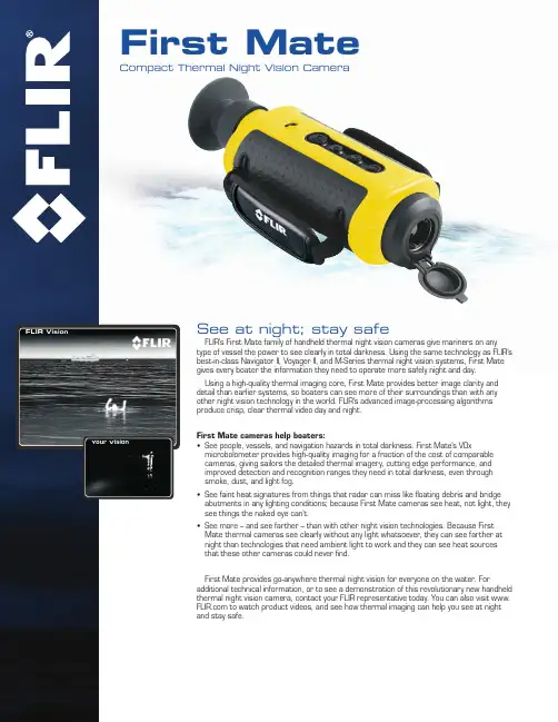
See at night; stay safeFLIR’s First Mate family of handheld thermal night vision cameras give mariners on anytype of vessel the power to see clearly in total darkness. Using the same technology as FLIR’s best-in-class Navigator II, Voyager II, and M-Series thermal night vision systems, First Mate gives every boater the information they need to operate more safely night and day. Using a high-quality thermal imaging core, First Mate provides better image clarity and detail than earlier systems, so boaters can see more of their surroundings than with any other night vision technology in the world. FLIR’s advanced image-processing algorithms produce crisp, clear thermal video day and night.First Mate cameras help boaters:• See people, vessels, and navigation hazards in total darkness. First Mate’s VOxmicrobolometer provides high-quality imaging for a fraction of the cost of comparable cameras, giving sailors the detailed thermal imagery, cutting edge performance, and improved detection and recognition ranges they need in total darkness, even through smoke, dust, and light fog.• See faint heat signatures from things that radar can miss like floating debris and bridge abutments in any lighting conditions; because First Mate cameras see heat, not light, they see things the naked eye can’t.• See more – and see farther – than with other night vision technologies. Because First Mate thermal cameras see clearly without any light whatsoever, they can see farther at night than technologies that need ambient light to work and they can see heat sources that these other cameras could never find.First Mate provides go-anywhere thermal night vision for everyone on the water. Foradditional technical information, or to see a demonstration of this revolutionary new handheld thermal night vision camera, contact your FLIR representative today. You can also visit to watch product videos, and see how thermal imaging can help you see at nightand stay safe.First MateCompact Thermal Night Vision CameraFLIR VisionYour Vision NASDAQ: FLIR SANTA BARBARAFLIR System, Inc.70 Castilian Dr.Goleta, CA 93117USAPH: +1 877.773.3547PH: +1 805.964.9797FX: +1 805.685.2711BOSTONFLIR Systems, Inc.25 Esquire RoadNorth Billerica, MA 01862USAPH: +1 877.773.3547PH: +1 978.901.8000FX: +1 978.901.8885PORTLANDCorporate HeadquartersFLIR Systems, Inc.27700 SW Parkway Ave.Wilsonville, OR 97070USAPH: +1 877.773.3547PH: +1 503.498.3547FX: +1 503.498.3153NETHERLANDSFLIR Systems BVCharles Petitweg 214847 NW Teteringen - BredaThe NetherlandsPH: +31 (0) 765 79 41 94FX: +31 (0) 765 79 41 99†= Actual object detection range performance may vary depending on camera set-up, environmental conditions, user experience, and type of display use.Visit for the most up-to-date specifications.Equipment described herein may require US Government authorization for export purposes. Diversion contrary to US law is prohibited. Specifications are subject to change without notice. ©2010 FLIR Systems, Inc. All rights reserved. 908602。

全息照相的原理英语作文The principle of holographic photography is based on the interference pattern created by the interaction oflight waves. This pattern captures the three-dimensional information of an object, allowing us to reproduce a realistic and detailed image.Holographic photography uses a laser beam to illuminate the object and a photosensitive material to record the interference pattern. The laser light is coherent, meaning that all the light waves have the same frequency and phase, which is essential for creating a clear and sharp hologram.When the laser light reflects off the object, it combines with the reference beam to create an interference pattern on the photosensitive material. This pattern contains information about the object's shape, size, and texture, allowing us to reconstruct a lifelike image when the hologram is illuminated with laser light.Unlike traditional photography, holographic photography captures the complete wavefront of light, preserving both the intensity and phase information. This allows us to reproduce not only the appearance of the object but alsoits depth and spatial relationships, creating a truly realistic representation.One of the key advantages of holographic photography is its ability to capture and display three-dimensional images without the need for special glasses or viewing devices. This makes holograms an ideal tool for scientific research, medical imaging, and artistic expression, opening up new possibilities for visual communication and storytelling.In conclusion, holographic photography offers a unique and powerful way to capture and reproduce three-dimensional images with unparalleled realism and detail. By harnessing the principles of interference and wavefront reconstruction, holograms enable us to experience the world in a new and immersive way, pushing the boundaries of visual representation and storytelling.。

光学效应英语作文The Optical Effect。
Introduction。
The optical effect is a fascinating phenomenon that occurs when light interacts with various materials, resulting in the manipulation of light waves and the creation of stunning visual effects. From the iridescence of a soap bubble to the shimmering colors of a peacock's feathers, the optical effect is all around us, and its beauty and complexity never fail to captivate our imagination.Explanation of the Optical Effect。
The optical effect is a result of the interaction between light and matter. When light waves encounter a material, they can be reflected, refracted, or diffracted, leading to a variety of visual effects. One of the mostcommon optical effects is iridescence, which occurs whenlight waves are scattered by the microstructures on the surface of a material, creating a rainbow-like display of colors. Another well-known optical effect is the shimmering of a mirage, which is caused by the refraction of light asit passes through layers of air with different temperatures. Applications of the Optical Effect。

光学纯对映体英文## Enantiomers and Optical Purity.In the realm of chemistry, chirality refers to the property of a molecule that lacks mirror symmetry, muchlike our left and right hands. Chiral molecules exist in two distinct forms known as enantiomers, which are mirror images of each other but cannot be superimposed. Enantiomers are like two non-identical twins, sharing the same molecular formula and connectivity but differing in their spatial arrangement.Optical purity, a crucial concept in stereochemistry, quantifies the enantiomeric excess of a chiral compound. It measures the proportion of one enantiomer relative to the other in a mixture. A mixture containing equal amounts of both enantiomers is considered racemic and has an optical purity of 0%. Conversely, a mixture containing only one enantiomer is optically pure and has an optical purity of 100%.### Separation of Enantiomers.The separation of enantiomers is a challenging yet essential task in many fields, including pharmaceuticals, agrochemicals, and fragrances. Various techniques can be employed to achieve this, including:Chiral chromatography: This technique utilizes achiral stationary phase that interacts differently with different enantiomers, allowing for their separation.Chiral resolution: This involves converting a racemic mixture into a pair of diastereomers, which can then be separated by conventional methods.Enzymatic resolution: Enzymes, being chiral themselves, can selectively catalyze reactions with one enantiomer over the other, leading to the formation of optically pure products.### Optical Purity Measurement.Optical purity can be determined using various methods, such as:Polarimetry: This technique measures the rotation of plane-polarized light as it passes through a chiral sample. The magnitude and direction of rotation depend on the enantiomeric composition of the sample.NMR spectroscopy: Chiral solvents or chiral shift reagents can be used in NMR spectroscopy to differentiate between enantiomers based on their different chemical shifts.Chromatographic methods: Chiral chromatography or capillary electrophoresis can be used to separate enantiomers and determine their relative abundance.### Significance of Optical Purity.Optical purity is of paramount importance in several areas:Pharmacology: Many drugs are chiral, and their enantiomers can have different pharmacological properties, including efficacy, toxicity, and metabolism. Enantiopure drugs offer advantages in terms of safety and effectiveness.Agrochemicals: Herbicides and pesticides can be chiral, and their enantiomers may differ in their selectivity and environmental impact. Optical purity ensures the targeted control of pests and weeds.Fragrances and flavors: The fragrance and flavor of chiral compounds can depend on their enantiomeric composition. Optical purity control allows for the creation of specific scents and tastes.### Applications of Chiral Compounds.Chiral compounds find widespread applications invarious industries:Pharmaceuticals: Enantiopure drugs include ibuprofen,naproxen, and thalidomide.Agrochemicals: Herbicides such as glyphosate and pesticides like cypermethrin are chiral.Fragrances and flavors: Enantiopure compounds like menthol, camphor, and limonene contribute to thedistinctive scents and tastes of products.Materials science: Chiral polymers, liquid crystals, and self-assembling systems have unique properties and applications in optics, electronics, and nanotechnology.### Conclusion.The concept of enantiomers and optical purity is crucial for understanding the stereochemistry of chiral compounds. The ability to separate and determine the optical purity of enantiomers is essential in numerous fields, including pharmaceuticals, agrochemicals, and fragrances. The significance of optical purity lies in itsimplications for the safety, efficacy, and properties of chiral compounds in various applications.。
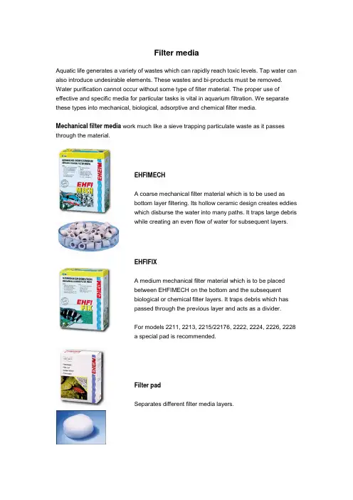
Filter mediaAquatic life generates a variety of wastes which can rapidly reach toxic levels. Tap water can also introduce undesirable elements. These wastes and bi-products must be removed. Water purification cannot occur without some type of filter material. The proper use of effective and specific media for particular tasks is vital in aquarium filtration. We separate these types into mechanical, biological, adsorptive and chemical filter media.Mechanical filter media work much like a sieve trapping particulate waste as it passes through the material.EHFIMECHA coarse mechanical filter material which is to be used as bottom layer filtering. Its hollow ceramic design creates eddies which disburse the water into many paths. It traps large debris while creating an even flow of water for subsequent layers.EHFIFIXA medium mechanical filter material which is to be placed between EHFIMECH on the bottom and the subsequent biological or chemical filter layers. It traps debris which has passed through the previous layer and acts as a divider.For models 2211, 2213, 2215/22176, 2222, 2224, 2226, 2228 a special pad is recommended.Filter padSeparates different filter media layers.EHFISYNTHA completely neutral filter wool. The fine phenol free structureof this synthetic material traps tiny particles of dirt. It should beloosely placed as the last layer in your filter arrangement. Formodels 2222, 2224, 2226, 2228 we recommend a specialEHFISYNTH pad.Biological filtrationA build-up of toxic nitrogenous wastes is a natural result of all aquarium inhabitant's life processes. In nature, the body of water is large enough to dissipate or dilute these wastes. Some will even be converted into usable energy by living organisms. Within an aquarium however, without a powerful biological breakdown of these toxins, the fish literally poison themselves. This is the reason why biological filtration is the most desirable of all aquarium filtration.This type of filtration is the purification of the aquarium water by using living organisms, such as nitrifying bacteria. These desirable bacteria will attach themselves to all hard surfaces within the aquarium system. They use the toxins as a food, converting harmful toxins such as ammonia and nitrite into less harmful nitrate. Nitrate can then be removed by performing regular water changes.After prolonged use, mechanical and chemical filter media will act in a biological manner. They provide some surface area for bacterial colonization but this is actually very limited. In order to provide the greatest amount of surface area for bacteria colonies, filter media such as EHFISUBSTRAT or EHFILAV should be used.EHFISUBSTRATTo create biologically sound water as found in nature, you need EHFISUBSTRAT. Biological filtering is based on a natural decomposition of harmful substances using helpful bacteria. They convert ammonia and nitrite into relatively non-toxic nitrate. The efficiency of biological filtration is limited by the media that bacteria are growing on. With over 450 ml per litre (22, 000sq. ft. per lmp. gal. / 18, 3000 sq. ft. per U.S. gal.) EHFISUBSTRAT is a specially designed sintered glass.Bacteria are able to stick better to a surface which has a complex pore system. EHFISUBSTRAT has been specially developed to offer optimum sites for bacteria colonization. The effectiveness of these bacteria is linked to how much oxygen and toxins can flow by. With faster decomposition of toxins compared to other media. Highly effective, economically priced, it is the best biological media available to aquarium hobbyists.EHFILAVA naturally occuring porous volcanicrock which is ideal for biological filtrationwhere large debris is present such asponds and highly stocked aquariums.This natural product is pre-tested forimpurities before pachaging to ensurethat it is free of toxins.Adsorptive filter mediaAdsorptive filtration is a process in which dissolved substances are captured by solid bodies such as carbon. These dissolved substances can be harmful to aquatic life. They are generally of chemical origin such as chlorine in tap water, alkaline residues of aquarium medication and even some dissolved metals. However the toxic substances accumulate and the absorption capacity of the carbon is limited. With all types of carbon, the effectiveness is limited to a short period of time. They must then be removed from the filter, to avoid having the adsorbed substances washed back into the aquarium. We recommend that carbon be used for short -term only and for a specific purpose. After the inital aquarium setup or to remove medications or additives, turbidity, water discoloration and odor.EHFIAKTIVThis product offers the highest adsorption. It is alkaliactivated, acid-washed, pH neutral, heavy metal free andformed in a special compression mold to perform a rapid,highly effective adsorption of harmful substances andresidues of medication.EHFIKARBONA high quality filter carbon. It is recommended for short-termuse in freshwater aquariums.Chemical filter mediaEHFITORFA specially treated media, whichmakes the water more acidic andlowers the carbon hardness. Thepeat filter is recommedable for softwater fishes in order to achieve atropical aquatic environment. Justlike in the case of all other additivesthe changed water property has tobe regularly monitored.Aquatic life generates a variety of wastes which can rapidly reach toxic levels. Water purification cannot occur without some type of filter material. The proper use of effective and specific media for particular tasks is vital in aquarium filtration. Ideal water conditions very much depend on the correct use of filter media. We separate these types into mechanical, biological, adsorptive and chemical filter media.EHEIM filter pads are used to separate the different layers in standard filters.EHFISYNTH filter pad for mechanical fine cleaning, forthe EHEIM professionel filters series.EHEIM filter cartridges made of special foam materialsprovide a large surface area. They can be changed in afew simple steps and after their "running-in" time theynot only function mechanically but also biologically. Inaddition, there are also active carbon cartridges, whichare ideally suited for adsorption.。
光学英语知识点总结1. Nature of LightLight is a form of electromagnetic radiation that is visible to the human eye. It travels in the form of waves, with a specific wavelength and frequency. It can also be described as a stream of particles called photons. The wave-particle duality of light is a fundamental concept in quantum mechanics, and it has important implications for the behavior of light in different situations.2. Behavior of Light WavesLight waves can exhibit several important phenomena, including reflection, refraction, diffraction, and interference. When a light wave encounters a boundary between two different media, it may be reflected, refracted, or both. The laws of reflection and refraction describe how light waves behave at such boundaries, and they are fundamental to our understanding of optics.Diffraction is the bending of light waves around obstacles or through small openings, which leads to the spreading of light into a pattern of bright and dark regions. Interference is the interaction of multiple light waves, which can lead to the reinforcement or cancellation of the waves, producing a pattern of bright and dark fringes. These phenomena are important in many optical applications, such as the design of lenses, mirrors, and optical instruments.3. Polarization of LightPolarization is another important property of light waves, which describes the orientation of the oscillations of the electric and magnetic fields in the wave. Light waves can be polarized in different ways, including linear, circular, and elliptical polarization. Polarization has important applications in various optical technologies, such as 3D movie glasses, glare-reducing sunglasses, and liquid crystal displays (LCDs).4. Applications of OpticsOptics has many practical applications in various fields, including astronomy, microscopy, photography, telecommunications, and laser technology. In astronomy, telescopes and other optical instruments are used to study the universe and observe distant objects in the sky. In microscopy, optical techniques are used to visualize and analyze tiny structures and particles, such as cells and molecules.In photography, cameras and lenses are used to capture and record images using the principles of optics. In telecommunications, optical fibers are used to transmit and receive data at high speeds over long distances, enabling the internet and other communication networks. Laser technology is another important application of optics, with a wide range of uses in medicine, industry, and research.In conclusion, optics is a fascinating and important branch of physics that studies the behavior and properties of light. It covers a wide range of topics, including the nature of light, the behavior of light waves, and the applications of optics in various fields. Understanding the principles of optics is essential for many technological and scientific advancements, and it continues to be a vibrant and active area of research and innovation.。
静电成像方式英语作文In the realm of technology and imaging, electrostatic imaging has emerged as a pivotal method for creating high-quality images. This essay delves into the principles behind electrostatic imaging, its applications, and the advantages it offers over traditional imaging techniques.Introduction to Electrostatic ImagingElectrostatic imaging is a process that utilizes the principles of electrostatics to create images. It involves the use of static electric charges to attract and adhere toner particles onto a drum or a photoreceptor, which then transfers the image onto paper or other media.Working PrincipleThe process begins with a photoreceptor that is uniformly charged. This photoreceptor is exposed to a light image of the document to be copied. The areas exposed to light lose their charge, creating an electrostatic latent image on the photoreceptor. This image is then developed by applying a charged toner, which adheres to the charged areas of the photoreceptor. The toner image is then transferred to paper, and heat and pressure are applied to fuse the toner to the paper, creating a permanent image.ApplicationsElectrostatic imaging is widely used in various fields. It is the core technology behind laser printers and photocopiers.Additionally, it is employed in digital photography, where digital images are printed onto paper with high fidelity. The medical field also utilizes electrostatic imaging for producing high-resolution X-ray images.Advantages Over Traditional MethodsCompared to traditional methods, electrostatic imaging offers several advantages. It is capable of producing sharp, high-resolution images with a wide range of colors. The process is also more efficient, as it requires less material and energy, leading to lower costs and a smaller environmental footprint. Furthermore, electrostatic imaging allows for faster printing speeds and the ability to print on a variety of media.ConclusionElectrostatic imaging has revolutionized the way we create and reproduce images. Its efficiency, versatility, andquality make it an indispensable technology in today'sdigital age. As advancements continue, electrostatic imaging is poised to play an even more significant role in the future of imaging technology.References1. "Electrostatic Printing: A Comprehensive Guide." Tech Imaging Journal, vol. 12, no. 4, 2020, pp. 45-52.2. "The Evolution of Electrostatic Imaging in the Digital Age." Modern Technology Review, vol. 34, 2019, pp. 78-85.3. "Medical Applications of Electrostatic Imaging." Health Tech Innovations, vol. 21, no. 2, 2021, pp. 32-38.This essay provides a concise overview of electrostaticimaging, highlighting its fundamental principles, applications, and benefits. As the technology continues to evolve, it is expected to further enhance the quality and efficiency of image reproduction across various industries.。
第 22 卷 第 2 期2024 年 2 月太赫兹科学与电子信息学报Journal of Terahertz Science and Electronic Information TechnologyVol.22,No.2Feb.,2024基于CMOS有源超材料的生物分子的自旋太赫兹传感陈亚玄a,c,d,孔茹茹a,李昭颖a,c,d,孙统a,c,d,熊凡a,c,d,孙芸a,d,刘永山a,张有光b,白中扬*b,c,d,温良恭*a,c,d(北京航空航天大学 a.集成电路科学与工程学院;b.电子信息工程学院,北京100191;c.深圳研究院,广东深圳518063;d.杭州创新研究院,浙江杭州310051)摘要:基于互补金属氧化物半导体(CMOS)有源超材料,通过结合自旋太赫兹源,对生物分子的太赫兹频段指纹谱进行传感检测。
对比基于自旋太赫兹源和基于光电导天线的太赫兹时域光谱系统测量的3种不同生物样品的指纹谱特征峰,验证了自旋太赫兹源测量生物样品的可行性。
同时,提出一种基于CMOS有源超材料的生物分子太赫兹传感方案,仿真结果表明CMOS调控器件对生物样品的扫描测试表现为生物透射峰与器件谐振峰变化统一。
当吸收峰位于器件的调控范围内时,随着加电压的增大,生物透射谱谐振频率减小,出现红移,最大红移量达到40 GHz。
因为不同的生物样品有不同的吸收峰,根据不同的太赫兹指纹谱吸收峰的位置设计了5种对应中心频率的CMOS有源超材料,为实现生物分子太赫兹传感系统的小型化和集成化提供了理论及实验基础。
关键词:自旋太赫兹源;指纹谱;CMOS有源超材料;太赫兹传感中图分类号:TN20 文献标志码:A doi:10.11805/TKYDA2022249Spintronic terahertz sensing of biological molecules based on CMOScontrollable metamaterialsCHEN Yaxuan a,c,d,KONG Ruru a,LI Zhaoying a,c,d,SUN Tong a,c,d,XIONG Fan a,c,d,SUN Yun a,d,LIU Yongshan a,ZHANG Youguang b,BAI Zhongyang*b,c,d,WEN Lianggong*a,c,d(a.School of Integrated Circuit Science and Engineering;b.School of Electronic Information Engineering,Beijing 100191,China;c.Shenzhen Innovation Institute,Shenzhen Guangdong 518063,China;d.Hangzhou Innovation Institute,Beihang University,Hangzhou Zhejiang 310051,China)AbstractAbstract::The sensing and detection of the biomolecule Terahertz(THz) spectrum fingerprint is performed based on Complementary Metal Oxide Semiconductor(CMOS) controllable metamaterials,using a Spintronic THz Emitter device. The spintronic THz spectrum fingerprint of three differentbiological samples were benchmarked with results using THz photoconductive antennas. The results showthat the feasibility of measuring biological samples with spin terahertz source is verified. At the sametime, a frequency based biomolecular THz sensing scheme is proposed by utilizing CMOS controllablemetamaterials. Finite element models are built based on the performance test and the biosensing processof the CMOS controllable metamaterial devices. Five CMOS controllable metamaterials were designedwith center frequencies related to the absorption peaks of the biomolecules under test. The simulationresults show that the resonance frequency has a red shift with the increase of voltage, and the maximumred shift is up to 40 GHz. This paper provides experimental and theoretical foundations for buildingminiaturized and integrated biomolecular THz sensing systems.KeywordsKeywords::spin THz source;fingerprint spectra;CMOS controllable metamaterials;THz sensing文章编号:2095-4980(2024)02-0160-08收稿日期:2022-12-28;修回日期:2023-10-09基金项目:广东省基础与应用基础研究基金资助项目(2021B1515120012);青岛市科技惠民示范专项基金资助项目(23-2-8-smjk-3-nsh)*通信作者:白中扬email:*********************.cn;温良恭email:**************.cn;第 2 期陈亚玄等:基于CMOS 有源超材料的生物分子的自旋太赫兹传感太赫兹(THz)技术具有频谱宽、穿透性强、光子能量低、相干性等特点[1]。
Exceptional stability, reliability, and qualityThermal imaging is the right choicefor newspapersTRENDSETTER NEWS Platesetters bring the quality, stability, and repeatability of thermal imaging to newspaper printing. Thermal imaging reduces process variations found in visible light and UV systems that can lead to variable quality, so you are able to improve your margins through efficient plate making and deliver excellent print quality.In addition, thermal imaging allows you to utilize daylight conditions in prepress and is the only technology that enables process free plate making. Thermal imaging is fast too.New MCU increases productivityYou have the flexibility to choose the level of automation that’s right for your business. The new Multi Cassette Unit (MCU) offers automated plate loading and unloading of up to 960 plates, so you can run continuously for longer. The TRENDSETTER NEWS Platesetter is also available with an optional panorama and dual broadsheet plate rotation to position the plate ready to inline punch & bend with a compact footprint.New app for remote monitoringThe new, optional, KODAK Mobile CTP ControlApp lets you monitor your TRENDSETTER NEWS Platesetter remotely with your Android or IOS device. Know instantly if one of your CTP devices needs attention, even if you are out of the room or off site, so you can get back to making plates quickly.Expand your opportunities with SQUARESPOT Imaging TechnologyAll TRENDSETTER NEWS Platesetters useKODAK SQUARESPOT Imaging Technology, so you can produce plates of outstanding quality at an affordable price. Thermal SQUARESPOT Technology delivers consistent dot accuracy and provides tonal stability for repeatable AM screens. The result is higher screen rules, sharper linework, excellent reverse type and legibility, and minimal early dot wear.Reduce your environmental footprintThe KODAK TRENDSETTER NEWS Platesettercan help you maximize quality and productivity while minimizing environmental impact. Its small footprint reduces shipping waste and costs, as well as space requirements, and a new cooling system enables power savings of up to 30%* from its initial design—down to only 770 watts while imaging.The TRENDSETTER NEWS Platesetter also supports SONORA NEWS Process Free Plates, so you can completely eliminate your processor and chemistry.* Compared to the KODAK TRENDSETTER NEWS Series IV PlatesettersKODAKEastman Kodak Company 343 State Street Rochester, NY 14650 USA +1-866-563-2533 in North America. Produced using Kodak Technology. ©Kodak, 2017. Kodak, Generation News, Sonora News, SQUAREspot, Staccato, Trendsetter, Trendsetter News and the Kodak Logo are trademarks of Kodak. Subject to technical change without notice. W.PSD.306.1026.en.11 (K-408)KODAK TRENDSETTER NEWS PLATESETTER 1 Imaging speed and throughput is dependent on media sensitivity. All values are for media sensitivity of 75mJ/cm 2 Productivity may be reduced by job queuing delays, raster file format, raster file manipulations, plate processor transport speed, plate exposure requirements, and plate placement in load bay. 3 Supported plate gauge is 0.20 to 0.30 mm. For more information, please consult your Kodak representative.4 Minimum plate size around drum is 383 mm with the plate rotation option, and minimum plate size for manual bypass is 305 x 215 mm.EN60825-1 and US Federal Regulations 21 CFR 1040.10 - /GO/CTP。
摘要图像识别技术是人类视觉认知的延伸,是人工智能的一个重要领域,随着计算机技术和人工智能技术的发展,图像识别技术越来越成为人工智能的基础技术。
蔬菜图像的识别是当今各农产品市场急需采用的一项人工智能技术。
如何有效的对蔬菜图像进行处理,并提取其特征是蔬菜图像识别技术的核心问题。
本文以蔬菜图像的分割为主线,利用3种方法对分割后的蔬菜图像进行特征提取,并验证其有效性。
首先,蔬菜图像的分割的目的是将蔬菜图像的背景进行去除,仅保留蔬菜图像的前景部分。
为此,需要将蔬菜图像的前景部分与背景部分进行区别。
实验表明,利用K均值聚类算法辅以形态学操作能有效地对蔬菜图像进行分割。
对分割后的蔬菜图像进行特征提取,分别提取颜色一致性矢量(CCVs)、和差直方图矢量(SDH)及边界/内部像素分类(BIC)特征矢量作为图像的特征。
利用提取出的特征矢量,对同种类的蔬菜图像和不同种类的蔬菜图像进行比较,以验证矢量的有效性。
实验证明相似图像之间的矢量距离值较小,相似度较大,因此提取出的特征矢量能做为图像的特征。
关键词:图像分割,图像特征提取,K均值聚类,颜色一致性矢量(CCVs),和差直方图(SDH),边界/内部像素分类(BIC)AbstractImage recognition technology is an extension of the human visual cognition and an important field of artificial intelligence.With the development of computer technology and artificial intelligence technology, image recognition technology has become the basis of artificial intelligence technology.Vegetable image identification as an artificial intelligence technology is an urgent need of today's various markets for agricultural products.How to effectively dealing with the vegetable image processing, and extracting its characteristics is the core issue ofvegetable image recognition technology. Vegetable image segmentation is the main line of this paper and we use three methods for feature extraction, and verify its effectiveness.First of all, the purpose of image segmentation is image background removal, retaining only prospects of the picture.To do this, we need to distinguish the foreground part and background part of the image.Experimental results show that using K-Means clustering algorithm with morphological operation can effectively segment vegetable image.For the image of vegetables after segmentation ,we need to extract their features.In this paper ,we extract color consistency vector (CCVs), difference histogram vector (SDH) and boundary/internal pixels classification feature vectors (BIC) as characteristics of the image. In order to verify the validity of the vector,using the feature vectors to compare different images,both of the same kind of vegetables images and different kinds of vegetables images. Experiments prove that the smaller values of the vector distance between similar images, the bigger similarity is, so the extracted feature vector can as a characteristic of the image.Key words:image segmentation, image feature extraction, K-Means clustering, color consistency vector (CCVs), difference histogram vector (SDH), boundary/internal pixels classification feature vectors (BIC)目录1 绪论 (1)1.1 课题研究的目的与意义.................................................. 1.2 蔬菜识别的发展概况....................................................1.3 机器视觉及模式识别....................................................1.3.1 机器视觉............................................................1.3.2 模式识别............................................................1.4 论文的主要工作........................................................1.5 论文的内容安排........................................................2 蔬菜图像预处理 (5)2.1 图片数据..............................................................2.2 蔬菜图像的简单预处理..................................................2.2.1 图像的灰度化........................................................2.2.2 图像的二值化........................................................2.3 蔬菜图像的分割........................................................2.3.1 具有封闭外层轮廓的蔬菜图像的背景去除算法............................2.3.2 K-Means聚类算法....................................................2.3.3 含阴影图像的分割算法................................................2.4 实验结果与分析........................................................2.5 本章小结..............................................................3 蔬菜图像的特征提取 (18)3.1 颜色特征提取..........................................................3.1.1 颜色一致性特征矢量CCVs.............................................3.2 纹理特征提取..........................................................3.2.1 和差直方图特征矢量SDH..............................................3.3 形状特征提取..........................................................3.3.1 边界/内部像素分类特征矢量BIC.......................................3.4 实验结果与分析........................................................3.5 本章小结..............................................................4 全文总结与展望 .........................................................4.1 全文总结..............................................................4.2 展望.................................................................. 参考文献 .................................................................. 致谢 ......................................................................1 绪论1.1 课题研究的目的与意义智能识别蔬菜是当今各农产品市场及超市急需采用的一项技术。
FEASIBILITY OF LITTORAL IMAGING WITH A3 kHz SYNTHETIC APERTURE SONARStephen Celuzza,1 Philip Abbot,1 Charles Gedney,1Brad Gillespie,2 and Kenneth Rolt21Ocean Acoustical Services and Instrumentation Systems, Inc.5 Militia DriveLexington, MA 02173 USA2Sanders, a Lockheed Martin CompanyAdvanced Systems DirectorateP.O. Box 868Nashua, NH 03061 USAINTRODUCTIONThe feasibility of using a 3 kHz surface ship bow sonar as a synthetic aperture sonar (SAS) for imaging targets in shallow water is presented. The study consists of modelling the environment with a time-varying ocean surface; a downward refracting sound velocity profile; and bottom roughness, penetration and scattering. Targets placed in the model include both a point target to simulate a mine and confirm imaging resolution, and an array of point targets to simulate the length extent of a submarine. The multipath returns were then processed by standard side-scan sonar (SSS) methods and SAS methods. Replica processing (matched filtering) was employed to improve imaging. Useful SAS imaging is shown.LIMITATIONS OF SAS IN SHALLOW WATERIn order to focus an synthetic array, the phase errors between the individual elements cannot exceed λ/8, or about 6 cm at 3 kHz. Thus, during the time period of synthesizing the array, the required phase errors from the combined stability of the ocean and ship motion should be as small as possible, and not exceed λ/8.Spatial and Temporal CoherenceThe variability of the ocean (both in time and in space) causes phase errors to be introduced along a synthetic array. This variability is discussed by Rolt and Abbot.1 Platform MotionNormal ship motion would exceed the tolerances required for synthetic aperture sonar focussing. However, careful monitoring of the ship's attitude and position can compensate for this motion and allow focussing. Several systems, including an Inertial Navigation System (INS), the Global Positioning System (GPS) and Kalman trackers can be used to monitor these factors.While standard GPS (or even differential GPS) would not provide the resolution required for aperture synthesis, advanced GPS techniques would provide adequate resolution. In particular, a method originally developed for land surveying, known as carrier phase tracking, is capable of providing resolutions on the order of 1 mm. This has been adapted for moving platforms into a process called real time kinematic (RTK) processing. Commercially available RTK systems currently provide accuracy on the order of 3 cm. Mounting a few of these receivers in distinct locations on the ship and tying them to a Kalman tracker using a ship dynamics model could provide estimates of the bow sonar position.CHARACTERISTICS OF SITUATION MODELLEDGeometryThe combination source/receiver for this study is a surface ship's hull sonar. The ship is travelling at 5.14 m/s (10 knots) due north in 100 m deep water. This ship transmits a 5 msec ping every 4 sec, or 20.56 m, over a track 2056 m long, for a total of 101 transmit/receive locations.The targets are east of the ship's track, approximately at the same latitude as the 50th transmit location. They consist of 10 point reflectors, arranged to simulate a mine and a submarine. The mine is simulated by a single point reflector at range 2770 m and azimuth 1058 m, while the submarine is simulated by 9 point reflectors at range 2800 m, spaced 6 m apart, from azimuth 1000 m to 1048 m. All targets are 50 m deep.Sonar ParametersThe pings emitted by the hull sonar are modelled as 5 msec linear frequency modulated (LFM) slides, sweeping in frequency from 2,250 Hz to 3,750 Hz, resulting in a center frequency of 3,000 Hz and a 1,500 Hz bandwidth. The vertical beamwidth is ±30°and the azimuthal beamwidth is 90°.Environmental ParametersThe acoustic transmission were modelled by a proprietary ray-based model. A typical downward refracting sound velocity profile was used (sound velocity approximately equal to 1,540 m/s at the surface and 1,500 m/s at the bottom). This resulted in all rayspropagating to the bottom within a few hundred meters, and rays propagating to the targets interacting with the bottom several times.Other model inputs included a time-varying sea surface with waves having a standard deviation of 0.32 m, and a silt-sand bottom with sound velocity 1,700 m/s.SIGNAL PROCESSING TECHNIQUES AND IMAGESSide Scan SonarIn conventional side scan sonar, the received sound pressure levels are stacked, one on top of the other, as in Figure 1. The ping number is related to the azimuthal location by the ping spacing (ping 1 is transmitted at 0 m and received at 20.56 m, while ping 100 is transmitted at 2035.44 m and received at 2056 m). The range is determined from the time delay by an approximated mean sound velocity. The shades of gray in the figure correspond to the magnitude of the received sound pressure level, with black representing the highest pressures and white representing the lowest pressures. (Color graphics illustrate the returns even better.)Note that these images have a highly distorted X-Y scale. We show a total of 100 m in range, but more than 2000 m in azimuth. This is done to avoid large areas of blank space on the plots, and to enhance the appearance of the range migration hyperbolas. Range migration hyperbolas show the characteristic spread of the echo level into the neighboring source locations, as the receiver moves past a fixed target.If this figure was the only information about a particular area, one might conclude that there were at least two distance targets in the area. First, a low strength target with a range near 2,770 m, with a closest point of approach (CPA) near ping 52. A second, stronger target occurs at a range of 2,800 m, with a CPA between pings 49 and 52. In fact, these two echoes correspond to the mine and the submarine, respectively.The other echoes in the figures correspond to multipath propagation of the echoes from the targets. However, without a priori knowledge of the number of targets, these could be mistaken for additional targets. One could suppose that the echoes that occur beyond 2,800 m in range, since they occur at the same azimuthal location, are likely to be due to multipath echoes. A more reliable method of determining this is by using matched-field processing, which attempts to predict the location of multipath echoes. We have had success with this technique, but it is beyond the scope of this paper.The image in Figure 1 is improved upon by replica processing (also called matched filtering), and shown in Figure 2. Replica processing is accomplished by cross correlating the received signal with the transmitted signal. Comparing the two figures shows two improvements: the range resolution is improved (the elevated magnitudes at the mine and the submarine are shorter in the range direction); and the contrast between the targets and the background is improved, as the replica correlation process discriminates against the background noise.Synthetic Aperture SonarTarget images can be further enhanced by focusing the synthetic aperture array. During the focusing process, the replica processed data are shifted in time to correct for the spherical wave fronts as they arrive at the individual elements of the synthesized array. Since we do not know the target's position, the array must be focused differently for each assumed target position.To illustrate this process, we have selected a 150 m by 100 m horizontal box centeredon the submarine and divided it into a grid of 1 m by 1 m cells. Without prior knowledge of the target locations, side scan sonar results must be used to determine the location of the focusing grid. We then selected an array centered on this box and examined the replica processed data for each element of this array. Since the array sources and receivers are located at adjacent locations separated by 20.56 m, the received signal at each element and each instant in time represents a possible target located on an ellipsoidal surface whose foci are located at the source and receiver positions. At each time for which the ellipsoid intersects the focusing grid, the grid function is incremented by the value of the received signal at that time. The focused SAS array output for each grid point is obtained by summing the focused array element outputs over all of the elements in the SAS array.Figures 3 and 4 show the focused array outputs for the 150 m by 100 m box using N=4 and 32 synthetic aperture elements, respectively. Although these figures cover significantly less area and have fewer points than the previous SSS images, we note that the resolution of the mine's position has been enhanced. Further, as the number of elements is increased, the azimuthal resolution is improved. These figures also show a target at the submarine location as well as false targets at larger ranges due to multipath. Aliasing lobes are also apparent in these figures as is expected since the element spacing is much larger than optimal. Note however that the aliasing lobes tend to smear out mostly in azimuth and slightly across range as N is increased.CONCLUSIONSConventional side scan sonar images were shown for a downward refracting shallow water acoustics problem. These images exhibited the range migration hyperbolas which provide a viable way of narrowing the surveillance area in the shallow water environment. They also show multipath hyperbolas, which can be used to correct for platform motion and medium instability, as well as estimate target depth.Synthetic aperture sonar images demonstrate improved resolution over the side scan sonar images, due to the increased length of the array. Thus, we conclude that it may be possible to use surface ship bow sonars to create synthetic aperture sonars, once the limitations of the environment and ship motion compensation are overcome. REFERENCES1. K. Rolt and P. Abbot, Littoral coherence limitations of acoustic arrays, 23rd International Symposium onAcoustical Imaging (1997).Figure 1. Side Scan Sonar Image with White Noise. The Echo from the Mine can be seen at Range = 2,770 m, and the echo from the submarine can be seen at Range = 2,800 m. Echoes beyond 2,800 m are due to multipath propagation.Figure 2. Side Scan Sonar Image with White Noise, Replica Correlated. Note that, compared to Figure 1, the range resolution has improved and the signal-to-noise ratio has increased.Figure 3. Synthetic Aperture Sonar Image, Focussed with N=4 Elements, Replica Correlated. Notice that the Range-Migration Hyperbolas have been Removed. The Mine is Visible at Range = 2,770 m, Azimuth = 1,058 m, and the Submarine is Visible at Range = 2,800 m, Azimuth = 1,000 m to 1,048 m.Figure 4. Synthetic Aperture Sonar Image, Focussed with N=32 Elements, Replica Correlated. Compared to Figure 3, the Azimuthal Resolution has been Improved, and the Azimuthal Aliases Reduced.。