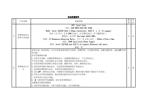
HW_U2B4 教师版
- 格式:doc
- 大小:88.00 KB
- 文档页数:8

Taurus SeriesMultimedia PlayersTB4Specifications Doc u ment V ersion:V1.3.2Doc u ment Number:NS120100359Copyright © 2018 Xi'an NovaStar Tech Co., Ltd. All Rights Reserved.No part of this document may be copied, reproduced, extracted or transmitted in any form or by any means without the prior written consent of Xi’an NovaStar Tech Co., Ltd.Trademarkis a trademark of Xi’an NovaStar Tech Co., Ltd.Statementi Table of ContentsTable of ContentsTable of Contents ............................................................................................................................ ii 1 Overview .. (1)1.1 Introduction (1)1.2 Application (2)You are welcome to use the product of Xi’an NovaStar Tech Co., Ltd. (hereinafter referred to as NovaStar). This document is intended to help you understand and use the product. For accuracy and reliability, NovaStar may make improvements and/or changes to this document at any time and without notice. If you experience any problems in use or have any suggestions, please contact us via contact info given in document. We will do our best to solve any issues, as well as evaluate and implement any suggestions.2 Features (3)2.1 Synchronization mechanism for multi-screen playing (3)2.2 Powerful Processing Capability (3)2.3 Omnidirectional Control Plan (3)2.4 Synchronous and Asynchronous Dual-Mode (4)2.5 Wi-Fi AP Connection (4)3 Hardware Structure (6)3.1 Appearance (6)3.1.1 Front Panel (6)3.1.2 Rear Panel ................................................................................................................................................73.2 Dimensions (8)4 Software Structure (9)4.1 System Software (9)4.2 Related Configuration Software (9)5 Product Specifications ................................................................................................................ 106 Audio and Video Decoder Specifications (11)6.1 Image (11)6.1.1 Decoder (11)6.1.2 Encoder (11)6.2 Audio (12)6.2.1 Decoder (12)6.2.2 Encoder (12)6.3 Video (13)6.3.1 Decoder (13)6.3.2 Encoder (14)iiaurus Series Multimedia PlayersTB4 Specifications 1 Overview1 Overview 1.1 IntroductionTaurus series products are NovaStar's second generation of multimedia playersdedicated to small and medium-sized full-color LED displays.FeaturesThe TB4 of the Taurus series products (hereinafter referred to as “TB4”) has thefollowing features:●Synchronization mechanism for multi-screen playing●Powerful processing capability●Omnidirectional control plan●Synchronous and asynchronous dual-mode●Wi-Fi AP connection Note:If the user has a high demand on synchronization, the time synchronization module isrecommended. For details, please consult our technical staff.In addition to solution publishing and screen control via PC, mobile phones and LAN,the omnidirectional control plan also supports remote centralized publishing andmonitoring.Other Hardware FeaturesThe hardware of the TB4 also has the following features:●Loading capacity up to 1300,000 pixels, with the maximum width of 4096 pixelsand maximum height of 1920 pixels●Wired Gigabit Ethernet●Stereo audio output●HDMI Loop●HDMI input and auto full-screen display●Manual and scheduled switching between synchronous and asynchronousmodes.●USB drive importing display●Onboard light sensor connector allowing for automatic and scheduled brightnessadjustment1 Overview 1.2 ApplicationTaurus series products can be widely used in LED commercial display field, such asbar screen, chain store screen, advertising machine, mirror screen, retail storescreen, door head screen, on board screen and the screen requiring no PC.Classification of Taurus’ application cases is shown in Table 1-1. Table1-1 Application●●multiple screens.Independent screen: U s e a PC or the client software of amobile phone to enable single-p oint connection andmanagement of a screen.Cluster screen: Use the cluster solution developed byNovaStar to realize centralized management and monitor ofWired connection: A PC connects to Taurus through theWi-Fi connection: PC, Pad and mobile phone can connect to Taunusthrough Wi-Fi, which can be enabled in the case without PC in conjunctionwith ViPlex software.●Ethernet cable o r LAN.●aurus Series Multimedia PlayersTB4 Specifications2 Features 2.1 Synchronization mechanism for multi-screen playingThe TB4 support switching on/off function of synchronous display.When synchronous display is enabled, the same content can be played on differentdisplays synchronously if the time of different TB4 units are synchronous with oneanother and the same solution is being played.2.2 Powerful Processing CapabilityThe TB4 features powerful hardware processing capability:● 1.5 GHz eight-core processor●Support for H.265 4K high-definition video hardware decoding playback●Support for 1080P video hardware decoding● 2 GB operating memory●8 GB on-board internal storage space with 4 GB available for users2.3 Omnidirectional Control Plan●More efficient: Use the cloud service mode to process services through a uniformplatform. For example, VNNOX is used to edit and publish solutions, andNovaiCare is used to centrally monitor display status.●More reliable: Ensure the reliability based on active and standby disasterrecovery mechanism and data backup mechanism of the server.●More safe: Ensure the system safety through channel encryption, data fingerprintand permission management.●Easier to use: VNNOX and NovaiCare can be accessed through Web. As long asthere is internet, operation can be performed anytime and anywhere.●More effective: This mode is more suitable for the commercial mode ofadvertising industry and digital signage industry, and makes informationspreading more effective.2.4 Synchronous and Asynchronous Dual-ModeThe TB4 supports synchronous and asynchronous dual-mode, allowing moreapplication cases and being user-friendly.When internal video source is applied, the TB4 is in asynchronous mode; when HDMI-input video source is used, the TB4 is in synchronous mode. Content can be scaledand displayed to fit the screen size automatically in synchronous mode.Users can manually and timely switch between synchronous and asynchronousmodes, as well as set HDMI priority.2.5 Wi-Fi AP ConnectionThe TB4 has permanent Wi-Fi AP. The SSID is "AP + the last 8 digits of the SN", forexample, "AP10000033", and the default password is "". The TB4 requires no wiringand users can manage the displays at any time by connecting to the TB4 via mobilephone, Pad or PC.aurus Series Multimedia PlayersTB4 Specifications aurus Series Multimedia Players TB4 SpecificationsTB4 ’s Wi -F i AP signal strength is related to the transmit distance and environment. Users can change the Wi-Fi antenna as required.3Hardware Structure3.1 Appearance3.1.1 Front PanelNameDescriptionPWR Power status indicatorAlways on: Power input is normal.System status indicator● Flashing once every other 2 seconds: The system is operating normally.● Flashing once every other second: The system is installing the upgrade package.● Flashing once every other 0.5 second: The system isdownloading data from the Internet or copying the upgrade package.● Always on/off: The system is operating abnormally. CLOUDInternet connection status indicator● Always on: The unit is connected to the Internet and the connection status is normal.● Flashing once every other 2 seconds: The unit isconnected to VNNOX and the connection status is normal. RUNFPGA status indicatorSame as the signal indicator status of the sending card: FPGA is operating normally.SYSFigure 3-1 Front panel of the TB4Note: All product pictures shown in this document are for illustration purpose only. Actual product may vary.Table 3-1 Description of TB4 front panelT urus Series Multimedia PlayersTB4 SpecificationsNameDescriptionSWITCHButton for switching between synchronous and asynchronous modes● Always on: Synchronous mode●Off: Asynchronous modeFigure 3-2 Rear panel of the TB4aurus Series Multimedia PlayersTB4 SpecificationsName DescriptionTEMP Temperature sensor port LIGHT Light sensor port WiFi-AP Wi-Fi AP antenna port COM1 Reserved COM2 ReservedGigabit Ethernet port Indicator status:●Yellow indicator always on: The unit is connected to 100M Ethernet cable and the status is normal. ●Green and yellow indicators always on at the same time: The unit is connected to Gigabit Ethernet cable and the status is normal.USB USB 2.0 portHDMI ● IN: HDMI 1.4 input ●OUT: HDMI 1.4 outputAUDIO OUT Audio outputRESET Factory reset buttonPress and hold the button for 5 seconds to reset the unit to factory settings. LED OUTOutput Ethernet portETHERNETNote: All product pictures shown in this document are for illustration purpose only. Actual product may vary.Table 3-2 Description of TB4 rear panelName DescriptionON/OFF Power switch100-240V~,50/60Hz Power inputUnit: mm4 Software Structure4 Software Structure4.1 System Software●Android operating system software●Android terminal application software●FPGA programNote: The third-party applications are not supported.4.2 Related Configuration SoftwareTable 4-1 Related configuration softwareNovaLCT5 Product Specifications 5 Product Specifications8 GB on-board with 4 GBavailable0°C–50°CListDimensionsAntennafor usersPackinginformationmensions (H×W×D)6Audio and Video Decoder6.1.2 EncoderTypeCodecSupported Image SizeMaximum Data RateRemarks6Type Codec Supported Image SizeContainer RemarksJPEGJFIF1.02JPG, JPEGNot SupportNon-interleaved Scan Software support SRGB JPEGSoftware support Adobe RGB JPEGBMP BMP No Restriction BMP N/A GIF GIF No Restriction GIF N/A PNG PNG No Restriction PNG N/A WEBPWEBPNo RestrictionWEBPN/A4 8 × 48 p ixels~8176 × 8176 pixel sSpecifications6.1 Image6.1.1 Decoder6.2 AudioOGG, OGA8KHZ~48AMR-NB 2HZ~ 48 16 6.3 VideoH.264.6.3.2 EncoderMOV, 3GPM bps。

诺瓦科技LED多媒体播放器TB4规格书多媒体播放器TB4规格书文档版本:V1.3.2文档编号:NS120000358版权所有 © 西安诺瓦电子科技有限公司 2018。
保留一切权利。
非经本公司书面许可,任何单位和个人不得擅自摘抄、复制本文档内容的部分或全部,并不得以任何形式传播。
i目录商标声明是诺瓦科技的注册商标。
声明欢迎您选用西安诺瓦电子科技有限公司(以下简称诺瓦科技)的产品,如果本文档为您了解和使用产品带 来帮助和便利,我们深感欣慰。
我们在编写文档时力求精确可靠,随时可能对内容进行修改或变更,恕不 另行通知。
如果您在使用中遇到任何问题,或者有好的建议,请按照文档提供的联系方式联系我们。
对您 在使用中遇到的问题,我们会尽力给予支持,对您提出的建议,我们衷心感谢并会尽快评估采纳。
目录目录 ..................................................................................................................................................... ii 1 概述 (1)1.1产品简介 (1)1.2应用场景 (2)2 产品特点 (3)2.1支持多屏播放同步机制 (3)2.2处理性能强大 (3)2.3全方位控制方案 (3)2.4支持同步异步双模式 (4)2.5支持WiFi AP 连接 (4)3 硬件结构 (6)3.1外观图 (6)3.1.1前面板 (6)3.1.2后面板 (7)3.2尺寸图 (8)4 软件结构 (9)4.1系统软件 (9)4.2相关配置软件 (9)5 产品规格 ........................................................................................................................................ 106 音视频解码规格. (11)6.1图片 (11)6.1.1解码器 (11)6.1.2编码器 (11)6.2音频 (12)6.2.1解码器 (12)6.2.2编码器 (12)6.3视频 (13)6.3.1解码器 (13)6.3.2编码器 (14)iiTaurus 系列多媒体播放器TB4 规格书1 概述1概述1.1产品简介Taurus系列产品为诺瓦科技针对中小型LED全彩显示屏推出的第二代多媒体播放器。

软件更新第 4 代 操作系统安装时间:在无现有数据的情况下,大约需要 20 分钟。
安装时间取决于现有数据的大小及显示屏上现有的软件版本。
下列第 4 代显示器可通过无线方式或使用 U 盘和“约翰迪尔软件管理器”下载并安装最新软件包,可访问 ,在“软件更新”页获取软件包。
如果在第 4 代显示器上使用“在线显示器软件更新”,则通过无线方式下载软件的时间长短因蜂窝信号覆盖强度或无线互联网连接强度而异。
如需更多帮助,请参考“下载指南”。
通过无线方式重新编程 -https://youtu.be/XSG7O3_9KGI?list=PL1KGsSJ4CWk4fhvFOaBZz261XGwPfXvqk注:第 4 代操作系统软件更新将自动安装相应的第 4 代操作系统帮助文件。
一项更新无法与另一项更新分开。
机器应用软件更新机器应用软件位于第 4 代显示器菜单上的“机器设置”中。
机器应用软件更新需要由约翰迪尔经销商使用 Service ADVISOR™ 安装。
发布说明内容新功能和改进通用信息培训软件包版本第 4 代 操作系统10.16.1400-91第 4 代 操作系统帮助文件10.4.63-10AMS 应用程序10.16.1400-91新功能和改进屏幕操作手册 -• 在显示器上的“帮助中心”应用程序中,新增了第4 代显示器的《操作手册》。
这部分内容将根据将来软件的更新需要而继续更新。
补充的屏幕帮助内容,可从“帮助中心”获得。
注:操作前,请认真阅读最新的《操作手册》。
如需最新版手册,请与经销商联系或访问。
导航 -• 驾驶员现在能在导航应用程序中创建“直线轨迹”和 “AB 曲线”的复制轨迹。
“复制轨迹”用来复制当前处于激活状态的导航轨迹。
新的复制轨迹的名称默认为是原始轨迹的名称加上(1)。
例如,轨迹“West”的复制轨迹的默认名称为 “West(1)”。
选择轨迹名称输入框修改轨迹名称。
新轨迹可以在机器上居中,或者向左或向右变换位置。
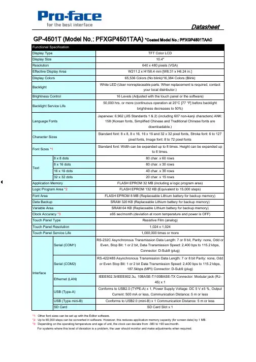
40h 30Text Language Fonts 16 Levels (Adjusted with the touch panel or the software)Brightness Control Display Type Display Size Resolution Effective Display Area Backlight Service Life 8 x 8 dots 8 x 16 dots 1616d t 80 char. x 60 rows 80 char. x 30 rows Display Colors Backlight 640 x 480 pixels (VGA)W211.2 x H158.4 mm [W8.31 x H6.24 in.]65,536 Colors (No blink)/16,384 Colors (Blink)White LED (User nonreplaceable parts. When replacement is required, contact your local distributor.)TFT Color LCD 10.4"50,000 hrs. or more (continuous operation at 25°C [77 °F] before backlight brightness decreases to 50%)Japanese: 6,962 (JIS Standards 1 & 2) (including 607 non-kanji characters) ANK:158 (Korean fonts, Simplified Chinese and Traditional Chinese fonts are downloadable.)Character Sizes Standard font: 8 x 8, 8 x 16, 16 x 16 and 32 x 32 pixel fonts, Stroke font: 6 to 127pixel fonts, Image font: 8 to 72 pixel fonts Font Sizes *1Standard font: Width can be expanded up to 8 times. Height can be expanded up to 8 times.GP-4501T (Model No.: PFXGP4501TAA) *Coated Model No.: PFXGP4501TAAC *3: Depending on the operating temperature and age of unit, the clock can deviate from -380 to +90 sec/month.For systems where this level of deviation is a problem, the user should monitor and make adjustments when required.Conforms to USB2.0 (mini-B) x 1 Communication Distance: 5 m or lessSD Card Slot x 140 char. x 30 rows *1: Other font sizes can be set up with the Editor software.*2: Up to 60,000 steps can be converted in software. However, this reduces application memory capacity (for screen data) by 1 MB.Clock Accuracy *3RS-232C Asynchronous Transmission Data Length: 7 or 8 bit, Parity: none, Odd orEven, Stop Bit: 1 or 2 bit, Data Transmission Speed: 2,400 bps to 115.2 kbps,Connector: D-Sub9 (plug)IEEE802.3i/IEEE802.3u, 10BASE-T/100BASE-TX Connector: Modular jack (RJ-45) x 1RS-422/485 Asynchronous Transmission Data Length: 7 or 8 bit Parity: none, Oddor Even Stop Bit: 1 or 2 bit Data Transmission Speed: 2,400 bps to 115.2 kbps,187.5kbps (MPI) Connector: D-Sub9 (plug)20 char. x 15 rows±65 sec/month (deviation at room temperature and power is OFF)SRAM 64 KB (Replaceable Lithium battery for backup memory)Resistive Film (analog)1,024 x 1,0241,000,000 times or more16 x 16 dots 32 x 32 dots Variable Area Conforms to USB2.0 (TYPE-A) x 1, Power Supply Voltage: DC 5 V ±5 %, OutputCurrent: 500 mA or less, Communication Distance: 5 m or lessInterfaceTouch Panel Resolution Touch Panel Type Touch Panel Service Life USB (Type mini-B)SD Card Ethernet (LAN)Serial (COM1)USB (Type-A)Serial (COM2)Data Backup SRAM 320 KB (Replaceable Lithium battery for backup memory)Application Memory FLASH EPROM 32 MB (including a logic program area)Logic Program Area *2FLASH EPROM 132 KB (Equivalent to 15,000 steps)Font Area FLASH EPROM 8 MB (Replaceable Lithium battery for backup memory)Pollution Degree Atmosphere Voltage Endurance Storage Humidity International Safety Standards-20 to 60 °C [-4 to 140 °F]Allowable Voltage Drop In-Rush Current Surrounding Air Temperature Power Consumption 0 to 55 °C [32 to 131 °F]Storage Temperature Rated Input Voltage AC 100 to 240 V Insulation Resistance AC 85 to 264 V 1 cycle or less(Voltage drop interval must be 1 second or more.)30 A or less Input Voltage Limits 100 Vac: 44 VA or less 240 Vac: 58 VA or less DC 500 V, 10 MΩ or more (between charging and FG terminals)AC 1,500 V, 20 mA for 1 min (between charging and FG terminals)10 to 90 % RH (Wet bulb temperature: 39 °C [102.2 °F] or less - no condensation.)IEC/EN61131-2 compliant 147 m/s², X, Y, Z directions for 3 times Vibration Resistance Air Pressure (altitude range)800 to 1,114 hPa (2,000 m above sea level or less)0.1 mg/m³ (10-7 oz/ft³) or less (non-conductive levels)For use in Pollution Degree 2 environment Ambient Humidity Dust Free of corrosive gases IEC/EN61131-2 compliant, 5 to 9 Hz Single amplitude 3.5 mm [0.14 in.], 9 to 150Hz Fixed acceleration: 9.8 m/s², X, Y, Z directions for 10 cycles (approx. 100 min)Concussion Resistance *1:*2:External Dimensions Panel Cut Dimensions *2W259 x H201 mm [W10.2 x H7.91 in.], Panel thickness area: 1.6 to 5 mm [0.06 to0.2 in.]2 kg [4.4 lb] or less (display unit only)Contact Discharge Method: 6 kV (IEC/EN61000-4-2 Level 3)W272.5 x H214.5 x D57 mm [W10.73 x H8.44 x D2.24 in.]Cooling Method Weight Approx.Grounding Functional grounding: Grounding resistance of 100Ω, 2mm² (AWG 14) or thicker wire, or your country's applicable standard. (Same for FG and SG terminals)Structure *1Natural air circulationNoise Voltage: 1,500 Vp-p, Pulse Duration: 1 µs, Rise Time: 1 ns (via noisesimulator)Noise Immunity IP65f NEMA #250 TYPE 4X/13 (on the front panel when properly installed in anenclosure)Electrostatic Discharge Immunity The front face of the GP unit, installed in a solid panel, has been tested using conditions equivalent to the standards shown in thespecification. Even though the GP unit's level of resistance is equivalent to these standards, oils that should have no effect on the GP can possibly harm the unit. This can occur in areas where either vaporized oils are present, or where low viscosity cutting oils are allowed to adhere to the unit for long periods of time. If the GP's front face protection sheet becomes peeled off, these conditions can lead to the ingress of oil into the GP and separate protection measures are suggested. Also, if non-approved oils are present, it may causedeformation or corrosion of the front panel's plastic cover. Therefore, prior to installing the GP unit, be sure to confirm the type of conditions that will be present in the GP's operating environment. If the installation gasket is used for a long period of time, or if the unit and its gasket http://www pro face com/product/hmi/gp4000html Pro face's GP4000Series website Regarding dimensional tolerance, everything +1/-0 mm [+0.04/-0 in.] and R in angle are below R3 [R0.12 in.]./product/hmi/gp4000.html Pro-face's GP4000 Series website Copyright (C) 2011 Digital Electronics Corporation. All rights reserved. Specifications may change without notice.2012.1 Rev.1。

V2416A SeriesCompact,fanless,vibration-proof computers for rolling stock applicationsFeatures and Benefits•Intel Celeron/Core i7processor•Two hot-swappable2.5-inch HDD or SSD storage expansion trays•Dual independent DVI-I displays•2Gigabit Ethernet ports with M12X-coded connectors•2CFast sockets for OS backup•M12A-coded power connector•Compliant with EN50121-4•Complies with all EN50155mandatory test items1•IEC61373certified for shock and vibration resistance•Ready-to-run Debian7,Windows Embedded Standard7,and Windows10Embedded IoT Enterprise2016LTSB platforms•-40to70°C wide-temperature models available•Supports SNMP-based system configuration,control,and monitoring(Windows only)CertificationsIntroductionThe V2416A Series embedded computers are based on the Intel3rd Gen processor and feature4RS-232/422/485serial ports,dual LAN ports,and 3USB2.0hosts.In addition,the V2416A computers provide dual DVI-I outputs and comply with the mandatory test items of the EN50155 standard,making them suitable for a variety of industrial applications.The CFast socket,SATA connectors,and USB sockets provide the V2416A computers with the reliability needed for industrial applications that require data buffering and storage expansion.Most importantly,the V2416A computers come with2hot-swappable storage trays for inserting additional storage media,such as hard disk or solid-state drives,and support hot swapping for convenient,fast,and easy storage replacement. Each storage tray has its own LED to indicate whether or not a storage module is plugged in.The V2416A Series computers come preinstalled with a choice of Linux Debian7or Windows Embedded Standard7to provide programmers with a familiar environment in which to develop sophisticated,bug-free application software at a low cost.1.This product is suitable for rolling stock railway applications,as defined by the EN50155standard.For a more detailed statement,click here:/doc/specs/EN_50155_Compliance.pdfAppearanceFront View Rear ViewSpecificationsComputerCPU V2416A-C2Series:Intel®Celeron®Processor1047UE(2M cache,1.40GHz)V2416A-C7Series:Intel®Core™i7-3517UE Processor(4M cache,up to2.80GHz) System Chipset Mobile Intel®HM65Express ChipsetGraphics Controller Intel®HD Graphics4000(integrated)System Memory Pre-installed4GB DDR3System Memory Slot SODIMM DDR3/DDR3L slot x1Supported OS Linux Debian7Windows Embedded Standard7(WS7E)32-bitWindows Embedded Standard7(WS7E)64-bitStorage Slot CFast slot x2Computer InterfaceEthernet Ports Auto-sensing10/100/1000Mbps ports(M12X-coded)x2Serial Ports RS-232/422/485ports x4,software selectable(DB9male)USB2.0USB2.0hosts x1,M12D-coded connectorUSB2.0hosts x2,type-A connectorsAudio Input/Output Line in x1,Line out x1,M12D-codedDigital Input DIs x6Digital Output DOs x2Video Input DVI-I x2,29-pin DVI-D connectors(female)Digital InputsIsolation3k VDCConnector Screw-fastened Euroblock terminalDry Contact On:short to GNDOff:openI/O Mode DISensor Type Dry contactWet Contact(NPN or PNP)Wet Contact(DI to COM)On:10to30VDCOff:0to3VDCDigital OutputsConnector Screw-fastened Euroblock terminalCurrent Rating200mA per channelI/O Type SinkVoltage24to40VDCLED IndicatorsSystem Power x1Storage x1Hot-swappable2LAN2per port(10/100/1000Mbps)Serial2per port(Tx,Rx)Serial InterfaceBaudrate50bps to921.6kbpsFlow Control RTS/CTS,XON/XOFF,ADDC®(automatic data direction control)for RS-485,RTSToggle(RS-232only)Isolation N/AParity None,Even,Odd,Space,MarkData Bits5,6,7,8Stop Bits1,1.5,2Serial SignalsRS-232TxD,RxD,RTS,CTS,DTR,DSR,DCD,GNDRS-422Tx+,Tx-,Rx+,Rx-,GNDRS-485-2w Data+,Data-,GNDRS-485-4w Tx+,Tx-,Rx+,Rx-,GNDPower ParametersInput Voltage12to48VDCPower Connector M12A-coded male connectorPower Consumption(Max.) 3.3A@12VDC0.82A@48VDCPower Consumption40W(max.)Physical CharacteristicsHousing AluminumIP Rating IP30Dimensions(with ears)250x86x154mm(9.84x3.38x6.06in)Dimensions(without ears)275x92x154mm(10.83x3.62x6.06in)Weight4,000g(8.98lb)Installation DIN-rail mounting(optional),Wall mounting(standard) Protection-CT models:PCB conformal coating Environmental LimitsOperating Temperature Standard Models:-25to55°C(-13to131°F)Wide Temp.Models:-40to70°C(-40to158°F) Storage Temperature(package included)-40to85°C(-40to185°F)Ambient Relative Humidity5to95%(non-condensing)Standards and CertificationsEMC EN55032/24EMI CISPR32,FCC Part15B Class AEMS IEC61000-4-2ESD:Contact:6kV;Air:8kVIEC61000-4-3RS:80MHz to1GHz:20V/mIEC61000-4-4EFT:Power:2kV;Signal:2kVIEC61000-4-5Surge:Power:2kVIEC61000-4-6CS:10VIEC61000-4-8PFMFRailway EN50121-4,IEC60571Railway Fire Protection EN45545-2Safety EN60950-1,IEC60950-1Shock IEC60068-2-27,IEC61373,EN50155Vibration IEC60068-2-64,IEC61373,EN50155DeclarationGreen Product RoHS,CRoHS,WEEEMTBFTime332,173hrsStandards Telcordia(Bellcore),GBWarrantyWarranty Period3yearsDetails See /warrantyPackage ContentsDevice1x V2416A Series computerInstallation Kit8x screw,for storage installation2x storage key1x wall-mounting kit8x washer,for HDD/SSDDocumentation1x document and software CD1x quick installation guide1x warranty cardDimensionsOrdering InformationModel Name CPU Memory(Default)OS CFast(CTO)Backup CFast(CTO)Hot-SwappableSSD/HDD Tray(CTO)Operating Temp.ConformalCoatingV2416A-C2Celeron1047UE4GB or optional1(Optional)1(Optional)2(Optional)-25to55°C–V2416A-C2-T Celeron1047UE4GB or optional1(Optional)1(Optional)2(Optional)-40to70°C–V2416A-C2-CT-T Celeron1047UE4GB or optional1(Optional)1(Optional)2(Optional)-40to70°C✓V2416A-C7i7-3517UE4GB or optional1(Optional)1(Optional)2(Optional)-25to55°C–V2416A-C7-T i7-3517UE4GB or optional1(Optional)1(Optional)2(Optional)-40to70°C–V2416A-C7-CT-T i7-3517UE4GB or optional1(Optional)1(Optional)2(Optional)-40to70°C✓V2416A-C2-W7E Celeron1047UE4GB8GB1(Optional)2(Optional)-25to55°C–V2416A-C2-T-W7E Celeron1047UE4GB8GB1(Optional)2(Optional)-40to70°C–V2416A-C7-T-W7E Core i7-3517UE4GB8GB1(Optional)2(Optional)-40to70°C–Accessories(sold separately)Battery KitsRTC Battery Kit Lithium battery with built-in connectorCablesCBL-M12XMM8PRJ45-BK-100-IP67M12-to-RJ45Cat-5E UTP gigabit Ethernet cable,8-pin X-coded male connector,IP67,1mCBL-M12(FF5P)/Open-100IP67A-coded M12-to-5-pin power cable,IP67-rated5-pin female M12connector,1mConnectorsM12A-5PMM-IP685-pin male circular threaded D-coded M12USB connector,IP68M12X-8PMM-IP678-pin male X-coded circular threaded gigabit Ethernet connector,IP67M12A-5P-IP68A-coded screw-in sensor connector,female,IP68,4.05cmM12A-8PMM-IP678-pin male circular threaded A-codes M12connector,IP67-rated(for field-installation)Power AdaptersPWR-24270-DT-S1Power adapter,input voltage90to264VAC,output voltage24V with2.5A DC loadPower CordsPWC-C7AU-2B-183Power cord with Australian(AU)plug,2.5A/250V,1.83mPWC-C7CN-2B-183Power cord with two-prong China(CN)plug,1.83mPWC-C7EU-2B-183Power cord with Continental Europe(EU)plug,2.5A/250V,1.83mPWC-C7UK-2B-183Power cord with United Kingdom(UK)plug,2.5A/250V,1.83mPWC-C7US-2B-183Power cord with United States(US)plug,10A/125V,1.83mAntennasANT-WDB-ANF-0407 2.4/5GHz,omni-directional antenna,4/7dBi,N-type(male)Wall-Mounting KitsV2400Isolated Wall Mount Kit Wall-mounting kit with isolation protection,2wall-mounting brackets,4screwsDIN-Rail Mounting KitsDK-DC50131DIN-rail mounting kit,6screws©Moxa Inc.All rights reserved.Updated Jun12,2019.This document and any portion thereof may not be reproduced or used in any manner whatsoever without the express written permission of Moxa Inc.Product specifications subject to change without notice.Visit our website for the most up-to-date product information.。

第四章DPU图形组态软件1.概述DPU在线组态软件主要完成对DPU或VDPU的在线组态、调试、组态文件保存的任务。
软件可对一个组态文件进行离线组态,并保存到磁盘上。
可读入磁盘上的组态文件下装到DPU。
可上装DPU中的组态,再保存到磁盘上。
可在图形组态界面上直接对DPU进行修改、操作、调试、观察趋势曲线等。
组态界面附合IEC-1131-3中功能块图形组态的标准。
DPU组态软件必须在已有点目录基础上进行工作。
因为点目录定义了所有DPU上网点的集合,而DPU组态软件仅用于定义某一个DPU的I/O和算法,即控制策略。
在定义DPU于其它DPU的关系是,必须依靠点目录来统一上下网点的标识。
因此,在开始在线DPU组态前,必须生成好所需的全局点目录。
方法见“全局点目录(实时数据库)的组态说明”。
2.启动组态软件在启动组态软件之前,必需先启动XDPS总控软件Netwin.exe。
然后,在Netwin中以ENG以上身分登录,就可安“DPU组态”按钮启动DpuCfg.exe。
或用其它Windows方法执行DpuCfg.exe。
启动之后,屏幕上出现如下窗口:启动后,可以看到软件外观从上到下依次分标题条、菜单条、窗口客户区、状态条。
窗口客户区分二个区域,左边为文件、DPU、页的列表区;右边为页或DPU属性的编辑区。
许多菜单命令同时也放在工具条中,另外,对DPU、页、功能块按属标由键,也可弹出相关的菜单命令,但以下叙述只以菜单命令为主。
状态条主要显示菜单命令的详细提示。
启动组态软件时,全局点目录或数据库已由Netwin装入。
组态过程对任何全局点的引用,必须已存在于点目录中。
本组态软件,不包含对全局点目录的组态和修改功能。
DPU下拉菜单中分三个菜单命令区,上面一区用于在线组态,操作的是DPU或VDPU 对象;中间一区用于离线组态,操作的是组态文件;下边是打印命令。
3.打开组态文件,进入离线组态启动后任何时候,可选DPU菜单中的“新文件”或“打开文件”打开DPU组态文件。

T I W I-U B2EM B OARDUser GuideLast updatedMay 28th, 2013Table of Contents1Introduction (3)1.1Purpose & Scope (3)1.2Applicable Documents (3)1.3Revision History (3)2TiWi-uB2 Module Description (4)3TiWi-uB2 EM Board Hardware (5)3.1Antenna (5)3.2Connectors (5)3.3Required Signals between EM Board and Host Device (6)3.4Connecting EM Board to Host Platform (7)3.5Power Supply (7)3.6Serial Interfaces (7)3.7HCI UART (8)3.8PCM Interface (8)3.9Option 1: Using EM Connectors (8)3.10Option 2: Using Single Row Headers (11)3.11Using J7 with USB to Serial Converter (12)4Schematic (13)4.1Bill Of Material (BOM) (14)5Application Development (15)5.1Overview (15)5.2Development Tools (15)6Contacting LS Research (20)1Introduction1.1 Purpose & ScopeThe purpose of this document is to provide details regarding the setup and use of theTiWi-uB2 module on an EM board. This document covers a description of the EM board and its features and a brief tutorial on how to operate the module EM board.1.2 Applicable Documents∙TiWi-uB2 Datasheet (330-0100)∙TiWi-uB2 Antenna Design Guide (330-0106)1.3 Revision HistoryTable 1 Revision History2TiWi-uB2 Module DescriptionThe TiWi-uB2 EM “Evaluation Module” Board is an evaluation platform for the LSResearch TiWi-uB2 Bluetooth and Bluetooth Low Energy (BLE) module.Communication between the TiWi-uB2 module, which is a slave, and the host device is through a UART interface.The TiWi-uB2 EM Board contains an on board chip antenna and U.FL connector. The EM board is intended for evaluation purposes when used in conjunction with variousTexas Instruments MSP430 and Stellaris development boards.Figure 1 TiWi-uB2 EM Board TopFigure 2 TiWi-uB2 EM Board Bottom3 TiWi-uB2 EM Board Hardware 3.1 AntennaThe TiWi-uB2 EM Board contains an on board chip antenna which is modular certified for FCC 15.247 and IC RSS-210, as well as compliant to the RF requirements for ETSI EN 300 328 and ETSI EN 301 489. The antenna layout and circuitry on the EM Board can be replicated on a custom designed PCB assembly. Assuming the design/layout is followed exactly as that which is on the EM Board, the custom PCB will retain the modular certification. Below are details on the certifications.FCC ID: TFB-BT1, 15.247 IC ID: 5969A-BT1, RSS 2103.2 ConnectorsThere are two primary connectors on the TiWi-uB2 EM Board (J1 & J2). These provide a standard interface to Texas Instruments development platforms (See Section 3.9). Two additional non populated connectors (J4 & J5) provide access to all of the significant signals on the module on a standard, single row 2mm pitch header.165423789Figure 3 TiWi-uB2 EM Board Top Side ConnectorsTable 2 TiWi-uB2 EM Board Top Side Connectors3.3 Required Signals between EM Board and Host DeviceIn addition to power and ground, there are three signals required for connecting a TiWi-uB2 module to a host device. See Table 3 below for details on these connections.Table 3 TiWi-uB2 Required Connections3.4 Connecting EM Board to Host PlatformThe TiWi-uB2 EM Board is intended to allow for evaluation of and early developmentwith a TiWi-uB2 module. The EM Board has two “EM” connectors on the bottom of the board that allows for easy connection to various Texas Instruments microcontrollerdevelopment platforms. The primary development platform is the MSP430F5438Experimenter Board.It is also possible to adapt the TiWi-uB2 EM Board to work with microcontroller platforms that do not have support for the EM connectors. Sections 3.9 and 3.10 describe the two options for adapting an EM Board to work with other microcontroller platforms.3.5 Power Supply3.5.1 VBATVBAT requires a 3.0V to 4.8V DC power supply.3.5.2 VDD_IOVDD_IO requires a 1.8V DC power supply.Figure 4 Power Supply3.6 Serial InterfacesThere are two serial interfaces to the module, HCI UART and PCM. Each interface isdescribed below.Figure 5 Serial Interfaces3.7 HCI UARTThis is the main interface between the host microcontroller and the module. TheBluetooth UART may also be used to download external patches from the host to theTiWi-uB2. The UART interface supports baud rates from 9600bps to 4Mbps.BT debug pin: The debug interface (TX_DBG) helps customers to debug the HW/SWissues for their application (not pictured).3.8 PCM InterfaceThe PCM Interface can connect to linear PCM Codec devices in master or slave mode.In master mode, the TiWi-uB2 generates the PCM_CLK and PCM_SYNC signals, and in slave mode, these signals are provided by another master on the PCM interface and are inputs to the TiWi-uB2.Figure 6 PCM Interface3.9 Option 1: Using EM ConnectorsEither build a PCB which has the EM Board mating connectors which will allow forplugging the TiWi-uB2 EM Board into, or solder wires to EM Board mating connectorsthat can then be wired into whatever development platform is being used.Below are two suggestions for the mating EM connectors.Through hole connector: Samtec TFM-110-01-S-D-WTSurface Mount connector: Samtec SFM-110-02-L-D-AIf building a PCB that has the mating EM Board connectors, the connectors need to be lined up and spaced 1.2” apart as shown in Figure 7.Figure 7 Host PCB EM Mating Connector Arrangement (Top View)Refer to Table 4 and Table 5 below for details on the signals brought out to the EM connectors J1 and J2.Table 4 EM Connector J1Table 5 EM Connector J2DI = Digital Input; DO = Digital Output; DIO = Digital Input/Output; PI = Power Input3.10 Option 2: Using Single Row HeadersSolder single row 12 pin 2mm headers into locations J4 and J5 on the EM Board, and then build a wiring harness between the headers on the EM Board and themicrocontroller development platform of interest.Below is a suggestion for the 12 pin 2mm headers.Sullins NRPN121PAEN-RCRefer to Table 6 and Table 7 below for details on the signals brought out to the single row headers J4 and J5.Table 6 Single Row Header J4DI = Digital Input; DO = Digital Output; PI = Power InputTable 7 Single Row Header J5DI = Digital Input; DO = Digital Output; DIO = Digital Input/Output; PI = Power Input3.11 Using J7 with USB to Serial ConverterJ7 is provided for interfacing the TiWi-uB2 Module to a USB-to-Serial converter, or similar serial device capable of providing 1.8V logic level data.Table 8 Single Row Header J7DI = Digital Input; DO = Digital Output; DIO = Digital Input/Output; PI = Power Input;4.1 Bill Of Material (BOM)Table 9 TiWi-uB2 EM Board BOM5Application Development5.1 OverviewThe TiWi-uB2 EM Board used in conjunction with a Bluetooth stack running on TI’sMSP430BT5438 or Stellaris LM3S9B96microcontroller (MCU) will reduce designbarriers and provides a highly flexible platform to enable customer’s early prototyping capabilities of embedded Bluetooth applications. The ready-to-go wireless platforms simplify the development process of pre-integrated and pre-validated Bluetooth serial link on an MSP430BT5438 or LM3S9B96system.For an overview of development platforms and software examples see CC256xBluetooth.5.2 Development Tools5.2.1 MSP430 HardwareHardware required for initial evaluation and development include:∙ 2 - TiWi-uB2 EM Boards∙ 1 - TI MSP430 USB Debugging Interface∙ 2 - TI MSP430F5438 Experimenter Boards5.2.2 Stellaris Hardware∙ 1 - TiWi-uB2 EM Board∙ 1 - TI MSP430 USB Debugging Interface∙ 1 - TI Stellaris LM3S9B96 EM2 Expansion Board∙ 1 - TI DK-LM3S9D965.2.3 SoftwareSoftware required for initial evaluation and development include:Stellaris∙Bluetopia®+LE SDK∙CC256x_Bluetopia_Stack∙Stellaris DK-LM3S9B96 SDKIntegrated BT Profiles∙Classic Bluetooth∙SPP∙A2DPFigure 9 TiWi-uB2 EM Board with Stellaris DK-LM3S9B96MSP430Bluetopia∙Bluetopia®+LE SDK∙CC256x_Bluetopia_Stack∙CC256x MSP430 Bluetopia Basic Demo APPSIntegrated BT Profiles∙Classic Bluetooth∙SPP∙Bluetooth Low Energy∙GATT∙ANP∙HRP∙HTP∙PASPThis Bluetooth software solution is licensed from Stonestreet One. The Bluetopia®+LE SDK is comprised of Single Mode and Dual Mode offering implementing the Bluetooth 4.0 specification. Bluetopia®+LE stack is built upon the solid foundation of the Bluetopia protocol stack that is currently being used in millions of consumer and industrial devices and that was first qualified in 2000 `TiWi-uB2 + MSP430 Bluetopia Basic Demo APPS allows users to evaluate TI's CC256x Bluetooth device by using the TiWi-uB2 EM board and the MSP-EXP430F5438 board. The CC256x+MSP430 Bluetooth sample applications code are provided to enable a rich out-of-box experience to the user. The application allows the user to use a console to send Bluetooth commands, setup a Bluetooth Device to accept connections, connect to a remote Bluetooth device and communicate over Bluetooth.Figure 10 TiWi-uB2 EM Board with MSP430F5438 Experimenter Board6Contacting LS ResearchHeadquarters LS Research, LLCW66 N220 Commerce CourtCedarburg, WI 53012-2636USATel: 1(262) 375-4400Fax: 1(262) 375-4248Website Wiki /products-wikiTechnical Support /products-forumSales Contact*************The information in this document is provided in connection with LS Research (hereafter referred to as “LSR”) products. No license, express or implied, by estoppel or otherwise, to any intellectual property right is granted by this document or in connection with the sale of LSR products. EXCEPT AS SET FORTH IN LSR’S TERMS AND CONDITIONS OF SALE LOCATED ON LSR’S WEB SITE, LSR ASSUMES NO LIABILITY WHATSOEVER AND DISCLAIMS ANY EXPRESS, IMPLIED OR STATUTORY WARRANTY RELATING TO ITS PRODUCTS INCLUDING, BUT NOT LIMITED TO, THE IMPLIED WARRANTY OF MERCHANTABILITY, FITNESS FOR A PARTICULAR PURPOSE, OR NON-INFRINGEMENT. IN NO EVENT SHALL LSR BE LIABLE FOR ANY DIRECT, INDIRECT, CONSEQUENTIAL, PUNITIVE, SPECIAL OR INCIDENTAL DAMAGES (INCLUDING, WITHOUT LIMITATION, DAMAGES FOR LOSS OF PROFITS, BUSINESS INTERRUPTION, OR LOSS OF INFORMATION) ARISING OUT OF THE USE OR INABILITY TO USE THIS DOCUMENT, EVEN IF LSR HAS BEEN ADVISED OF THE POSSIBILITY OF SUCH DAMAGES. LSR makes no representations or warranties with respect to the accuracy or completeness of the contents of this document and reserves the right to make changes to specifications and product descriptions at any time without notice. LSR does not make any commitment to update the information contained herein. Unless specifically provided otherwise, LSR products are not suitable for, and shall not be used in, automotive applications. LSR’s products are not intended, authorized, or warranted for use as components in applications intended to support or sustain life.Mouser ElectronicsAuthorized DistributorClick to View Pricing, Inventory, Delivery & Lifecycle Information:L S Research:450-0105。
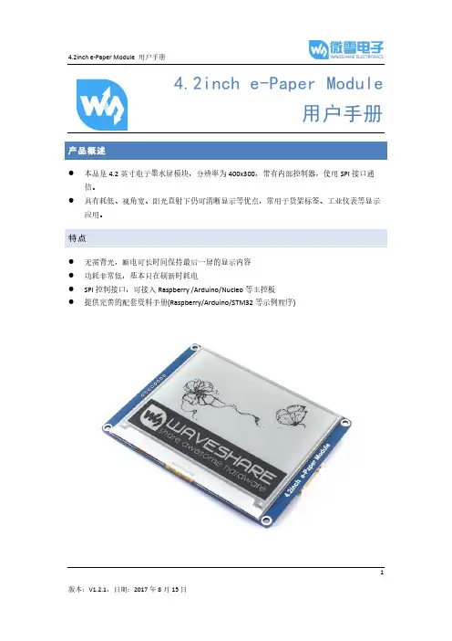
1产品概述●本品是4.2英寸电子墨水屏模块,分辨率为400x300,带有内部控制器,使用SPI 接口通信。
●具有耗低、视角宽、阳光直射下仍可清晰显示等优点,常用于货架标签、工业仪表等显示应用。
特点● 无需背光,断电可长时间保持最后一屏的显示内容 ● 功耗非常低,基本只在刷新时耗电● SPI 控制接口,可接入Raspberry /Arduino/Nucleo 等主控板 ●提供完善的配套资料手册(Raspberry/Arduino/STM32等示例程序)产品参数工作电压: 3.3V通信接口:3-wire SPI、4-wire SPI外形尺寸:90.1mm × 77.0mm × 1.18mm显示尺寸:84.8mm × 63.6mm点距:0.212 × 0.212分辨率:400 × 300显示颜色:黑、白灰度等级: 2刷新功耗:26.4mW(typ.)待机功耗:<0.017mW可视角度:>170°接口说明VCC: 3.3VGND:GNDDIN:SPI通信MOSI引脚CLK:SPI通信SCK引脚CS:SPI片选引脚(低电平有效)DC:数据/命令控制引脚(高电平表示数据,低电平表示命令)RST:外部复位引脚(低电平复位)BUSY:忙状态输出引脚(低电平表示忙)23工作原理 器件介绍本产品使用的电子纸采用“微胶囊电泳显示”技术进行图像显示,其基本原理是悬浮在液体中的带电纳米粒子受到电场作用而产生迁移。
电子纸显示屏是靠反射环境光来显示图案的,不需要背光,即使是在阳光底下,电子纸显示屏依然清晰可视,可视角度几乎达到了180°。
因此,电子纸显示屏非常适合阅读。
通信协议CS 用于从机片选。
仅当CS 为低电平时,模块才会工作。
DC 用于模块的数据/命令控制。
当DC 为低电平时,接收到的数据会被当做指令执行。
SCLK 用于SPI 通信时钟。
U ni c o r e C o n f i dINSTALLATION AND OPERATIONUSER MANUALData subject to change without notice.Communications, Inc.Copyright© 2009-2021, Unicore RTK Positioning ModuleAll-constellation All-frequency GPS/BDS/GLONASS/Galileo U M 4B0DisclaimerInformation in this document is subject to change without notice and does not represent a commitment on the part of Unicore Communications, Inc. No part of this manual may be reproduced or transmitted in any form or by any means, electronic or mechanical, including photocopying and recording, for any purpose without the express written permission of a duly authorized representative of Unicore Communications, Inc. The information contained within this manual is believed to be true and correct at the time of publication.© Copyright 2009-2021 Unicore Communications, Inc. All rights RSV.UM4B0 User Manual ForewordThis <User Manual> offers you information in the features of the hardware, the installation, specification and use of UNICORECOMM UM4B0 product.This manual is a generic version. Please refer to the appropriate part of the manual according to your purchased product configuration, concerning CORS, RTK and Heading.Readers it applies toThis <User Manual> is applied to the technicists who know GNSS Receiver to some extent but not to the general readers.Contents1INTRODUCTION (1)1.1O VERVIEW (1)1.2K EY F EATURES (1)1.3T ECHNICAL S PECIFICATIONS (2)1.4I NTERFACES (2)2HARDWARE (3)2.1D IMENSIONS (3)2.2P IN D EFINITION (T OP V IEW) (4)2.3E LECTRICAL S PECIFICATIONS (6)2.4O PERATIONAL C ONDITIONS (7)2.5P HYSICAL S PECIFICATIONS (7)3HARDWARE DESIGN (8)3.1D ESIGN IN C ONSIDERATIONS (8)3.2UM4B0R EFERENCE D ESIGN (9)3.3P INS (10)3.4PCB P ACKAGING (11)3.5R ESET S IGNAL (12)3.6A NTENNA (12)3.7E XTERNAL A NTENNA F EED D ESIGN (12)4INSTALLATION AND CONFIGURATION (14)4.1ESD H ANDLING P RECAUTIONS (14)4.2H ARDWARE I NSTALLATION (14)4.3S TART U P (17)4.4C ONFIGURATION AND O UTPUT (17)4.4.1Operation Procedures (18)5CONFIGURATION COMMANDS (19)5.1RTK R EFERENCE S TATION C ONFIGURATION (20)5.2RTK R OVER C ONFIGURATION (21)5.3M OVING B ASE C ONFIGURATIONS (21)5.4H EADING C ONFIGURATION (21)6ANTENNA DETECTION (22)7FIRMWARE UPGRADE (22)8PRODUCTION REQUIREMENT (24)9PACKAGING (25)1Introduction1.1OverviewUM4B0 is a high precision positioning and heading RTK module developed by Unicore Communications, targeting light robots, UAVs, intelligent vehicles, GIS information collection, etc.By employing a single UC4C0 (432 channel tracking) baseband chip and a single RF chip, using single-sided SMD packaging, UM4B0 has achieved the smallest size(30x40mm) in this industry with high accuracy heading and positioning output. It can simultaneously track BDS B1I/B2I/B3I/B1C/B2a + GPS L1/L2/L5 + GLONASSL1/L2+Galileo E1/E5a/E5b.Figure 1-1 UM4B0 Module1.2Key Features•30*40mm, the smallest multi-system multi-frequency high precision module •Support GPS L1/L2/L5+GLONASS L1/L2+BDS B1I/B2I/B3I/B1C/B2a+Galileo E1/E5a/E5b•Based on 432 channel NebulasII GNSS SoC•20Hz update rate•Instant RTK initialization and long-distance RTK•Enhanced multi-system multi-frequency RTK technology, JamShield adaptive narrow-band anti-interference and U-AutoAlign multi-path mitigation •Support odometer input and external high-performance IMU interface* •SMD packagingUM4B0 User Manual 1.3Technical SpecificationsTable 1-1 Performance SpecificationsTable 1-2 Functional Ports1.4InterfacesFigure 1-2 Block Diagram1.RF PartThe receiver gets filtered and enhanced GNSS signal from the antenna via a coaxial cable. The RF part converts the RF input signals into the IF signal, and converts IF analog signal into digital signals required for NebulasII (UC4C0) digital processing.2.NebulasII SoC (UC4C0)The UM4B0 incorporates the processing from the NebulasII (UC4C0), UNICORECOMM’s new generation high precision GNSS SoC with 55nm low power design, which supports up to 12 digital intermediate frequency or 8 analog intermediate frequency signals and can track 12 navigation signals with 432 channels.3.1PPSUM4B0 outputs 1 PPS with adjustable pulse width and polarity.4.EventUM4B0 provides 1 Event Mark Input with adjustable pulse width and polarity.2Hardware2.1DimensionsUM4B0 User ManualFigure 2-1 Mechanical Dimensions2.2Pin Definition (Top View)Figure 2-2 UM4B0 Pin DiagramTable 2-2 Pin DefinitionUM4B0 User Manual2.3Electrical SpecificationsTable 2-3 Absolute Maximum Ratings2.4Operational ConditionsTable 2-4 Operational ConditionsNOTE: Since the product contains capacitors at the input, inrush current will occur during power-on. Evaluate in the actual environment in order to check the effect of the supply voltage drop due to the inrush current.2.5Physical SpecificationsTable 2-5 Physical Specifications3Hardware Design3.1Design in ConsiderationsTo make UM4B0 work properly, you need to properly connect the following:The module VCC power-on behavior is repeatable, the initial level is lower than0.4V, and the undershoot and ringing should be guaranteed to be within 5% VCC Provide stable power to the VCC pinConnect all the GND pins to groundConnect VBAT pin to a 3.0V power supplyConnect ANT_IN signal to the antenna, and ensure the 50-ohm impedance matchingConnect ANT_PWR to +3.3~5.5 V voltage, then supply +3.3~5.5 V feed to the antenna through ANT_INEnsure COM1 is connected to a PC or an external processor, and users can use this serial port to receive position data. COM1 is also necessary for firmwareupgradesProperly connect the module’s reset pin FRESET_N to ensure complete reset of the module. It will restore the module to the manufacturing configuration.When ANT_NLOD, ANT_FFLG and antenna detection indication signal are connected, the IO without any pull-up/down of the client MCU terminal isrequired at the input.In order to obtain proper performance, special concerns should be paid during the design:Power supply: A table and low ripple power supply is necessary for good performance. Make sure the peak-to-peak voltage ripple does not exceed50mVpp. It is recommended to use a power chip with current output capacity greater than 2A to power the board.-Use LDO to ensure the purity of power supply-Try to place LDO close to the module in layout-Widen the tracks of power circuit or use copper pour surface to transmit current-Avoid walking through any high-power or high inductance devices such as a magnetic coilInterfaces: Ensure that the signals and baud rate of the main equipment match those of the UM4B0 moduleAntenna interface: Make sure the antenna impedance matches, and the cable is short without any kinks, try to avoid all acute anglesTry to avoid designing in any circuits underneath UM4B0This module is a temperature sensitive device, so dramatic changes in temperature will result in reduced performance. Keep it away as far as possible from any high-power high-temperature air and heating devices3.2UM4B0 Reference DesignFigure 3-1 Minimum Reference DesignFigure 3-2 UM4B0 Reference Design 3.3PinsTable 3-1 Pin Notes3.4 PCB PackagingFigure 3-3 UM4B0 recommended PCB Packaging (unit: mil, in brackets: mm)3.5Reset SignalUM4B0 module can’t work properly unless it is correctly reset after power on. To ensure effective reset, the reset pin (RST) and power supply pin (VCC) must meet the following time sequence requirement. To reset UM4B0 during normal operation, please pull RST pin to low level for more than 5ms.Figure 3-4 UM4B0 RST3.6AntennaThe module has the antenna input pin ANT_IN, which provides a +3.3V antenna feed. When an active antenna of +3.3~5V is adopted, please make sure the 50 Ω antenna impedance is matched.Figure 3-5 UM4B0 Active Antenna Connection3.7External Antenna Feed DesignUM4B0 feeds the antenna signals to the required circuits internally, but in order to effectively prevent damage from lightning and surges, circuit protection should be installed externally to protect the module.High voltage and high-power protection chips should be used to feed the antenna from the outside of the module. A gas discharge tube, varistor, TVS tube and other high-power protective devices may also be used in the antenna circuit to effectively improve the prevention against lightning stroke and surge.ANTFigure 3-6 UM4B0 External Antenna Feed Reference CircuitRemarks:a)L1, feed inductor, 68nH RF inductor in 0603 package is recommended;b)C1, decoupling capacitor, it is recommended to connect two capacitors of 100nF/100pFin parallel;c)C2, DC blocking capacitor, recommended 100pF capacitor.4Installation and Configuration4.1ESD Handling PrecautionsUM4B0 Module is an Electrostatic Sensitive Device (ESD) and special precautions when handling are required.Electrostatic discharge may cause damages to the device. All operations mentioned in this chapter should be carried out on an antistatic workbench, wearing an antistatic wrist strap and using a conductive foam pad. If anantistatic workbench is not available, wear an antistatic wrist strap and connect the other end to a metal frame to avoid the effects of static electricity.Hold the edge of the module, not in direct contact with the componentsPlease check carefully whether the module has obviously loose or damaged components.Figure 4-1 Typical Installation of UM4B0Please check the contents of the package carefully after receiving the package of UM4B0.UM4B0 EVK suite (or evaluation board)User manualUPrecise softwareQualified antennaMMCX antenna cablePC or Laptop with serial ports (Win7 or above), with UPrecise installed4.2Hardware InstallationAfter the above preparation, please follow the steps below to install:Step 1: Make sure to take all the anti-static measures, such as wearing an anti-static wrist strap, grounding the workbench;Step 2: Align UM4B0 transfer board positioning holes and pins with EVK, and fix it in the EVK. EVK provides power supply and standard communication interface for the module to communicate with peripheral devices;NOTE: The RF connector of the board is MMCX, and the suitable connecting wire should be selected according to the package. The input signal gain at the antenna interface is optimal between 20 and 36 dB. Please select the appropriate antenna, antenna cable and online LNA accordingly.Figure 4-2 Installation InstructionStep 3: Select the GNSS antenna with appropriate gain, and fix it in a stable, non-block area, using the coaxial radio frequency cable to connect the antenna to UM4B0 EVK;Step 4: Connect the PC to the EVK serial port through direct serial cable;Figure 4-3 Connect the Serial PortStep 5: Connect a 12V adapter to the EVK power input, and switch on to powerthe device;Figure 4-4 Connect the AntennaStep 6: Open the UPrecise software on the PC;Step 7: Control the receiver through UPrecise to send commands or to log data.4.3Start UpThe power supply for UM4B0 is 3.3VDC. Before powering on the device, please connect UM4B0 serial port to the GNSS antenna. The receiver is started and the communication is connected after powering up. Testing tools are provided for module testing.4.4Configuration and OutputUNICORECOMM UPrecise software provides a user-friendly graphical interface to control and display the operation of your receiver. The features of Uprecise include: Logging Control View: Graphic interface for data loggingConsole window for sending command to the receiver (Console View)Displaying the receiver’s output in ASCII-format (ASCII View)Graphic window for displaying Position of satellite, PRN, and Signal/Noise Ratio (Constellation View)Historical and present Trajectory of the receiver (Trajectory View)Position/Velocity/Time of the receiver (PVT View)Apart from the basic functions above, UPrecise offers advanced functions as follows: Selecting and recording the logSending commands to the receiverOperating and configuration of the ASCII viewThe trajectory view for displaying the present point and the past point of the receiverSwitching Views over the tracking windowSwitching between Constellation ViewsResetting the receiverReplaying the GGA logFigure 4-5 UPrecise SoftwareUM4B0 User Manual 4.4.1Operation ProceduresStep 1. Follow 4.2 Installation Guide to connect the power source, antenna to the board, and turn on the EVK switchStep 2. Click file - > connect the serial port, and set the baud rate; the default baud rate of UB4B0M is 115200bpsFigure 4-6 Connect the Serial PortStep 3. Click the receiver settings button to configure the NMEA message output. Itis recommended to configure GPGGA, GPGSV, and other messages.Figure 4-7 NMEA Data OutputStep 4. Click the receiver settings button to configure the NMEA message output, then click send. It is recommended to configure GPGGA, GPGSV, and other messages. Step 5.In the data session window, click “Send all Message” to complete all the NMEA message output (update rate 1Hz). Right click in the data session window to adjust: output log font size, stop / resume log output, or clear log content, etc.Step 6. Use various views of UPrecise to configure or input commands as required.5Configuration CommandsUM4B0 supports abbreviated ASCII format. Simplified ASCII format without check bit is more accessible to user commands. All commands are composed of a log heading and configuration parameters (If parameters are null, there will be only one heading in the command). Header field contains the command name or message headers. UM4B0 is simple to use, and common instructions are shown in the following table:UM4B0 User Manual5.1RTK Reference Station ConfigurationIf the precise coordinates are known, the precise coordinates could be set as in this example:Mode base 40.07898324818 116.23660197714 60.4265 // set lat lon heightrtcm1033 com2 10 // RTCM1033 input from com2rtcm1006 com2 10rtcm1074 com2 1rtcm1084 com2 1rtcm1094 com2 1rtcm1124 com2 1saveconfigIf precise coordinates are unknown:Mode base time 60 1.5 2.0 // 60 seconds position averagertcm1033 com2 10rtcm1006 com2 10rtcm1074 com2 1rtcm1084 com2 1rtcm1094 com2 1rtcm1124 com2 1saveconfig5.2RTK Rover ConfigurationRTK Rover stations (rover station) receive differential correction data sent from reference stations and receive satellite signals to provide an RTK positioning solution and realize RTK high-precision positioning with cm or mm-level accuracy. Common instructions for configuring RTK rover are as follows:gngga 1saveconfig5.3Moving Base ConfigurationsRTK reference station provides precisely known coordinates of a fixed station. Unlike the RTK reference station, moving base station is in motion, at the same time receives the satellite information, and sends it to the rover station receiver (to be determined) directly or after processing. The rover station receiver receives satellite observations as well as information from the moving base station, to make relative positioning and determine the position of the rover station. Commonly used instructions to set the moving base station are as follows:Mode movingbasertcm1006 com2 1rtcm1074 com2 1rtcm1084 com2 1rtcm1094 com2 1rtcm1124 com2 1saveconfig5.4Heading ConfigurationGNSS heading refers to the clockwise angle between true North and the baseline vector constituted by the two GNSS antennas. Commonly used instructions are as follows:Mode headinggphdt com1 1saveconfigUM4B0 User Manual6Antenna Detection1The UM4B0 module offers antenna open/short detection. The corresponding pins are ANT_NLOAD and ANT_FFLG.•The current monitoring chip outputs 2 bit high and low voltage; the software portion sets 2 bit IO of corresponding NII as input pull-up, and then queries the status of 2 bit IO to check the antenna state.•If ANT_PWR malfunctions, the query result is invalid.•If the antenna is not fed by ANT_PWR but by other means, the query result is invalid.7Firmware UpgradeUprecise software is used for the remote update of UM4B0. Please follow the steps below to upgrade the device:Figure 7-1 Update InterfaceClick “…” to browse the firmware update package, and click“Start” to start the firmware upgrading process (uncheck software reset):1 Optional by FirmwareFigure 7-2 Update StepsWaiting for the process to complete 100% (the upgrade time is normally within 5min):Figure 7-3 Update StepsPlease use COM1 only to update firmware.UM4B0 User Manual8Production RequirementRecommended thermal cycle curve is as follows:Figure 8-1 Soldering TemperatureTemperature rising stage∙Rising slope: Max. 3℃/s∙Rising temperature range:50℃-150℃Preheating stage∙Preheating time: 60 – 120 s∙Preheating temperature range: 150 - 180℃Reflux Stage∙Over melting temperature (217℃) time: 40 – 60 s∙Peak temperature: no higher than 245℃Cooling Stage∙Cooling slope: Max. 4℃ / sNotes:In order to prevent fall off during soldering of the modules, please avoid soldering the module in the back of the Board during design, that is, better not to go through soldering cycle twice.The setting of temperature depends on many factors, such as type of Board, solder paste type, solder paste thickness, etc. Please also refer to the relevant IPC standards and indicators for solder paste.Since the lead soldering temperatures are relatively low, if using this soldering method, please give priority to other components on the Board.9PackagingUM4B0 modules are delivered in trays, which is suitable for mainstream SMT equipment. Each box contains 5 trays, so there are 150 UM4B0 modules in the box. Table 9-1 Package Informationw 。
Installation InstructionsArmorBlock LP24 Sinking Input / 4 Output Module(Cat. No. 1792D-4BT4LP)This ArmorBlock LP2™ I/O module (Cat. No. 1792D-4BT4LP) is a stand-alone 24V dc I/O product which communicates via a DeviceNet network. The sealed housing of this module requires no enclosure.This module has 4 sinking inputs and 4 sourcing outputs accessed through Y splitter cables. Four self-protected 24V dc outputs can provide up to 300mA each.Package ContentsYour package contains:• 1 ArmorBlock LP2 Module •Installation Instructions416222 4 Sinking Input / 4 Output ModuleEuropean Union Directive ComplianceIf this product has the CE mark it is approved for installation within the European Union and EEA regions. It has been designed and tested to meet the following directives.EMC DirectiveThis product is tested to meet Council Directive 89/336/EEC Electromagnetic Compatibility (EMC) and the following standards, in whole or in part, documented in a technical construction file:•EN 50081-2 EMC - Generic Emission Standard, Part 2 - Industrial Environment•EN 50082-2 EMC - Generic Immunity Standard, Part 2 - Industrial EnvironmentThis product is intended for use in an industrial environment.Low Voltage DirectiveThis product is tested to meet Council Directive 73/23/EEC Low V oltage, by applying the safety requirements of EN 61131-2 Programmable Controllers, Part 2 - Equipment Requirements and Tests.For specific information required by EN 61131-2, see the appropriate sections in this publication, as well as the following Allen-Bradley publications:•Industrial Automation Wiring and Grounding Guidelines For Noise Immunity, publication 1770-4.1•Automation Systems Catalog, publication B111Install Your ArmorBlock LP2 I/O ModuleTo install the module:•Set the node address and baud rate.•Mount the module.•Connect the unit to the DeviceNet trunk and the auxilary power source.•Connect the cord sets.Set the Node AddressSet the node address using RSNetworx for DeviceNet software, DeviceNetManager™ software, or another software configuration tool. The module is equipped with AutoBaud detect. AutoBaud lets the module read the settings already in use on your DeviceNet network and automatically adjusts to follow those settings.4 Sinking Input / 4 Output Module3Install the Module1.Attach the module using the dimensions shown below.2.Connect the grey DeviceNet cable to the DeviceNet trunk. Use the1485P-P1R5-MN5R1 T-Part tap to connect to round media. Use the 1485P-P1E4-R5 to connect to the Kwik Link flat media system. Connect the Input / Output Cord Sets to the LP2 ModuleThis module uses 5 pin micro (12mm) style PCB mounted connectors. Four micro caps cover the connectors on your module. Remove the caps and connect your cord sets to the appropriate ports. This product has two inputs or outputs per I/O connector. Use a “Y” splitter cable for access to all I/O connections. For more information on these cables, see the Product Data guide publication 1792-2.1.Use the micro caps to cover and seal unused ports. Pinout diagrams for the connectors are shown next.Input Micro-Connector(View into Sockets)Pin 1 Sensor Source VoltagePin 2 Input BPin 3 Return Logic Ground1Pin 4 Input APin 5 Not UsedOutput Micro-Connector(View into Sockets)Pin 1 Not UsedPin 2 Output BPin 3 Auxilary Power GroundPin 4 Output APin 5 Not UsedLogic Ground is approximately 0.4V above DeviceNet V-measured at the module.414524 4 Sinking Input / 4 Output ModuleOutput Power and DeviceNet CablesRefer to the DeviceNet Cable Planning and Installation Manual for more information on output power and DeviceNet cables for your application.!ATTENTION:•Make sure to connect the proper color coded cables together. DeviceNet cable should connect to DeviceNet cables and auxillary outputs should match auxillary outputs.•Make sure all connectors and caps are securely tightened to properly seal the connections against leaks and maintain IP67 requirements•For maximum noise immunity, input and output cable return wires must be properly terminated. When inputs and outputs are connected in loopback, return wires should be connected together.•I/O cable length should be less than 30 meters.Input 030706-MInput 1Input 2Input 34 Sinking Input / 4 Output Module 5Communicate With Your ArmorBlock LP2 I/O ModuleThis ArmorBlock module’s I/O is exchanged with the master through a polled, change of state, or cyclic connection.The module consumes and produces I/O data as follows:Cyclic - allows configuration of the block as an I/O client. The block will produce and consume its I/O cyclically at the rate configured.Polled - a master initiates communication by sending its polled I/O message to the module. The 4 input / 4 output module consumes themessage, updates outputs, and produces a response. The response has input data, and the status of the Auxiliary power.Change of state - productions occur when an input changes. If no input change occurs within the expected packet rate, a heartbeat production occurs. This heartbeat production tells the scanner module that the I/O module is alive and ready to communicate. Consumption occurs when data changes and the master produces new output data to the I/O module. Refer to the table below for the word/bit definitions.Type of I/O Connections Consumes Produces Cyclic 1 Byte 1 Byte Polled 1 Byte 1 Byte Change of State1 Byte1 ByteBit 0706050403020100Produces 0RSVD OPWR RSVD RSVD I3I2I1I0Consumes 0RSVDRSVDRSVDRSVDO3O2O1O0Where:RSVD= Reserved I = InputO = OutputOPWR= Output Power (Auxiliary Power)6 4 Sinking Input / 4 Output ModuleThe DeviceNet Network uses advanced network technology, producer/consumer communication, to increase network functionality andthroughput. Visit our web site at /networks for producer/consumer technology information and updates.Byte Bit DescriptionProduces 000-0304050607Input status bits: When the bit is set (1), the input is on. Bit 00 corresponds to input 0, bit 01 corresponds to input 1, bit 02 corresponds to input 2, bit 03 corresponds to input 3.Reserved ReservedOutput Powr Fault (OPWR): When the bit is set (1) auxilary power is not present.ReservedConsumes 000-0304-07Output bits: When the bit is set (1), the output will be turned on. Bit 00 corresponds to output 0, bit 01 corresponds to output 1, bit 02 to output 2, bit 03 to output 3.Reserved4 Sinking Input / 4 Output Module7Troubleshoot with the IndicatorsThis module has the following indicators:•Network status indicator•Module status indicator•Auxiliary Power indicator•Individual point status indicators for inputs 0, 1, 2, and 3 and outputs 0,Module Status IndicatorIndication StatusNone No PowerGreenBlinking Solid Needs Commissioning Operating NormalRedBlinking Solid Recoverable Fault Unrecoverable Faultand 130706-M 38 4 Sinking Input / 4 Output ModuleFor more information on indications see the Product Data publication 1792-2.1.Network Status Indicator Indication Status None Not On-lineGreen Blinking Solid On-line/No Connections On-line/ConnectedRed Blink SolidConnection Timed OutFailed Communication: A duplicate node address exists or module is at the wrong baud rate.Auxiliary Power Indication StatusNone No Auxiliary Power Green SolidAuxiliary Power PresentI/O Status Indicators Function Module Status Indicator Point Indicator Condition Outputs Green Green None Yellow Output not energized Output energized InputsGreen GreenNone YellowNo valid input Valid input4 Sinking Input / 4 Output Module9 Specifications4 Input / 4 Output Module - Cat. No. 1792D-4BT4LPSinking Input Specifications Max MinInputs per block 4 - 3 wire or dry contact PNP devices or 2 - 4 wirePNP devicesSensor Source Current (per input)50mA-On-state Voltage 25V dc10V dcOn-state Current10mA2mAOff-state Voltage5V dcOff-state Current 1.5mA Sourcing Output Specifications Max MinOutputs per block 4 sourcing outputs labeled O0, O1, O2, and O3 Output Auxiliary Voltage30V10VOn-state Voltage Drop1V-On-state Current0.3A-Off-state Leakage 1.5mA-Module Current (all outputs) 1.2A-Surge Current - for 10ms,repeatable every 2s0.6A-No Load Sense Current (On-state)0.18A-General SpecificationsIndicators Network Status - red/greenModule Status - red/greenAuxiliary Power - greenPoint LED - yellowCommunication Rate•125Kbps @ 500 meters(1600 feet) for thickcable, flat media length 375 meters•250Kbps @ 200 meters(600 feet) for thick cable,flat media length 150 meters• 500Kbps @ 100 meters (330 feet) for thickcable, flat media length 75 metersDeviceNet Power Voltage Current25V dc125mA (no sensors)300mA (full load)11V dcAuxiliary Power Voltage Current30V dc1.2A max10V dc1.2A maxDimensions (assembled to base) inches - (Millimeters)1.023H x 2.7w x 4.72D (26)H x (68.5)W x (120)D10 4 Sinking Input / 4 Output ModuleThis product has been tested at an Open DeviceNet V endor Association, Inc. (ODV A) authorized independent test laboratory and found to comply with ODV A Conformance Test Software Composite Test Version 11.ArmorBlock, ArmorBlock LP2 and DeviceNetManager are trademarks of Rockwell Automation.4 Input / 4 Output Module - Cat. No. 1792D-4BT4LP General Specifications Cont.MaxMinEnvironmental Conditions Operational Temperature Storage Temperature Relative Humidity Shock Operating Non-operating Vibration -25 to 60o (-13 to 140o F)-25 to 80o C (-13 to 176O F)Up to 100%30g peak acceleration, 11 (+1) ms pulse width 50g peak acceleration, 11(+1)ms pulse width Tested 10g @ 10-500Hz per IEC 68-2-6Conductors Publication DN-6.7.2EnclosureMeets or exceeds IP67Agency Certification(when product is marked)•CE marked for all applicable directives4 Sinking Input / 4 Output Module11Publication 1792D-5.26 - January 199912 4 Sinking Input / 4 Output ModulePublication 1792D-5.26 - January 1999PN 955134-80© 1999 Rockwell International. All Rights Reserved. Printed in USA。
USB 4 Port Hub F5U021Q: How do I install the USB hub in Windows or Mac?•First turn on your computer, then with nothing plugged into the hub, plug it into your PC or Mac. The computer should automatically install the USB hub drivers. For PCs, Windows may ask for the Win95/98 CD ROM. The four port lights should light up.Q: Why use a USB hub?•Using a USB Hub allows you to increase the number of USB devices that you can attach to a USB port.Q: What operating systems will the USB ExpressBus work with?•Windows 95 Rev B, Windows 98 and Windows 2000, Mac OS 8.1 or higher.Q: Does it require software or drivers?•No, it not does require software or drivers. If your computer already has USB drivers and support then all you should have to do is plug it into an open USB port.Q: How can I tell if my computer is USB ready?•Make sure the USB interface for your computers CMOS has been enabled (follow instructions in your computer user’s manual on how to configure your CMOS).•Go to Start, Settings, Control Panel, System and click on Device Manager. You should have the last device as USB Serial Bus Controller. When you click on it you should have the USB Universal Host Controller and USB Root Hub.•If you don’t have these 2 drivers then you need to contact your computer manufacturer.Q: What is the maximum distance between each connected device when connecting the USB hubs.• 5 metersQ.What are the specs for the power supply? Does it come with one?• It does ship with one, the specs are 7.5 Volts DC, 2.1A.Q: How can I tell if the hub is in Self-powered or Bus powered mode?• Look on the side of the hub, there should be a switch that will move left to right.Q: What is Self-powered mode and Bus powered mode?• In Self-powered mode the ExpressBus is being powered by an external power source of 6 VDC, 2.1A. This mode is used when connecting another hub, or when connecting power hungry devices like keyboards, scanners and cameras.• In Bus powered mode the ExpressBus gets it power from the USB ports on the computers. Bus powered means you are not using a power supply.• Downsteam power Self-powered: 500mA per port.Bus-powered: 100mA per port.Q. What is the Data Transfer rate for the USB hub?• It supports both full speed of 12Mbps and a low speed of 1.5 Mbps.Q: What is maximum number of device can you hook up using the USB hub.• By cascading additional USB hubs you can connect up to 127 different devices to a single USB port on the computer.If your question was not answered here, please e-mail your question to*****************************************************************.Beforecalling, please ensure that you have all of your equipment connected and you are at thecomputer.©1998 Belkin Components. All Rights Reserved.All trademarks and logos shown herein are the property of their respective owners .BusSelf。
The bhyve Operator's ManualMichael DexterAsiaBSDCon 2013OVERVIEWbhyve is a legacy-free Type-2 hypervisor for FreeBSD that was imported into the mainline FreeBSD development repository in January of 2013 with svn revision r245652. A hypervisor allow for the operation of one or more guest operating systems within a host operating system. As a legacy-free hypervisor, a bhyve host requires the Extended Page Tables (EPT) feature found on "Nehalem" and newer generations of Intel processors. This requirement eliminates the need for memory management routines that are traditionally implemented in software and yields virtually bare metal guest performance. A bhyve guest requires VirtIO network and block devices, which were already available in FreeBSD 8-STABLE, 9-STABLE and 10-CURRENT at the time of bhyve's import. If these two requirements are satisfied, the bhyve host and guests will operate in the established FreeBSD manner.HARDWARE REQUIREMENTSThe presence of the Extended Page Table (EPT) feature can be determined by examining the host's demesg(8) output for the presence of the POPCNT (POP Count) feature as the two are coupled but not related. Established dynamic memory and storage requirements apply otherwise with the caveat that there is a 1:1 relationship between the deduction of dynamic memory from the host and its allocation to guests.SOFTWARE REQUIREMENTSA FreeBSD 10-CURRENT system from svn revision r245652 onward will include all of the necessary bhyve host components: the vmm(4) kernel module, the libvmmapi library and the bhyveload(8),bhvye(8) and bhyvectl(8) utilities.A suitable FreeBSD 8-STABLE, 9-STABLE or 10-CURRENT guest can exist in a disk image or any valid storage device and only requires a modified /etc/ttys entry to work. All other options can be specified at runtime at the loader prompt. Permanent configuration changes however are generally desired and will be demonstrated.Permanent /etc/ttys configuration (can be appended):console "/usr/libexec/getty std.9600" vt100 on secureBoot time or permanent /etc/fstab configuration for a MBR-partitioned device:# Device Mountpoint FStype Options Dump Pass# /dev/vtbd0s1a / ufs rw 1 1or for a GPT-partitioned device:# Device Mountpoint FStype Options Dump Pass# /dev/vtbd0p1 / ufs rw 1 1 Example runtime or permanent /etc/rc.conf networking configuration:ifconfig_vtnet0="DHCP"Depending on how your guest is built, the /boot/loader.conf may require:virtio_load="YES"if_vtnet_load="YES"virtio_pci_load="YES"virtio_blk_load="YES"BHYVE OPERATIONAt a minimum, a bhyve host requires that the vmm.ko kernel module be loaded:su kldload vmmTo enable guest networking, load the if_tap.ko kernel module and create a tap(4) interface (tap0 on em0 as an example):su kldload if_tapsu ifconfig tap0 createsu ifconfig bridge0 addm tap0 addm em0 upsu ifconfig tap0 upThe host and guest are now configured for bhyve operation. The bhyve guest bootstrap process is a two-stage operation not unlike that of the host. The bhyveload(8) utility loads the guest kernel into memory and the bhyve(8) utility executes it. These commands should be run in tight sequence with identical memory, storage device and guest name parameters.All configuration parameters forward will be highly site-specific.su /usr/sbin/bhyveload -m 256 -M 0 -d mydiskimage myguestnamesu /usr/sbin/bhyve -a -A -m 256 -M 0 -I -H -g 0 \-s 0:0,hostbridge \-s 1:0,virtio-net,tap0 \-s 2:0,virtio-blk,mydiskimage \-S 31,uart,stdio \myguestnameAssuming a successful boot, the guest should behave like a standard FreeBSD system and'shutdown -p now' will cleanly shut it down.If you wish to terminate a guest at the loader prompt, simply type 'quit'.Executing guests can be viewed by name on the host system with:su ls /dev/vmmThe above bootstrap procedure will not free the memory allocated to the guest but it can be freed using bhyvectl(8):su /usr/sbin/bhyvectl --vm=myguestname --destroyPRAGMATIC BHYVE GUEST OPERATIONThe above procedures do not address the subjective matter of populating and configuring the guest userland or automating the guest operation lifecycle.Two efforts exist to automate the building and operation of bhyve guests.bhyve developer Neel Natu provides a script named 'vmrun.sh' that works in conjunction with a FreeBSD 10-CURRENT installation iso image named 'release.iso' to automate the creation of a bootable disk image named 'diskdev' that can be populated using the standard FreeBSD installer. This script provides an 8G disk image and 512M of dynamic memory by default but these parameters can be easily modified at runtime or by modifying the script.The 'vmrun.sh' script requires only a guest name such as 'vm1':su vmrun.sh vm1Mr. Natu's script and instructions can be obtained from:/~neel/bhyve/vmrun.sh/~neel/bhyve/bhyve_instructions.txtA suitable 10-CURRENT 'release.iso' image can be retrieved from:/pub/FreeBSD/snapshots/amd64/amd64/ISO-IMAGES/10.0/ Note that the versioning prefix must be removed for the iso to work.Alternatively, the web site provides a series of scripts that facilitate the creation and operation of bhyve guests in a highly-customizable manner.While evolving, at the time of writing these scripts include:0-make-softdevice.sh Create and mount a disk image or zvol1-format-device.sh Format the disk image or zvol1-format-zvol-gpt.sh Format a zfs zvol with a GPT layout2-install-guest.sh Populate the disk image with the OS3-host-prep.sh Prepare the host for bhyve and networking4-boot-guest.sh Boot the guest5-cleanup-guests.sh Clean up after the guestmount-diskdev.sh Mount a specified disk imageIn addition to the basic functionality provided by 'vmrun.sh', these scripts create and format disk images in MBR and GPT format, format zvol, iSCSI and hardware devices, populate FreeBSD 8-STABLE, 9-STABLE and 10-CURRENT userlands from the official mirrors and facilitate guest operation.Any and all jail(8) and NanoBSD configuration strategies should be applicable to bhyve and the creation of "thick" and "thin" bhyve hosts and guests.THE BHYVE DEVELOPMENT ENVIRONMENTAs a native FreeBSD 8-STABLE and later on FreeBSD 10-CURRENT computing environment, bhyve provides the ideal infrastructure for all categories of FreeBSD development. The hard partitioning provided by the vmm virtual machine manager allows the "unstable" FreeBSD 10-CURRENT environment to be used for "stable" FreeBSD 8 and 9 development with far fewer potential risks than emulated or jailed environments. Common development nuisances such as library incompatibilities are eliminated by the virtual machine divide.The inclusion of dtrace(1M) in FreeBSD 10-CURRENT provides an unprecedented level of system introspection that should prove invaluable to FreeBSD, bhyve and future foreign guest operating systems.Some rudimentary DTrace examples:su kldload dtraceallsu dtrace -n 'io:::start /execname == "bhyve"/ { @[ustack()] = count(); }' libc.so.7`0x800ed3fdabhyve`pci_vtblk_qnotify+0x59bhyve`pci_vtblk_write+0x220bhyve`pci_emul_io_handler+0x16ebhyve`emulate_inout+0x197bhyve`vmexit_inout+0x155bhyve`vm_loop+0x118bhyve`fbsdrun_start_thread+0x87libthr.so.3`0x800c53413505The sysutils/DTraceToolkit port provides FreeBSD-specific DTrace scripts.su /usr/share/dtrace/toolkit/hotuser -p `pgrep -n bhyve`Sampling... Hit Ctrl-C to end.^CFUNCTION COUNT PCNTbhyve`vm_loop 1 1.8% libvmmapi.so.5`0x800838920 1 1.8% libthr.so.3`0x800c59491 1 1.8% libthr.so.3`0x800c58df1 1 1.8% libvmmapi.so.5`0x800838950 1 1.8% libthr.so.3`0x800c5992f 1 1.8%libc.so.7`0x800f83bb3 1 1.8%bhyve`emulate_inout 1 1.8%libc.so.7`0x800ed3fd0 1 1.8% libthr.so.3`0x800c594c1 1 1.8%bhyve`pci_vtblk_write 1 1.8%bhyve`pci_vtblk_proc 1 1.8% libvmmapi.so.5`0x800838a78 2 3.6% libvmmapi.so.5`0x800838a2e 5 8.9%bhyve`vmexit_inout 6 10.7%libc.so.7`0x800f8875a 31 55.4%su /usr/share/dtrace/toolkit/hotkernelSampling... Hit Ctrl-C to end.^CFUNCTION COUNT PCNT vmm.ko`vm_guest_msrs 1 0.0% vmm.ko`vcpu_set_state 1 0.0% vmm.ko`vmx_setreg 1 0.0% vmm.ko`vm_nmi_pending 1 0.0% vmm.ko`vm_get_register 1 0.0% vmm.ko`lapic_intr_accepted 1 0.0% vmm.ko`vm_lapic 1 0.0% vmm.ko`vlapic_op_mem_read 2 0.0% vmm.ko`lapic_mmio_write 2 0.0% vmm.ko`vlapic_intr_accepted 2 0.0% vmm.ko`vm_set_register 2 0.0% vmm.ko`lapic_pending_intr 3 0.0% vmm.ko`vmm_fetch_instruction 3 0.0% vmm.ko`vmmdev_ioctl 3 0.0% vmm.ko`vmmdev_ioctl 3 0.0% vmm.ko`vm_exitinfo 3 0.0% vmm.ko`vcpu_stats 3 0.0% vmm.ko`vmm_emulate_instruction 4 0.0% vmm.ko`vmx_getreg 4 0.0% vmm.ko`lapic_timer_tick 5 0.0% vmm.ko`vm_gpa2hpa 7 0.0% vmm.ko`vlapic_pending_intr 7 0.0% vmm.ko`vlapic_op_mem_write 7 0.0% vmm.ko`vmm_decode_instruction 19 0.0% vmm.ko`vmcs_read 20 0.0% vmm.ko`ept_vmmmap_get 21 0.0% vmm.ko`vlapic_timer_tick 29 0.0% vmm.ko`vm_run 30 0.0% vmm.ko`restore_guest_msrs 32 0.0% vmm.ko`restore_host_msrs 42 0.0% vmm.ko`vlapic_update_ppr 142 0.1% vmm.ko`vmx_run 33275 16.3% kernel`acpi_cpu_c1 168750 82.6%In addition to the DTrace suite, the bhyvectl(8) command provides extensive bhyve-specific profiling information:su bhyvectl --get-lowmem --vm=guest0lowmem 0x0000000000000000/268435456su bhyvectl --get-stats --vm=guest0vcpu0number of ticks vcpu was idle 5244097number of NMIs delivered to vcpu 0vcpu migration across host cpus 1186676vm exits due to external interrupt 2229742number of times hlt was ignored 0number of times hlt was intercepted 2158532vcpu total runtime 288974908299BHYVE REFERENCEThe following options are available to the bhyveload(8) and bhyve(8) commands:Usage: bhyveload [-d <disk image path>] [-h <host filesystem path>] [-m <lowmem>] [-M <highmem>] <vmname>Usage: bhyve [-aehABHIP] [-g <gdb port>] [-z <hz>] [-s <pci>] [-S <pci>] [-p pincpu] [-n <pci>] [-m lowmem] [-M highmem] <vm>-a: local apic is in XAPIC mode (default is X2APIC)-A: create an ACPI table-g: gdb port (default is 6466 and 0 means don't open)-c: # cpus (default 1)-p: pin vcpu 'n' to host cpu 'pincpu + n'-B: inject breakpoint exception on vm entry-H: vmexit from the guest on hlt-I: present an ioapic to the guest-P: vmexit from the guest on pause-e: exit on unhandled i/o access-h: help-z: guest hz (default is 100)-s: <slot,driver,configinfo> PCI slot config-S: <slot,driver,configinfo> legacy PCI slot config-m: lowmem in MB-M: highmem in MB-x: mux vcpus to 1 hcpu-t: mux vcpu timeslice hz (default 200)FUTURE DEVELOPMENTSbhyve contains experimental PCI device pass-through support and is scheduled to include: • AMD Virtualization Extensions• Foreign Guest Operating System Support• ACPI Guest Suspend and Resume• Thin Provisioning of Memory• Generalization of CPUID Features for Guest Migratability• Sparse Image Support such as QCOW, VDI and VMDK• Porting to other Host Operating Systemsbhyve is arguably the most compelling FreeBSD development since jail(8) and continuesFreeBSD's tradition of providing innovative multiplicity options to operators and developers. jail(8) and bhyve are by no means mutually-exclusive technologies and should provide value when used in conjunction with one another in parallel or via encapsulation. bhyve also promisesto make the most of recent FreeBSD features such as the DTrace, the ZFS filesystem and FreeBSD’s virtual network stack. The fundamental point to remember about bhyve is that a FreeBSD bhyve system is simply a FreeBSD system that will fully leverage your FreeBSD administration and development experience.。
纬创智慧教室硬件解决方案技术参数设备类型设备名称(型号)技术参数备注学生端pad 纬创 W1011A 操作系统:Android 4.1或以上处理器:四核*1.2GHZ或以上系统内存:移动DDR3L 1GB存储容量:16GB或以上屏幕尺寸:10.1英寸16:10 WXGA IPS液晶显示屏屏幕分辨率:1280x800屏幕描述:多点式电容触摸屏、G加G屏,耐用不易损坏指取设备:触摸屏设备描述:五点式触摸屏,IPS屏幕,LED背光WiFi功能:支持W802.11 a/b/g/n,*无线双模组 2.4G/5G声音系统:内置麦克风喇叭/麦克风描述:*前置,功率1.5W数据接口:USB2.0及以上音频接口:3.5mm麦克风/耳机接口视频接口:1×Micro-HDMI接口其他接口:电源接口,存储卡接口电池类型:聚合物锂电池,6500毫安或以上摄像头:双摄像头(前置:200万像素,后置:500万像素)内置感应:智能重力感应耐用描述:*防摔外壳、防碰外边*三年保修*多人一机刷卡系统应用案例:武汉光谷四小、武汉光谷六小、光谷实验中学、宜昌四中、成都青羊区、东莞松山湖等多地上线使用;学生端pad 联想TAB 2 A10-70F 1.屏幕类型10.1英寸, 全贴合IPS高清广视角硬屏2.操作系统 Android 4.43.屏幕分辨率&比例 1920x1200&16:104.平台处理器 MT8165四核处理器1.5GHz5.内存2GB LPDDR36.内置存储 16GB(eMMc)7.触控类型电容式多点触控(10点)8.摄像头前置500万像素高清摄像头, 后置800万像素(AF)摄像头9.蓝牙蓝牙4.010.无线网卡 Wi-Fi 802.11a/b/g/n, MIMO技术提升传输速度,2.4GHz&5GHz双频11.扬声器全景声杜比音效/高保真音效12.麦克风内置麦克13.音频接口 3.5mm耳机口应用案例:武汉华师附小、宜昌高新区等多地上线使用;14.接口类型Micro-USB(支持OTG),Micro-SD卡槽(支持64GB扩展)传感器重力感应器/振动马达15.GPS导航内置GPS导航,支持A-GPS定位16.电池锂离子电池7000mAh17.颜色蓝色,白色学生端pad 联想A10-80HC 操作系统Android4.4CPU/GPU处理器型号MTK8382 ARM Cortex-A7处理器主频1.3GHz系统内存1GB内存技术LPDDR2存储容量16GB存储介质eMMC存储扩展支持Micro SD(TF)卡,最大支持32GB屏幕尺寸10.1英寸屏幕分辨率1280x800屏幕像素密度149PPI屏幕描述电容式触摸屏,多点式触摸屏指取设备触摸屏屏幕特性十点式触摸屏,IPS屏幕,广视角屏幕WiFi功能支持802.11b/g/n无线协议网络模式联通3G(WCDMA),联通2G/移动2G(GSM)蓝牙功能支持,蓝牙4.0模块音效技术双立体声扬声器麦克风内置麦克风视频播放支持播放1080P视频摄像头双摄像头(前置:200万像素,后置:500万像素)拍照功能自动对焦视频录制支持录制1080P音频格式支持MP3等格式视频格式支持MP4等格式图片格式支持JPG,JPEG,BMP,GIF,PNG格式文本格式支持TXT等格式数据接口1×Micro-USB2.0音频接口3.5mm耳机接口其他接口电源接口,存储卡接口功能按键开关按键,音量按键电池类型聚合物锂电池,6340毫安续航时间8小时左右,具体时间视使用环境而定电源适配器100V-240VGPS导航内置GPS导航,支持A-GPS定位应用案例:成都天府新区产品重量550g机壳材质复合材质机壳颜色黑色学生端pad 联想TB2-X30F 操作系统: Android5.1处理器架构: ARM架构处理器型号: 高通 APQ8909处理器主频: 1.3GHz处理器核心: 四核心系统内存: 1GB内存技术: LPDDR3存储容量: 16GB存储介质: eMMC存储扩展支持: Micro SD(TF)卡屏幕尺寸: 10.1英寸屏幕分辨率: 1280x800屏幕描述: 电容式触摸屏,多点式触摸屏,指取设备触摸屏屏幕特性: 十点式触摸屏WiFi功能: 支持802.11b/g/n无线协议蓝牙功能: 支持,蓝牙4.0模块音效技术: 内置扬声器麦克风: 内置麦克风视频播放: 支持播放720P视频摄像头双摄像头(前置:200万像素,后置:500万像素)视频录制支持: 录制720P视频音频格式支持: MP3等格式视频格式支持: MP4等格式图片格式支持: JPEG,GIF,BMP格式文本格式支持: TXT等格式音频接口: 3.5mm耳机接口其他接口: 电源接口,存储卡接口电池类型: 锂电池,7000毫安续航时间: 10小时左右,具体时间视使用环境而定电源适配器: 100V-240V 自适应交流电源供应器内置感应智能重力感产品尺寸: 247×171×8.956mm产品重量: 525g机壳材质: 复合材质质保时间: 1年暂无应用区域,学生端pad 纬创YA12 尺寸239.4*165.4*15mm重量500G屏幕8寸CPU Nividia T40s Quard Core 1.8G暂无应用区域;ROM 16GRAM 2G相机前置2MP、后置5MP解析度1920*1200OS Android 4.4电池容量4500 mAWifi WLAN 802.11a/b/g/nAudio 3.5mm耳机孔感应器3-Axis Accelerometer GPS、Hall、Light学生端pad 联想A8-50(LTE版)屏幕尺寸:8英寸高清1280x800 IPS电容式触摸屏(10点触控)DOLBY ATMOS®杜比全景声技术双前置杜比音效立体声扬声器Android™6.0MediaTek®MT8735P 64位1.0GHz四核2GB LPDDR316GB eMMC,最高可扩展64G存储卡4290mAh前置200万像素定焦;后置500万像素自动对焦210mm x 125mm x 8.9mm约330gGSM: B2/3/5/8UMTS: B1/8LTE:B1/3/41(窄带100M)GSM, GPRS, EDGE, WCDMA, FDD-LTE双卡双待802.11 b/g/n蓝牙4.0GPS重力感应器、亲近感应器、光线感应器、振动马达黑色/ 白色对开式保护套暂无应用区域;学生端pad 联想A10-X70F(WIFI版)屏幕尺寸:10.1英寸高清1920x1200 IPS电容式触摸屏(10点触控)DOLBY ATMOS®杜比全景声技术双前置杜比音效立体声扬声器Android™6.0MediaTek®MT8161 64位1.3GHz四核2GB LPDDR332GB eMMC,最高可扩展64G存储卡7000mAh暂无应用区域;前置500万像素定焦;后置800万像素自动对焦247mm x 171mm x 8.9mm约509gWLANGSM, GPRS, EDGE, WCDMA, TDD-LTE. FDD-LTE 单卡Micro-SIM802.11a/b/g/n/ac蓝牙4.0GPS+北斗重力感应器、霍尔感应器、振动马达黑色对开式保护套、防震保护套学生端pad 蓝魔 i10note 操作系统: Android4.4.4CPU:intel ATOM Z3735FRAM: DDR3L 2GB 存储总存储容量:32GB TF卡最大容量:32GB屏幕尺寸: 10.1英寸,1920*1200像素电容式多点触摸电容笔手写:(支持原笔迹)wifi 支持:Wifi 2.4G\5G重力感应 :支持蓝牙支持:BT4.0机身数据接口: USB 2.0充电方式:USB 5v/2A外放喇叭:双喇叭输出,喇叭额定功率:0.5W*2视频输出 MICRO HDMI视频输出音频输出 3.5mm耳机立体声输出支持电子书:支持TXT,PDF等多格式电子书,书签功能(需安装相应APK文件)音乐播放:支持多格式音乐播放录音功能:支持视频播放:1080P视频解码图片浏览 :支持JPG,BMP,GIF,PNG等格式Adobe Flash:通过TPI第三方程序支持电源电池容量:4.35V 9500mAH续航网页浏览:10小时,高清视频7-8小时音频播放时间:(wifi off)耳机输出,关屏省电约10小时电池材料 :聚合物电池前置摄像头:200万像素后置摄像头:500万像素视频拍摄有声视频拍摄(分辨率前:640X480后:1920X1080),帧率TBDOTG功能支持USB鼠标/键盘(2.4GHz)/U盘/读卡器OTG外挂支持磁盘文件系统 FAT,FAT32、NTFS充电器额定输出电流:2A应用案例:成都郫县区域;充电器额定电压:5V 重量 630g 认证 CCC学生端pad 学创SA32 操作系统: Android 5.0重量: < 650 g屏幕尺寸: 10.1"屏幕分辨率: 1280*800屏幕宽高比: 16:10屏幕类型: WXGA IPS触控: 10 - touchCPU: ATM 7059 Muti-Core A9 Quad-Core主频: 1.6GHzRAM: 2GBROM(FLASH/eMMC): 32GB支持扩展: Micro SD 32GBWi-Fi协议支持: WLAN 802.11 a/b/g/nWi-Fi频段: 2.4GHz/5GHz3G: NO4GLTE: NO蓝牙: BT 4.0 + LE喇叭: Stereo 1.5W*2麦克风: Digital前置摄像头: 2 MP后置摄像头: 5 MP拍摄视频格式: 1080pUSB 接口: YESHDMI 接口: YESMicro SD(TF card)接口: Micro SD耳机接口: 3.5mm (3 ring)(likeApple)(w/Mic.)充电口: USB Charging重力感应器: YES电池容量: 6300mAh电池类别: 锂电池耳机: 通用耳机防护等级: 防摔保护套: 可站立式支架(多角度)质保期: 1 年应用案例:湖南等地;教师端pad 纬创 DW21 操作系统 Windows 8.1处理器 Intel ATOM Z3735F 4 核心1.83GHzRAM (eMMC) 内存内存 2GBROM (FLASH) 内存内存 32GB屏幕尺寸 10.1 吋屏幕分辨率 1280 x 800 屏幕比例16:10屏幕类型WXGA IPS触控技术 10点触控产品重量 600 克应用案例:武汉洪山中学、成都金中外实校等多地上线使用;Wi-Fi 无线网络速率 WLAN 802.11 a/b/g/nWi-Fi 无线网络频段 2.4GHz / 5GHz蓝牙 BT 4.0 + EDR v3.0喇叭 / 扬声器立体声 1.5W 2颗麦克风数位型前视讯摄像头 200万画素后网络摄像头500万画素视频播放 1080pUSB 接口 Micro USB 2.0 OTGHDMI 接口 Micro HDMIMicro SD 接口 Micro SD耳机接口 3.5mm (3 ring)(兼容Apple)(麦克风)充电接口 Micro USB 5V 2A传感器 Light 光传感器 YES Hall 霍尔效应传感器E-Compass 电子罗盘 Gyro 陀螺仪 G Sensor 重力感知器 GPS 全球定位系统 NFC 近场通讯系统电池容量 6500 毫安电池类型高性能锂电池触控笔 Wacom 电磁笔耳机护耳反向式保护套可旋转与多角度防眩光型键盘内建蓝牙键盘认证 CCC . BSMI教师端pad 联想 YOGA2-1050F 操作系统 Windows 8.1存储容量 16GB处理器 Intel Atom Z3745 四核主频最高达1.86GHz系统内存 2GB LPDDR3屏幕尺寸 10.1英寸屏幕分辨率 1920x1200屏幕比例 16:10屏幕类型全贴合IPS高清广视角硬屏WiFi功能 Wi-Fi 802.11a/b/g/n, MIMO技术提升传输速度 2.4GHz&5GHz双频蓝牙功能 BT 4.0音频接口 3.5mm耳机口USB接口 Micro-USB其他接口 Micro-SD卡槽扬声器双声道2 x 2cc正出音扬声器,杜比音效,WolfsonMaster HiFi芯片,高保真音效麦克风内置麦克摄像头像素前置:160万高清FF摄像头后置:800万像素高清AF摄像头多点触控支持电影播放 1080P重力感应支持光线感应支持电池类型锂离子电池电池容量 9600mAh应用案例:规格尺寸 255.4mm x 183.3mm x (7.2-3.0)mm 净重 619g教师端pad 微软 Surface 3 操作系统:Windows 8.1CPU/GPU处理器架构X86架构处理器技术英特尔芯平板处理器型号Intel Atom x7-Z8700处理器主频1.6GHz最高频率2.4GHz处理器核心四核心显卡芯片Intel HD Graphic存储设备系统内存4GB存储容量128GB存储介质SSD固态硬盘存储扩展支持Micro SD(TF)卡显示屏屏幕尺寸10.8英寸屏幕分辨率1920x1280屏幕像素密度214PPI屏幕描述电容式触摸屏,多点式触摸屏指取设备触摸屏屏幕特性十点式触摸屏支持语言支持多国语言网络连接WiFi功能支持802.11a/b/g/n/ac无线协议网络模式不支持3G网络蓝牙功能支持,蓝牙4.0模块音效技术立体声扬声器麦克风内置麦克风视频播放支持播放1080P视频摄像头双摄像头(前置:350万像素,后置:800万像素)视频录制支持录制1080P视频音频格式支持MP3等格式视频格式支持MP4等格式图片格式支持JPEG,GIF,BMP格式文本格式支持TXT等格式数据接口1×USB3.0,1×Micro-USB2.0音频接口3.5mm耳机接口视频接口1×mini DisplayPort接口其他接口存储卡接口,键盘保护套接口电池类型锂电池续航时间10小时左右,具体时间视使用环境而定应用案例:华师附小、绵阳三台中学等多地上线使用;功能参数内置感应智能重力感应,环境光线感应,三轴陀螺仪,邻近感应传感器,磁力计产品尺寸267×187×8.7mm产品重量622g包装清单平板电脑主机 x1Micro USB电源适配器 x1质保时间2年网络设备(路由器)合勤 ZyXEL SBG 33004 x LAN/DMZ 1 x WAN :10/100/1000M接口(铜缆)最大 IPSec VPN 隧道数:20路由模式/桥接模式/混合模式Layer 2端口群组工能支持 NAT/PAT支持 VLAN (802.1Q)支持虚拟接口支持策略路由支持基于策略的NAT支持动态路由 (RIP v1/v2, OSPF)支持DHCP 客户端/服务器/中继支持动态DNS输出电压:100-240V应用案例:武汉多校、东莞松山湖、成都青羊区等多地上线使用;网络设备(路由器)美国网件NETGEARWNDR4300产品类型:企业级无线路由器网络标准:IEEE 802.11n、IEEE 802.11g、IEEE 802.11b、IEEE 802.11a最高传输速率:450Mbps频率范围双频(2.4GHz,5GHz)网络接口:1个10/100/1000Mbps WAN口4个10/100/1000Mbps LAN口USB接口1个USB接口天线类型内置天线VPN支持:支持Qos支持:支持防火墙功能:内置防火墙WPS功能支持WPS一键加密功能无线安全WiFi保护访问(WPA/WPA2-PSK)产品尺寸218×160×35mm产品重量450g环境标准工作温度:0-40℃工作湿度:90%(无冷凝)应用案例:武汉多校、成都郫县、成都天府新区等多地上线使用;网络设备(路由器)D-Link DIR-822产品类型: 无线路由器网络标准: IEEE 802.11.ac、IEEE 802.11n、IEEE802.11b、IEEE 802.11.a、IEEE 802.11g、IEEE 802.3u网络协议: TCP/IP协议暂无应用场域;最高传输速率: 1200Mbps频率范围: 双频(2.4GHz,5GHz)网络接口: 1个10/100Mbps WAN口,4个10/100Mbps LAN 口天线类型: 外置天线天线数量: 4根是否可拆卸: 否天线增益: 5dBiWPS功能: 支持WPS一键加密功能无线安全: WPA&WPA2(Wi-Fi 保护接入)状态指示灯: 电源、LAN (x4)、因特网、WPS一键加密、无线局域网产品认证: CE、FCC、RoHS、D-Link Green、LVD、CSA、BSMI、CCC、NCC电源电压: AC 100-240V,50/60A产品尺寸: 190×133×38mm产品重量: 263.1g环境标准工作温度:0-40℃工作湿度:10%-90%(无凝结)存储温度:-20-65℃存储湿度:5%-95℃其它性能高级功能:Web 安装向导;防火墙,网络地址转换(NAT);QoS (流量控制);访客区;DMZ (隔离区);IPv6质保时间: 1年网络设备(AP)合勤ZyXEL_NWA5123-NI接入模式:支持2X2 MIMO,支持2空间流,射频卡可为用户提供300Mbps空口接入速率;供电:同时支持交流和标准802.3af POE供电方式;天线组成:内置天线型AP,2.4GHz≥2.5 dBi;5.8GHz≥2 dBi;以太网接口:≥1 10/100/1000Mbps(RJ45);支持频段:支持中国授权使用的频段(同时工作)5.8G频段支持从5.745GHz到5825GHz,149/153/157/161/165共5个信道;2.4G频段支持从2.412GHz到2.472GHz,1-13共13个信道;工作温度:0℃~50℃;工作湿度:10%—90%(非冷凝);可靠性:不考虑无线传输带来的影响,AP设备的年可用性指标为99.9%;AP设备平均无故障运行时间不少于5年;AP设备支持冗余工作方式;业务区分:要求支持Multi-ESSID,最少8个ESSID;Traffic shaping:支持不同模式、不同性能终端混合接入时根据终端性能进行流量整形优化,从而提高整体接入性能;应用案例:武汉、东莞、成都及全国多地上线使用;用户隔离功能:支持同一个AP下的用户之间的隔离,隔离后的用户将不能相互访问,能够和交换机协调实现不同AP下用户的隔离功能;自适应动态率控制:根据无线信道质量情况的好坏,可以在300Mbps~1Mbps速率间进行自适应调整。
方案简介噢易孪生实验室-标准型,面向计算机学院、大数据/人工智能学院,信息技术学院,信息工程学院,建筑、机械工程设计,传媒设计等计算机教学场景,通过虚拟化技术,将实训环境发布到云端,师生使用笔记本,通过无线网络随时随地接入线上实验室环境,满足计算机实验教学,在线教学演示,学生线上实操、集训等教学活动,以信息化技术创新实验教学方式,创新实训实操方式,帮助学校构建数字化、个性化的实验教学新模式。
定位:聚焦计算机实验教学课堂,创新移动教学新模式。
特征:个人笔记本接入、无线、线上实训教学演示、跟屏实操、移动教学模式。
场景:计算机实验教学、在线教学演示、学生线上实操、竞赛组集训方案架构图部署示意图规格组成解决方案学生使用个人笔记本上课学生使用个人自带笔记本或学校统一购置的云笔记本,随时随地通过无线网络接入线上算力中心,按需即时获取实验实训教学环境,进行上课和学习。
全无线连接,网页接入专属线上孪生实验室实验室通过高密AP构建360度无死角无线环境,学生使用笔记本,无需安装任何插件或组件,通过网页即可直接接入线上算力中心,进入专属线上孪生实验室,远程实操。
在线教学演示老师使用个人笔记本,通过网页接入线上孪生实验室和教学桌面,将教学画面广播到教学云屏,在线进行实验教学演示。
学生跟屏实操学生使用个人笔记本,通过网页或者客户端接入线上孪生实验室和实验桌面,根据老师的教学演示画面和实操步骤,进行跟屏实操。
实操实时检查、排错学生实操画面实时在大屏幕轮播,便于老师督促和指导学生。
老师可以实时查看学生实操的进度,实时检查和排错,并进行针对性的辅导,帮助提高学生实操过程的学习质量。
学生个人作业空间提供专属的学生个人作业空间,学生实操后,可以将实训作业上传到作业空间;老师通过作业空间收取、批改作业。
同时,学生也可以通过作业空间下载老师的教学课件和被共享的实训报告。
云屏、笔记本分类广播老师可以根据实验教学课程需要,进行分类广播。
Online Homework_U2B4I.Reading ComprehensionSection A Fast Reading1 In 1998, when Sonia Gandhi took over as president of the Indian National Congress Party, India’s oldest political party, she was seen as her country’s most improbable politician: a foreigner with an unreliable command of Hindi, a wife who had fought to keep her husband from joining politics and who lost him when he was assassinated (暗杀).2 Mrs. Gandhi is credited with having scored a stunning political coup (政变). Her party gave its best performance in 25 years in the May 2009 parliamentary elections, picking up 205 of 543 seats without the help of any alliances. To form a government, Mrs. Gandhi needed only to arrange alliances with a handful of independents and small parties.3 Gandhi is the widow of former Prime Minister Rajiv Gandhi and the daughter-in-law of the prime minister before him, Indira Gandhi, whose father, Nehru, w as India’s first prime minister. She has said she joined politics to save the legacy of the party, which her husband’s family has been associated with since before independence. ―I had to adapt myself to the public gaze, which I found disturbing and hard t o endure,‖ she said in a speech at the University of Tilburg in the Netherlands in 2007.4 She described herself as a leader who gave up power, declining her party’s appeals to become prime minister, first in 2004 and again this time. ―The post of prime minister has not been my aim. I was always certain that if I ever found myself in the position that I am in today, I would follow my inner voice. Today, that voice tells me I must humbly decline this post.‖ Instead, she chose Manmohan Singh, a soft-spoken economist, she took care of the politics of keeping the coalition(两党或多党联合政府)together, while he served as the chief executive, although one who was always seen as subservient.5 ―She is the queen. She is appointing a governor to run some of the business of government for her,‖ said the Congress Party’s Mani Shankar Aiyar. ―But it is she who will be in charge and who will continue to direct the fortunes of the Congress Party.‖Statements based on the passage:1. Sonia Gandhi was an unreliable person who took over as president of the Indian National Congress Party.2. Sonia Gandhi’s party performed its best in 25 years in the May 2009 parliamentary elections.3. In order to form a government, Mrs. Gandhi had to arrange a new party which was formed from her big family.4. Mrs. Gandhi is the widow of the Prime Minister, Indira Gandhi, whose father was India’s first prime minister.5. Mrs. Gandhi considered the post of prime minister as her final goal.6. Sonia Gandhi declined the position of leader of the Congress Party.7. Sonia Gandhi liked the life of being under the public attention.8. Gandhi chose Manmohan Singh as chief executive, while she took care of the politics to keep the coalition together.9. Everyone applauded Sonia Gandhi when she took over as president of the Indian National Congress Party in 1998.10. In the last paragraph, Mani Shankar Aiyar considered Mrs. Gandhi a good political leader.Section B Passage ReadingPassage 1Sir Charles Spencer Charlie Chaplin, (16 April 1889 –25 December 1977) was an English comic actor and film director of the silent film era. He became one of the best-known film stars in the world before the end of the First World War. Chaplin used mime (哑剧、做手势), slapstick(闹剧) and other visual comedy routines, and continued well into the era of the talkies, though his films decreased in frequency from the end of the 1920s. His most famous role was that of The Tramp which he first played in the Keystone comedy Kid Auto Races at Venice in 1914. From April 1914 one-reeler (单本片) Twenty Minutes of Love onwards he was writing and directing most of his films, by 1916 he was also producing, and from 1918 composing the music.Chaplin was one of the most creative and influential personalities of the silent-film era. He was influenced by his predecessor, the French silent movie comedian Max Linder, to whom he dedicated one of his films. His working life in entertainment spanned over 75 years, from the Victorian stage and the Music Hall in the United Kingdom as a child performer, until close to his death at the age of 88. His high profile public and private life encompassed both adulation and controversy. Chaplin's identification with the left ultimately forced him to resettle in Europe during the McCarthy era in the early 1950s.In 1999, the American Film Institute ranked Chaplin the 10th greatest male screen legend of all time. In 2008, Martin Sieff, in a review of the book Chaplin: A Life, wrote: "Chaplin was not just 'big', he was gigantic.‖ In 1915, he burst onto a war-torn world bringing it the gift of comedy, laughter and relief while it was tearing itself apart through the First World War. Over the next 25 years, through the Great Depression and the rise of Adolf Hitler, he stayed on the job. It is doubtful if any individual has ever given more entertainment, pleasure and relief to so many humanbeings when they needed it the most. George Bernard Shaw called Chaplin "the only genius to come out of the movie industry".11. The first paragraph is about all of the following EXCEPT ______.A. Chaplin was an English comic actor and film directorB. Chaplin cooperated with United Artists in 1919C. The Tramp was Chaplin’s first movie in 1914D. Chaplin directed, wrote and produced most of his films12. In making his films, Chaplin was greatly inspired by ______.A. Max LinderB. Adolf HitlerC. Mary PickfordD. George Bernard Shaw13. What did the American Film Institute do in 1999?A. It forced Chaplin to resettle in Europe during the McCarthy era.B. It published a book about Chaplin’s life.C. It changed the name of one of Chaplin’s early movies.D. It ranked Chaplin the 10th most famous male screen legend of all time.14. What happened to Chaplin in 1915?A. He stated on the job to provide happiness to many people during theDepression.B. He stopped making movies because of the Great Depression.C. He burst onto a war-torn world bringing it the gift of comedy, laughter andrelief.D. He had to move to other country because his movie annoyed the leaders.15. According to George Bernard Shaw, Chaplin was ______.A. a comic actor and film director of the silent film eraB. one of the most creative and influential personalities of the silent-film eraC. the only genius to come out of the movie industryD. the greatest male screen legend of all timePassage 2 Filmmaking at the beginning of the twentieth century was in its infancy. The techniques at that time could only show people and objects as they were, with an occasional photographic trick. So to imagine people gathering together in a theater to see a movie that was entirely silent is a bit incredulous to us now. But that was the reality of the early twentieth century.Films with sound did not appear until 1928. After all, radio had just made its commercial debut on November 2, 1920. The previous century produced many greats in the arts. Charlie Chaplin was among the greatest, and probably the greatest of all. Few people would argue this.For those who have no interest in what is perceived as outdated, silent film has little attraction. This is unfortunate, as it was the product of a day when true ability could not be faked. There were no computer graphics to shock the audiences. The photography was not nearly as good as today and the films were in black and white. Sound had yet to be added. There was just the playing of an organ by an employee of the theater. More amazingly, Chaplin wrote his own scripts as well as produced and directed his own work. He often did his own editing. It was all up to him, and no sound or visual phenomenon could help.There was more. Chaplin proved, when sound came to films, to be a productive composer. Some of his music has gained widespread recognition, such as ―Smile‖, from Modern Times and ―This is My Song‖ from one of his lesser known films, A Countess from Hong Kong. But the most beautiful is ―Eternally‖, the opening theme of Limelight. It became so widely known as one of the great Chaplin composition s that it was played at many of his professional appearances, including his Academy Award acceptance of 1972.16. Films at the beginning of the 20th century ______.A. showed things in their original formsB. were very complicatedC. were not entirely silentD. were without photographic techniques17. It can be inferred from the passage that ______.A. films was not at all interesting at the beginning of the 20th centuryB. films with sound came into being before the 1920sC. at the beginning of the 20th century silent films appealed to peopleD. few people regarded Charlie Chaplin as the greatest artist in the 20th century18. Which of the following statements is NOT true about the reason why silent filmsbecome outdated?A. Films were in black and white.B. People saw films in total silence.C. Photographic techniques were poor.D. There were no computer tricks.19. As a music composer, Charlie Chaplin did all of the following EXCEPT ______.A. produce and direct his own workB. compose ―Eternally‖C. win widespread appealD. play an organ to accompany the silent film20. The best title of this passage might be ______.A. Great Art—Silent FilmsB. Great Comedian—Charlie ChaplinC. Great Genius—Charlie ChaplinD. Versatile Artist—Charlie ChaplinSection C Reading in DepthThere are two factors which determine an individual's intelligence. The first is the sort of brain he is born with. Human brains differ 21 , some being more capable than others. But no matter how good a brain he has to begin with, a(n) 22 will have a low intelligence unless he has opportunities to learn. So the second factor in what happens to the individual is the sort of 23 in which he is reared (抚养). If an individual is handicapped environmentally, it is likely that his brain will fail to develop, and he will never 24 the level of intelligence of which he is capable. The importance of environment in determining an individual's intelligence can be 25 by the case history of the 26 twins, Peter and Mark. Being identical, the twins had identical brains at birth, and their growth processes were the same. When the twins were three months old, their parents died, and they were placed in 27 foster (收养) homes. Peter was reared by parents of low intelligence in an isolated community with poor 28 opportunities. Mark was reared in the home of well-to-do parents who had been to college. He was read to as a child, sent to good schools, and given every opportunity to be stimulated intellectually. This environmental difference continued until the twins were in their late teens, when they were given tests to 29 their intelligence. Mark's I.Q. was 125, twenty-five points higher than the 30 , and fully forty points higher than his identical brother. Given equal opportunities, the twins, having identical brains, would have tested at roughly the same level.II.V&SSection A Word Building31. The great ____________ Dickens might have created Charlie Chaplin’s childhood if he had lived in the same age as Chaplin. (novel)32. It is ____________ that he managed to sleep through the noisy party. (ordinary)33. When I was at school, we were required to ____________ a poem every week. (memory)34. The expression on her face was ____________ and anxious as I was telling my story. (doubt)35. We discussed the question in all its forms, ____________ and scientifically. (politics)36.Of course she is good at her job—that is ____________ true. (doubt)37. It is publicly announced that the local government ____________ will take place in May. (elect)38. A lot of the children at the school do not live in the town, but come in from the ____________ countryside. (surround)39. Middle-class audiences’ ____________ of Chaplin’s Tramp was that the character was a bit ―crude‖. (criticize)40. He was accused of manipulating the price of a stock by ____________ means so he could buy it cheaply. (legal)Section B Word Replacement41. In Britain today women constitute 44% of the workforce and nearly half themothers with children are in paid work.A. build upB. stand forC. make upD. conform to42. He is a coarse person whose manner makes him unpopular among the classmates.A. impoliteB. cruelC. coolD. impatient43. The market has given an immense development to commerce, to navigation, to communication by land.A. doubtfulB. meaningfulC. influentialD. enormous44. The company planned to launch a campaign for their new product.A. stealB. refreshC. startD. stop45. Charlie Chaplin was born in a poor area of South London, but in 1913 he left Britain for good.A. for worseB. for everC. for a whileD. for a better life46. She does all her work in a careful manner, and her boss and colleagues speak highly of her.A. roommatesB. workmatesC. schoolmatesD. classmates47. The coach called to say that the game has been postponed until next week.A. put offB. tripped upC. held upD. cooled off48. It is reported that government troops tried to end the protest by firing their guns in the air.A. participate inB. take overC. put upD. break up49. She decided long ago that she would study the subject in earnest as soon as she left school.A. seriouslyB. ordinarilyC. doubtfullyD. naturally50. He was arrested because he was paid to secretly watch our air bases.A. spy toB. spy ofC. spy withD. spy onSection C Word Filling51. Apart from the ______ in Las Vegas, our vacation was completely trouble-free.A. accidentB. incidentC. applauseD. nonsense52. Th e schoolmaster ______ the girl’s bravery in his opening speech.A. applaudedB. appliedC. elevatedD. exploded53. The man’s story was so ______ that I didn’t know whether to believe him or not.A. ordinaryB. ordinarilyC. extraordinaryD. extraordinarily54. He ______ another career but, at the time, he didn’t have enough money to attend graduate school.A. might chooseB. might have chosenC. had to chooseD. must have chosen55. I couldn’t remember a fairy story to tell the children, so I ______ one as I went along.A. made upB. made ofC. made fromD. made for56. She is so disappointed that it is very difficult to ______ her enthusiasm or ______ her to any action of hope.A rouse…arouse B. arouse…rouseC. excite…raiseD. raise…excite57. To our ______, Geoffrey’s illness proved not to be as serious as we had feared.A. anxietyB. beliefC. reliefD. release58. At first, the seller wanted 150 dollars for the suit, but at last I ______ to 40dollars!A. cut it inB. cut it downC. cut it shortD. cut it off59. I never had formal training, I just learned as I ______.A. went afterB. went aboutC. went alongD. went around60. I still have bitter feelings for Robert. What can I say? He completely ______ my trust.A. refreshedB. sparkedC. executedD. betrayed Online HomeWork_U2B4 KEYI. Reading Comprehension1.F,2.T,3.F,4.F,5.F,6.T,7.F,8.T,9.F, 10.T11-15 CADCC16-20 ACBDC21.C, 22.K, 23.H, 24.A, 25.D, 26.I, 27.O, 28.F, 29.L, 30.BII. Vocabulary & Structure31. novelist32. extraordinary33. memorize34. doubtful35. politically36. undoubtedly37. elections38. surrounding39. criticism40. illegal41-45 CADCB46-50 BADAD51-55 BACBA56-60 BCBCDIII. Listening Comprehension61-65 BCDBD66-70 DDBDB71. amazing72. mistakes73. unreliable74. crash75. university76. working on77. went out78. old-fashioned79. typewriters80. processor。