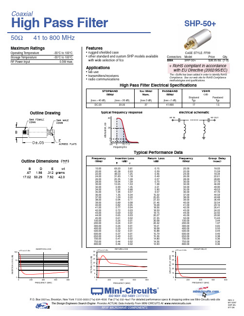
RN-153.3SHP中文资料
- 格式:pdf
- 大小:91.94 KB
- 文档页数:3
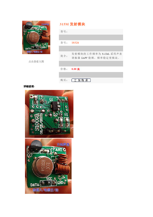
点击查看大图315M发射模块型号:货号:10326简介:发射模块的工作频率为315M,采用声表谐振器SAW稳频,频率稳定度极高。
价格:8.00元购买:详细说明:主要技术指标:1。
通讯方式:调幅AM2。
工作频率:315MHZ (可以提供433MHZ,购货时请特别注明)3。
频率稳定度:±75KHZ4。
发射功率:≤500MW5。
静态电流:≤0.1UA6。
发射电流:3~50MA7。
工作电压:DC 3~12V无线数据传输广泛地运用在车辆监控、遥控、遥测、小型无线网络、无线抄表、门禁系统、小区传呼、工业数据采集系统、无线标签、身份识别、非接触RF智能卡、小型无线数据终端、安全防火系统、无线遥控系统、生物信号采集、水文气象监控、机器人控制、无线232数据通信、无线485/422数据通信、数字音频、数字图像传输等领域中。
DF数据发射模块的工作频率为315M,采用声表谐振器SAW稳频,频率稳定度极高,当环境温度在-25~+85度之间变化时,频飘仅为3ppm/度。
特别适合多发一收无线遥控及数据传输系统。
声表谐振器的频率稳定度仅次于晶体,而一般的LC振荡器频率稳定度及一致性较差,即使采用高品质微调电容,温差变化及振动也很难保证已调好的频点不会发生偏移。
DF发射模块未设编码集成电路,而增加了一只数据调制三极管Q1,这种结构使得它可以方便地和其它固定编码电路、滚动码电路及单片机接口,而不必考虑编码电路的工作电压和输出幅度信号值的大小。
比如用PT2262等编码集成电路配接时,直接将它们的数据输出端第17脚接至DF数据模块的输入端即可。
DF数据模块具有较宽的工作电压范围3~12V,当电压变化时发射频率基本不变,和发射模块配套的接收模块无需任何调整就能稳定地接收。
当发射电压为3V时,空旷地传输距离约20~50米,发射功率较小,当电压5V时约100~200米,当电压9V时约300~500米,当发射电压为12V时,为最佳工作电压,具有较好的发射效果,发射电流约60毫安,空旷地传输距离700~800米,发射功率约500毫瓦。
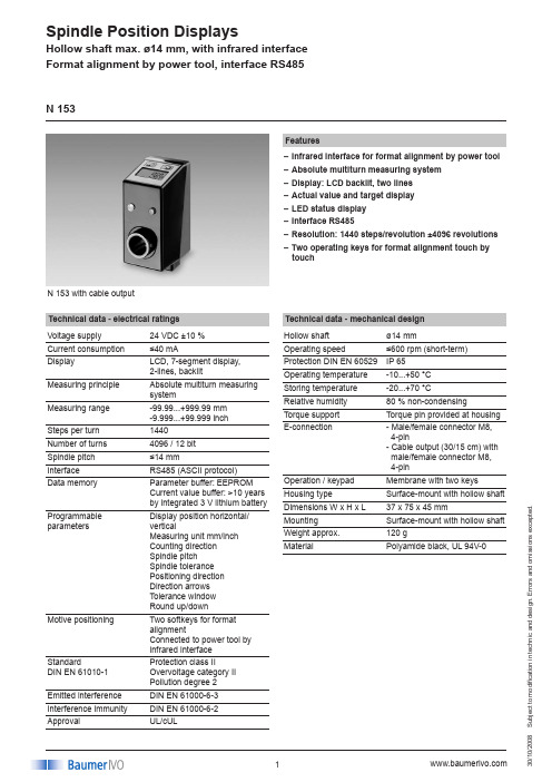
S u b j e c t t o m o d i fi c a t i o n i n t e c h n i c a n d d e s i g n . E r r o r s a n d o m i s s i o n s e x c e p t e d .008N 153 with cable outputFeaturesInfrared interface for format alignment by power tool –Absolute multiturn measuring system –Display: LCD backlit, two lines –Actual value and target display –LED status display –Interface RS485–Resolution: 1440 steps/revolution ±4096 revolutions –Two operating keys for format alignment touch by –touchTechnical data - electrical ratings Voltage supply 24 VDC ±10 %Current consumption ≤40 mADisplayLCD, 7-segment display,2-lines, backlitMeasuring principle Absolute multiturn measuring systemMeasuring range -99.99...+999.99 mm -9.999...+99.999 inch Steps per turn 1440Number of turns 4096 / 12 bit Spindle pitch ≤14 mmInterface RS485 (ASCII protocol)Data memoryParameter buffer: EEPROM Current value buffer: >10 years by integrated 3 V lithium battery Programmable parametersDisplay position horizontal/verticalMeasuring unit mm/inch Counting direction Spindle pitchSpindle tolerance Positioning direction Direction arrows Tolerance window Round up/downMotive positioningTwo softkeys for format alignmentConnected to power tool by infrared interface StandardDIN EN 61010-1Protection class IIOvervoltage category II Pollution degree 2Emitted interference DIN EN 61000-6-3Interference immunity DIN EN 61000-6-2ApprovalUL/cULN 153Technical data - mechanical design Hollow shaft ø14 mmOperating speed ≤600 rpm (short-term)Protection DIN EN 60529IP 65Operating temperature -10...+50 °C Storing temperature -20...+70 °CRelative humidity 80 % non-condensingTorque support Torque pin provided at housing E-connection- Male/female connector M8, 4-pin- Cable output (30/15 cm) with male/female connector M8, 4-pinOperation / keypad Membrane with two keys Housing type Surface-mount with hollow shaft Dimensions W x H x L 37 x 75 x 45 mmMounting Surface-mount with hollow shaft Weight approx.120 gMaterialPolyamide black, UL 94V-0S u b j e c t t o m o d i fi c a t i o n i n t e c h n i c a n d d e s i g n . E r r o r s a n d o m i s s i o n s e x c e p t e d .008N 153Part number N 153.13AA01Hollow shaftA Hollow shaft ø14 mmDisplay A InclinedVoltage supply 324 VDCE-connection0Connector output M8 1Cable output M8Interface1RS485AccessoriesConnectors and cables (page %S)Z 178.A01Adaptor cable between cable connector M8 and female M16, 1 mZ 178.AW1Cable connector M8, 4-pin, less cable with integrated terminating resistor 120 ΩZ 178.B01Mating connector M8, 4-pin, less cable Z 178.D05Data and supply cable M8, Master to N 150 and N 155, 5 mZ 178.S01Cable connector M8, 4-pin, less cable Z 178.V01Coupling cable 1 m between M8 and M8multicon AccuDrive is an economical system for mobile, motive format alignment. By AccuDrive positioning of shafts to the desired format is quick, accurate and less fussy hand crank operations. Saving setup times and avoiding editing errors are consequently the most convincing arguments. The electrically commutated professional power tool ASMIR serves as mobile actuator that communicates with N 153 spindle position displays by infrared interface. Red and green status LEDs provided at the position display indicate the operator which shafts require alignment. A flashing LED indicates the positioning order.The power tool is a vital help in aligning the respective shafts to the new format. Select the desired positioning di -rection by aid of the two pushbuttons provided at the power tool. Press and hold the start button to start the positioning operation at slow speed with increasing acceleration. This way, the operator is able to proceed the positioning opera -tion in direct sight with an accuracy of ±1/100 mm.Any shaft positions once effected can be filed under a parameter profile in the control to be recalled any time. By serial interface maximum 32 spindle position displays may be networked to PC or PLC. Through solutions are real -ized by memory controller N 242 as memory and operating terminal where max. 100 format profiles can be entered and saved by Teach-in.DescriptionS u b j e c t t o m o d i fi c a t i o n i n t e c h n i c a n d d e s i g n . E r r o r s a n d o m i s s i o n s e x c e p t e d .008N 153SPA – connector and female connector, 4-pin Connector Assignment Pin 1 Tx/Rx-, RS485Pin 2 Tx/Rx+, RS485Pin 3 Sensor supply +24 V Pin 4 Sensor supply 0 V24312431M8 connectorM8 female connectorTerminal assignmentDimensionsS u b j e c t t o m o d i fi c a t i o n i n t e c h n i c a n d d e s i g n . E r r o r s a n d o m i s s i o n s e x c e p t e d .008N 153。

1 General DescriptionEasyPoint™ N35P103 is a miniature joystick module concept based on contact-less, magnetic movement detection. The two-dimensional linear encoder IC AS5011 / AS5013 is mounted on the bottom side of the application’s PCB, and monitors the movement of the magnet incorporated into the knob and provides directly the x and y coordinates via I²C output. An integrated mechanical push button built in the module provides a “select” function. Figure 1. N35P103-xxxxx-H2 BenefitsHigh reliability due to magnetic contact-less sensing Easy to use and fast integration3 Key FeaturesSmall form factorLateral magnet movement radius up to +/-0.7mm Direct knob force feedback Push button output SMD mounting4 ApplicationsThe EasyPoint™ N35P103 in combination with the AS5011 / AS5013 is ideal for small form factor navigation user interfaces in battery driven portable devices, such asMobile phones (especially for gaming) Remote Controls Gaming ConsolesAnalog joysticks (360 degree) MP3 players PDA’s, PND, MID GPSFigure 2. Typical ApplicationEasyPoint TM N35P103Single Module (without IC, with push button)N35P103AS5011/AS5013 (IC)EP ™ module footprintMain Board (PCB)5 Mechanical DrawingFigure 3. N35P103 Dimensions (mm ±0.15)Figure 4. Recommended PCB Layout (mm ±0.05) & Circuit DiagramFigure 5. Recommended Stencil Design for 4 GND-PadsFigure 6. Recommended on Casing Design6 Application using AS5011/AS5013 2D Linear EncoderFigure 7. Application DiagramFor further information, please refer to the austriamicrosystems AS5011 encoder application note AN5011-20: /eng/products/magnetic-encoders/EasyPoint-Encoder/EasyPoint-AS5011/EasyPoint-AS5011-Downloads/EasyPoint-AS5011-DownloadsAnd please refer to the austriamicrosystems AS5013 encoder application note AN5013-20:/eng/products/magnetic-encoders/EasyPoint-Encoder/EasyPoint-AS5013/EasyPoint-AS5013-Downloads/EasyPoint-AS5013-DownloadsKnob AS5011/AS5013 2D linear encode Ma gnetDome switch + Mylar tapeMain board (PCB)0.5~1.5mm thickness recommended7 Specifications7.1 Mechanical SpecificationsTable 1. Mechanical SpecificationsParameter NoteNumber of operating shafts Single shaftShaft material PA46Housing material PA46Shell material Stainless Steel or Copper alloyTravel (XY operation) ±0.50mm (±10%)Travel (Z push operation) 0.20mm (±0.05mm) Directional operating force (XY direction) 0.50N (±0.10N)Push operating force (Z direction) 1.80N (±15%)Vibration 10-500-10Hz 15 minutes, 12 cycles, 3 axes (total 36 cycles) Operating life – XY direction Each direction > 1 million cyclesOperating life – Push Z direction > 1 million cyclesShaft strength (XYZ direction) > 3.0 kgfOver force 1.5kgf, > 100k cycles7.2 Electrical SpecificationsTable 2. Electrical SpecificationsParameter Min Max Unit Note Contact resistance 500 mΩNorm: EIA-364-23 Dielectric withstanding voltage 100 Vac Norm: EIA-364-20 Insulation resistance 100 MΩNorm: EIA-364-21, 100VdcBouncing (On/Off) 5 ms Rate: 2 times/sec.7.3 Environmental SpecificationsTable 3. Environmental SpecificationsParameter NoteOperating temperature range -20 ~ +70°CStorage temperature range -40 ~ +85°CHumidity non-condensing 5 ~ 85% RHDegrees of protection IP 5X7.4 Recommended Reflow Temperature ProfileFigure 8. Recommended Reflow Temperature ProfileNote: Do not wash the module! Do not use flux cleaner or solder paste remover!8 Table of Contents1General Description (1)2Benefits (1)3Key Features (1)4Applications (1)5Mechanical Drawing (2)6Application using AS5011/AS5013 2D Linear Encoder (4)7Specifications (5)7.1Mechanical Specifications (5)7.2Electrical Specifications (5)7.3Environmental Specifications (5)7.4Recommended Reflow Temperature Profile (6)8Table of Contents (7)Revision HistoryTable 4. Revision History Revision DateOwnerDescription1.00 25-May-2011 Alfred Binder Initial release1.01 21-Jun-2011 Alfred Binder Minor changes on text and formatCopyrightsCopyright © 1997-2011, austriamicrosystems AG, Tobelbaderstrasse 30, 8141 Unterpremstaetten, Austria-Europe. Trademarks Registered ®. All rights reserved. The material herein may not be reproduced, adapted, merged, translated, stored, or used without the prior written consent of the copyright owner.All products and companies mentioned are trademarks or registered trademarks of their respective companies.DisclaimerDevices sold by austriamicrosystems AG are covered by the warranty and patent indemnification provisions appearing in its Term of Sale. austriamicrosystems AG makes no warranty, express, statutory, implied, or by description regarding the information set forth herein or regarding the freedom of the described devices from patent infringement. austriamicrosystems AG reserves the right to change specifications and prices at any time and without notice. Therefore, prior to designing this product into a system, it is necessary to check with austriamicrosystems AG for current information. This product is intended for use in normal commercial applications. Applications requiring extended temperature range, unusual environmental requirements, or high reliability applications, such as military, medical life-support or life-sustaining equipment are specifically not recommended without additional processing by austriamicrosystems AG for each application. For shipments of less than 100 parts the manufacturing flow might show deviations from the standard production flow, such as test flow or test location.The information furnished here by austriamicrosystems AG is believed to be correct and accurate. However, austriamicrosystems AG shall not be liable to recipient or any third party for any damages, including but not limited to personal injury, property damage, loss of profits, loss of use, interruption of business or indirect, special, incidental or consequential damages, of any kind, in connection with or arising out of the furnishing, performance or use of the technical data herein. No obligation or liability to recipient or any third party shall arise or flow out of austriamicrosystems AG rendering of technical or other services.Contact InformationHeadquartersaustriamicrosystems AGTobelbaderstrasse 30A-8141 Schloss Premstaetten, AustriaTel: +43 (0) 3136 500 0Fax: +43 (0) 3136 525 01For Sales Offices, Distributors and Representatives, please visit:/contact分销商库存信息: AMSN35P103。


UL153轻便灯具标准本标准第一版到第十版的标题为“protable Electric Lamps”第一版:1952年10月第二版:1955年8月第三版:1958年3月第四版:1970年9月第五版:1960年8月第六版:1978年8月第七版:1981年4月第八版:1982年4月第九版:1988年9月第十版:1994年5月第十一版:1995年5月第十二版:2002年3月25日最新的ANSL/UL153依据2002年9月12日公布的美国国家标准,第十二版ANSL/UL153安全标准在连续维护的情况下通过2002年10月10日的修订,每一版本的修订,都是经过美国国家标准化组织在出版物上公布。
如果对本标准有建议和要求,请与UL总部联系。
地址:THE UL-RTP STANDARS DEPARTMENTS 12 LABORATORYDRRESEARCH TRIANGLE PRK NC 27707-3995UL所建立的某些条款是依据所包含的生效日期立即生效的。
本标准的修订部分将另行期出版,并注明发行日期。
如果一个UL标准同时采用了最新的修订版,那么它也是有效的,所有修订内容将在修订版里作详细说明。
目绿序言说明:1、范围2、术语3、组织的应用4、元件5、测量的单位6、修订记绿第一部分结构机械结构概述7、概述8、组装和包装9、外壳10、外壳金属厚度11、防腐蚀保护12、聚合附件13、装饰聚合物14、外壳孔15、走线管道16、灯罩构造17、拉力缓冲装置18、带有玩具功能的灯具19、耐液体损坏20、灯具包含的危险物体电气构造概述21、概述22、组装和包装23、带电部分的可接近性24、电气间隙25、绝缘材料26、电气额定值27、导线28、连接29、连接易活动灯具的电线30、导线保护31、电源线32、附属插头33、内部连接元件34、可替换的电源线连接35、极性和识别36、接地和连接37、电路38、次级电压电路39、次级电路的分离40、元件的安装41、灯头42、开关和调光器43、插座44、变压器45、马达白炽灯具-补充46、概述47、免温度测试灯具47.1 概述47.2 免温度测试的决定47.3 灯罩标准47.4 灯到灯罩的距离47.5 导线绝缘层的距离47.6 其它灯罩设计47A 白炽灯火炬灯具的防护板48、测试48.1 正常温度测试48.2 白炽火炬灯异常工作测试49、标签50、说明书卤素钨灯-补充51、概述52、机械结构52.1 概述52.2 防护板52.3 火炬灯的防护板52.4灯罩52.5紫外线筛检程式52.6可转动或有活动连接的灯杆53、电气构造53.1 开关53.2 内部连接开关53.3 自动温度调整或限制控制53.4 上下扳动式开关54、测试54.1 正常温度测试54.2 卤素钨灯邻近表面和上方异常工作测试54.3 卤素火炬灯异常工作测试54.4 防护板、灯罩或紫外线筛检程式稳定性测试54.5 聚合灯罩测试XX56、说明书荧光灯具-补充57、概述58、电气构造58.1 镇流器58.2 灯头58.3 电线额定温度58.4 电源线58.5 接地59、测试59.1 正常温度测试59.2 非正常工作启动器短路测试60、免温度测试灯具61、标签高密度放电灯-补充62、概述63、机械构造63.1 金属卤化灯罩和紫外线防护器64、电气构造64.1 灯头64.2 镇流器64.3 电容64.4 非集成填油电容器65、测试65.1 正常温度测试65.2 玻璃碰撞测试65.3 玻3玻璃热擊/被包含测试墙表面、厨柜或器具下安装灯具-补充67、概述68、墙壁上安装灯具68.1 概述68.2 机械构造68.3 电气构造68.4 测试68.5说明书69、架子下安装的灯具69.1 概述69.2 安装方式69.3 电气构造69.4 测试69.5 标签70、安装于器具上的灯具70.1 概述70.2 说明书绳和链悬挂系统-补充71、概述72、机械构造72.1 链72.2 支撑五金件72.3 最大重量73、电气构造73.1 内部电线保护73.2 电源线73.3 灯头和开关74、测试74.1 安装方式测试74.2 悬挂玩具测试75、标签76、说明书夹合式灯具-补充77、概述78、机械构造78.1 夹子79、电器构造79.1 电源线79.22灯头和开关80.1 安装方式测试81、概述82、机械构造82.1 安装法兰83、电气构造83.1 电源线83.2 内部连接线83.3 附加插头和插座83.4 灯头83.5 低压轻便厨柜灯84、测试84.1 正常温度测试85、标签86、说明书用于办公装备的灯具-补充87、概述88、机械构造89、电气构造89.1 电源线89.2 插头和插座89.3 内部连接线89.4 过载保护90、标签91、说明书可转换灯具-补充92、概述93、机械构造93.1 枝形可转换吊灯配件93.2 表面安装可转换配件94、电气结构94.1 接地94.2 极性95、标签96、说明书内部转换灯具-补充要求97、概述98、机械构造99、电气构造99.1 电源线99.3 变压器100、标签轨道型灯具-补充101、概述102、机械构造102.1 轨道102.2 电线和未端灯罩的稳固性102.3 安装方式103、电气构造103.1 电源线103.2 极性103.3 插座104、测试104.1 极性测试的机械方法105、标签106、说明书轻便灯具的元件-补充107、概述108、机械构造108.1 概述108.2 灯罩109、电气构造109.1 概述109.2 电源线109.3 零件的安装110、测试110.1 组装和安装测试111、标签112、说明书工作灯-补充113、概述114、机械构造114.1 组装114.2 防护罩114.3 灯杆114.4 底座115、电气构造115.1 电源线115.2 接地型附加插头115.4 上下扳动式开关115.5 集成电路116、测试116.1 正常温度测试116.2 卤钨灯测试117、标签潮湿环境的使用-补充118、概述119、机械结构119.1 外壳119.2 防水119.3 防腐蚀119.4 导线孔119.5 密封垫119.6 安装杆120、电气结构120.1 电源线120.2 接地型附加插头120.3 插座120.4 灯头120.5 开关120.6 绝缘121、测试121.1 潮湿位置测试122、标签123、说明书第二部分性能概述-正常温度测试124、概述125、测试方式-概述125.1 温度限制125.2 测试持续时间125.3 用热电偶测量温度125.4 电阻法温度测试125.5 环境温度测试125.6 测试电压、电流和瓦数125.7 高密度放电灯标定的测试状况125.8 白炽测试灯125.9 钨测试灯125.10 荧光测试灯125.11 高密度放电测试灯125.12 灯罩位置和装饰部分126、特定的测试状况-可移动底座和表面安装灯具126.1 概述126.2 测试结果127、特定的测试状况-轻便厨柜灯127.1 非凹形灯127.2 凹形灯127.3 测试结果128、特定的测试状况-工作灯128.1 概述128.2 测试结果概述-非正常工作测试129、可调整或复合型灯罩非正常工作测试129.1 概述129.2 测试方式概述129.3 可调整或活动灯罩位置的测试方式129.4 复合型灯罩的测试方式129.5 折叠情况下的测试方式129.6 测试结果130、变压器短路的测试130.1 概述130.2 测试方式130.3 测试结果131、元件失效测试131.1 概述131.2 测试方式131.3 测试结果131A、导体短路与非正常工作测试131A.1 概述131A.2 短路测试方法131A.3 非短路测试方法131A.4 测试结果机械测试概述132、稳定性测试132.1 概述132.2 测试方式概述132.3 易活动的或铰接式灯杆的测试方式132.4 元件负载测试方式132.5 测试结果133、张力缓冲测试134、落地测试134.1 概述134.2 测试方式134.3 测试结果135、螺钉的牢固性测试135.1 概述135.2 测试方式135.3 测试结果带电测试概述136、接地连续性测试136.1 概述136.2 测试方式136.3 测试结果137、绝缘耐高压测试137.1 概述137.2 测试方式137.3 测试结果138、变压器输出电压测试138.1 概述138.2 测试方式138.3 测试结果139、低压带铰链或可移动部分的周期性测试139.1 概述139.2 测试方式139.3 测试结果140、抗湿气测试140.1 概述140.2 测试方式140.3 测试结果白炽灯测试141、力矩测试141.1 概述141.2 测试方式141.3 测试结果142、灯罩的易燃性测试142.1 概述142.2 测试方式142.3 测试结果钨灯测试143、钨灯临近表面和上方非正常工作测试143.1 概述143.2 测试方式概述143.3 几种状况下的测试方式143.4 垂直表面测试方式143.5 支援表面测试方式143.6 架空式表面测试方式143.7 过载测试方式143.8 测试结果144、卤素火炬灯防护板、灯罩、紫外线过滤的安全性测试144.1 概述144.2 测试方式144.3 测试结果145、卤素钨灯非正常工作测试145.1 概述145.2 测试方式145.3 测试结果146、卤素火炬灯垂直墙面测试146.1 概述146.2 测试方式146.3 测试结果147、卤素火炬灯稳定测试147.1 概述147.2 测试方式147.3 测试结果148、可转动的或铰链式卤素火炬灯挡点测试148.1 概述148.2 测试方式148.3 测试结果149、备用元件150、聚合灯罩测试150.1 概述150.2 测试方式150.3 测试结果151、内部开关耐久性测试151.1 概述151.2 测试方式151.3 测试结果152、热溶化密度大小测试152.1 概述152.2 测试方式152.3 测试结果荧光灯测试153、非正常工作-启动器短路测试153.1 概述153.2 测试方式153.3 测试结果高密度放电灯的测试154、玻璃碰撞测试154.1 概述154.2 测试方式154.3 测试结果155、玻璃热击/被包含测试155.1 概述155.2 测试方式155.3 测试结果墙表面或架子下表面安装灯的测试156、安装方式测试-表面安装灯具156.1 概述156.2 测试方式156.3 测试结果绳和链悬挂的灯具测试方式157、安装方式测试-绳和链悬挂的灯具157.1 概述157.2 测试方式概述157.3 挪动灯具的测试方式157.4 悬挂灯具的测试方式157.5 测试结果158、悬挂玩具的测试158.1 概述158.2 测试方式158.3 测试结果夹合式灯具的测试159、夹合式灯的安装方式159.1 概述159.2 测试方式159.3 测试结果轨道型灯的测试160、极性的机械测试160.1 概述160.2 测试方式160.3 测试结果161、轨道夹稳固性的测试161.1 概述161.2 测试方式161.3 测试结果轻便灯具的组装测试162、组装和安装测试162.1 概述162.2 测试方式162.3 测试结果工作灯测试163、防护板安全测试163.1 概述163.2 测试方式163.3 测试结果用于潮湿环境的测试164、雨水和喷水测试164.1 概述164.2 测试方式概述164.3 淋雨测试方式164.4 喷水测试方式164.4 测试结果165、聚合物受热条件下的测试165.1 概述165.2 测试方式165.3 测试结果166、垫圈加速老化测试166.1 概述166.2 测试方式A166.3 测试结果A166.4 测试方式B166.5 测试结果B167、垫圈粘接性测试167.1 概述167.2 测试方式A167.3 测试结果A167.4 测试方式B167.5 测试结果B168、涂层粘性测试168.1 概述168.2 测试方式168.3 测试结果第三部分标签169、概述169.1 格式169.2 格式”A”标签纸169.3 卡片型标签169.4 圆片型标签169.5 生产商的识别169.6 电气额定值169.7 安装方向169.8 热表面标识169.9 内部连接元件169.10 带有完整支架安装架或桌子的灯具169.11 与玩具的类同之处169.12 灯具包含的危险物质的标识170、白炽灯具170.1 灯泡的替换170.2 不带灯罩运输的白炽灯具170.3 防尘盖的移除171、卤素钨灯171.1 单封口灯泡的替换171.2 双封口灯泡的替换171.3 火险和伤害警告171.4 五英尺的最低安装171.5 日期标172、荧光灯172.1 灯泡的替换173、高密度灯173.1 灯的替换173.2 双接头金属卤素灯174、绳和链悬挂的灯175、轻便厨柜灯175.1 识别175.2 摇控的变压器175.3 缩短导线175.4 内部连接插座176、用于办公装置的灯177、可转换的灯具178、内部可互换的灯179、轨道型灯180、轻便灯具元件181、工作灯182、潮湿场所使用第四部分说明书183、概述183.1 位置183.2 组装说明书183.3 极性说明书183.4 内部连接灯具183.5 针形插头183.6 缩短的电线183.7 可改变的电源连接183.8 附合外国标准的插头184、185、186、187、188、189、190、2.专用术语:2.1 以下是对本要求中定义的详细说明2.2 ADAPTER(接合器/接头/承接管)-意于配合基座和为可替换的照明设备配备机械连接和电气连接的照明设备元件。

Large Can Aluminum Electrolytic CapacitorsFEATURES• NEW SIZES FOR LOW PROFILE AND HIGH DENSITY DESIGN OPTIONS • EXPANDED CV VALUE RANGE• HIGH RIPPLE CURRENT• LONG LIFE • CAN-TOP SAFETY VENT• DESIGNED AS INPUT FILTER OF SMPS • STANDARD 10mm (.400") SNAP-IN SPACING NRLM SeriesSPECIFICATIONS(* 47,000µF add 0.14, 68,000µF add 0.35.)Notice for MountingThe space from the top of the can shall be more than (3mm) from chassis or other construction materials so that safety vent has room to expand in case of emer g en c y.Sleeve Color: DarkBlueCan Top Safety VentInsulation Sleeve and Minus Polarity Marking(4.0mm Leads Available As Option)D+1Max.L ± 26.3 ± 10.810(-)(+)MAXIMUM EX P AN S IONFOR SAFETY VENT Approx. 3.0mmRecommended PC Board Mounting Holes:10 ± .1∅= 2 ± 0.1D ∅ ± 0.5ChassisPC BoardPRECAUTIONSPlease review the notes on correct use, safety and precautions found on pages T10 & T11of NIC’s Electrolytic Capacitor catalog . Operating Temperature Range-40 ~ +85°C-25 ~ +85°C Rated Voltage Range 16 ~ 250Vdc 350 ~ 450Vdc Rated Capacitance Range 180 ~ 68,000µF56 ~ 680µFCapacitance Tolerance ±20% (M)Max. Leakage Current (µA)After 5 minutes (20°C)3 x C(µF)VMax. Tan δat 120Hz/20°C W.V. (Vdc)162535506380100160~450Tan δ max.0.50*0.40*0.350.300.250.200.200.15Surge VoltageW.V. (Vdc)162535506380100160S.V. (Vdc)2032446379100125200W.V. (Vdc)180200250350400450--S.V. (Vdc)220250300400450500--Ripple CurrentCorrection Factors Frequency (Hz)50601001205001K 10K ~ 50K -Multiplier at 85°C0.750.800.95 1.00 1.05 1.08 1.15-Low TemperatureStability (10 to 250Vdc)Temperature (°C)0-25-40-----Capacitance Change-5%-15%-30%-----Impedance Ratio 1.539-----Load Life Test2,000 hours at +85°CCapacitance ChangeWithin ±20% of initial measured value Tan δLess than 200% of specifi ed maximum valueLeakage Current Less than specifi ed maximum value Shelf Life Test1,000 hours at +85°C (no load)Capacitance Change Within ±20% of initial measured value Tan δLess than 200% of specifi ed maximum valueLeakage Current Less than specifi ed maximum value Surge Voltage Test Per JIS-C-5141 (table #6, #4)Surge voltage applied: 30 seconds"On" and 5.5 minutes no voltage "Off"Capacitance Change Within ±20% of initial measured value Tan δLess than 200% of specifi ed maximum valueLeakage Current Less than specifi ed maximum value Soldering EffectRefer to MIL-STD-202F Method 210A Capacitance Change Within ±10% of initial measured valueTan δLess than specifi ed maximum value Leakage CurrentLess than specifi ed maximum valueRoHS Compliantincludes all homogeneous materials*See Part Number System for DetailsLarge Can Aluminum Electrolytic CapacitorsNRLM SeriesNRLM 222 M 50V 20X25 FRoHS compliant Case Size (mm) Voltage Rating Tolerance Code PART NUMBER SYSTEMLarge Can Aluminum Electrolytic Capacitors NRLM Series STANDARD PRODUCT LIST, CASE SIZE AND SPECIFICATIONS。
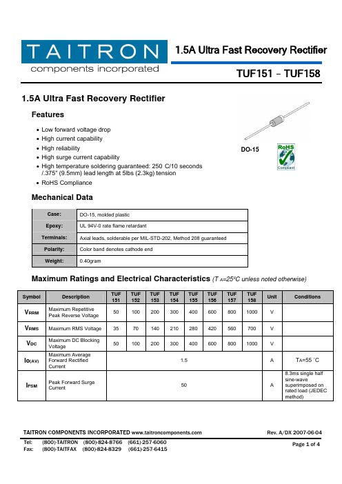
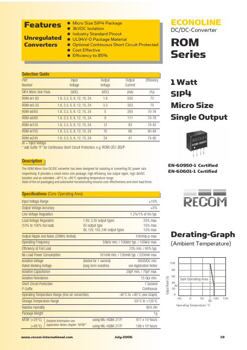
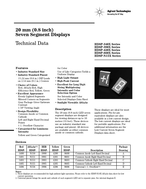
No.2152300-8B(共16页)电路板检查装置RNS系列 LS标准规格书2010年10月欧姆龙株式会社目录1.概要 (3)2.装置的外观 (3)3.装置的构成与动作 (4)3.1 装置的构成 (4)3.2 各单元的机能 (4)4.装置规格 (5)5.机能规格 (6)5.1检查对象电路板 (6)5.2检查项目 (7)5.3 检查程序 (7)5.4 电路板定位 (7)5.5 标准选择规格 (8)5.6 选择配件 (8)5.7 保护机能 (8)6.操作概要 (9)6.1 检查模式 (9)6.2 编程模式 (10)7.I/F (11)7.1 上下游I/F 信号时间图 (11)7.2 上下游连接器规格 (13)7.3 输入输出的内部连接 (14)8.本产品使用时的承诺事项 (15)9.付属品 (16)1.概要本装置是根据预先编制的“检查程序”对通过波峰焊接及回流焊接装置焊接的电路板的焊接状态(S)进行检查的装置。
在检查中使用了通过彩色高光法进行的独有的图像处理技术。
检查结果可以输出到显示器和打印机上。
并且,可将用于区分电路板合格品与不合格品的信号输出给下游装置。
2.装置的外观(单位: mm) *1 作Array*2 安装上下游电路板检知传感器(RNS2出厂标准)时,搬入搬出口处各有22mm的突起,所以横向宽度为964mm。
3.装置的构成与动作3.1 装置的构成本装置如图所示,由各个具有不同机能的单元所构成。
它们在检查中互为关联。
3.2 各单元的机能3.2.1 照相机(镜头)构成本装置的眼睛部分,采用3CCD照相机对电路板进行成像。
分辨率有10、15、20µm/三种像素。
3.2.2 显示器显示器根据主计算机的控制对检查状况及检查结果等用彩色图像进行显示。
3.2.3 主计算机依据操作人员的操作对电路板的种类做出选择并输出检查结果等,对本装置进行全体控制。
(1) HD 中预装有OS 及本装置的软件,元件库和检查程序。


AM-RRS3-XXXAM SUPERHETRODYNE R ECEIVERS .AM-RRQ3-XXXRRQ3• Sensitivity Typ -107dbm • PLL Synthesizer Front End • Sleep Mode• Compact Hybrid Module. • Ceramic Substrate• 315 / 433 / 868MHz Available • Very High Frequency Stability • Receiving Range Up To 100 Metres. • CMOS/TTL Compatible Output. •Single Supply Voltage 5V. • Operates from –25 - +85o C• Compatible With R.F. Solutions AM Transmitters.•Compliant to ETS300-220 RRS3• Sensitivity Typ -106dbm •Saw Filter Front End.The R.F. Solutions AM Superheterodyne Receivers are compact modules, which can be used to capture undecoded data from any equivalent AM Transmitter, such as R.F. Solutions AM-RT4 range of transmitters. (See AM Transmitter datasheet).Receivers are manufactured on a ceramic substrate incorporates either a SAW Filter and pre amplifier front end or PLL Synthesizer for maximum sensitivity and reduced EMC emissions. These modules show a very high frequency stability over a wide operating temperature even when subjected to mechanical vibrations or manual handling offering a very cost effective solution. Block diagramAM SUPERHETRODYNE R ECEIVERS .AM-RRS3-XXXMechanical DimensionsPin DescriptionsRRS3RRQ3Pin No Pin Name Pin No Pin Name 1 +Vcc 1 +Vcc 2 GND2 GND3 DATA IN (Antenna)3 DATA IN (Antenna)7 GND 7 GND 11 GND 11 GND 12 NC 12 NC13 NC 13 RSSI (output) 14 DATA OUT14 DATA OUT15+VCC15PD (Power Down input)0 = Standby Mode (I standby 100nA max) 5V = Normal OperationElectrical Characteristics (Applies to all variants below)Ambient temperature= 25o C.Electrical CharacteristicsMinTypicalMaxDimensionSupply Voltage (Vcc) 4.5 5 5.5 V Supply Current5 6 mA Receiver Frequency 315MHz variants 315 MHz Receiver Frequency 433MHz variants 433.92 MHz Receiver Frequency 868MHz variants 868.35MHz Low Level Output Voltage 0.8 V High Level Output Voltage Vcc-1 V Operating Temperature Range-25+80o CAM-RRS3 Electrical Characteristics Electrical CharacteristicsMinTypicalMaxDimensionR.F Sensitivity (100% AM) -106 dBm 3dB Bandwidth +/-400 KHz Max Data Rate4.8 KHz Turn on Time (Power on to Data valid) 20 mSecs Level of Emitted Spectrum-70-65dBmAM-RRQ3 Electrical Characteristics Electrical CharacteristicsMinTypicalMaxDimensionR.F Sensitivity (100% AM) -107 dBm 3dB Bandwidth +/-200 KHz Max Data Rate4.8 KHz Level of Emitted Spectrum-70dBmNotesPins on 0.1" pitchPin Dims :0.25 x 0.50mmAM SUPERHETRODYNE R ECEIVERS . AM-RRS3-XXXApplication CircuitPart numberingAM-RRS3-315 Receiver Module 315MHz AM-RRS3-418 Receiver Module 418MHz AM-RRS3-433Receiver Module 433MHzAM-RRQ3-315 Receiver Module 315MHz AM-RRQ3-433 Receiver Module 433MHz AM-RRQ3-868Receiver Module 868MHzShould you require further assistance, please call;R. F. Solutions Ltd.,Unit 21, Cliffe Industrial Estate,South Street, Lewes,E Sussex, BN8 6JL. England.Tel +44 (0)1273 898 000. Fax +44 (0)1273 480 661.Email sales@ RF Solutions is a member of the Low Power Radio Association.Serial Data OutputO/P 1O/P 2O/P 3O/P 4Transmitter Low Battery。

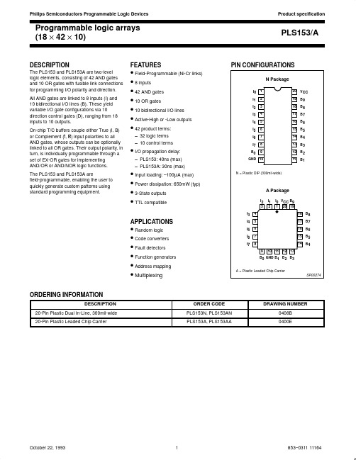
20 mm (0.8 inch)Seven Segment Displays Technical DataRed AlGaAs [1]HER Yellow GreenPackage HDSP-HDSP-HDSP-HDSP-HDSP-DescriptionDrawing3400N150390042008600Common Anode Left Hand Decimal A 3401N151390142018601Common Anode Right Hand Decimal B 3403N153390342038603Common Cathode Right Hand Decimal C 3405N155390542058605Common Cathode Left Hand Decimal D 3406N156390642068606Universal ±1. Overflow [2]ENotes:1. These displays are recommended for high ambient light operation. Please refer to the HDSP-N10X AlGaAs data sheet for low current operation.2. Universal pinout brings the anode and cathode of each segment's LED out to separate pins. See internal diagram E.DevicesFeatures• Industry Standard Size • Industry Standard Pinout 15.24 mm (0.6 in.) DIP Leads on 2.54 mm (0.1 in.) Centers • Choice of ColorsRed, AlGaAs Red, HighEfficiency Red, Yellow, Green • Excellent Appearance Evenly Lighted Segments Mitered Corners on Segments Gray Package Gives Optimum Contrast±50° Viewing Angle • Design FlexibilityCommon Anode or Common CathodeLeft and Right Hand Decimal Points±1. Overflow Character • Categorized for Luminous IntensityYellow and Green Categorizedfor ColorUse of Like Categories Yields a Uniform Display • High Light Output • High Peak Current• Excellent for Long Digit String Multiplexing Intensity and Color Selection OptionSee Intensity and ColorSelected Displays Data Sheet • Sunlight Viewable AlGaAsDescriptionThe 20 mm (0.8 inch) LED seven segment displays are designed for viewing distances up to 10metres (33 feet). These devices use an industry standard size package and pinout. All devices are available as either common anode or common cathode.These displays are ideal for most applications. Pin for pin equivalent displays are alsoavailable in a low current design.The low current displays are ideal for portable applications. For additional information see the Low Current Seven Segment Displays data sheet.HDSP-340X Series HDSP-390X Series HDSP-420X Series HDSP-860X Series HDSP-N15X Series元器件交易网Package DimensionsInternal Circuit DiagramED C B AAbsolute Maximum RatingsRed AlGaAs Red HER Yellow Green HDSP-3400HDSP-N150HDSP-3900HDSP-4200HDSP-8600DescriptionSeriesSeriesSeriesSeriesSeries UnitsAverage Power per Segment 11596105105105mW or DPPeak Forward Current per 200[1]160[3]135[5]135[5]90[7]mA Segment or DPDC Forward Current per 50[2]40[4]40[6]40[6]30[8]mA Segment or DP Operating Temperature -40 to +100-20 to +100[9]-40 to +100-40 to +100°C RangeStorage Temperature Range -55 to +100°C Reverse Voltage per 3.0VSegment or DPLead Solder Temperature for 3 Seconds (1.60 mm 260°C[0.063 in.] below seating plane)Notes:1. See Figure 1 to establish pulsed conditions.2. Derate above 45°C at 0.83 mA/°C.3. See Figure 2 to establish pulsed conditions.4. Derate above 55°C at 0.8 mA/°C.5. See Figure 7 to establish pulsed conditions.Device SeriesParameterSymbol Min.Typ.Max.Units Test Conditions Luminous Intensity/Segment [1,2]I V 5001200µcd I F = 20 mA (Digit Average)Forward Voltage/Segment or DPV F 1.6 2.0V I F = 20 mAHDSP-Peak Wavelength λPEAK 655nm 340XDominant Wavelength [3]λd 640nm Reverse Voltage/Segment or DP [4]V R 3.020V I R = 100 µA Temperature Coefficient of ∆V F /°C -2mV/°C V F /Segment or DPThermal Resistance LED Junction-R θJ-PIN375°C/Wto-PinElectrical/Optical Characteristics at T A = 25°CRed6. Derate above 50°C at 0.73 mA/°C.7. See Figure 8 to establish pulsed conditions.8. Derate above 50°C at 0.54 mA/°C.9. For operation below -20°C, contact your local Agilent components sales office or an authorized distributor.AlGaAs RedDeviceSeries Parameter Symbol Min.Typ.Max.Units Test Conditions Luminous Intensity/Segment[1,2,5]I V 6.014.0mcd I F = 20 mA(Digit Average)1.8V I F = 20 mAForward Voltage/Segment or DP V F2.03.0V I F = 100 mAHDSP-N15X Peak WavelengthλPEAK645nmDominant Wavelength[3]λd637nmReverse Voltage/Segment or DP[4]V R 3.015V I R = 100 µATemperature Coefficient of∆V F/°C-2mV/°CV F/Segment or DPThermal Resistance LED Junction-RθJ-PIN430°C/W/to-Pin SegHigh Efficiency RedDeviceSeries Parameter Symbol Min.Typ.Max.Units Test Conditions33507000µcd I F = 100 mA Peak: Luminous Intensity/Segment[1,2]I V 1 of 5 df(Digit Average)4800µcd I F = 20 mA Forward Voltage/Segment or DP V F 2.6 3.5V I F = 100 mA HDSP-390X Peak WavelengthλPEAK635nmDominant Wavelength[3]λd626nmReverse Voltage/Segment or DP[4]V R 3.025V I R = 100 µATemperature Coefficient of∆V F/°C-2mV/°CV F/Segment or DPThermal Resistance LED Junction-RθJ-PIN375°C/W/to-Pin SegYellowDeviceSeries Parameter Symbol Min.Typ.Max.Units Test Conditions22007000µcd I F = 100 mA Peak: Luminous Intensity/Segment[1,2]I V 1 of 5 df(Digit Average)3400µcd I F = 20 mA Forward Voltage/Segment or DP V F 2.6 3.5V I F = 100 mA HDSP-420X Peak WavelengthλPEAK583nmDominant Wavelength[3,6]λd581.5586592.5nmReverse Voltage/Segment or DP[4]V R 3.025.0V I R = 100 µATemperature Coefficient of∆V F/°C-2mV/°CV F/Segment or DPThermal Resistance LED Junction-RθJ-PIN375°C/W/to-Pin SegGreenDeviceSeries Parameter Symbol Min.Typ.Max.Units Test Conditions6801500µcd I F = 10 mA Luminous Intensity/Segment[1,2]I V(Digit Average)`1960µcd I F = 50 mA Peak:1 of 5 dfForward Voltage/Segment or DP V F 2.1 2.5V I F = 10 mA HDSP-Peak WavelengthλPEAK566nm860XDominant Wavelength[3,6]λd571577nmReverse Voltage/Segment or DP[4]V R 3.050.0V I R = 100 µATemperature Coefficient of∆V F/°C-2mV/°CV F/Segment or DPThermal Resistance LED Junction-RθJ-PIN375°C/W/to-Pin SegNotes:1. Case temperature of the device immediately prior to the intensity measurement is 25°C.2. The digits are categorized for luminous intensity. The intensity category is designated by a letter on the side of the package.3. The dominant wavelength, λd, is derived from the CIE chromaticity diagram and is that single wavelength which defines the color ofthe device.4. Typical specification for reference only. Do not exceed absolute maximum ratings.5. For low current operation, the AlGaAs Red HDSP-N100 series displays are recommended. They are tested at 1 mA dc/segment andare pin for pin compatible with the HDSP-N150 series.6. The Yellow (HDSP-4200) and Green (HDSP-8600) displays are categorized for dominant wavelength. The category is designated bya number adjacent to the luminous intensity category letter.Figure 3. Maximum Allowable DC Current vs.Ambient Temperature.Figure 6. Relative Efficiency (Luminous Intensity per Unit Current) vs. Peak Current.I – FORWARD CURRENT PER SEGMENT – mA FR E L AT I V E L U M I N O U S I N T E N S I T Y (N O R M A L I Z E D T O 1 A T 20 m A )I – PEAK FORWARD CURRENT PER SEGMENTPEAK– R E L A T I V E E F F I C I E N C Y O R M A L I Z E D T O 1 A T 20 m A )E A K Figure 5. Relative Luminous Intensity vs. DC Forward Current.Figure 4. Forward Current vs. Forward Voltage.4504050T – AMBIENT TEMPERATURE – °C 3530252015105AI M A X – M A X I M U M D C C U R R E N T P E R S E G M E N T – m AD C180160200V – FORWARD CURRENT – V 140120100FI – F O R W A R D C U R R E N T P E RS E G M E N T – m AF Figure 1. Maximum Allowable Peak Current vs. Pulse Duration – Red.Figure 2. Maximum Allowed Peak Current vs. PulseDuration – AlGaAs Red.10t – PULSE DURATION – µs Pt – PULSE DURATION – µs PRed, AlGaAs RedFigure 11. Relative Luminous Intensity vs. DCForward Current.Figure 9. Maximum Allowable DC Current vs.Ambient Temperature.I – FORWARD CURRENT PER SEGMENT – mA FR E L A T I V E L U M I N O U S I N T E N S I T Y (N O R M A L I Z E D T O 1 A T 20 m A F O R H E R A N D Y E L L O W ;A T 10 m A F O R G R E E N )4504050T – AMBIENT TEMPERATURE – °C 3530252015105A I M A X – M A X I M U M D C C U R R E N T P E RS E G M E N T – m AD C Figure 7. Maximum Allowed Peak Current vs. PulseDuration – HER, Yellow.10t – PULSE DURATION – µS Pt – PULSE DURATION – µS PHER, Yellow, GreenFigure 8. Maximum Allowed Peak Current vs. Pulse Duration – Green.Figure 10. Forward Current vs. Forward Voltage.14012080604020V – FORWARD VOLTAGE – VF100I – F O R W A R D C U R R E N T P E R S E G M E N T – m AF – R E L A T I V E E F F I C I E N C Y (E D T O 1 A T 100 m A F O R H E R A N D Y E L L O W ; A T 10 m A F O RG R E E N )I – PEAK FORWARD CURRENT PER SEGMENT – mAPEAKFigure 12. Relative Efficiency (Luminous Intensity per Unit Current) vs. Peak Current.元器件交易网Contrast EnhancementFor information on contrastenhancement please seeApplication Note 1015.Soldering/CleaningCleaning agents from the ketonefamily (acetone, methyl ethylketone, etc.) and from thechlorinated hydrocarbon family(methylene chloride, trichloro-ethylene, carbon tetrachloride,etc.) are not recommended forcleaning LED parts. All of thesevarious solvents attack ordissolve the encapsulatingepoxies used to form the packageof plastic LED parts.For information on solderingLEDs please refer to ApplicationNote 1027.Data subject to change.Copyright © 1999 Agilent Technologies, Inc.Obsoletes 5963-7390E (4/95)5964-6426E (11/99)。

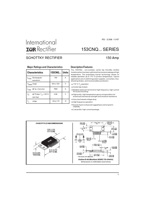
SCHOTTKY RECTIFIER153CNQ... SERIES150 AmpPD - 2.538 11/971CASE STYLE AND DIMENSIONSOutline D-60 (Modified JEDEC TO-249AA)Dimensions in millimeters and inchesMajor Ratings and Characteristics I F(AV)Rectangular150A waveform V RRM range80 to 100V I FSM @ tp = 5 µs sine 7000A V F @ 75 Apk, T J = 125°C 0.80V(per leg)T Jrange- 55 t o 175°CCharacteristics153CNQ...UnitsThe 153CNQ... non-isolated, center tap Schottky rectifiermodule series has been optimized low reverse leakage at high temperature. The proprietary barrier technology allows for reliable operation up to 175° C junction temperature. Typical applications are in switching power supplies, converters, free-wheeling diodes, and reverse battery protection.175° C T J operation Center tap moduleMultiple leads per terminal for high frequency, high current PC board mountingHigh purity, high temperature epoxy encapsulation for enhanced mechanical strength and moisture resistance Very low forward voltage drop High frequency operationGuard ring for enhanced ruggedness and long term reliabilityLow profile, high current packageDescription/Features* PRE-SOLDER CHIP DIMENSIONS153CNQ... Series2PD - 2.538 11/97T J Max. Junction Temperature Range -55 to 175°C T stgMax. Storage Temperature Range-55 to 175°CR thJC Max. Thermal Resistance Junction0.70°C/W DC operation * See Fig. 4to C ase (Per L eg)R thJC Max. T hermal R esistance J unction0.35°C/W DC o perationto C ase (Per P ackage)R thCS Typical T hermal R esistance, C ase0.10°C/W Mounting s urface ,s mooth a nd g reased to H eatsink wt Approximate W eight 56 (2.0)g (oz.)TMounting T orque Min.40 (35)Max.58 (50)Case StyleD-60 (TO-249AA)Modified JEDECThermal-Mechanical SpecificationsKg-cm (Ibf-in)V FMMax. Forward Voltage Drop 0.96V @ 75A (Per Leg) * See Fig. 1(1)1.19V @ 150A 0.80V @ 75A 0.99V @ 150AI RM Max. Reverse Leakage Current 1.5mA T J = 25 °C (Per Leg) * See Fig. 2(1)20mA T J = 125 °CC T Max. Junction Capacitance (Per Leg)1400pF V R = 5V DC , (test signal range 100Khz to 1Mhz) 25°C L STypical Series Inductance (Per Leg)9.2nH Measured lead to lead 5mm from package bodydv/dt Max. Voltage Rate of Change10,000V/ µs(Rated V R )T J = 25 °C T J = 125 °C Electrical Specifications(1) Pulse Width < 300µs, Duty Cycle <2%V R = rated V RAbsolute Maximum RatingsFollowing any rated load condition and withrated V RRM applied Parameters153CNQ UnitsConditionsI F(AV)Max. Average Forward Current150A50% duty cycle @ T C = 114 °C, rectangular wave form* See Fig. 5I FSM Max. Peak One Cycle Non-Repetitive 70005µs Sine or 3µs Rect. pulse Surge Current (Per Leg) * See Fig. 772010ms Sine or 6ms Rect. pulse E AS Non-Repetitive Avalanche Energy 15mJ T J = 25 °C, I AS = 1 Amps, L = 30 mH(Per L eg)I ARRepetitive Avalanche Current 1ACurrent decaying linearly to zero in 1 µsec(Per L eg)Frequency limited by T J max. V A = 1.5 x V R typicalA Parameters153CNQ UnitsConditionsParameters153CNQ UnitsConditionsPart number153CNQ080153CNQ100V RMax. DC Reverse Voltage (V)V RWM Max. Working Peak Reverse Voltage (V)Voltage Ratings80100153CNQ... Series3PD - 2.538 11/97153CNQ... Series4PD - 2.538 11/97Fig. 7-M ax. N on-Repetitive S urge C urrent (Per L eg)Fig. 5-M ax. A llowable C ase T emperatureVs. A verage F orward C urrent (Per L eg)Fig. 8 - Unclamped Inductive Test CircuitFig. 6 - F orward P ower L oss C haracteristics(Per L eg)FREE-WHEEL DIODE 40HFL40S02CURRENT MONITORHIGH-SPEEDSWITCH IRFP460LDUT Rg = 25 ohmVd = 25 Volt+10010001000010100100010000F S MpN o n -R e p e t i t i v e S u r g e C u r r e n t - I (A )Square Wave Pulse Duration - t (microsec)20406080100120F(AV)Average Forward Current - I (A)0255075100125A l l o w a b l e C a s e T e m p e r a t u r e - (°C )F(AV)Average Forward Current - I (A)。
